EP3228829A1 - Apparatus and method for forming apparatus - Google Patents
Apparatus and method for forming apparatus Download PDFInfo
- Publication number
- EP3228829A1 EP3228829A1 EP17162635.1A EP17162635A EP3228829A1 EP 3228829 A1 EP3228829 A1 EP 3228829A1 EP 17162635 A EP17162635 A EP 17162635A EP 3228829 A1 EP3228829 A1 EP 3228829A1
- Authority
- EP
- European Patent Office
- Prior art keywords
- interface
- article
- fibers
- matrix composite
- ceramic matrix
- Prior art date
- Legal status (The legal status is an assumption and is not a legal conclusion. Google has not performed a legal analysis and makes no representation as to the accuracy of the status listed.)
- Granted
Links
Images


Classifications
-
- F—MECHANICAL ENGINEERING; LIGHTING; HEATING; WEAPONS; BLASTING
- F01—MACHINES OR ENGINES IN GENERAL; ENGINE PLANTS IN GENERAL; STEAM ENGINES
- F01D—NON-POSITIVE DISPLACEMENT MACHINES OR ENGINES, e.g. STEAM TURBINES
- F01D9/00—Stators
- F01D9/02—Nozzles; Nozzle boxes; Stator blades; Guide conduits, e.g. individual nozzles
-
- F—MECHANICAL ENGINEERING; LIGHTING; HEATING; WEAPONS; BLASTING
- F01—MACHINES OR ENGINES IN GENERAL; ENGINE PLANTS IN GENERAL; STEAM ENGINES
- F01D—NON-POSITIVE DISPLACEMENT MACHINES OR ENGINES, e.g. STEAM TURBINES
- F01D11/00—Preventing or minimising internal leakage of working-fluid, e.g. between stages
- F01D11/005—Sealing means between non relatively rotating elements
-
- F—MECHANICAL ENGINEERING; LIGHTING; HEATING; WEAPONS; BLASTING
- F01—MACHINES OR ENGINES IN GENERAL; ENGINE PLANTS IN GENERAL; STEAM ENGINES
- F01D—NON-POSITIVE DISPLACEMENT MACHINES OR ENGINES, e.g. STEAM TURBINES
- F01D11/00—Preventing or minimising internal leakage of working-fluid, e.g. between stages
- F01D11/08—Preventing or minimising internal leakage of working-fluid, e.g. between stages for sealing space between rotor blade tips and stator
- F01D11/10—Preventing or minimising internal leakage of working-fluid, e.g. between stages for sealing space between rotor blade tips and stator using sealing fluid, e.g. steam
-
- F—MECHANICAL ENGINEERING; LIGHTING; HEATING; WEAPONS; BLASTING
- F01—MACHINES OR ENGINES IN GENERAL; ENGINE PLANTS IN GENERAL; STEAM ENGINES
- F01D—NON-POSITIVE DISPLACEMENT MACHINES OR ENGINES, e.g. STEAM TURBINES
- F01D25/00—Component parts, details, or accessories, not provided for in, or of interest apart from, other groups
- F01D25/24—Casings; Casing parts, e.g. diaphragms, casing fastenings
- F01D25/246—Fastening of diaphragms or stator-rings
-
- F—MECHANICAL ENGINEERING; LIGHTING; HEATING; WEAPONS; BLASTING
- F05—INDEXING SCHEMES RELATING TO ENGINES OR PUMPS IN VARIOUS SUBCLASSES OF CLASSES F01-F04
- F05D—INDEXING SCHEME FOR ASPECTS RELATING TO NON-POSITIVE-DISPLACEMENT MACHINES OR ENGINES, GAS-TURBINES OR JET-PROPULSION PLANTS
- F05D2230/00—Manufacture
- F05D2230/60—Assembly methods
-
- F—MECHANICAL ENGINEERING; LIGHTING; HEATING; WEAPONS; BLASTING
- F05—INDEXING SCHEMES RELATING TO ENGINES OR PUMPS IN VARIOUS SUBCLASSES OF CLASSES F01-F04
- F05D—INDEXING SCHEME FOR ASPECTS RELATING TO NON-POSITIVE-DISPLACEMENT MACHINES OR ENGINES, GAS-TURBINES OR JET-PROPULSION PLANTS
- F05D2240/00—Components
- F05D2240/10—Stators
- F05D2240/11—Shroud seal segments
-
- F—MECHANICAL ENGINEERING; LIGHTING; HEATING; WEAPONS; BLASTING
- F05—INDEXING SCHEMES RELATING TO ENGINES OR PUMPS IN VARIOUS SUBCLASSES OF CLASSES F01-F04
- F05D—INDEXING SCHEME FOR ASPECTS RELATING TO NON-POSITIVE-DISPLACEMENT MACHINES OR ENGINES, GAS-TURBINES OR JET-PROPULSION PLANTS
- F05D2240/00—Components
- F05D2240/10—Stators
- F05D2240/12—Fluid guiding means, e.g. vanes
- F05D2240/128—Nozzles
-
- F—MECHANICAL ENGINEERING; LIGHTING; HEATING; WEAPONS; BLASTING
- F05—INDEXING SCHEMES RELATING TO ENGINES OR PUMPS IN VARIOUS SUBCLASSES OF CLASSES F01-F04
- F05D—INDEXING SCHEME FOR ASPECTS RELATING TO NON-POSITIVE-DISPLACEMENT MACHINES OR ENGINES, GAS-TURBINES OR JET-PROPULSION PLANTS
- F05D2240/00—Components
- F05D2240/20—Rotors
- F05D2240/30—Characteristics of rotor blades, i.e. of any element transforming dynamic fluid energy to or from rotational energy and being attached to a rotor
-
- F—MECHANICAL ENGINEERING; LIGHTING; HEATING; WEAPONS; BLASTING
- F05—INDEXING SCHEMES RELATING TO ENGINES OR PUMPS IN VARIOUS SUBCLASSES OF CLASSES F01-F04
- F05D—INDEXING SCHEME FOR ASPECTS RELATING TO NON-POSITIVE-DISPLACEMENT MACHINES OR ENGINES, GAS-TURBINES OR JET-PROPULSION PLANTS
- F05D2240/00—Components
- F05D2240/55—Seals
-
- F—MECHANICAL ENGINEERING; LIGHTING; HEATING; WEAPONS; BLASTING
- F05—INDEXING SCHEMES RELATING TO ENGINES OR PUMPS IN VARIOUS SUBCLASSES OF CLASSES F01-F04
- F05D—INDEXING SCHEME FOR ASPECTS RELATING TO NON-POSITIVE-DISPLACEMENT MACHINES OR ENGINES, GAS-TURBINES OR JET-PROPULSION PLANTS
- F05D2300/00—Materials; Properties thereof
- F05D2300/60—Properties or characteristics given to material by treatment or manufacturing
- F05D2300/603—Composites; e.g. fibre-reinforced
- F05D2300/6033—Ceramic matrix composites [CMC]
-
- F—MECHANICAL ENGINEERING; LIGHTING; HEATING; WEAPONS; BLASTING
- F05—INDEXING SCHEMES RELATING TO ENGINES OR PUMPS IN VARIOUS SUBCLASSES OF CLASSES F01-F04
- F05D—INDEXING SCHEME FOR ASPECTS RELATING TO NON-POSITIVE-DISPLACEMENT MACHINES OR ENGINES, GAS-TURBINES OR JET-PROPULSION PLANTS
- F05D2300/00—Materials; Properties thereof
- F05D2300/60—Properties or characteristics given to material by treatment or manufacturing
- F05D2300/614—Fibres or filaments
Definitions
- the present invention is directed to apparatuses and methods for forming apparatuses. More particularly, the present invention is directed to apparatuses including cooperating articles which inhibit leakage from a gas path and methods for forming apparatuses including cooperating articles which inhibit leakage from a gas path.
- certain components such as the shroud surrounding the rotating components in the gas path of the turbine (sometimes referred to as a hot gas path due to the elevated temperatures of the gas traveling through the path), are subjected to extreme temperatures, chemical environments and physical conditions.
- the hot gas traveling through the gas path may degrade materials which are otherwise desirable due to qualities such as their low cost and high reparability.
- shrouds are often constructed in two primary components, an inner shroud which is adjacent to the gas path and which is made from materials which are resistant to the effects of the hot gas, and an outer shroud which is largely isolated from the hot gas, and which may therefore be constructed of less durable materials which have other desirable qualities.
- inner shrouds are typically arranged with a series of shroud segments which abut one another. Each interface provides an opportunity for hot gas to leak through the barrier provided by the inner shroud and contact the outer shroud, potentially degrading the outer shroud.
- a seal such as a laminate seal
- Such seals may be unsuitable, however, for regions of the shroud where the inner shroud is too thin for a laminate seal to be inserted, or too curved for a laminate seal to be inserted, or both.
- an apparatus in an exemplary embodiment, includes a first article, a second article and a third article.
- the first article includes at least one first ceramic matrix composite ply, and is adjacent to a gas path.
- the second article includes at least one second ceramic matrix composite ply, and is adjacent to the gas path and the first article.
- the third article is adjacent to the first article and the second article, with the first article and the second article being disposed between the third article and the gas path.
- the at least one first ceramic matrix composite ply and the at least one second ceramic matrix composite ply define an interface including a first cooperating feature of the at least one first ceramic matrix composite ply and a second cooperating feature of the at least one second ceramic matrix composite ply.
- the first cooperating feature and the second cooperating feature define a restricted flow path from the gas path to the third article.
- the restricted flow path includes a reduced volumetric flow rate of a gas from the gas path to the third article relative to a non-restricted flow path of a non-cooperating interface.
- a method for forming an apparatus includes forming a first cooperating feature into at least one first ceramic matrix composite ply of a first article, forming a second cooperating feature into at least one second ceramic matrix composite ply of a second article, and positioning the first article adjacent to the second article, and the first article and the second article adjacent to a third article.
- the first article, second article, and third article are arranged and configured such that the first article and the second article are disposed between the third article and a gas path.
- the first cooperating feature is aligned with the second cooperating feature to define an interface having a restricted flow path from the gas path to the third article.
- the restricted flow path includes a reduced volumetric flow rate of a gas from the gas path to the third article relative to a non-restricted flow path of a non-cooperating interface.
- an article such as, but not limited to, a turbine component.
- Embodiments of the present disclosure for example, in comparison to concepts failing to include one or more of the features disclosed herein, increase efficiency, increase durability, increase temperature tolerance, reduce overall cost reduce material cost, reduce the need for pressurizing a shroud or similar turbine component, increase required service intervals, produce other advantages, or a combination thereof.
- an apparatus 10 includes a first article 102, a second article 104, and a third article 106.
- the first article 102 includes at least one first ceramic matrix composite ply 108, and is adjacent to a gas path 112 (not shown).
- the second article 104 includes at least one second ceramic matrix composite ply 110, and is adjacent to the gas path 112 and the first article 102.
- the third article 106 is adjacent to the first article 102 and the second article 104, with the first article 102 and the second article 104 being disposed between the third article 106 and the gas path 112.
- the at least one first ceramic matrix composite ply 108 and the at least one second ceramic matrix composite ply 110 define an interface 114.
- the apparatus 10 may be any suitable apparatus, including, but not limited to, a turbine component 100.
- the interface 114 includes a first cooperating feature 116 of the at least one first ceramic matrix composite ply 108 and a second cooperating feature 118 of the at least one second ceramic matrix composite ply 110.
- the first cooperating feature 116 and the second cooperating feature 118 define a restricted flow path from the gas path 112 to the third article.
- the restricted flow path 300 includes a reduced volumetric flow rate of a gas from the gas path 112 to the third article 106 relative to a non-restricted flow path 600 of a non-cooperating interface 602.
- the at least one first ceramic matrix composite ply 108 consists of a single ply. In another embodiment, the at least one first ceramic matrix composite ply 108 includes a plurality of plies. In one embodiment, the at least one second ceramic matrix composite ply 110 consists of a single ply. In yet another embodiment, the at least one second ceramic matrix composite ply 110 includes a plurality of plies.
- the article 10 may be any suitable turbine component 100, including, but not limited to, a shroud (shown), a turbine blade (bucket) shroud, a near flowpath seal, or a nozzle (vane) endwall.
- a shroud shown
- a turbine blade bucket
- a near flowpath seal or a nozzle (vane) endwall.
- the first article 102 is a first inner shroud segment
- the second article 104 is a second inner shroud segment
- the third article 106 is an outer shroud.
- the interface 114 is a hook segment 128 of the shroud 120.
- the at least one first ceramic matrix composite ply 108 and the at least one second ceramic matrix composite ply 110 may independently include any suitable ceramic matrix composite composition, including, but not limited to, a ceramic matrix composite including reinforcing fibers wherein the reinforcing fibers may include, but are not limited to, silicon fibers, carbon fibers, silicon carbide fibers, SCS-6 silicon carbine monofilament fibers, rare-earth silicate fibers, silicon nitride fibers, aluminum oxide fibers, silica fibers, boron fibers, boron carbide fibers, aramid fibers, para-aramid fibers, KEVLARTM para-aramid fibers, refractory metal fibers, superalloy fibers, silica-alumina-magnesia fibers, S-glass fibers, zirconium fibers, beryllium fibers, or a combination thereof, an aluminum oxide-fiber-reinforced aluminum oxide (Ox/Ox), a carbon-fiber-reinforced carbon (C
- the third article 106 may include any suitable composition such as, but not limited to, a metallic composition.
- Suitable metallic compositions include, but are not limited to, a titanium alloy, an aluminum alloy, an aluminum-titanium-based alloy, a steel, a stainless steel, a nickel-based superalloy, an alloy suitable for turbine applications, or a combination thereof.
- the interface 114 may be any suitable interface which establishes restricted flow path 300.
- Suitable interfaces 114 may include, but are not limited to, a bridle interface, a finger interface, a dovetail interface, a dado interface, a groove interface, a tongue and groove interface, a triangular tongue and groove interface, a mortise and tenon interface, a hammer-headed tenon interface, a scarf interface 302 (shown in FIG. 3 ), a plane scarf interface, a nibbed scarf interface, a splice interface, a half lap splice interface 400 (shown in FIG.
- a bevel lap splice interface a tabled splice interface, a tapered finger splice interface, a sawtooth interface, a chevron interface 500 (shown in FIG. 5 ), a sinusoidal interface, or a combination thereof.
- the interface 114 includes a thickness 304.
- the thickness 304 of the interface 114 may be any suitable thickness 304, including, but not limited to, a thickness 304 of at least about 0.045 inches, alternatively at least about 0.06 inches, alternatively at least about 0.075 inches, alternatively less than about 0.4 inches, alternatively less than about 0.35 inches, alternatively less than about 0.3 inches, alternatively less than about 0.25 inches, alternatively less than about 0.2 inches, alternatively less than about 0.15 inches, alternatively less than about 0.1 inches, alternatively between about 0.045 inches to about 0.4 inches, alternatively between about 0.045 inches to about 0.3 inches, alternatively between about 0.045 inches to about 0.2 inches, alternatively between about 0.045 inches to about 0.1 inches.
- the interface 114 includes a curved portion 200 having a curvature of at least about 45°, alternatively at least about 60°, alternatively at least about 75°, alternatively at least about 90°, alternatively at least about 105°, alternatively at least about 120°, alternatively at least about 180°, alternatively at least about 195°.
- the curved portion 200 includes a radius of curvature 202.
- the radius of curvature 202 may be any suitable radius, measured at a mean thickness along the curved portion 200, including, but not limited to, a radius of less than about 0.5 inches, alternatively less than about 0.4 inches, alternatively less than about 0.3 inches, alternatively less than about 0.25 inches, alternatively less than about 0.2 inches, alternatively less than about 0.15 inches, alternatively less than about 0.1 inches.
- incorporation of the first cooperating feature 116 and the second cooperative feature 118 to form the interface 114 is operative to restrict flow from the gas path 112 to the third article 106 wherein the interface 114 includes a curved portion 200 having at least one of a curvature which is too severe and radius of curvature 202 which is too small, in combination with a thickness 304 (as shown in FIG. 3 ) which is too narrow, for a laminate seal to be inserted into the interface 114 and be effective in restricting flow from the gas path 112 to the third article 106.
- a method for forming the article 10 includes forming the first cooperating feature 116 into the at least one first ceramic matrix composite ply 108 of the first article 102, and forming the second cooperating feature 118 into the at least one second ceramic matrix composite ply 110 of the second article 104.
- the first article 102 is positioned adjacent to the second article 104, and the first article 102 and the second article 104 are positioned adjacent to the third article 106.
- the first article 102, second article 104, and third article 106 are arranged and configured such that the first article 102 and the second article 104 are disposed between the third article 106 and a gas path 112.
- the first cooperating feature 116 is aligned with the second cooperating feature 118 to define the interface 114 having the restricted flow path 300 from the gas path 112 to the third article 106.
- Forming the first cooperating feature 116 and the second cooperating feature 118 may include any suitable technique.
- the first cooperating feature 116 is formed in the at least one first ceramic matrix composite ply 108 and the second cooperating feature 118 is formed in the at least one second ceramic matrix composite ply 110, wherein the at least one first ceramic matrix composite ply 108 and the at least one second ceramic matrix composite ply 110 are separate and distinct from one another when the first cooperating feature 116 and the second cooperating features 118 are formed.
- At least one ceramic matrix composite ply is separated into the at least one first ceramic matrix composite ply 108 and the at least one second ceramic matrix composite ply 110, wherein separating the at least one first ceramic matrix composite ply 108 from the at least one second ceramic matrix composite ply 110 forms the first cooperating feature 116 and the second cooperating feature 118.
- Separating the at least one first ceramic matrix composite ply 108 from the at least one second ceramic matrix composite ply 110 may include any suitable severing technique, including, but not limited to cutting, milling, drilling, grinding, abrasive flow machining, abrasive jet machining, laser cutting, plasma cutting, water jet cutting, or a combination thereof
- forming the first cooperating feature 116 and the second cooperating feature 118 includes at least one of machining the first cooperating feature 116 into the at least one first ceramic matrix composite ply 108 and machining the second cooperating feature 118 into the at least one second ceramic matrix composite ply 110.
- forming the first cooperating feature 116 and the second cooperating feature 118 includes machining the first cooperating feature 116 into the at least one first ceramic matrix composite ply 108 and machining the second cooperating feature 118 into the at least one second ceramic matrix composite ply 110. Machining may include any suitable technique, including, but not limited to, a severing technique, diamond grinding, electrical discharge machining, or a combination thereof.
- forming the first cooperating feature 116 and the second cooperating feature 118 includes at least one of molding the at least one first ceramic matrix composite ply 108 to net shape including the first cooperating feature 116 and molding the at least one second ceramic matrix composite ply 110 to net shape including the second cooperating feature 118.
- forming the first cooperating feature 116 and the second cooperating feature 118 includes molding the at least one first ceramic matrix composite ply 108 to net shape including the first cooperating feature 116 and molding the at least one second ceramic matrix composite ply 110 to net shape including the second cooperating feature 118.
- forming the first cooperating feature 116 and the second cooperating feature 118 includes at least one of printing the at least one first ceramic matrix composite ply 108 having the first cooperating feature 116 by a near net shape printing process and printing the at least one second ceramic matrix composite ply 110 having the second cooperating feature 118 by a near net shape printing process.
- forming the first cooperating feature 116 and the second cooperating feature 118 includes printing the at least one first ceramic matrix composite ply 108 having the first cooperating feature 116 by a near net shape printing process and printing the at least one second ceramic matrix composite ply 110 having the second cooperating feature 118 by a near net shape printing process.
- Printing may include any suitable ceramic matrix composite printing process, including, but not limited to extruding a coated pre-impregnated tow by a continuous filament fabrication process.
- printing includes placing and orienting reinforcing fibers and from a fiber feeding print head.
- the fiber feeding print head is mounted on a gantry.
Landscapes
- Engineering & Computer Science (AREA)
- Mechanical Engineering (AREA)
- General Engineering & Computer Science (AREA)
- Turbine Rotor Nozzle Sealing (AREA)
Abstract
Description
- The present invention is directed to apparatuses and methods for forming apparatuses. More particularly, the present invention is directed to apparatuses including cooperating articles which inhibit leakage from a gas path and methods for forming apparatuses including cooperating articles which inhibit leakage from a gas path.
- In gas turbines, certain components, such as the shroud surrounding the rotating components in the gas path of the turbine (sometimes referred to as a hot gas path due to the elevated temperatures of the gas traveling through the path), are subjected to extreme temperatures, chemical environments and physical conditions. In particular, the hot gas traveling through the gas path may degrade materials which are otherwise desirable due to qualities such as their low cost and high reparability.
- Various designs and techniques are utilized to isolate the hot gas of the gas path from components which are susceptible to such degradation. By way of example, shrouds are often constructed in two primary components, an inner shroud which is adjacent to the gas path and which is made from materials which are resistant to the effects of the hot gas, and an outer shroud which is largely isolated from the hot gas, and which may therefore be constructed of less durable materials which have other desirable qualities.
- However, inner shrouds are typically arranged with a series of shroud segments which abut one another. Each interface provides an opportunity for hot gas to leak through the barrier provided by the inner shroud and contact the outer shroud, potentially degrading the outer shroud. One method of limiting this leakage of hot gas is to insert a seal, such as a laminate seal, into the interface. Such seals may be unsuitable, however, for regions of the shroud where the inner shroud is too thin for a laminate seal to be inserted, or too curved for a laminate seal to be inserted, or both.
- In an exemplary embodiment, an apparatus includes a first article, a second article and a third article. The first article includes at least one first ceramic matrix composite ply, and is adjacent to a gas path. The second article includes at least one second ceramic matrix composite ply, and is adjacent to the gas path and the first article. The third article is adjacent to the first article and the second article, with the first article and the second article being disposed between the third article and the gas path. The at least one first ceramic matrix composite ply and the at least one second ceramic matrix composite ply define an interface including a first cooperating feature of the at least one first ceramic matrix composite ply and a second cooperating feature of the at least one second ceramic matrix composite ply. The first cooperating feature and the second cooperating feature define a restricted flow path from the gas path to the third article. The restricted flow path includes a reduced volumetric flow rate of a gas from the gas path to the third article relative to a non-restricted flow path of a non-cooperating interface.
- In another exemplary embodiment, a method for forming an apparatus includes forming a first cooperating feature into at least one first ceramic matrix composite ply of a first article, forming a second cooperating feature into at least one second ceramic matrix composite ply of a second article, and positioning the first article adjacent to the second article, and the first article and the second article adjacent to a third article. The first article, second article, and third article are arranged and configured such that the first article and the second article are disposed between the third article and a gas path. The first cooperating feature is aligned with the second cooperating feature to define an interface having a restricted flow path from the gas path to the third article. The restricted flow path includes a reduced volumetric flow rate of a gas from the gas path to the third article relative to a non-restricted flow path of a non-cooperating interface.
- Other features and advantages of the present invention will be apparent from the following more detailed description, taken in conjunction with the accompanying drawings which illustrate, by way of example, the principles of the invention.
-
-
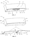
FIG. 1 is a perspective view of an apparatus, according to an embodiment of the disclosure. -
FIG. 2 is an expanded exploded view of a portion of the apparatus ofFIG. 1 , according to an embodiment of the disclosure. -
FIG. 3 is a cross section view of the interface between the first article and the second article ofFIG. 1 along line 3-3, according to an embodiment of the disclosure. -
FIG. 4 is a cross section view of the interface between the first article and the second article ofFIG. 1 along line 4-4, according to an embodiment of the disclosure. -
FIG. 5 is a cross section view of the interface between the first article and the second article ofFIG. 1 along line 5-5, according to an embodiment of the disclosure. -
FIG. 6 is a cross section view of a non-cooperating interface otherwise comparable to the interface between the first article and the second article ofFIG. 1 , for comparative purposes. - Wherever possible, the same reference numbers will be used throughout the drawings to represent the same parts.
- Provided is an article such as, but not limited to, a turbine component. Embodiments of the present disclosure, for example, in comparison to concepts failing to include one or more of the features disclosed herein, increase efficiency, increase durability, increase temperature tolerance, reduce overall cost reduce material cost, reduce the need for pressurizing a shroud or similar turbine component, increase required service intervals, produce other advantages, or a combination thereof.
- Referring to
FIGS. 1 and 2 , in one embodiment, anapparatus 10 includes afirst article 102, asecond article 104, and athird article 106. Thefirst article 102 includes at least one first ceramicmatrix composite ply 108, and is adjacent to a gas path 112 (not shown). Thesecond article 104 includes at least one second ceramicmatrix composite ply 110, and is adjacent to thegas path 112 and thefirst article 102. Thethird article 106 is adjacent to thefirst article 102 and thesecond article 104, with thefirst article 102 and thesecond article 104 being disposed between thethird article 106 and thegas path 112. The at least one first ceramicmatrix composite ply 108 and the at least one second ceramicmatrix composite ply 110 define aninterface 114. Theapparatus 10 may be any suitable apparatus, including, but not limited to, aturbine component 100. - Referring to
FIGS. 3-6 , theinterface 114 includes a firstcooperating feature 116 of the at least one first ceramicmatrix composite ply 108 and a secondcooperating feature 118 of the at least one second ceramicmatrix composite ply 110. The first cooperatingfeature 116 and the second cooperatingfeature 118 define a restricted flow path from thegas path 112 to the third article. Therestricted flow path 300 includes a reduced volumetric flow rate of a gas from thegas path 112 to thethird article 106 relative to a non-restrictedflow path 600 of a non-cooperatinginterface 602. - In one embodiment, the at least one first ceramic
matrix composite ply 108 consists of a single ply. In another embodiment, the at least one first ceramicmatrix composite ply 108 includes a plurality of plies. In one embodiment, the at least one second ceramicmatrix composite ply 110 consists of a single ply. In yet another embodiment, the at least one second ceramicmatrix composite ply 110 includes a plurality of plies. - Referring again to
FIG. 1 , thearticle 10 may be anysuitable turbine component 100, including, but not limited to, a shroud (shown), a turbine blade (bucket) shroud, a near flowpath seal, or a nozzle (vane) endwall. In one embodiment, wherein theturbine component 100 is a shroud, thefirst article 102 is a first inner shroud segment, thesecond article 104 is a second inner shroud segment, and thethird article 106 is an outer shroud. In a further embodiment, theinterface 114 is ahook segment 128 of theshroud 120. - The at least one first ceramic
matrix composite ply 108 and the at least one second ceramicmatrix composite ply 110 may independently include any suitable ceramic matrix composite composition, including, but not limited to, a ceramic matrix composite including reinforcing fibers wherein the reinforcing fibers may include, but are not limited to, silicon fibers, carbon fibers, silicon carbide fibers, SCS-6 silicon carbine monofilament fibers, rare-earth silicate fibers, silicon nitride fibers, aluminum oxide fibers, silica fibers, boron fibers, boron carbide fibers, aramid fibers, para-aramid fibers, KEVLAR™ para-aramid fibers, refractory metal fibers, superalloy fibers, silica-alumina-magnesia fibers, S-glass fibers, zirconium fibers, beryllium fibers, or a combination thereof, an aluminum oxide-fiber-reinforced aluminum oxide (Ox/Ox), a carbon-fiber-reinforced carbon (C/C), a carbon-fiber-reinforced silicon carbide (C/SiC), a silicon-carbide-fiber-reinforced silicon carbide (SiC/SiC), or a combination thereof. - The
third article 106 may include any suitable composition such as, but not limited to, a metallic composition. Suitable metallic compositions include, but are not limited to, a titanium alloy, an aluminum alloy, an aluminum-titanium-based alloy, a steel, a stainless steel, a nickel-based superalloy, an alloy suitable for turbine applications, or a combination thereof. - The
interface 114 may be any suitable interface which establishesrestricted flow path 300.Suitable interfaces 114 may include, but are not limited to, a bridle interface, a finger interface, a dovetail interface, a dado interface, a groove interface, a tongue and groove interface, a triangular tongue and groove interface, a mortise and tenon interface, a hammer-headed tenon interface, a scarf interface 302 (shown inFIG. 3 ), a plane scarf interface, a nibbed scarf interface, a splice interface, a half lap splice interface 400 (shown inFIG. 4 ), a bevel lap splice interface, a tabled splice interface, a tapered finger splice interface, a sawtooth interface, a chevron interface 500 (shown inFIG. 5 ), a sinusoidal interface, or a combination thereof. - The
interface 114 includes athickness 304. Thethickness 304 of theinterface 114 may be anysuitable thickness 304, including, but not limited to, athickness 304 of at least about 0.045 inches, alternatively at least about 0.06 inches, alternatively at least about 0.075 inches, alternatively less than about 0.4 inches, alternatively less than about 0.35 inches, alternatively less than about 0.3 inches, alternatively less than about 0.25 inches, alternatively less than about 0.2 inches, alternatively less than about 0.15 inches, alternatively less than about 0.1 inches, alternatively between about 0.045 inches to about 0.4 inches, alternatively between about 0.045 inches to about 0.3 inches, alternatively between about 0.045 inches to about 0.2 inches, alternatively between about 0.045 inches to about 0.1 inches. - Referring again to
FIG. 2 , in one embodiment, theinterface 114 includes acurved portion 200 having a curvature of at least about 45°, alternatively at least about 60°, alternatively at least about 75°, alternatively at least about 90°, alternatively at least about 105°, alternatively at least about 120°, alternatively at least about 180°, alternatively at least about 195°. Thecurved portion 200 includes a radius ofcurvature 202. The radius ofcurvature 202 may be any suitable radius, measured at a mean thickness along thecurved portion 200, including, but not limited to, a radius of less than about 0.5 inches, alternatively less than about 0.4 inches, alternatively less than about 0.3 inches, alternatively less than about 0.25 inches, alternatively less than about 0.2 inches, alternatively less than about 0.15 inches, alternatively less than about 0.1 inches. - Referring to
FIGS. 2 and 3-5 , in one embodiment, incorporation of the firstcooperating feature 116 and thesecond cooperative feature 118 to form theinterface 114 is operative to restrict flow from thegas path 112 to thethird article 106 wherein theinterface 114 includes acurved portion 200 having at least one of a curvature which is too severe and radius ofcurvature 202 which is too small, in combination with a thickness 304 (as shown inFIG. 3 ) which is too narrow, for a laminate seal to be inserted into theinterface 114 and be effective in restricting flow from thegas path 112 to thethird article 106. - Referring to
FIGS. 1-5 , in one embodiment a method for forming thearticle 10 includes forming the firstcooperating feature 116 into the at least one first ceramicmatrix composite ply 108 of thefirst article 102, and forming the secondcooperating feature 118 into the at least one second ceramicmatrix composite ply 110 of thesecond article 104. Thefirst article 102 is positioned adjacent to thesecond article 104, and thefirst article 102 and thesecond article 104 are positioned adjacent to thethird article 106. Thefirst article 102,second article 104, andthird article 106 are arranged and configured such that thefirst article 102 and thesecond article 104 are disposed between thethird article 106 and agas path 112. The first cooperatingfeature 116 is aligned with the second cooperatingfeature 118 to define theinterface 114 having the restrictedflow path 300 from thegas path 112 to thethird article 106. - Forming the first cooperating
feature 116 and the second cooperatingfeature 118 may include any suitable technique. In one embodiment, the first cooperatingfeature 116 is formed in the at least one first ceramic matrixcomposite ply 108 and the second cooperatingfeature 118 is formed in the at least one second ceramic matrixcomposite ply 110, wherein the at least one first ceramic matrixcomposite ply 108 and the at least one second ceramic matrixcomposite ply 110 are separate and distinct from one another when the first cooperatingfeature 116 and the second cooperating features 118 are formed. In another embodiment, at least one ceramic matrix composite ply is separated into the at least one first ceramic matrixcomposite ply 108 and the at least one second ceramic matrixcomposite ply 110, wherein separating the at least one first ceramic matrix composite ply 108 from the at least one second ceramic matrix composite ply 110 forms the first cooperatingfeature 116 and the second cooperatingfeature 118. Separating the at least one first ceramic matrix composite ply 108 from the at least one second ceramic matrixcomposite ply 110 may include any suitable severing technique, including, but not limited to cutting, milling, drilling, grinding, abrasive flow machining, abrasive jet machining, laser cutting, plasma cutting, water jet cutting, or a combination thereof - In one embodiment, forming the first cooperating
feature 116 and the second cooperatingfeature 118 includes at least one of machining the first cooperatingfeature 116 into the at least one first ceramic matrixcomposite ply 108 and machining the second cooperatingfeature 118 into the at least one second ceramic matrixcomposite ply 110. In a further embodiment, forming the first cooperatingfeature 116 and the second cooperatingfeature 118 includes machining the first cooperatingfeature 116 into the at least one first ceramic matrixcomposite ply 108 and machining the second cooperatingfeature 118 into the at least one second ceramic matrixcomposite ply 110. Machining may include any suitable technique, including, but not limited to, a severing technique, diamond grinding, electrical discharge machining, or a combination thereof. - In another embodiment, forming the first cooperating
feature 116 and the second cooperatingfeature 118 includes at least one of molding the at least one first ceramic matrixcomposite ply 108 to net shape including the first cooperatingfeature 116 and molding the at least one second ceramic matrixcomposite ply 110 to net shape including the second cooperatingfeature 118. In a further embodiment, forming the first cooperatingfeature 116 and the second cooperatingfeature 118 includes molding the at least one first ceramic matrixcomposite ply 108 to net shape including the first cooperatingfeature 116 and molding the at least one second ceramic matrixcomposite ply 110 to net shape including the second cooperatingfeature 118. - In yet another embodiment, forming the first cooperating
feature 116 and the second cooperatingfeature 118 includes at least one of printing the at least one first ceramic matrixcomposite ply 108 having the first cooperatingfeature 116 by a near net shape printing process and printing the at least one second ceramic matrixcomposite ply 110 having the second cooperatingfeature 118 by a near net shape printing process. In a further embodiment, forming the first cooperatingfeature 116 and the second cooperatingfeature 118 includes printing the at least one first ceramic matrixcomposite ply 108 having the first cooperatingfeature 116 by a near net shape printing process and printing the at least one second ceramic matrixcomposite ply 110 having the second cooperatingfeature 118 by a near net shape printing process. Printing may include any suitable ceramic matrix composite printing process, including, but not limited to extruding a coated pre-impregnated tow by a continuous filament fabrication process. In one embodiment, printing includes placing and orienting reinforcing fibers and from a fiber feeding print head. In a further embodiment, the fiber feeding print head is mounted on a gantry. - While the invention has been described with reference to one or more embodiments, it will be understood by those skilled in the art that various changes may be made and equivalents may be substituted for elements thereof without departing from the scope of the invention. In addition, many modifications may be made to adapt a particular situation or material to the teachings of the invention without departing from the essential scope thereof. Therefore, it is intended that the invention not be limited to the particular embodiment disclosed as the best mode contemplated for carrying out this invention, but that the invention will include all embodiments falling within the scope of the appended claims.
- Various aspects and embodiments of the present invention are defined by the following numbered clauses:
- 1. An apparatus, comprising:
- a first article including at least one first ceramic matrix composite ply, the first article being adjacent to a gas path;
- a second article including at least one second ceramic matrix composite ply, the second article being adjacent to the gas path and the first article; and
- a third article, the third article being adjacent to the first article and the second article, the first article and the second article being disposed between the third article and the gas path,
- wherein the at least one first ceramic matrix composite ply and the at least one second ceramic matrix composite ply define an interface, the interface including a first cooperating feature of the at least one first ceramic matrix composite ply and a second cooperating feature of the at least one second ceramic matrix composite ply, the first cooperating feature and the second cooperating feature defining a restricted flow path from the gas path to the third article, the restricted flow path including a reduced volumetric flow rate of a gas from the gas path to the third article relative to a non-restricted flow path of a non-cooperating interface.
- 2. The apparatus of clause 1, wherein the apparatus is a turbine component.
- 3. The apparatus of clause 2, wherein the turbine component is a shroud, the first article is a first inner shroud segment, the second article is a second inner shroud segment, and the third article is an outer shroud.
- 4. The apparatus of any preceding clause, wherein the interface is a hook segment of the shroud.
- 5. The apparatus of any preceding clause, wherein the at least one first ceramic matrix composite ply and the at least one second ceramic matrix composite ply independently include a ceramic matrix composite composition selected from the group consisting of:
- an aluminum oxide-fiber-reinforced aluminum oxide (Ox/Ox);
- a carbon-fiber-reinforced carbon (C/C);
- a carbon-fiber-reinforced silicon carbide (C/SiC);
- a silicon-carbide-fiber-reinforced silicon carbide (SiC/SiC);
- a ceramic matrix composite including reinforcing fibers selected from the group consisting of silicon fibers, carbon fibers, silicon carbide fibers, SCS-6 silicon carbine monofilament fibers, rare-earth silicate fibers, silicon nitride fibers, aluminum oxide fibers, silica fibers, boron fibers, boron carbide fibers, aramid fibers, para-aramid fibers, KEVLAR™ para-aramid fibers, refractory metal fibers, superalloy fibers, silica-alumina-magnesia fibers, S-glass fibers, zirconium fibers, beryllium fibers, and combinations thereof; and
- combinations thereof.
- 6. The apparatus of any preceding clause, wherein the third article includes a metallic composition.
- 7. The apparatus of any preceding clause, wherein the interface is selected from the group consisting of a bridle interface, a finger interface, a dovetail interface, a dado interface, a groove interface, a tongue and groove interface, a triangular tongue and groove interface, a mortise and tenon interface, a hammer-headed tenon interface, a scarf interface, a plane scarf interface, a nibbed scarf interface, a splice interface, a half lap splice interface, a bevel lap splice interface, a tabled splice interface, a tapered finger splice interface, a sawtooth interface, a chevron interface, a sinusoidal interface, and combinations thereof.
- 8. The apparatus of any preceding clause, wherein the interface includes a thickness of between about 0.045 inches to about 0.4 inches.
- 9. The apparatus of any preceding clause, wherein the interface includes a curved portion having a curvature of at least about 45°.
- 10. The apparatus of any preceding clause, wherein the curved portion includes a radius of curvature of less than about 0.5 inches, measured at a mean thickness along the curved portion.
- 11. A method for forming an apparatus, comprising:
- forming a first cooperating feature into at least one first ceramic matrix composite ply of a first article;
- forming a second cooperating feature into at least one second ceramic matrix composite ply of a second article;
- positioning the first article adjacent to the second article, and the first article and the second article adjacent to a third article, arranged and configured such that the first article and the second article are disposed between the third article and a gas path;
- aligning the first cooperating feature with the second cooperating feature to define an interface having a restricted flow path from the gas path to the third article, the restricted flow path including a reduced volumetric flow rate of a gas from the gas path to the third article relative to a non-restricted flow path of a non-cooperating interface.
- 12. The method of any preceding clause, wherein forming the article includes forming a turbine shroud as the article, positioning a first inner shroud segment as the first article, positioning a second inner shroud segment as the second article, and positioning an outer shroud as the third article.
- 13. The method of any preceding clause, wherein defining the interface includes defining a hook segment of the shroud.
- 14. The method of any preceding clause, wherein defining the interface includes defining the interface selected from the group consisting of a bridle interface, a finger interface, a dovetail interface, a dado interface, a groove interface, a tongue and groove interface, a triangular tongue and groove interface, a mortise and tenon interface, a hammer-headed tenon interface, a scarf interface, a plane scarf interface, a nibbed scarf interface, a splice interface, a half lap splice interface, a bevel lap splice interface, a tabled splice interface, a tapered finger splice interface, a sawtooth interface, a chevron interface, a sinusoidal interface, and combinations thereof.
- 15. The method of any preceding clause, wherein at least one of forming the first cooperating feature and forming the second cooperating feature includes at least one of machining the first cooperating feature into the at least one first ceramic matrix composite ply and machining the second cooperating feature into the at least one second ceramic matrix composite ply.
- 16. The method of any preceding clause, wherein at least one of forming the first cooperating feature and forming the second cooperating feature includes at least one of molding the at least one first ceramic matrix composite ply to net shape including the first cooperating feature and molding the at least one second ceramic matrix composite ply to net shape including the second cooperating feature.
- 17. The method of any preceding clause, wherein at least one of forming the first cooperating feature and forming the second cooperating feature includes at least one of printing the at least one first ceramic matrix composite ply having the first cooperating feature by a near net shape printing process and printing the at least one second ceramic matrix composite ply having the second cooperating feature by a near net shape printing process.
- 18. The method of any preceding clause, wherein defining the interface includes the interface having a thickness of between about 0.045 inches to about 0.4 inches.
- 19. The method of any preceding clause, wherein defining the interface includes the interface having a curved portion having a curvature of at least about 45°.
- 20. The method of any preceding clause, wherein defining the interface includes the interface having a radius of curvature of less than about 0.5 inches, measured at a mean thickness along the curved portion.
Claims (15)
- An apparatus (10), comprising:a first article (102) including at least one first ceramic matrix composite ply (108), the first article (102) being adjacent to a gas path (112);a second article (104) including at least one second ceramic matrix composite ply (110), the second article (104) being adjacent to the gas path (112) and the first article (102); anda third article (106), the third article (106) being adjacent to the first article (102) and the second article (104), the first article (102) and the second article (104) being disposed between the third article (106) and the gas path (112),wherein the at least one first ceramic matrix composite ply (108) and the at least one second ceramic matrix composite ply (110) define an interface (114), the interface (114) including a first cooperating feature (116) of the at least one first ceramic matrix composite ply (108) and a second cooperating feature (118) of the at least one second ceramic matrix composite ply (110), the first cooperating feature (116) and the second cooperating feature (118) defining a restricted flow path (300) from the gas path (112) to the third article (106), the restricted flow path (300) including a reduced volumetric flow rate of a gas from the gas path (112) to the third article (106) relative to a non-restricted flow path (600) of a non-cooperating interface (602).
- The apparatus (10) of claim 1, wherein the apparatus (10) is a turbine component (100) and the turbine component (100) is a shroud (120), the first article (102) is a first inner shroud segment (122), the second article (104) is a second inner shroud segment (124), and the third article (106) is an outer shroud (126).
- The apparatus (10) of any preceding claim, wherein the interface (114) is a hook segment (128) of the shroud (120).
- The apparatus of any preceding claim, wherein the at least one first ceramic matrix composite ply and the at least one second ceramic matrix composite ply independently include a ceramic matrix composite composition selected from the group consisting of:an aluminum oxide-fiber-reinforced aluminum oxide (Ox/Ox);a carbon-fiber-reinforced carbon (C/C);a carbon-fiber-reinforced silicon carbide (C/SiC);a silicon-carbide-fiber-reinforced silicon carbide (SiC/SiC);a ceramic matrix composite including reinforcing fibers selected from the group consisting of silicon fibers, carbon fibers, silicon carbide fibers, SCS-6 silicon carbine monofilament fibers, rare-earth silicate fibers, silicon nitride fibers, aluminum oxide fibers, silica fibers, boron fibers, boron carbide fibers, aramid fibers, para-aramid fibers, KEVLAR™ para-aramid fibers, refractory metal fibers, superalloy fibers, silica-alumina-magnesia fibers, S-glass fibers, zirconium fibers, beryllium fibers, and combinations thereof; andcombinations thereof.
- The apparatus of any preceding claim, wherein the third article includes a metallic composition.
- The apparatus (10) of any preceding claim, wherein the interface (114) is selected from the group consisting of a bridle interface, a finger interface, a dovetail interface, a dado interface, a groove interface, a tongue and groove interface, a triangular tongue and groove interface, a mortise and tenon interface, a hammer-headed tenon interface, a scarf interface (302), a plane scarf interface, a nibbed scarf interface, a splice interface, a half lap splice interface (400), a bevel lap splice interface, a tabled splice interface, a tapered finger splice interface, a sawtooth interface, a chevron interface (500), a sinusoidal interface, and combinations thereof.
- The apparatus (10) of any preceding claim, wherein the interface (114) includes a thickness (304) of between about 0.045 inches to about 0.4 inches.
- The apparatus (10) of any preceding claim, wherein the interface (114) includes a curved portion (200) having a curvature of at least about 45°.
- The apparatus (10) of claim 8, wherein the curved portion (200) includes a radius of curvature (202) of less than about 0.5 inches, measured at a mean thickness along the curved portion (200).
- A method for forming an apparatus (10), comprising:forming a first cooperating feature (116) into at least one first ceramic matrix composite ply (108) of a first article (102);forming a second cooperating feature (118) into at least one second ceramic matrix composite ply (110) of a second article (104);positioning the first article (102) adjacent to the second article (104), and the first article (102) and the second article (104) adjacent to a third article (106), arranged and configured such that the first article (102) and the second article (104) are disposed between the third article (106) and a gas path (112);aligning the first cooperating feature (116) with the second cooperating feature (118) to define an interface (114) having a restricted flow path (300) from the gas path (112) to the third article (106), the restricted flow path (300) including a reduced volumetric flow rate of a gas from the gas path (112) to the third article (106) relative to a non-restricted flow path (600) of a non-cooperating interface (606).
- The method of claim 10, wherein forming the article includes forming a turbine shroud as the article, positioning a first inner shroud segment as the first article, positioning a second inner shroud segment as the second article, and positioning an outer shroud as the third article.
- The method of claim 10 or claim 11, wherein defining the interface includes defining a hook segment of the shroud.
- The method of any of claims 10 to 12, wherein defining the interface includes defining the interface selected from the group consisting of a bridle interface, a finger interface, a dovetail interface, a dado interface, a groove interface, a tongue and groove interface, a triangular tongue and groove interface, a mortise and tenon interface, a hammer-headed tenon interface, a scarf interface, a plane scarf interface, a nibbed scarf interface, a splice interface, a half lap splice interface, a bevel lap splice interface, a tabled splice interface, a tapered finger splice interface, a sawtooth interface, a chevron interface, a sinusoidal interface, and combinations thereof.
- The method of any of claims 10 to 13, wherein defining the interface (114) includes the interface (114) having a curved portion (200) having a curvature of at least about 45°.
- The method of any of claims 10 to 14, wherein defining the interface (114) includes the interface (114) having a radius of curvature (202) of less than about 0.5 inches, measured at a mean thickness along the curved portion (200).
Applications Claiming Priority (1)
| Application Number | Priority Date | Filing Date | Title |
|---|---|---|---|
| US15/079,346 US20170276000A1 (en) | 2016-03-24 | 2016-03-24 | Apparatus and method for forming apparatus |
Publications (2)
| Publication Number | Publication Date |
|---|---|
| EP3228829A1 true EP3228829A1 (en) | 2017-10-11 |
| EP3228829B1 EP3228829B1 (en) | 2020-07-08 |
Family
ID=58412947
Family Applications (1)
| Application Number | Title | Priority Date | Filing Date |
|---|---|---|---|
| EP17162635.1A Active EP3228829B1 (en) | 2016-03-24 | 2017-03-23 | Apparatus and method for forming apparatus |
Country Status (3)
| Country | Link |
|---|---|
| US (1) | US20170276000A1 (en) |
| EP (1) | EP3228829B1 (en) |
| JP (1) | JP7102101B2 (en) |
Cited By (5)
| Publication number | Priority date | Publication date | Assignee | Title |
|---|---|---|---|---|
| EP3767077A1 (en) * | 2019-07-19 | 2021-01-20 | Raytheon Technologies Corporation | Cmc boas arrangement |
| US11073037B2 (en) | 2019-07-19 | 2021-07-27 | Raytheon Technologies Corporation | CMC BOAS arrangement |
| US11073038B2 (en) | 2019-07-19 | 2021-07-27 | Raytheon Technologies Corporation | CMC BOAS arrangement |
| US11248482B2 (en) | 2019-07-19 | 2022-02-15 | Raytheon Technologies Corporation | CMC BOAS arrangement |
| EP4442671A1 (en) * | 2023-04-06 | 2024-10-09 | RTX Corporation | Method for manufacturing multiple seal arc segments |
Families Citing this family (3)
| Publication number | Priority date | Publication date | Assignee | Title |
|---|---|---|---|---|
| ES2769074T3 (en) * | 2017-06-01 | 2020-06-24 | MTU Aero Engines AG | Intermediate housing for turbine with centering element |
| US11359505B2 (en) * | 2019-05-04 | 2022-06-14 | Raytheon Technologies Corporation | Nesting CMC components |
| US12320258B2 (en) * | 2022-11-18 | 2025-06-03 | Rtx Corporation | Blade outer air seal with large radius of curvature mount hooks |
Citations (4)
| Publication number | Priority date | Publication date | Assignee | Title |
|---|---|---|---|---|
| US6425738B1 (en) * | 2000-05-11 | 2002-07-30 | General Electric Company | Accordion nozzle |
| EP1431518A2 (en) * | 2002-12-20 | 2004-06-23 | General Electric Company | Turbine engine shroud segment assembly with a surface-recessed seal bridging adjacent shroud segments |
| US20090148277A1 (en) * | 2007-12-05 | 2009-06-11 | United Technologies Corp. | Gas Turbine Engines and Related Systems Involving Blade Outer Air Seals |
| EP3054105A1 (en) * | 2015-02-03 | 2016-08-10 | General Electric Company | Component, gas turbine component and corresponding method of forming |
Family Cites Families (25)
| Publication number | Priority date | Publication date | Assignee | Title |
|---|---|---|---|---|
| US5071313A (en) * | 1990-01-16 | 1991-12-10 | General Electric Company | Rotor blade shroud segment |
| US5456576A (en) * | 1994-08-31 | 1995-10-10 | United Technologies Corporation | Dynamic control of tip clearance |
| US6702550B2 (en) * | 2002-01-16 | 2004-03-09 | General Electric Company | Turbine shroud segment and shroud assembly |
| US6733235B2 (en) * | 2002-03-28 | 2004-05-11 | General Electric Company | Shroud segment and assembly for a turbine engine |
| JP2004036443A (en) * | 2002-07-02 | 2004-02-05 | Ishikawajima Harima Heavy Ind Co Ltd | Gas turbine shroud structure |
| US6758653B2 (en) * | 2002-09-09 | 2004-07-06 | Siemens Westinghouse Power Corporation | Ceramic matrix composite component for a gas turbine engine |
| US6910854B2 (en) * | 2002-10-08 | 2005-06-28 | United Technologies Corporation | Leak resistant vane cluster |
| US7052235B2 (en) * | 2004-06-08 | 2006-05-30 | General Electric Company | Turbine engine shroud segment, hanger and assembly |
| US7278820B2 (en) * | 2005-10-04 | 2007-10-09 | Siemens Power Generation, Inc. | Ring seal system with reduced cooling requirements |
| US8303245B2 (en) * | 2009-10-09 | 2012-11-06 | General Electric Company | Shroud assembly with discourager |
| JP5495941B2 (en) * | 2010-05-21 | 2014-05-21 | 三菱重工業株式会社 | Turbine split ring, gas turbine including the same, and power plant including the same |
| US8944756B2 (en) * | 2011-07-15 | 2015-02-03 | United Technologies Corporation | Blade outer air seal assembly |
| US9136629B2 (en) * | 2012-07-19 | 2015-09-15 | Holland Electronics, Llc | Moving part coaxial cable connectors |
| US9316109B2 (en) * | 2012-04-10 | 2016-04-19 | General Electric Company | Turbine shroud assembly and method of forming |
| US9260788B2 (en) * | 2012-10-30 | 2016-02-16 | General Electric Company | Reinforced articles and methods of making the same |
| US9863264B2 (en) * | 2012-12-10 | 2018-01-09 | General Electric Company | Turbine shroud engagement arrangement and method |
| CA2897965C (en) * | 2013-03-11 | 2020-02-25 | Rolls-Royce Corporation | Compliant intermediate component of a gas turbine engine |
| WO2015138027A2 (en) * | 2013-12-17 | 2015-09-17 | United Technologies Corporation | Meter plate for blade outer air seal |
| US8939716B1 (en) * | 2014-02-25 | 2015-01-27 | Siemens Aktiengesellschaft | Turbine abradable layer with nested loop groove pattern |
| US20150345308A1 (en) * | 2014-06-02 | 2015-12-03 | General Electric Company | Turbine component |
| US9784116B2 (en) * | 2015-01-15 | 2017-10-10 | General Electric Company | Turbine shroud assembly |
| US20160319690A1 (en) * | 2015-04-30 | 2016-11-03 | General Electric Company | Additive manufacturing methods for turbine shroud seal structures |
| EP3088679A1 (en) * | 2015-04-30 | 2016-11-02 | Rolls-Royce Corporation | Seal for a gas turbine engine assembly |
| US9745849B2 (en) * | 2015-06-26 | 2017-08-29 | General Electric Company | Methods for treating field operated components |
| US11193392B2 (en) * | 2016-03-21 | 2021-12-07 | General Electric Company | CMC ply overlap ingestion restrictor |
-
2016
- 2016-03-24 US US15/079,346 patent/US20170276000A1/en not_active Abandoned
-
2017
- 2017-03-10 JP JP2017045538A patent/JP7102101B2/en active Active
- 2017-03-23 EP EP17162635.1A patent/EP3228829B1/en active Active
Patent Citations (4)
| Publication number | Priority date | Publication date | Assignee | Title |
|---|---|---|---|---|
| US6425738B1 (en) * | 2000-05-11 | 2002-07-30 | General Electric Company | Accordion nozzle |
| EP1431518A2 (en) * | 2002-12-20 | 2004-06-23 | General Electric Company | Turbine engine shroud segment assembly with a surface-recessed seal bridging adjacent shroud segments |
| US20090148277A1 (en) * | 2007-12-05 | 2009-06-11 | United Technologies Corp. | Gas Turbine Engines and Related Systems Involving Blade Outer Air Seals |
| EP3054105A1 (en) * | 2015-02-03 | 2016-08-10 | General Electric Company | Component, gas turbine component and corresponding method of forming |
Cited By (6)
| Publication number | Priority date | Publication date | Assignee | Title |
|---|---|---|---|---|
| EP3767077A1 (en) * | 2019-07-19 | 2021-01-20 | Raytheon Technologies Corporation | Cmc boas arrangement |
| US11073037B2 (en) | 2019-07-19 | 2021-07-27 | Raytheon Technologies Corporation | CMC BOAS arrangement |
| US11073038B2 (en) | 2019-07-19 | 2021-07-27 | Raytheon Technologies Corporation | CMC BOAS arrangement |
| US11105214B2 (en) | 2019-07-19 | 2021-08-31 | Raytheon Technologies Corporation | CMC BOAS arrangement |
| US11248482B2 (en) | 2019-07-19 | 2022-02-15 | Raytheon Technologies Corporation | CMC BOAS arrangement |
| EP4442671A1 (en) * | 2023-04-06 | 2024-10-09 | RTX Corporation | Method for manufacturing multiple seal arc segments |
Also Published As
| Publication number | Publication date |
|---|---|
| US20170276000A1 (en) | 2017-09-28 |
| EP3228829B1 (en) | 2020-07-08 |
| JP7102101B2 (en) | 2022-07-19 |
| JP2017172584A (en) | 2017-09-28 |
Similar Documents
| Publication | Publication Date | Title |
|---|---|---|
| EP3228829B1 (en) | Apparatus and method for forming apparatus | |
| CN103291387B (en) | Shield segment used for fuel gas turbine engine and shield equipment including same | |
| US9175579B2 (en) | Low-ductility turbine shroud | |
| RU2616335C2 (en) | Turbine element of gas turbine engine with microchannel cooling (versions) | |
| JP6981724B2 (en) | High temperature gas path component cooling system with particle collection chamber | |
| US9745849B2 (en) | Methods for treating field operated components | |
| EP3736414B1 (en) | Abrasive tip blade and manufacture method | |
| US20160069195A1 (en) | Rotary blade tip | |
| EP3150801A1 (en) | Cmc film cooled gas turbine engine component | |
| US20160010488A1 (en) | Wear protection arrangement for a turbomachine, process and compressor | |
| US11021971B2 (en) | CMC blade with monolithic ceramic platform and dovetail | |
| US20190076930A1 (en) | Method for manufacturing an abradable plate and repairing a turbine shroud | |
| US20150345388A1 (en) | Gas turbine component and process for producing gas turbine component | |
| US10662786B2 (en) | CMC articles having small complex features for advanced film cooling | |
| US20170089578A1 (en) | Cmc articles having small complex features for advanced film cooling | |
| EP3739175B1 (en) | Ceramic matrix composite aerofoil with impact reinforcements | |
| US20180087387A1 (en) | Compositions and methods for coating metal turbine blade tips | |
| US20220275728A1 (en) | Three-dimensional ceramic matrix composite t-joint for airfoils via pin-weaving | |
| EP4293201B1 (en) | Seal system for a gas turbine engine, gas turbine engine and method for manufacture, repair or replacement of a seal system | |
| US10533432B2 (en) | Preform CMC article, CMC article, and method for forming CMC article | |
| EP2876259B1 (en) | Turbine buckets with high hot hardness shroud-cutting deposits | |
| US12385405B2 (en) | Wear resistant article and method of making | |
| US20180156046A1 (en) | Rotor blade for a gas turbine | |
| KR20200031637A (en) | Standalone ceramic seal for gas turbine | |
| US11401834B2 (en) | Method of securing a ceramic matrix composite (CMC) component to a metallic substructure using CMC straps |
Legal Events
| Date | Code | Title | Description |
|---|---|---|---|
| PUAI | Public reference made under article 153(3) epc to a published international application that has entered the european phase |
Free format text: ORIGINAL CODE: 0009012 |
|
| STAA | Information on the status of an ep patent application or granted ep patent |
Free format text: STATUS: THE APPLICATION HAS BEEN PUBLISHED |
|
| AK | Designated contracting states |
Kind code of ref document: A1 Designated state(s): AL AT BE BG CH CY CZ DE DK EE ES FI FR GB GR HR HU IE IS IT LI LT LU LV MC MK MT NL NO PL PT RO RS SE SI SK SM TR |
|
| AX | Request for extension of the european patent |
Extension state: BA ME |
|
| STAA | Information on the status of an ep patent application or granted ep patent |
Free format text: STATUS: REQUEST FOR EXAMINATION WAS MADE |
|
| 17P | Request for examination filed |
Effective date: 20180411 |
|
| RBV | Designated contracting states (corrected) |
Designated state(s): AL AT BE BG CH CY CZ DE DK EE ES FI FR GB GR HR HU IE IS IT LI LT LU LV MC MK MT NL NO PL PT RO RS SE SI SK SM TR |
|
| GRAP | Despatch of communication of intention to grant a patent |
Free format text: ORIGINAL CODE: EPIDOSNIGR1 |
|
| STAA | Information on the status of an ep patent application or granted ep patent |
Free format text: STATUS: GRANT OF PATENT IS INTENDED |
|
| INTG | Intention to grant announced |
Effective date: 20200211 |
|
| GRAS | Grant fee paid |
Free format text: ORIGINAL CODE: EPIDOSNIGR3 |
|
| GRAA | (expected) grant |
Free format text: ORIGINAL CODE: 0009210 |
|
| STAA | Information on the status of an ep patent application or granted ep patent |
Free format text: STATUS: THE PATENT HAS BEEN GRANTED |
|
| AK | Designated contracting states |
Kind code of ref document: B1 Designated state(s): AL AT BE BG CH CY CZ DE DK EE ES FI FR GB GR HR HU IE IS IT LI LT LU LV MC MK MT NL NO PL PT RO RS SE SI SK SM TR |
|
| REG | Reference to a national code |
Ref country code: CH Ref legal event code: EP Ref country code: AT Ref legal event code: REF Ref document number: 1288669 Country of ref document: AT Kind code of ref document: T Effective date: 20200715 |
|
| REG | Reference to a national code |
Ref country code: DE Ref legal event code: R096 Ref document number: 602017019216 Country of ref document: DE |
|
| REG | Reference to a national code |
Ref country code: IE Ref legal event code: FG4D |
|
| REG | Reference to a national code |
Ref country code: LT Ref legal event code: MG4D |
|
| REG | Reference to a national code |
Ref country code: AT Ref legal event code: MK05 Ref document number: 1288669 Country of ref document: AT Kind code of ref document: T Effective date: 20200708 |
|
| REG | Reference to a national code |
Ref country code: NL Ref legal event code: MP Effective date: 20200708 |
|
| PG25 | Lapsed in a contracting state [announced via postgrant information from national office to epo] |
Ref country code: HR Free format text: LAPSE BECAUSE OF FAILURE TO SUBMIT A TRANSLATION OF THE DESCRIPTION OR TO PAY THE FEE WITHIN THE PRESCRIBED TIME-LIMIT Effective date: 20200708 Ref country code: PT Free format text: LAPSE BECAUSE OF FAILURE TO SUBMIT A TRANSLATION OF THE DESCRIPTION OR TO PAY THE FEE WITHIN THE PRESCRIBED TIME-LIMIT Effective date: 20201109 Ref country code: BG Free format text: LAPSE BECAUSE OF FAILURE TO SUBMIT A TRANSLATION OF THE DESCRIPTION OR TO PAY THE FEE WITHIN THE PRESCRIBED TIME-LIMIT Effective date: 20201008 Ref country code: LT Free format text: LAPSE BECAUSE OF FAILURE TO SUBMIT A TRANSLATION OF THE DESCRIPTION OR TO PAY THE FEE WITHIN THE PRESCRIBED TIME-LIMIT Effective date: 20200708 Ref country code: ES Free format text: LAPSE BECAUSE OF FAILURE TO SUBMIT A TRANSLATION OF THE DESCRIPTION OR TO PAY THE FEE WITHIN THE PRESCRIBED TIME-LIMIT Effective date: 20200708 Ref country code: NO Free format text: LAPSE BECAUSE OF FAILURE TO SUBMIT A TRANSLATION OF THE DESCRIPTION OR TO PAY THE FEE WITHIN THE PRESCRIBED TIME-LIMIT Effective date: 20201008 Ref country code: AT Free format text: LAPSE BECAUSE OF FAILURE TO SUBMIT A TRANSLATION OF THE DESCRIPTION OR TO PAY THE FEE WITHIN THE PRESCRIBED TIME-LIMIT Effective date: 20200708 Ref country code: SE Free format text: LAPSE BECAUSE OF FAILURE TO SUBMIT A TRANSLATION OF THE DESCRIPTION OR TO PAY THE FEE WITHIN THE PRESCRIBED TIME-LIMIT Effective date: 20200708 Ref country code: GR Free format text: LAPSE BECAUSE OF FAILURE TO SUBMIT A TRANSLATION OF THE DESCRIPTION OR TO PAY THE FEE WITHIN THE PRESCRIBED TIME-LIMIT Effective date: 20201009 Ref country code: FI Free format text: LAPSE BECAUSE OF FAILURE TO SUBMIT A TRANSLATION OF THE DESCRIPTION OR TO PAY THE FEE WITHIN THE PRESCRIBED TIME-LIMIT Effective date: 20200708 |
|
| PG25 | Lapsed in a contracting state [announced via postgrant information from national office to epo] |
Ref country code: PL Free format text: LAPSE BECAUSE OF FAILURE TO SUBMIT A TRANSLATION OF THE DESCRIPTION OR TO PAY THE FEE WITHIN THE PRESCRIBED TIME-LIMIT Effective date: 20200708 Ref country code: LV Free format text: LAPSE BECAUSE OF FAILURE TO SUBMIT A TRANSLATION OF THE DESCRIPTION OR TO PAY THE FEE WITHIN THE PRESCRIBED TIME-LIMIT Effective date: 20200708 Ref country code: RS Free format text: LAPSE BECAUSE OF FAILURE TO SUBMIT A TRANSLATION OF THE DESCRIPTION OR TO PAY THE FEE WITHIN THE PRESCRIBED TIME-LIMIT Effective date: 20200708 Ref country code: IS Free format text: LAPSE BECAUSE OF FAILURE TO SUBMIT A TRANSLATION OF THE DESCRIPTION OR TO PAY THE FEE WITHIN THE PRESCRIBED TIME-LIMIT Effective date: 20201108 |
|
| PG25 | Lapsed in a contracting state [announced via postgrant information from national office to epo] |
Ref country code: NL Free format text: LAPSE BECAUSE OF FAILURE TO SUBMIT A TRANSLATION OF THE DESCRIPTION OR TO PAY THE FEE WITHIN THE PRESCRIBED TIME-LIMIT Effective date: 20200708 |
|
| REG | Reference to a national code |
Ref country code: DE Ref legal event code: R097 Ref document number: 602017019216 Country of ref document: DE |
|
| PG25 | Lapsed in a contracting state [announced via postgrant information from national office to epo] |
Ref country code: SM Free format text: LAPSE BECAUSE OF FAILURE TO SUBMIT A TRANSLATION OF THE DESCRIPTION OR TO PAY THE FEE WITHIN THE PRESCRIBED TIME-LIMIT Effective date: 20200708 Ref country code: IT Free format text: LAPSE BECAUSE OF FAILURE TO SUBMIT A TRANSLATION OF THE DESCRIPTION OR TO PAY THE FEE WITHIN THE PRESCRIBED TIME-LIMIT Effective date: 20200708 Ref country code: EE Free format text: LAPSE BECAUSE OF FAILURE TO SUBMIT A TRANSLATION OF THE DESCRIPTION OR TO PAY THE FEE WITHIN THE PRESCRIBED TIME-LIMIT Effective date: 20200708 Ref country code: RO Free format text: LAPSE BECAUSE OF FAILURE TO SUBMIT A TRANSLATION OF THE DESCRIPTION OR TO PAY THE FEE WITHIN THE PRESCRIBED TIME-LIMIT Effective date: 20200708 Ref country code: CZ Free format text: LAPSE BECAUSE OF FAILURE TO SUBMIT A TRANSLATION OF THE DESCRIPTION OR TO PAY THE FEE WITHIN THE PRESCRIBED TIME-LIMIT Effective date: 20200708 Ref country code: DK Free format text: LAPSE BECAUSE OF FAILURE TO SUBMIT A TRANSLATION OF THE DESCRIPTION OR TO PAY THE FEE WITHIN THE PRESCRIBED TIME-LIMIT Effective date: 20200708 |
|
| PLBE | No opposition filed within time limit |
Free format text: ORIGINAL CODE: 0009261 |
|
| STAA | Information on the status of an ep patent application or granted ep patent |
Free format text: STATUS: NO OPPOSITION FILED WITHIN TIME LIMIT |
|
| PG25 | Lapsed in a contracting state [announced via postgrant information from national office to epo] |
Ref country code: AL Free format text: LAPSE BECAUSE OF FAILURE TO SUBMIT A TRANSLATION OF THE DESCRIPTION OR TO PAY THE FEE WITHIN THE PRESCRIBED TIME-LIMIT Effective date: 20200708 |
|
| 26N | No opposition filed |
Effective date: 20210409 |
|
| PG25 | Lapsed in a contracting state [announced via postgrant information from national office to epo] |
Ref country code: SK Free format text: LAPSE BECAUSE OF FAILURE TO SUBMIT A TRANSLATION OF THE DESCRIPTION OR TO PAY THE FEE WITHIN THE PRESCRIBED TIME-LIMIT Effective date: 20200708 |
|
| PG25 | Lapsed in a contracting state [announced via postgrant information from national office to epo] |
Ref country code: SI Free format text: LAPSE BECAUSE OF FAILURE TO SUBMIT A TRANSLATION OF THE DESCRIPTION OR TO PAY THE FEE WITHIN THE PRESCRIBED TIME-LIMIT Effective date: 20200708 |
|
| PG25 | Lapsed in a contracting state [announced via postgrant information from national office to epo] |
Ref country code: MC Free format text: LAPSE BECAUSE OF FAILURE TO SUBMIT A TRANSLATION OF THE DESCRIPTION OR TO PAY THE FEE WITHIN THE PRESCRIBED TIME-LIMIT Effective date: 20200708 |
|
| REG | Reference to a national code |
Ref country code: CH Ref legal event code: PL |
|
| GBPC | Gb: european patent ceased through non-payment of renewal fee |
Effective date: 20210323 |
|
| REG | Reference to a national code |
Ref country code: BE Ref legal event code: MM Effective date: 20210331 |
|
| PG25 | Lapsed in a contracting state [announced via postgrant information from national office to epo] |
Ref country code: GB Free format text: LAPSE BECAUSE OF NON-PAYMENT OF DUE FEES Effective date: 20210323 Ref country code: IE Free format text: LAPSE BECAUSE OF NON-PAYMENT OF DUE FEES Effective date: 20210323 Ref country code: FR Free format text: LAPSE BECAUSE OF NON-PAYMENT OF DUE FEES Effective date: 20210331 Ref country code: CH Free format text: LAPSE BECAUSE OF NON-PAYMENT OF DUE FEES Effective date: 20210331 Ref country code: LI Free format text: LAPSE BECAUSE OF NON-PAYMENT OF DUE FEES Effective date: 20210331 Ref country code: LU Free format text: LAPSE BECAUSE OF NON-PAYMENT OF DUE FEES Effective date: 20210323 |
|
| PG25 | Lapsed in a contracting state [announced via postgrant information from national office to epo] |
Ref country code: BE Free format text: LAPSE BECAUSE OF NON-PAYMENT OF DUE FEES Effective date: 20210331 |
|
| PG25 | Lapsed in a contracting state [announced via postgrant information from national office to epo] |
Ref country code: HU Free format text: LAPSE BECAUSE OF FAILURE TO SUBMIT A TRANSLATION OF THE DESCRIPTION OR TO PAY THE FEE WITHIN THE PRESCRIBED TIME-LIMIT; INVALID AB INITIO Effective date: 20170323 |
|
| PG25 | Lapsed in a contracting state [announced via postgrant information from national office to epo] |
Ref country code: CY Free format text: LAPSE BECAUSE OF FAILURE TO SUBMIT A TRANSLATION OF THE DESCRIPTION OR TO PAY THE FEE WITHIN THE PRESCRIBED TIME-LIMIT Effective date: 20200708 |
|
| REG | Reference to a national code |
Ref country code: DE Ref legal event code: R081 Ref document number: 602017019216 Country of ref document: DE Owner name: GENERAL ELECTRIC TECHNOLOGY GMBH, CH Free format text: FORMER OWNER: GENERAL ELECTRIC COMPANY, SCHENECTADY, NY, US |
|
| PG25 | Lapsed in a contracting state [announced via postgrant information from national office to epo] |
Ref country code: MK Free format text: LAPSE BECAUSE OF FAILURE TO SUBMIT A TRANSLATION OF THE DESCRIPTION OR TO PAY THE FEE WITHIN THE PRESCRIBED TIME-LIMIT Effective date: 20200708 |
|
| PG25 | Lapsed in a contracting state [announced via postgrant information from national office to epo] |
Ref country code: MT Free format text: LAPSE BECAUSE OF FAILURE TO SUBMIT A TRANSLATION OF THE DESCRIPTION OR TO PAY THE FEE WITHIN THE PRESCRIBED TIME-LIMIT Effective date: 20200708 |
|
| PG25 | Lapsed in a contracting state [announced via postgrant information from national office to epo] |
Ref country code: TR Free format text: LAPSE BECAUSE OF FAILURE TO SUBMIT A TRANSLATION OF THE DESCRIPTION OR TO PAY THE FEE WITHIN THE PRESCRIBED TIME-LIMIT Effective date: 20200708 |
|
| PGFP | Annual fee paid to national office [announced via postgrant information from national office to epo] |
Ref country code: DE Payment date: 20260219 Year of fee payment: 10 |