EP3228585A1 - Structural fibre-reinforced component with lightning strike protection by using carbon nano tube mats and metallic layers - Google Patents
Structural fibre-reinforced component with lightning strike protection by using carbon nano tube mats and metallic layers Download PDFInfo
- Publication number
- EP3228585A1 EP3228585A1 EP16164424.0A EP16164424A EP3228585A1 EP 3228585 A1 EP3228585 A1 EP 3228585A1 EP 16164424 A EP16164424 A EP 16164424A EP 3228585 A1 EP3228585 A1 EP 3228585A1
- Authority
- EP
- European Patent Office
- Prior art keywords
- carbon nano
- nano tube
- component
- tube mat
- metallic layer
- Prior art date
- Legal status (The legal status is an assumption and is not a legal conclusion. Google has not performed a legal analysis and makes no representation as to the accuracy of the status listed.)
- Granted
Links
Images


Classifications
-
- B—PERFORMING OPERATIONS; TRANSPORTING
- B32—LAYERED PRODUCTS
- B32B—LAYERED PRODUCTS, i.e. PRODUCTS BUILT-UP OF STRATA OF FLAT OR NON-FLAT, e.g. CELLULAR OR HONEYCOMB, FORM
- B32B5/00—Layered products characterised by the non- homogeneity or physical structure, i.e. comprising a fibrous, filamentary, particulate or foam layer; Layered products characterised by having a layer differing constitutionally or physically in different parts
- B32B5/02—Layered products characterised by the non- homogeneity or physical structure, i.e. comprising a fibrous, filamentary, particulate or foam layer; Layered products characterised by having a layer differing constitutionally or physically in different parts characterised by structural features of a fibrous or filamentary layer
- B32B5/022—Non-woven fabric
-
- B—PERFORMING OPERATIONS; TRANSPORTING
- B29—WORKING OF PLASTICS; WORKING OF SUBSTANCES IN A PLASTIC STATE IN GENERAL
- B29C—SHAPING OR JOINING OF PLASTICS; SHAPING OF MATERIAL IN A PLASTIC STATE, NOT OTHERWISE PROVIDED FOR; AFTER-TREATMENT OF THE SHAPED PRODUCTS, e.g. REPAIRING
- B29C70/00—Shaping composites, i.e. plastics material comprising reinforcements, fillers or preformed parts, e.g. inserts
- B29C70/02—Shaping composites, i.e. plastics material comprising reinforcements, fillers or preformed parts, e.g. inserts comprising combinations of reinforcements, e.g. non-specified reinforcements, fibrous reinforcing inserts and fillers, e.g. particulate fillers, incorporated in matrix material, forming one or more layers and with or without non-reinforced or non-filled layers
- B29C70/021—Combinations of fibrous reinforcement and non-fibrous material
-
- B—PERFORMING OPERATIONS; TRANSPORTING
- B29—WORKING OF PLASTICS; WORKING OF SUBSTANCES IN A PLASTIC STATE IN GENERAL
- B29C—SHAPING OR JOINING OF PLASTICS; SHAPING OF MATERIAL IN A PLASTIC STATE, NOT OTHERWISE PROVIDED FOR; AFTER-TREATMENT OF THE SHAPED PRODUCTS, e.g. REPAIRING
- B29C70/00—Shaping composites, i.e. plastics material comprising reinforcements, fillers or preformed parts, e.g. inserts
- B29C70/88—Shaping composites, i.e. plastics material comprising reinforcements, fillers or preformed parts, e.g. inserts characterised primarily by possessing specific properties, e.g. electrically conductive or locally reinforced
- B29C70/882—Shaping composites, i.e. plastics material comprising reinforcements, fillers or preformed parts, e.g. inserts characterised primarily by possessing specific properties, e.g. electrically conductive or locally reinforced partly or totally electrically conductive, e.g. for EMI shielding
- B29C70/885—Shaping composites, i.e. plastics material comprising reinforcements, fillers or preformed parts, e.g. inserts characterised primarily by possessing specific properties, e.g. electrically conductive or locally reinforced partly or totally electrically conductive, e.g. for EMI shielding with incorporated metallic wires, nets, films or plates
-
- B—PERFORMING OPERATIONS; TRANSPORTING
- B32—LAYERED PRODUCTS
- B32B—LAYERED PRODUCTS, i.e. PRODUCTS BUILT-UP OF STRATA OF FLAT OR NON-FLAT, e.g. CELLULAR OR HONEYCOMB, FORM
- B32B15/00—Layered products comprising a layer of metal
- B32B15/04—Layered products comprising a layer of metal comprising metal as the main or only constituent of a layer, which is next to another layer of the same or of a different material
- B32B15/08—Layered products comprising a layer of metal comprising metal as the main or only constituent of a layer, which is next to another layer of the same or of a different material of synthetic resin
-
- B—PERFORMING OPERATIONS; TRANSPORTING
- B32—LAYERED PRODUCTS
- B32B—LAYERED PRODUCTS, i.e. PRODUCTS BUILT-UP OF STRATA OF FLAT OR NON-FLAT, e.g. CELLULAR OR HONEYCOMB, FORM
- B32B15/00—Layered products comprising a layer of metal
- B32B15/14—Layered products comprising a layer of metal next to a fibrous or filamentary layer
-
- B—PERFORMING OPERATIONS; TRANSPORTING
- B32—LAYERED PRODUCTS
- B32B—LAYERED PRODUCTS, i.e. PRODUCTS BUILT-UP OF STRATA OF FLAT OR NON-FLAT, e.g. CELLULAR OR HONEYCOMB, FORM
- B32B15/00—Layered products comprising a layer of metal
- B32B15/18—Layered products comprising a layer of metal comprising iron or steel
-
- B—PERFORMING OPERATIONS; TRANSPORTING
- B32—LAYERED PRODUCTS
- B32B—LAYERED PRODUCTS, i.e. PRODUCTS BUILT-UP OF STRATA OF FLAT OR NON-FLAT, e.g. CELLULAR OR HONEYCOMB, FORM
- B32B15/00—Layered products comprising a layer of metal
- B32B15/20—Layered products comprising a layer of metal comprising aluminium or copper
-
- B—PERFORMING OPERATIONS; TRANSPORTING
- B32—LAYERED PRODUCTS
- B32B—LAYERED PRODUCTS, i.e. PRODUCTS BUILT-UP OF STRATA OF FLAT OR NON-FLAT, e.g. CELLULAR OR HONEYCOMB, FORM
- B32B27/00—Layered products comprising a layer of synthetic resin
- B32B27/12—Layered products comprising a layer of synthetic resin next to a fibrous or filamentary layer
-
- B—PERFORMING OPERATIONS; TRANSPORTING
- B32—LAYERED PRODUCTS
- B32B—LAYERED PRODUCTS, i.e. PRODUCTS BUILT-UP OF STRATA OF FLAT OR NON-FLAT, e.g. CELLULAR OR HONEYCOMB, FORM
- B32B27/00—Layered products comprising a layer of synthetic resin
- B32B27/30—Layered products comprising a layer of synthetic resin comprising vinyl (co)polymers; comprising acrylic (co)polymers
- B32B27/308—Layered products comprising a layer of synthetic resin comprising vinyl (co)polymers; comprising acrylic (co)polymers comprising acrylic (co)polymers
-
- B—PERFORMING OPERATIONS; TRANSPORTING
- B32—LAYERED PRODUCTS
- B32B—LAYERED PRODUCTS, i.e. PRODUCTS BUILT-UP OF STRATA OF FLAT OR NON-FLAT, e.g. CELLULAR OR HONEYCOMB, FORM
- B32B37/00—Methods or apparatus for laminating, e.g. by curing or by ultrasonic bonding
- B32B37/14—Methods or apparatus for laminating, e.g. by curing or by ultrasonic bonding characterised by the properties of the layers
-
- B—PERFORMING OPERATIONS; TRANSPORTING
- B32—LAYERED PRODUCTS
- B32B—LAYERED PRODUCTS, i.e. PRODUCTS BUILT-UP OF STRATA OF FLAT OR NON-FLAT, e.g. CELLULAR OR HONEYCOMB, FORM
- B32B5/00—Layered products characterised by the non- homogeneity or physical structure, i.e. comprising a fibrous, filamentary, particulate or foam layer; Layered products characterised by having a layer differing constitutionally or physically in different parts
- B32B5/22—Layered products characterised by the non- homogeneity or physical structure, i.e. comprising a fibrous, filamentary, particulate or foam layer; Layered products characterised by having a layer differing constitutionally or physically in different parts characterised by the presence of two or more layers which are next to each other and are fibrous, filamentary, formed of particles or foamed
- B32B5/24—Layered products characterised by the non- homogeneity or physical structure, i.e. comprising a fibrous, filamentary, particulate or foam layer; Layered products characterised by having a layer differing constitutionally or physically in different parts characterised by the presence of two or more layers which are next to each other and are fibrous, filamentary, formed of particles or foamed one layer being a fibrous or filamentary layer
- B32B5/26—Layered products characterised by the non- homogeneity or physical structure, i.e. comprising a fibrous, filamentary, particulate or foam layer; Layered products characterised by having a layer differing constitutionally or physically in different parts characterised by the presence of two or more layers which are next to each other and are fibrous, filamentary, formed of particles or foamed one layer being a fibrous or filamentary layer another layer next to it also being fibrous or filamentary
-
- B—PERFORMING OPERATIONS; TRANSPORTING
- B32—LAYERED PRODUCTS
- B32B—LAYERED PRODUCTS, i.e. PRODUCTS BUILT-UP OF STRATA OF FLAT OR NON-FLAT, e.g. CELLULAR OR HONEYCOMB, FORM
- B32B7/00—Layered products characterised by the relation between layers; Layered products characterised by the relative orientation of features between layers, or by the relative values of a measurable parameter between layers, i.e. products comprising layers having different physical, chemical or physicochemical properties; Layered products characterised by the interconnection of layers
- B32B7/04—Interconnection of layers
-
- B—PERFORMING OPERATIONS; TRANSPORTING
- B64—AIRCRAFT; AVIATION; COSMONAUTICS
- B64D—EQUIPMENT FOR FITTING IN OR TO AIRCRAFT; FLIGHT SUITS; PARACHUTES; ARRANGEMENT OR MOUNTING OF POWER PLANTS OR PROPULSION TRANSMISSIONS IN AIRCRAFT
- B64D45/00—Aircraft indicators or protectors not otherwise provided for
- B64D45/02—Lightning protectors; Static dischargers
-
- B—PERFORMING OPERATIONS; TRANSPORTING
- B82—NANOTECHNOLOGY
- B82Y—SPECIFIC USES OR APPLICATIONS OF NANOSTRUCTURES; MEASUREMENT OR ANALYSIS OF NANOSTRUCTURES; MANUFACTURE OR TREATMENT OF NANOSTRUCTURES
- B82Y30/00—Nanotechnology for materials or surface science, e.g. nanocomposites
-
- C—CHEMISTRY; METALLURGY
- C08—ORGANIC MACROMOLECULAR COMPOUNDS; THEIR PREPARATION OR CHEMICAL WORKING-UP; COMPOSITIONS BASED THEREON
- C08J—WORKING-UP; GENERAL PROCESSES OF COMPOUNDING; AFTER-TREATMENT NOT COVERED BY SUBCLASSES C08B, C08C, C08F, C08G or C08H
- C08J5/00—Manufacture of articles or shaped materials containing macromolecular substances
- C08J5/005—Reinforced macromolecular compounds with nanosized materials, e.g. nanoparticles, nanofibres, nanotubes, nanowires, nanorods or nanolayered materials
-
- C—CHEMISTRY; METALLURGY
- C08—ORGANIC MACROMOLECULAR COMPOUNDS; THEIR PREPARATION OR CHEMICAL WORKING-UP; COMPOSITIONS BASED THEREON
- C08J—WORKING-UP; GENERAL PROCESSES OF COMPOUNDING; AFTER-TREATMENT NOT COVERED BY SUBCLASSES C08B, C08C, C08F, C08G or C08H
- C08J5/00—Manufacture of articles or shaped materials containing macromolecular substances
- C08J5/24—Impregnating materials with prepolymers which can be polymerised in situ, e.g. manufacture of prepregs
- C08J5/241—Impregnating materials with prepolymers which can be polymerised in situ, e.g. manufacture of prepregs using inorganic fibres
- C08J5/243—Impregnating materials with prepolymers which can be polymerised in situ, e.g. manufacture of prepregs using inorganic fibres using carbon fibres
-
- B—PERFORMING OPERATIONS; TRANSPORTING
- B32—LAYERED PRODUCTS
- B32B—LAYERED PRODUCTS, i.e. PRODUCTS BUILT-UP OF STRATA OF FLAT OR NON-FLAT, e.g. CELLULAR OR HONEYCOMB, FORM
- B32B2250/00—Layers arrangement
- B32B2250/40—Symmetrical or sandwich layers, e.g. ABA, ABCBA, ABCCBA
-
- B—PERFORMING OPERATIONS; TRANSPORTING
- B32—LAYERED PRODUCTS
- B32B—LAYERED PRODUCTS, i.e. PRODUCTS BUILT-UP OF STRATA OF FLAT OR NON-FLAT, e.g. CELLULAR OR HONEYCOMB, FORM
- B32B2255/00—Coating on the layer surface
- B32B2255/02—Coating on the layer surface on fibrous or filamentary layer
-
- B—PERFORMING OPERATIONS; TRANSPORTING
- B32—LAYERED PRODUCTS
- B32B—LAYERED PRODUCTS, i.e. PRODUCTS BUILT-UP OF STRATA OF FLAT OR NON-FLAT, e.g. CELLULAR OR HONEYCOMB, FORM
- B32B2260/00—Layered product comprising an impregnated, embedded, or bonded layer wherein the layer comprises an impregnation, embedding, or binder material
- B32B2260/02—Composition of the impregnated, bonded or embedded layer
- B32B2260/021—Fibrous or filamentary layer
-
- B—PERFORMING OPERATIONS; TRANSPORTING
- B32—LAYERED PRODUCTS
- B32B—LAYERED PRODUCTS, i.e. PRODUCTS BUILT-UP OF STRATA OF FLAT OR NON-FLAT, e.g. CELLULAR OR HONEYCOMB, FORM
- B32B2260/00—Layered product comprising an impregnated, embedded, or bonded layer wherein the layer comprises an impregnation, embedding, or binder material
- B32B2260/04—Impregnation, embedding, or binder material
- B32B2260/046—Synthetic resin
-
- B—PERFORMING OPERATIONS; TRANSPORTING
- B32—LAYERED PRODUCTS
- B32B—LAYERED PRODUCTS, i.e. PRODUCTS BUILT-UP OF STRATA OF FLAT OR NON-FLAT, e.g. CELLULAR OR HONEYCOMB, FORM
- B32B2262/00—Composition or structural features of fibres which form a fibrous or filamentary layer or are present as additives
- B32B2262/10—Inorganic fibres
- B32B2262/106—Carbon fibres, e.g. graphite fibres
-
- B—PERFORMING OPERATIONS; TRANSPORTING
- B32—LAYERED PRODUCTS
- B32B—LAYERED PRODUCTS, i.e. PRODUCTS BUILT-UP OF STRATA OF FLAT OR NON-FLAT, e.g. CELLULAR OR HONEYCOMB, FORM
- B32B2307/00—Properties of the layers or laminate
- B32B2307/20—Properties of the layers or laminate having particular electrical or magnetic properties, e.g. piezoelectric
- B32B2307/202—Conductive
-
- B—PERFORMING OPERATIONS; TRANSPORTING
- B32—LAYERED PRODUCTS
- B32B—LAYERED PRODUCTS, i.e. PRODUCTS BUILT-UP OF STRATA OF FLAT OR NON-FLAT, e.g. CELLULAR OR HONEYCOMB, FORM
- B32B2307/00—Properties of the layers or laminate
- B32B2307/20—Properties of the layers or laminate having particular electrical or magnetic properties, e.g. piezoelectric
- B32B2307/204—Di-electric
-
- B—PERFORMING OPERATIONS; TRANSPORTING
- B32—LAYERED PRODUCTS
- B32B—LAYERED PRODUCTS, i.e. PRODUCTS BUILT-UP OF STRATA OF FLAT OR NON-FLAT, e.g. CELLULAR OR HONEYCOMB, FORM
- B32B2307/00—Properties of the layers or laminate
- B32B2307/20—Properties of the layers or laminate having particular electrical or magnetic properties, e.g. piezoelectric
- B32B2307/212—Electromagnetic interference shielding
-
- B—PERFORMING OPERATIONS; TRANSPORTING
- B32—LAYERED PRODUCTS
- B32B—LAYERED PRODUCTS, i.e. PRODUCTS BUILT-UP OF STRATA OF FLAT OR NON-FLAT, e.g. CELLULAR OR HONEYCOMB, FORM
- B32B2307/00—Properties of the layers or laminate
- B32B2307/30—Properties of the layers or laminate having particular thermal properties
- B32B2307/308—Heat stability
-
- B—PERFORMING OPERATIONS; TRANSPORTING
- B32—LAYERED PRODUCTS
- B32B—LAYERED PRODUCTS, i.e. PRODUCTS BUILT-UP OF STRATA OF FLAT OR NON-FLAT, e.g. CELLULAR OR HONEYCOMB, FORM
- B32B2307/00—Properties of the layers or laminate
- B32B2307/50—Properties of the layers or laminate having particular mechanical properties
-
- B—PERFORMING OPERATIONS; TRANSPORTING
- B32—LAYERED PRODUCTS
- B32B—LAYERED PRODUCTS, i.e. PRODUCTS BUILT-UP OF STRATA OF FLAT OR NON-FLAT, e.g. CELLULAR OR HONEYCOMB, FORM
- B32B2307/00—Properties of the layers or laminate
- B32B2307/50—Properties of the layers or laminate having particular mechanical properties
- B32B2307/546—Flexural strength; Flexion stiffness
-
- B—PERFORMING OPERATIONS; TRANSPORTING
- B32—LAYERED PRODUCTS
- B32B—LAYERED PRODUCTS, i.e. PRODUCTS BUILT-UP OF STRATA OF FLAT OR NON-FLAT, e.g. CELLULAR OR HONEYCOMB, FORM
- B32B2307/00—Properties of the layers or laminate
- B32B2307/70—Other properties
- B32B2307/732—Dimensional properties
-
- B—PERFORMING OPERATIONS; TRANSPORTING
- B32—LAYERED PRODUCTS
- B32B—LAYERED PRODUCTS, i.e. PRODUCTS BUILT-UP OF STRATA OF FLAT OR NON-FLAT, e.g. CELLULAR OR HONEYCOMB, FORM
- B32B2571/00—Protective equipment
-
- B—PERFORMING OPERATIONS; TRANSPORTING
- B32—LAYERED PRODUCTS
- B32B—LAYERED PRODUCTS, i.e. PRODUCTS BUILT-UP OF STRATA OF FLAT OR NON-FLAT, e.g. CELLULAR OR HONEYCOMB, FORM
- B32B2605/00—Vehicles
- B32B2605/18—Aircraft
-
- C—CHEMISTRY; METALLURGY
- C08—ORGANIC MACROMOLECULAR COMPOUNDS; THEIR PREPARATION OR CHEMICAL WORKING-UP; COMPOSITIONS BASED THEREON
- C08K—Use of inorganic or non-macromolecular organic substances as compounding ingredients
- C08K2201/00—Specific properties of additives
- C08K2201/001—Conductive additives
Definitions
- the present invention pertains to a structural component, in particular for an aircraft, spacecraft or rocket.
- the invention further pertains to a component for manufacturing such a structural component, a method for manufacturing a component of this type, a method for manufacturing a structural component and an aircraft or spacecraft comprising such a structural component.
- CFRP carbon fiber reinforced plastic
- GFRP glass fiber reinforced plastic
- a solution known by the applicant for lightning strike protection (LSP) of composites (CFRP and GFRP) airframe structures is a lightning strike protection layer in the form of expanded metallic, in most cases copper foils (ECF), as shown in Fig.1 .
- ECF copper foils
- Such expanded metallic/ copper foils 101 are generally placed on the top of composite structures 100.
- This specific design of a lightning strike protection layer 102 helps to dissipate the lightning strike energy over the surface, e. g. of an airframe component 100. Since the electrical resistivity of expanded copper foils is significantly larger than that of CFRP/GFRP laminate, the lightning current flows almost completely within the lightning strike protection layer 102 not affecting directly the composite laminate 103 of the composite structure 100.
- a component useful in aircraft and spacecraft vehicles comprises a resin matrix in which carbon nanotubes are embedded for high conductivity of the component, and an internal layer at which an external layer adjoins.
- a carbon fiber material is embedded in the resin matrix, which forms the external layer of the component.
- the internal layer is made of a fiber composite material.
- the usually used Polyacrylnitril (PAN)-derived carbon fibres in CFRP laminates offer a sufficient high electrical and a reasonable thermal conductivity, but the epoxy matrix is from an electrical point of view an excellent electrical isolator.
- the glass fibres are electrically non-conducting.
- the general procedure for LSP purposes is to improve the matrix properties, particularly the electrical (and thermal) conductivity, and possibly to network the carbon fibres both within and between the adjacent plies, e.g. using carbon allotropes like carbon nanotubes (CNT). Also, other carbon allotropes like carbon black, short carbon fibres (SCF) or graphene plates may be used.
- This object is solved by a structural component, in particular for an aircraft, spacecraft or rocket, according to claim 1. Furthermore, the object is solved by a component for manufacturing such a structural component according to claim 7 and/or a method for manufacturing a component according to claim 9 and/or a method for manufacturing a structural component according to claim 11.
- the invention provides:
- One idea of the present invention is to combine a metallic layer and a carbon nanotubes mat (CNT-M) to form a hybrid lightning strike protection (LSP) layer.
- the hybrid lightning strike protection (LSP) layer also serves as electromagnetic shielding measure.
- An LSP measure or LSP layer according to the invention advantageously has the same or even a lower weight than a standard LSP measure/layer. Moreover, mechanical damage of CFRP/GFRP laminates protected by the LSP measure according to the invention is significantly reduced.
- the CNT-M have high electrical conductivity, they contribute to enhanced electrical conductivity in the hybrid lightning strike protection layer.
- thermomechanical damage of CFRP/GFRP structure is reduced in case of a lightning strike, because the hybrid LSP layer comprising the metallic layer and the CNT-M has lower electrical resistance than e. g. a metal LSP layer. Therefore, the generated Joule heat is advantageously reduced.
- the CNT-M have an outstanding thermal stability, since the melting temperature of CNTs is about 4000 °C and thus much higher than e. g. that of copper of about 1084 °C. Accordingly, the CNT-M may support the metallic layer at very high temperature such that the hybrid protection layer is more thermally-stable than ECF alone and additionally allows energy storage in the form of latent heat. Since the CNT-M reduce the magnitude of Joule heat generated by the light-ning strike currents and also have high thermal conductivity, they dissipate the generated heat faster from the lightning strike areas.
- the CNT-M advantageously are electro-chemical compatible with CFRP and GFRP materials. They can be easily incorporated with composite structures and are easily paintable. Thus, the CNT-M can replace the usual surfacing film layer and provides similar functionality integrated with the LSP properties. Accordingly, the LSP measure according to the present invention has the same or even lower weight than a standard LSP measure, in particular depending on the surface weight of the metallic layer used.
- the surface weight of a metallic layer for example an ECF
- the hybrid LSP measure/layer will have the same or even lower weight than standard LSP measures/layers, in particular compared to ECF only.
- still an improved electrical conductivity is provided with the hybrid LSP layer according to the invention.
- the hybrid LSP layer according to the invention provides for a combination of desired properties and eliminates drawbacks of its single components in a synergetic way.
- the CNT-M can be placed either underneath or on the top of the metallic layer. Furthermore, it is possible to sandwich the metallic layer between two CNT-Ms.
- the metallic layer may comprise any industrial metal or metal alloy with sufficiently high conductivity, e. g. comprising copper, nickel, aluminium, brass, bronze, or the like.
- the metallic layer may comprise a metal or metal alloy with high conductivity comprising precious metal, such as e. g. silver.
- the method of the present invention is variable regarding sequence of its steps.
- the step of impregnating may be conducted before or after the step of placement.
- infiltration or impregnation of the ply and the carbon nano tube mat may be conducted together in one step or separately.
- the method of manufacturing a structural component may involve all steps of the method of manufacturing a component for manufacturing a structural component.
- Manufacturing a structural component or a (non-cured or not completely cured) component for manufacturing the structural component may be realized by various molding processes, such as among others e. g. Pre-preg, Preforming, RTM (Resin Transfer Molding), Liquid Compression Molding, SMC (Sheet Moulding Compound), RIM (Reaction Injection Molding), BMC (Bulk Molding Compound), Extrusion Compression Molding, Structural Reaction Injection Molding, CFRTP (Carbon Fiber Reinforced ThermoPlastic) or the like.
- RTM Resin Transfer Molding
- Liquid Compression Molding SMC (Sheet Moulding Compound)
- RIM Reaction Injection Molding
- BMC Bulk Molding Compound
- Extrusion Compression Molding Structural Reaction Injection Molding
- CFRTP Carbon Fiber Reinforced ThermoPlastic
- a component for manufacturing the structural component may be provided as a semi-finished product in various configurations suitable for the respective molding process, e. g. as a preform or as a prepreg.
- the metallic layer is embedded in the cured matrix on the CNT-M or between two CNT-Ms or between the CNT-M and the ply comprising fiber material.
- the first carbon nano tube mat and the metallic layer are embedded in a matrix.
- the matrix is a cured polymer resin.
- the matrix of the ply of fiber reinforced polymer is the matrix in which the first carbon nano tube mat and the metallic layer are embedded.
- the matrix embeds at least the fibers of the fiber material, the metallic layer and the first carbon nano tube mat.
- the hybrid lightning strike protection layer comprises a second carbon nano tube mat.
- the metallic layer is arranged between the first carbon nano tube mat and the second carbon nano tube mat. Accordingly, the metallic layer is sandwiched between the first and second CNT-M. In this way, improved thermal stability is achieved, since the CNT-Ms structurally support the metallic layer from both sides under very high temperature conditions.
- the first carbon nano tube mat is arranged on the ply of fiber reinforced polymer. Accordingly, the first carbon nano tube mat is arranged on the ply comprising fiber material in an embodiment of a component for manufacturing the structural component.
- the metallic layer is arranged on the first carbon nano tube mat.
- the metallic layer is preferably arranged between the first and second carbon nano tube mats.
- a dielectric coating or paint can be arranged on the second carbon nano tube mat.
- the CNT-M can replace conventional surfacing film layers and thus offers the same functionality as the surfacing film layer plus its LSP function in an integral way.
- a conventional veil can be omitted. Therefore, the hybrid LSP layer advantageously has low weight, in particular lower weight compared to conventional LSP measures.
- At least the first carbon nano tube mat is impregnated with a non-cured matrix.
- the component is configured as prepreg component. Other parts of the component may also be impregnated.
- the ply comprising fiber material and/or a second carbon nano tube mat is impregnated with the non-cured matrix.
- the metallic layer comprises copper.
- the properties of the CNT-M are ideally added with the high conductivity of copper to advantageously provide for minimum effective electrical resistance.
- the metallic layer is configured as an expanded metallic foil. In this way, a low surface weight and high extensive expansion of the metallic layer is provided.
- the metallic layer comprises or is configured as an expanded copper foil.
- the first carbon nano tube mat is configured as non-woven carbon nano tube mat.
- the second carbon nanotube mat may be configured as non-woven carbon nano tube mat.
- Non-woven carbon nano tube mats provide for a large size, are easy to handle and flexible. Furthermore, the CNTs don't need to be dispersed.
- the CNT-M is made of 100% CNTs, meaning pure CNT fabric. Thus it easily and cost-effectively can be impregnated with a resin using custom industrial techniques. Since the non-woven CNTs in the mat have a high aspect ratio ( ⁇ 1:100,000), improved electrical, thermal and mechanical properties are provided.
- the method further comprises a step of impregnating at least the first carbon nano tube mat with a non-cured matrix.
- the component can be manufactured as a prepreg component. Other parts of the component may also be impregnated simultaneously or in sequence.
- the ply comprising fiber material and/or a second carbon nano tube mat is impregnated with the non-cured matrix.
- a pre-product or semi-finished product, in particular a prepreg is manufactured which, in particular independently, allows finishing the manufacturing of a structural component by curing.
- the first carbon nano tube mat, the metallic layer and the ply are impregnated with the matrix together. In this way, an integrated manufacturing process, in particular with only one impregnation step, is provided.
- the first carbon nano tube mat, the metallic layer and the ply are embedded together in the cured matrix.
- an LSP layer for a structural component can be manufactured in an integrated and labor-saving process with conventional tooling. Accordingly, manufacture is possible with low complexity and thus at low cost.
- placing the metallic layer and the first carbon nano tube mat on the ply comprises the steps of placing the first carbon nano tube mat on the ply; placing the metallic layer on the first carbon nano tube mat; and placing a second carbon nano tube mat on the metallic layer.
- an LSP-layer with double CNT-M enclosing the metallic layer preferably an ECF, is provided.
- the hybrid LSP layer is provided with improved thermal stability.
- the method further comprises the step of coating the second carbon nano tube mat with a dielectric coating or paint.
- the coating or paint is applied directly on the second carbon nano tube mat.
- the dielectric coating or paint may be applied before or after curing of the matrix.
- the structural component forms part of a skin of the aircraft or spacecraft.
- an effective lightning strike protection (LSP) measure is provided in the aircraft or spacecraft.
- features of the prepreg component are applicable to the structural component and vice versa.
- features of the method for manufacturing a prepreg component are applicable to the method for manufacturing the structural component and vice versa.
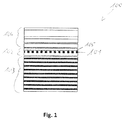
- Fig. 1 schematically illustrates a sectional view of lightning strike protection of an airframe component.
- reference sign 102 denotes a lightning strike protection layer placed on the top of a composite structure 100.
- the lightning strike protection layer 102 comprises e.g. an expanded copper foil 101 placed on the top of the composite laminate 103 but underneath protective dielectric coatings (e.g. paint layers) 104.
- a veil 105 (combined with an epoxy resin surfacing film) is placed on the top of ECF 101 in order to decrease the surface roughness and to prepare the surface for the final varnish that is for example made up of several layers, as shown in Fig. 1 .
- Fig. 2 shows a schematic sectional view of a structural component 1.
- the structural component 1 comprises a ply 2 of fiber reinforced polymer material, which comprises a matrix 8 and a plurality of carbon fibers 9.
- the structural component e. g. forms a carbon fiber reinforced polymer or carbon fiber reinforced plastic (CFRP) fuselage component of the skin 11 of an aircraft 10.
- CFRP carbon fiber reinforced plastic
- Fig. 2 schematically shows the arrangement of layers of the structural component at an outer side, which may form the outer skin of an aircraft at any section thereof.
- the hybrid LSP layer 5 comprises first and second non-woven carbon nano tube mats (CNT-M) 3, 6 and a metallic layer 4 configured as expanded copper foil (ECF).
- CNT-M non-woven carbon nano tube mats
- ECF expanded copper foil
- Carbon nanotubes generally are cylindrical shaped carbon forms with nanometric diameters. In particular, they have a hollow structure with walls made of graphite or of graphene (a hexagonal structure made of carbon atoms).
- Non-woven carbon nano tube mats can be manufactured e. g. by way of a gas-phase catalytic reaction creating a dense cloud of very long carbon nanotubes. These can be collected, for example spun around a drum, to create a non-woven mat.
- Such non-woven carbon nanotube mats are manufactured e.g. by Tortech Nano fibers Ltd., Israel or Nanocomp Technologies Inc., USA.
- An expanded copper foil may be made from a continuous expansion of copper, e. g. by rolling. It can be provided with different surface weights, depending on the number and thickness of CNT-M in the hybrid lightning strike protection layer 5.
- the first CNT-M 3 is arranged on the ply 2 of CFRP. Furthermore, a metallic layer 4 and a second carbon nanotube mat 6 are arranged on the first carbon nano tube mat 3. Accordingly, the metallic layer 4 is sandwiched between the first and second carbon nano tube mats 3, 6.
- the first and second carbon nano tube mats 3, 6 and the metallic layer 4 there between are completely embedded in the cured matrix 8 of the ply 2 of fiber reinforced polymer material. Therefore, the hybrid LSP layer is firmly bonded to the CFRP-ply 2 in an integrated way.
- the structural component 1 is covered with a dielectric coating 7, which is arranged directly on the outer side of the second carbon nano tube mat 6.
- Fig. 3 shows a sectional view of a prepreg component.
- the prepreg component is a component 1' for manufacturing a structural component 1 according to Fig. 2 by curing. Therefore, the prepreg component 1' comprises a ply 2' comprising a fiber material.
- the first carbon nano tube mat 3, the metallic layer 4 and the second carbon nano tube mat 6 are arranged on the ply in the order as described with reference to Fig. 2 . However, the dielectric layer is not yet applied.
- the ply 2', the first carbon nano tube mat 3, the metallic layer 4 and the second carbon nano tube mat 6 are impregnated with a non-cured matrix 8'.
- the first carbon nano tube mat 3 is placed on the ply 2'. Further, the metallic layer 4 is placed on the first carbon nano tube mat 3 and the second carbon nano tube mat 6 is placed on the metallic layer 4.
- the complete component is then impregnated with a non-cured matrix 8', which is e. g. a duroplastic/thermoset resin. This means, the ply 2', the first carbon nano tube mat 3, the metallic layer 4 and the second carbon nano tube mat 6 are all impregnated with the non-cured matrix 8' together to form the prepreg component 1'.
- a non-cured matrix 8' which is e. g. a duroplastic/thermoset resin.
- the matrix 8' of the prepreg component 1' is cured such that the ply comprising fiber material, the first carbon nano tube mat 3, the metallic component 4 and the second carbon nano tube mat are embedded in the cured matrix 8 and thus firmly bonded with each other.
- the outer side of the second carbon nano tube mat 6 is coated with a dielectric coating 7.
- Fig. 4 shows a front view of an exemplary aircraft 10.
- the aircraft 10 comprises a skin 11, part of which is formed as a structural component 1 according Fig. 2 .
- the aircraft (10) comprises a hybrid lightning strike protection (LSP) measure comprising an expanded copper foil (ECF) and a CNT non-woven mat (CNT-M).
- LSP hybrid lightning strike protection
- ECF expanded copper foil
- CNT-M CNT non-woven mat
- the hybrid lightning strike protection layer generally may also work with one CNT-M only, depending on the layout thereof. Accordingly, the CNT-M or even a plurality of CNT-M can be placed either underneath or on top of the metallic layer or ECF.
- the metallic layer does not necessarily have to consist of an ECF, but may have either alternative or additional other elements.
- the invention also covers other metals or alloys, e. g. nickel, aluminium, iron, brass, bronze or the like.
- the metallic layer may comprise a metal or metal alloy with high conductivity comprising precious metal, such as e. g. silver.
- an expanded foil e.g. an electrolytic foil, a grid (e. g. a wire grid or a stamped grid), or the like may be used.
- the method for manufacturing the component or the structural component does not necessarily have to comprise a step of impregnation of the ply comprising fiber material.
- the ply may also be provided as already cured ply, e. g. of CFRP or GFRP, and only the hybrid lightning strike protection layer, meaning at least the first CNT-M and the metallic layer, are firmly bonded thereto, e. g. by means of impregnation and curing.
Landscapes
- Chemical & Material Sciences (AREA)
- Engineering & Computer Science (AREA)
- Materials Engineering (AREA)
- Nanotechnology (AREA)
- Composite Materials (AREA)
- Health & Medical Sciences (AREA)
- Medicinal Chemistry (AREA)
- Polymers & Plastics (AREA)
- Organic Chemistry (AREA)
- Manufacturing & Machinery (AREA)
- Mechanical Engineering (AREA)
- Chemical Kinetics & Catalysis (AREA)
- Aviation & Aerospace Engineering (AREA)
- Textile Engineering (AREA)
- Physics & Mathematics (AREA)
- Condensed Matter Physics & Semiconductors (AREA)
- General Physics & Mathematics (AREA)
- Crystallography & Structural Chemistry (AREA)
- Inorganic Chemistry (AREA)
- Laminated Bodies (AREA)
- Reinforced Plastic Materials (AREA)
Abstract
Description
- The present invention pertains to a structural component, in particular for an aircraft, spacecraft or rocket. The invention further pertains to a component for manufacturing such a structural component, a method for manufacturing a component of this type, a method for manufacturing a structural component and an aircraft or spacecraft comprising such a structural component.
- Although applicable to any kind of structure that should be protected from lightning and/or electromagnetic pulse, the present invention and the problem on which it is based will be explained in greater detail with reference to the fuselage structure of an aircraft, spacecraft or rocket.
- In fiber reinforced polymer or fiber reinforced plastic structural parts, in particular carbon fiber reinforced plastic (CFRP) or glass fiber reinforced plastic (GFRP), additional lightning strike protection and electromagnetic shielding measures are usually provided.
- A solution known by the applicant for lightning strike protection (LSP) of composites (CFRP and GFRP) airframe structures is a lightning strike protection layer in the form of expanded metallic, in most cases copper foils (ECF), as shown in
Fig.1 . Such expanded metallic/copper foils 101 are generally placed on the top ofcomposite structures 100. This specific design of a lightningstrike protection layer 102 helps to dissipate the lightning strike energy over the surface, e. g. of anairframe component 100. Since the electrical resistivity of expanded copper foils is significantly larger than that of CFRP/GFRP laminate, the lightning current flows almost completely within the lightningstrike protection layer 102 not affecting directly the composite laminate 103 of thecomposite structure 100. - Other solutions for lightning strike protection measures known by the applicant are other metallic layers, such as woven wire fabrics, interwoven metallic wires, metal coatings, solid metal foils or conductive and ionisable paints.
- Another concept of lightning strike protection measure is described e. g. in
document DE 10 2007 057 491 A1 : A component useful in aircraft and spacecraft vehicles, comprises a resin matrix in which carbon nanotubes are embedded for high conductivity of the component, and an internal layer at which an external layer adjoins. A carbon fiber material is embedded in the resin matrix, which forms the external layer of the component. The internal layer is made of a fiber composite material. - Particularly in aerospace applications, the use of carbon nanotubes (CNT) due to their superior properties for multifunctional applications seems to be very promising. A review about the imminent prospects of utilizing carbon nanotubes due to their superior mechanical, thermal, and electrical properties for multifunctional aircraft and space applications can be found for example in Gohardani, O., et al., "Potential and prospective implementation of carbon nanotubes on next generation aircraft and space vehicles: A review of current and expected applications in aerospace sciences", Progress in Aerospace Sciences, 70, 42, 2014.
- The usually used Polyacrylnitril (PAN)-derived carbon fibres in CFRP laminates offer a sufficient high electrical and a reasonable thermal conductivity, but the epoxy matrix is from an electrical point of view an excellent electrical isolator. In case of GFRP structures, the glass fibres are electrically non-conducting. Thus, the general procedure for LSP purposes is to improve the matrix properties, particularly the electrical (and thermal) conductivity, and possibly to network the carbon fibres both within and between the adjacent plies, e.g. using carbon allotropes like carbon nanotubes (CNT). Also, other carbon allotropes like carbon black, short carbon fibres (SCF) or graphene plates may be used.
- It is one object of the present invention to provide for an improved structural component.
- This object is solved by a structural component, in particular for an aircraft, spacecraft or rocket, according to claim 1. Furthermore, the object is solved by a component for manufacturing such a structural component according to
claim 7 and/or a method for manufacturing a component according to claim 9 and/or a method for manufacturing a structural component according to claim 11. - Accordingly, the invention provides:
- A structural component, in particular for an aircraft, spacecraft or rocket, comprising: a ply of fiber reinforced polymer; a first carbon nano tube mat; and a metallic layer, wherein the carbon nano tube mat and the metallic layer are arranged on the ply of fiber reinforced polymer to form a hybrid lightning strike protection layer.
- A component for manufacturing a structural component according to the invention, comprising: a ply comprising fiber material; a metallic layer; and a first carbon nano tube mat, wherein the first carbon nano tube mat and the metallic layer are arranged on the ply.
- A method for manufacturing a component according to the invention, comprising: placing a metallic layer, in particular an expanded copper foil, and a first carbon nano tube mat on a ply comprising fiber material.
- A method for manufacturing a structural component, in particular a structural component according to the invention, comprising: curing the matrix of a component according to the invention or manufactured according to a method for manufacturing a component of the invention such that at least the first carbon nano tube mat and the metallic component are embedded in the cured matrix.
- An aircraft, spacecraft or rocket comprising a structural component according to the invention and/or manufactured according to a method of the invention.
- One idea of the present invention is to combine a metallic layer and a carbon nanotubes mat (CNT-M) to form a hybrid lightning strike protection (LSP) layer. The hybrid lightning strike protection (LSP) layer also serves as electromagnetic shielding measure.
- An LSP measure or LSP layer according to the invention advantageously has the same or even a lower weight than a standard LSP measure/layer. Moreover, mechanical damage of CFRP/GFRP laminates protected by the LSP measure according to the invention is significantly reduced.
- Since the CNT-M have high electrical conductivity, they contribute to enhanced electrical conductivity in the hybrid lightning strike protection layer. Thus, thermomechanical damage of CFRP/GFRP structure is reduced in case of a lightning strike, because the hybrid LSP layer comprising the metallic layer and the CNT-M has lower electrical resistance than e. g. a metal LSP layer. Therefore, the generated Joule heat is advantageously reduced.
- Additionally, the CNT-M have an outstanding thermal stability, since the melting temperature of CNTs is about 4000 °C and thus much higher than e. g. that of copper of about 1084 °C. Accordingly, the CNT-M may support the metallic layer at very high temperature such that the hybrid protection layer is more thermally-stable than ECF alone and additionally allows energy storage in the form of latent heat. Since the CNT-M reduce the magnitude of Joule heat generated by the light-ning strike currents and also have high thermal conductivity, they dissipate the generated heat faster from the lightning strike areas.
- The CNT-M advantageously are electro-chemical compatible with CFRP and GFRP materials. They can be easily incorporated with composite structures and are easily paintable. Thus, the CNT-M can replace the usual surfacing film layer and provides similar functionality integrated with the LSP properties. Accordingly, the LSP measure according to the present invention has the same or even lower weight than a standard LSP measure, in particular depending on the surface weight of the metallic layer used.
- Additionally, the surface weight of a metallic layer, for example an ECF, can be reduced with the hybrid design. Thus, the hybrid LSP measure/layer will have the same or even lower weight than standard LSP measures/layers, in particular compared to ECF only. However, still an improved electrical conductivity is provided with the hybrid LSP layer according to the invention.
- Finally, since CNT-M are extremely thermally stable, less energy is available for an explosion of the LSP layer. Thus, according to the present invention, mechanical damage of CFRP / GFRP composite structures from lightning is significantly reduced. Accordingly, lightning induced repair and maintenance cost are decreased.
- Advantageously, already available manufacturing processes can be used for the present invention. Thus, complexity and cost of manufacturing are not increased. Moreover, already available repair and maintenance processes for lightning strike induced damage can be used as well. Accordingly, additional complexity and cost of manufacturing, repair and maintenance of protected CFRP / GFRP structure are preserved.
- To sum up, the hybrid LSP layer according to the invention provides for a combination of desired properties and eliminates drawbacks of its single components in a synergetic way.
- Generally, the CNT-M can be placed either underneath or on the top of the metallic layer. Furthermore, it is possible to sandwich the metallic layer between two CNT-Ms.
- The metallic layer may comprise any industrial metal or metal alloy with sufficiently high conductivity, e. g. comprising copper, nickel, aluminium, brass, bronze, or the like. For special applications, the metallic layer may comprise a metal or metal alloy with high conductivity comprising precious metal, such as e. g. silver.
- The method of the present invention is variable regarding sequence of its steps. In particular, the step of impregnating may be conducted before or after the step of placement. Furthermore, infiltration or impregnation of the ply and the carbon nano tube mat may be conducted together in one step or separately. In particular, it is possible to use a readily cured ply of fiber reinforced polymer as ply comprising fiber material and firmly bond the carbon nano tube mat and metallic layer thereto by way of curing a matrix of the carbon nano tube mat.
- The method of manufacturing a structural component may involve all steps of the method of manufacturing a component for manufacturing a structural component.
- Manufacturing a structural component or a (non-cured or not completely cured) component for manufacturing the structural component may be realized by various molding processes, such as among others e. g. Pre-preg, Preforming, RTM (Resin Transfer Molding), Liquid Compression Molding, SMC (Sheet Moulding Compound), RIM (Reaction Injection Molding), BMC (Bulk Molding Compound), Extrusion Compression Molding, Structural Reaction Injection Molding, CFRTP (Carbon Fiber Reinforced ThermoPlastic) or the like.
- Accordingly, a component for manufacturing the structural component may be provided as a semi-finished product in various configurations suitable for the respective molding process, e. g. as a preform or as a prepreg.
- After curing, the metallic layer is embedded in the cured matrix on the CNT-M or between two CNT-Ms or between the CNT-M and the ply comprising fiber material.
- Advantageous embodiments and improvements of the present invention are found in the subordinate claims.
- According to an embodiment of the structural component, the first carbon nano tube mat and the metallic layer are embedded in a matrix. For example, the matrix is a cured polymer resin. In particular the matrix of the ply of fiber reinforced polymer is the matrix in which the first carbon nano tube mat and the metallic layer are embedded. In this case, accordingly, the matrix embeds at least the fibers of the fiber material, the metallic layer and the first carbon nano tube mat. In this way, an integrated design of the structural component with the LSP measure/layer is provided.
- According to a further embodiment of the structural component or according to an embodiment of the component for manufacturing the structural component, the hybrid lightning strike protection layer comprises a second carbon nano tube mat. In this case, the metallic layer is arranged between the first carbon nano tube mat and the second carbon nano tube mat. Accordingly, the metallic layer is sandwiched between the first and second CNT-M. In this way, improved thermal stability is achieved, since the CNT-Ms structurally support the metallic layer from both sides under very high temperature conditions.
- According to a further embodiment of the structural component, the first carbon nano tube mat is arranged on the ply of fiber reinforced polymer. Accordingly, the first carbon nano tube mat is arranged on the ply comprising fiber material in an embodiment of a component for manufacturing the structural component. Thus, the metallic layer is arranged on the first carbon nano tube mat. In case a second carbon nano tube mat is provided, the metallic layer is preferably arranged between the first and second carbon nano tube mats. Alternatively or in addition, a dielectric coating or paint can be arranged on the second carbon nano tube mat. In this way, the CNT-M can replace conventional surfacing film layers and thus offers the same functionality as the surfacing film layer plus its LSP function in an integral way. Furthermore, a conventional veil can be omitted. Therefore, the hybrid LSP layer advantageously has low weight, in particular lower weight compared to conventional LSP measures.
- According to an embodiment of the component for manufacturing the structural component, at least the first carbon nano tube mat is impregnated with a non-cured matrix. For example, the component is configured as prepreg component. Other parts of the component may also be impregnated. In an embodiment, also the ply comprising fiber material and/or a second carbon nano tube mat is impregnated with the non-cured matrix. In this way, a pre-product or semi-finished product, in particular a prepreg or preform, is provided which, in particular independently, allows finishing the manufacturing of a structural component by curing.
- According to a further embodiment of the structural component or according to an embodiment of the component for manufacturing the structural component, the metallic layer comprises copper. In this way, the properties of the CNT-M are ideally added with the high conductivity of copper to advantageously provide for minimum effective electrical resistance. Optionally or in addition, the metallic layer is configured as an expanded metallic foil. In this way, a low surface weight and high extensive expansion of the metallic layer is provided. In a preferred embodiment, the metallic layer comprises or is configured as an expanded copper foil.
- According to a further embodiment of the structural component or according to an embodiment of the component for manufacturing the structural component, the first carbon nano tube mat is configured as non-woven carbon nano tube mat. Additionally, also the second carbon nanotube mat may be configured as non-woven carbon nano tube mat. Non-woven carbon nano tube mats provide for a large size, are easy to handle and flexible. Furthermore, the CNTs don't need to be dispersed. In particular, the CNT-M is made of 100% CNTs, meaning pure CNT fabric. Thus it easily and cost-effectively can be impregnated with a resin using custom industrial techniques. Since the non-woven CNTs in the mat have a high aspect ratio (∼1:100,000), improved electrical, thermal and mechanical properties are provided.
- According to an embodiment of the method for manufacturing a component, the method further comprises a step of impregnating at least the first carbon nano tube mat with a non-cured matrix. In this way, the component can be manufactured as a prepreg component. Other parts of the component may also be impregnated simultaneously or in sequence. In an embodiment, also the ply comprising fiber material and/or a second carbon nano tube mat is impregnated with the non-cured matrix. In this way, a pre-product or semi-finished product, in particular a prepreg, is manufactured which, in particular independently, allows finishing the manufacturing of a structural component by curing.
- According to an embodiment of the method for manufacturing a component or according to an embodiment of the method for manufacturing a structural component, the first carbon nano tube mat, the metallic layer and the ply are impregnated with the matrix together. In this way, an integrated manufacturing process, in particular with only one impregnation step, is provided.
- Furthermore, according to an embodiment of the method for manufacturing a structural component, the first carbon nano tube mat, the metallic layer and the ply are embedded together in the cured matrix. In this way, an LSP layer for a structural component can be manufactured in an integrated and labor-saving process with conventional tooling. Accordingly, manufacture is possible with low complexity and thus at low cost.
- According to an embodiment of manufacturing the component or according to an embodiment of the method for manufacturing a structural component, placing the metallic layer and the first carbon nano tube mat on the ply comprises the steps of placing the first carbon nano tube mat on the ply; placing the metallic layer on the first carbon nano tube mat; and placing a second carbon nano tube mat on the metallic layer. In this way, an LSP-layer with double CNT-M enclosing the metallic layer, preferably an ECF, is provided. In this way, the hybrid LSP layer is provided with improved thermal stability.
- According to yet another embodiment of the method of manufacturing the pre-preg component or according to an embodiment of the method for manufacturing a structural component, the method further comprises the step of coating the second carbon nano tube mat with a dielectric coating or paint. In particular, the coating or paint is applied directly on the second carbon nano tube mat. In this way, advantageously, a conventional surfacing film and/or a conventional veil can be omitted. The dielectric coating or paint may be applied before or after curing of the matrix.
- According to an embodiment of an aircraft or spacecraft, the structural component forms part of a skin of the aircraft or spacecraft. In this way, advantageously, an effective lightning strike protection (LSP) measure is provided in the aircraft or spacecraft.
- The above embodiments may be combined in any reasonable way. In particular, features of the prepreg component are applicable to the structural component and vice versa. Furthermore, features of the method for manufacturing a prepreg component are applicable to the method for manufacturing the structural component and vice versa.
- The invention will be explained in greater detail with reference to exemplary embodiments depicted in the drawings as appended.
- The accompanying drawings are included to provide a further understanding of the present invention and are incorporated in and constitute a part of this specification. The drawings illustrate the embodiments of the present invention and together with the description serve to explain the principles of the invention. Other embodiments of the present invention and many of the intended advantages of the present invention will be readily appreciated as they become better understood by reference to the following detailed description. The elements of the drawings are not necessarily to scale relative to each other. In the figures, like reference numerals denote like or functionally like components, unless indicated otherwise.
- It will be appreciated that common and/or well understood elements that may be useful or necessary in a commercially feasible embodiment are not necessarily depicted in order to facilitate a more abstracted view of the embodiments. It will further be appreciated that certain actions and/or steps in an embodiment of a method may be described or depicted in a particular order of occurrences while those skilled in the art will understand that such specificity with respect to sequence is not actually required. It will also be understood that the terms and expressions used in the present specification have the ordinary meaning as is accorded to such terms and expressions with respect to their corresponding respective areas of inquiry and study, except where specific meanings have otherwise been set forth herein.
- Fig. 1
- schematically illustrates an exemplary sectional view of lightning strike protection measures of an airframe component.
- Fig. 2
- shows a schematic sectional view of a structural component.
- Fig. 3
- shows a schematic sectional view of a prepreg component.
- Fig. 4
- shows a front view of an exemplary aircraft.
- Although specific embodiments are illustrated and described herein, it will be appreciated by those of ordinary skill in the art that a variety of alternate and/or equivalent implementations may be substituted for the specific embodiments shown and described without departing from the scope of the present invention. Generally, this application is intended to cover any adaptations or variations of the specific embodiments discussed herein.
-
Fig. 1 schematically illustrates a sectional view of lightning strike protection of an airframe component. - In
Fig. 1 ,reference sign 102 denotes a lightning strike protection layer placed on the top of acomposite structure 100. The lightningstrike protection layer 102 comprises e.g. an expandedcopper foil 101 placed on the top of the composite laminate 103 but underneath protective dielectric coatings (e.g. paint layers) 104. - A veil 105 (combined with an epoxy resin surfacing film) is placed on the top of
ECF 101 in order to decrease the surface roughness and to prepare the surface for the final varnish that is for example made up of several layers, as shown inFig. 1 . -
Fig. 2 shows a schematic sectional view of a structural component 1. - The structural component 1 comprises a ply 2 of fiber reinforced polymer material, which comprises a
matrix 8 and a plurality of carbon fibers 9. The structural component e. g. forms a carbon fiber reinforced polymer or carbon fiber reinforced plastic (CFRP) fuselage component of the skin 11 of anaircraft 10. The ply 2 of fiber reinforced polymer material thereby forms the structural basis of the structural component 1. - It is to be understood that
Fig. 2 schematically shows the arrangement of layers of the structural component at an outer side, which may form the outer skin of an aircraft at any section thereof. - On the outer side of the ply 2 of fiber reinforced polymer, a hybrid lightning strike protection (LSP)
layer 5 is arranged. Thehybrid LSP layer 5 comprises first and second non-woven carbon nano tube mats (CNT-M) 3, 6 and a metallic layer 4 configured as expanded copper foil (ECF). - Carbon nanotubes (CNT) generally are cylindrical shaped carbon forms with nanometric diameters. In particular, they have a hollow structure with walls made of graphite or of graphene (a hexagonal structure made of carbon atoms). Non-woven carbon nano tube mats (CNT-M) can be manufactured e. g. by way of a gas-phase catalytic reaction creating a dense cloud of very long carbon nanotubes. These can be collected, for example spun around a drum, to create a non-woven mat. Such non-woven carbon nanotube mats are manufactured e.g. by Tortech Nano fibers Ltd., Israel or Nanocomp Technologies Inc., USA.
- An expanded copper foil (ECF) may be made from a continuous expansion of copper, e. g. by rolling. It can be provided with different surface weights, depending on the number and thickness of CNT-M in the hybrid lightning
strike protection layer 5. - In the embodiment of
fig. 2 , the first CNT-M 3 is arranged on the ply 2 of CFRP. Furthermore, a metallic layer 4 and a second carbon nanotube mat 6 are arranged on the first carbon nano tube mat 3. Accordingly, the metallic layer 4 is sandwiched between the first and second carbon nano tube mats 3, 6. - The first and second carbon nano tube mats 3, 6 and the metallic layer 4 there between are completely embedded in the cured
matrix 8 of the ply 2 of fiber reinforced polymer material. Therefore, the hybrid LSP layer is firmly bonded to the CFRP-ply 2 in an integrated way. - Additionally, the structural component 1 is covered with a
dielectric coating 7, which is arranged directly on the outer side of the second carbon nano tube mat 6. -
Fig. 3 shows a sectional view of a prepreg component. - The prepreg component is a component 1' for manufacturing a structural component 1 according to
Fig. 2 by curing. Therefore, the prepreg component 1' comprises a ply 2' comprising a fiber material. The first carbon nano tube mat 3, the metallic layer 4 and the second carbon nano tube mat 6 are arranged on the ply in the order as described with reference toFig. 2 . However, the dielectric layer is not yet applied. - The ply 2', the first carbon nano tube mat 3, the metallic layer 4 and the second carbon nano tube mat 6 are impregnated with a non-cured matrix 8'.
- For manufacturing the prepreg component, the first carbon nano tube mat 3 is placed on the ply 2'. Further, the metallic layer 4 is placed on the first carbon nano tube mat 3 and the second carbon nano tube mat 6 is placed on the metallic layer 4. The complete component is then impregnated with a non-cured matrix 8', which is e. g. a duroplastic/thermoset resin. This means, the ply 2', the first carbon nano tube mat 3, the metallic layer 4 and the second carbon nano tube mat 6 are all impregnated with the non-cured matrix 8' together to form the prepreg component 1'.
- For manufacturing a structural component 1 according to
Fig. 2 , the matrix 8' of the prepreg component 1' is cured such that the ply comprising fiber material, the first carbon nano tube mat 3, the metallic component 4 and the second carbon nano tube mat are embedded in the curedmatrix 8 and thus firmly bonded with each other. - Finally, the outer side of the second carbon nano tube mat 6 is coated with a
dielectric coating 7. -
Fig. 4 shows a front view of anexemplary aircraft 10. Theaircraft 10 comprises a skin 11, part of which is formed as a structural component 1 accordingFig. 2 . - Accordingly, the aircraft (10) comprises a hybrid lightning strike protection (LSP) measure comprising an expanded copper foil (ECF) and a CNT non-woven mat (CNT-M).
- Although specific embodiments of the invention are illustrated and described herein, it will be appreciated by those of ordinary skill in the art that a variety of alternate and/or equivalent implementations exist. It should be appreciated that the exemplary embodiment or exemplary embodiments are examples only and are not intended to limit the scope, applicability, or configuration in any way. Rather, the foregoing summary and detailed description will provide those skilled in the art with a convenient road map for implementing at least one exemplary embodiment, it being understood that various changes may be made in the function and arrangement of elements described in an exemplary embodiment without departing from the scope as set forth in the appended claims and their legal equivalents. Generally, this application is intended to cover any adaptations or variations of the specific embodiments discussed herein.
- For example, it is not ultimately necessary to provide a second CNT non-woven mat. The hybrid lightning strike protection layer generally may also work with one CNT-M only, depending on the layout thereof. Accordingly, the CNT-M or even a plurality of CNT-M can be placed either underneath or on top of the metallic layer or ECF.
- Additionally, the metallic layer does not necessarily have to consist of an ECF, but may have either alternative or additional other elements. In particular, the invention also covers other metals or alloys, e. g. nickel, aluminium, iron, brass, bronze or the like. For special applications, the metallic layer may comprise a metal or metal alloy with high conductivity comprising precious metal, such as e. g. silver. Furthermore, other kinds of layers then an expanded foil, e.g. an electrolytic foil, a grid (e. g. a wire grid or a stamped grid), or the like may be used.
- Furthermore, the method for manufacturing the component or the structural component does not necessarily have to comprise a step of impregnation of the ply comprising fiber material. The ply may also be provided as already cured ply, e. g. of CFRP or GFRP, and only the hybrid lightning strike protection layer, meaning at least the first CNT-M and the metallic layer, are firmly bonded thereto, e. g. by means of impregnation and curing.
- It will also be appreciated that in this document the terms "comprise", "comprising", "include", "including", "contain", "containing", "have", "having", and any variations thereof, are intended to be understood in an inclusive (i.e. non-exclusive) sense, such that the process, method, device, apparatus or system described herein is not limited to those features or parts or elements or steps recited but may include other elements, features, parts or steps not expressly listed or inherent to such process, method, article, or apparatus. Furthermore, the terms "a" and "an" used herein are intended to be understood as meaning one or more unless explicitly stated otherwise. Moreover, the terms "first", "second", "third", etc. are used merely as labels, and are not intended to impose numerical requirements on or to establish a certain ranking of importance of their objects.
-
- 1
- structural component
- 1'
- component
- 2
- ply of fiber reinforced polymer
- 2'
- ply comprising fiber material
- 3
- first carbon nano tube mat
- 4
- metallic layer
- 5
- hybrid lightning strike protection layer
- 6
- second carbon nano tube mat
- 7
- dielectric coating
- 8
- matrix
- 8'
- non-cured matrix
- 9
- fibers
- 10
- aircraft
- 11
- skin
- 100
- airframe component
- 101
- expanded copper foil
- 102
- lightning strike protection layer
- 103
- composite laminate
- 104
- dielectric coatings
- 105
- veil
Claims (15)
- Structural component (1), in particular for an aircraft, spacecraft or rocket (10), comprising:a ply (2) of fiber reinforced polymer;a first carbon nano tube mat (3); anda metallic layer (4), wherein the carbon nano tube mat (3) and the metallic layer (4) are arranged on the ply (2) of fiber reinforced polymer to form a hybrid lightning strike protection layer (5).
- Component (1) according to claim 1,
wherein the first carbon nano tube mat (3) and the metallic layer (4) are embedded in a matrix, in particular in the matrix of the ply (2) of fiber reinforced polymer. - Component (1) according to any one of the preceding claims,
wherein the hybrid lightning strike protection layer (5) comprises a second carbon nano tube mat (6), wherein the metallic layer (4) is arranged between the first carbon nano tube mat (3) and the second carbon nano tube mat (6). - Component (1) according to claim 3,
wherein the first carbon nano tube mat (3) is arranged on the ply (2) of fiber reinforced polymer and/or wherein a dielectric coating or paint (7) is applied on the second carbon nano tube mat (6). - Component (1; 1') according to any one of the preceding claims,
wherein the metallic layer (4) comprises copper and/or is configured as an expanded metallic foil, in particular an expanded copper foil. - Component (1; 1') according to any one of the preceding claims,
wherein the first carbon nano tube mat (3) is configured as non-woven carbon nano tube mat. - Component (1') for manufacturing a structural component (1) according to one of the preceding claims, comprising:a ply (2') comprising fiber material;a metallic layer (4);a first carbon nano tube mat (3), wherein the first carbon nano tube mat (3) and the metallic layer (4) are arranged on the ply (2').
- Component (1') according to claim 7,
wherein at least the first carbon nano tube mat (3) is impregnated with a non-cured matrix (8'). - Method for manufacturing a component according to one of claims 7 or 8, comprising:placing a metallic layer (4), in particular an expanded copper foil, and a first carbon nano tube mat (3) on a ply (2') comprising fiber material.
- Method according to claim 9, further comprising a step of impregnating at least the first carbon nano tube mat (3) with a non-cured matrix (8').
- Method for manufacturing a structural component, in particular a structural component (1) according to any one of claims 1 to 6, comprising:curing the matrix (8') of a component (1') according to claim 8 or manufactured according to a method of claim 10 such that at least the first carbon nano tube mat (3) and the metallic component (4) are embedded in the cured matrix (8).
- Method according to claim 11, wherein the first carbon nano tube mat (3), the metallic layer (4) and the ply (2; 2') are impregnated with the matrix (8') together and/or embedded together in the cured matrix (8).
- Method according to any one of claims 9 to 12, wherein placing the metallic layer (4) and the first carbon nano tube mat (3) on the ply (2') comprises:placing the first carbon nano tube mat (3) on the ply (2; 2');placing the metallic layer (4) on the first carbon nano tube mat (3); andplacing a second carbon nano tube mat (6) on the metallic layer (4).
- Method according to claim 13, further comprising the step of coating the second carbon nano tube mat (6) with a dielectric coating or paint (7).
- Aircraft, spacecraft or rocket (10) comprising a structural component (1) according to any one of claims 1 to 6 and/or manufactured according to a method of any one of claims 11 to 14.
Priority Applications (4)
| Application Number | Priority Date | Filing Date | Title |
|---|---|---|---|
| EP19178923.9A EP3564184B1 (en) | 2016-04-08 | 2016-04-08 | Structural fibre-reinforced component with lightning strike protection by using carbon nano tube mats and metallic layers |
| EP16164424.0A EP3228585B1 (en) | 2016-04-08 | 2016-04-08 | Structural fibre-reinforced component with lightning strike protection by using carbon nano tube mats and metallic layers |
| US15/471,795 US11161320B2 (en) | 2016-04-08 | 2017-03-28 | Structural component |
| US17/494,913 US11969983B2 (en) | 2016-04-08 | 2021-10-06 | Structural component |
Applications Claiming Priority (1)
| Application Number | Priority Date | Filing Date | Title |
|---|---|---|---|
| EP16164424.0A EP3228585B1 (en) | 2016-04-08 | 2016-04-08 | Structural fibre-reinforced component with lightning strike protection by using carbon nano tube mats and metallic layers |
Related Child Applications (2)
| Application Number | Title | Priority Date | Filing Date |
|---|---|---|---|
| EP19178923.9A Division-Into EP3564184B1 (en) | 2016-04-08 | 2016-04-08 | Structural fibre-reinforced component with lightning strike protection by using carbon nano tube mats and metallic layers |
| EP19178923.9A Division EP3564184B1 (en) | 2016-04-08 | 2016-04-08 | Structural fibre-reinforced component with lightning strike protection by using carbon nano tube mats and metallic layers |
Publications (2)
| Publication Number | Publication Date |
|---|---|
| EP3228585A1 true EP3228585A1 (en) | 2017-10-11 |
| EP3228585B1 EP3228585B1 (en) | 2019-08-07 |
Family
ID=55745593
Family Applications (2)
| Application Number | Title | Priority Date | Filing Date |
|---|---|---|---|
| EP16164424.0A Active EP3228585B1 (en) | 2016-04-08 | 2016-04-08 | Structural fibre-reinforced component with lightning strike protection by using carbon nano tube mats and metallic layers |
| EP19178923.9A Active EP3564184B1 (en) | 2016-04-08 | 2016-04-08 | Structural fibre-reinforced component with lightning strike protection by using carbon nano tube mats and metallic layers |
Family Applications After (1)
| Application Number | Title | Priority Date | Filing Date |
|---|---|---|---|
| EP19178923.9A Active EP3564184B1 (en) | 2016-04-08 | 2016-04-08 | Structural fibre-reinforced component with lightning strike protection by using carbon nano tube mats and metallic layers |
Country Status (2)
| Country | Link |
|---|---|
| US (2) | US11161320B2 (en) |
| EP (2) | EP3228585B1 (en) |
Cited By (4)
| Publication number | Priority date | Publication date | Assignee | Title |
|---|---|---|---|---|
| EP3492251A1 (en) * | 2017-11-30 | 2019-06-05 | Airbus Operations GmbH | Method for producing a composite component |
| CN111070722A (en) * | 2018-10-19 | 2020-04-28 | 哈尔滨工业大学 | A kind of preparation method of lightning protection composite material based on heat insulation and insulation mechanism |
| LU102368B1 (en) * | 2020-12-31 | 2022-06-30 | Luxembourg Inst Science & Tech List | Lightning strike protection material and Structure |
| EP4681914A1 (en) * | 2024-07-17 | 2026-01-21 | The Boeing Company | Modified modulus composite laminate system and method of using the same |
Families Citing this family (7)
| Publication number | Priority date | Publication date | Assignee | Title |
|---|---|---|---|---|
| EP3228585B1 (en) | 2016-04-08 | 2019-08-07 | Airbus Defence and Space GmbH | Structural fibre-reinforced component with lightning strike protection by using carbon nano tube mats and metallic layers |
| WO2020160309A1 (en) * | 2019-01-30 | 2020-08-06 | Dirtt Environmental Solutions, Ltd. | Magnesium-oxide wall tiles for modular wall systems |
| CN113661056B (en) * | 2019-03-29 | 2025-03-04 | 塞特工业公司 | Permeable material with lightning strike protection and its use in resin infusion processes |
| GB2609421B (en) | 2021-07-29 | 2026-03-25 | Airbus Operations Ltd | Laminate structure |
| GB2614720A (en) | 2022-01-13 | 2023-07-19 | Airbus Operations Ltd | Lightning strike protection layer |
| JP2025002103A (en) * | 2023-06-21 | 2025-01-09 | 三菱重工業株式会社 | Thunder resistant structure of rocket, rocket including the same and method for manufacturing thunder resistant structure of rocket |
| EP4721974A1 (en) * | 2024-10-02 | 2026-04-08 | Airbus (S.A.S.) | Method for bonding a conductive layer to a substrate |
Citations (3)
| Publication number | Priority date | Publication date | Assignee | Title |
|---|---|---|---|---|
| DE102007057491A1 (en) | 2007-11-29 | 2009-06-04 | Airbus Deutschland Gmbh | Component useful in air- and space-craft vehicles, has resin matrix in which carbon nanotubes are embedded for high conductivity of component, and internal layer, at which external layer adjoins and which is made of fiber composite material |
| US8800911B2 (en) * | 2009-08-28 | 2014-08-12 | Rohr, Inc. | Lightning strike protection |
| US20160031569A1 (en) * | 2014-08-01 | 2016-02-04 | Airbus Defence and Space GmbH | Lightning Protection Layer for Fiber Composite Structures |
Family Cites Families (6)
| Publication number | Priority date | Publication date | Assignee | Title |
|---|---|---|---|---|
| US8962130B2 (en) * | 2006-03-10 | 2015-02-24 | Rohr, Inc. | Low density lightning strike protection for use in airplanes |
| US7628879B2 (en) * | 2007-08-23 | 2009-12-08 | The Boeing Company | Conductive scrim embedded structural adhesive films |
| JP5055178B2 (en) * | 2008-03-24 | 2012-10-24 | 三菱重工業株式会社 | Aircraft assembly |
| US9254606B2 (en) * | 2009-01-20 | 2016-02-09 | Florida State University Research Foundation | Nanoscale fiber films, composites, and methods for alignment of nanoscale fibers by mechanical stretching |
| US9511562B2 (en) * | 2012-07-03 | 2016-12-06 | Rohr, Inc. | Nanoreinforced films and laminates for aerospace structures |
| EP3228585B1 (en) | 2016-04-08 | 2019-08-07 | Airbus Defence and Space GmbH | Structural fibre-reinforced component with lightning strike protection by using carbon nano tube mats and metallic layers |
-
2016
- 2016-04-08 EP EP16164424.0A patent/EP3228585B1/en active Active
- 2016-04-08 EP EP19178923.9A patent/EP3564184B1/en active Active
-
2017
- 2017-03-28 US US15/471,795 patent/US11161320B2/en active Active
-
2021
- 2021-10-06 US US17/494,913 patent/US11969983B2/en active Active
Patent Citations (3)
| Publication number | Priority date | Publication date | Assignee | Title |
|---|---|---|---|---|
| DE102007057491A1 (en) | 2007-11-29 | 2009-06-04 | Airbus Deutschland Gmbh | Component useful in air- and space-craft vehicles, has resin matrix in which carbon nanotubes are embedded for high conductivity of component, and internal layer, at which external layer adjoins and which is made of fiber composite material |
| US8800911B2 (en) * | 2009-08-28 | 2014-08-12 | Rohr, Inc. | Lightning strike protection |
| US20160031569A1 (en) * | 2014-08-01 | 2016-02-04 | Airbus Defence and Space GmbH | Lightning Protection Layer for Fiber Composite Structures |
Non-Patent Citations (1)
| Title |
|---|
| GOHARDANI, 0. ET AL.: "Potential and prospective implementation of carbon nanotubes on next generation aircraft and space vehicles: A review of current and expected applications in aerospace sciences", PROGRESS IN AEROSPACE SCIENCES, vol. 70, 2014, pages 42 |
Cited By (9)
| Publication number | Priority date | Publication date | Assignee | Title |
|---|---|---|---|---|
| EP3492251A1 (en) * | 2017-11-30 | 2019-06-05 | Airbus Operations GmbH | Method for producing a composite component |
| JP2019098743A (en) * | 2017-11-30 | 2019-06-24 | エアバス オペレーションズ ゲーエムベーハーAirbus Operations GmbH | Method of manufacturing composite component |
| US11548247B2 (en) | 2017-11-30 | 2023-01-10 | Airbus Operations Gmbh | Method for producing a composite component |
| CN111070722A (en) * | 2018-10-19 | 2020-04-28 | 哈尔滨工业大学 | A kind of preparation method of lightning protection composite material based on heat insulation and insulation mechanism |
| CN111070722B (en) * | 2018-10-19 | 2021-10-22 | 哈尔滨工业大学 | A kind of preparation method of lightning protection composite material based on heat insulation and insulation mechanism |
| LU102368B1 (en) * | 2020-12-31 | 2022-06-30 | Luxembourg Inst Science & Tech List | Lightning strike protection material and Structure |
| WO2022144325A1 (en) * | 2020-12-31 | 2022-07-07 | Luxembourg Institute Of Science And Technology (List) | Lightning strike protection material and structure |
| CN116669949A (en) * | 2020-12-31 | 2023-08-29 | 卢森堡科学技术研究院 | Lightning protection materials and structures |
| EP4681914A1 (en) * | 2024-07-17 | 2026-01-21 | The Boeing Company | Modified modulus composite laminate system and method of using the same |
Also Published As
| Publication number | Publication date |
|---|---|
| US11161320B2 (en) | 2021-11-02 |
| US11969983B2 (en) | 2024-04-30 |
| EP3228585B1 (en) | 2019-08-07 |
| US20220024174A1 (en) | 2022-01-27 |
| US20170291386A1 (en) | 2017-10-12 |
| EP3564184A1 (en) | 2019-11-06 |
| EP3564184B1 (en) | 2023-03-01 |
Similar Documents
| Publication | Publication Date | Title |
|---|---|---|
| US11969983B2 (en) | Structural component | |
| Gagné et al. | Lightning strike protection of composites | |
| Kumar et al. | Factors affecting direct lightning strike damage to fiber reinforced composites: A review | |
| EP3222514B1 (en) | Skin panel with an energy-storing layer for an aircraft or spacecraft and method for manufacturing an energy-storing layer for a skin panel | |
| EP2826809B1 (en) | Improved lightning strike protection | |
| CN108368614B (en) | Carbon nanomaterial composite sheet and method for making the same | |
| US8146861B2 (en) | Component with carbon nanotubes | |
| EP2419326B1 (en) | Lightning protection sheet with patterned discriminator | |
| US20140197273A1 (en) | Method for Producing a Surface Structure with Lightning Protection, and Surface Structure Which Can be Produced in This Way | |
| US20180176989A1 (en) | Heated floor panels with thermally conductive and electrically insulating fabric | |
| US9809324B2 (en) | Lightning protection layer for fiber composite structures | |
| Gao et al. | Stackable and Deployable Laser‐Induced Graphene Layers Toward the Flexible Manufacturing of Smart 3D Honeycombs with Multifunctional Performance | |
| EP3339178B1 (en) | Electrically conductive resin matrix for cnt heater | |
| CN102855965A (en) | Electrically conductive structure | |
| CN110498048A (en) | Structure member for aircraft | |
| Alemour et al. | Improving the electrical conductivity of carbon fiber reinforced epoxy composite using reduced graphene oxide | |
| WO2014156369A1 (en) | Fuel tank, main wings, aircraft fuselage, aircraft, and moving body | |
| Alarifi et al. | Mitigation of lightning strikes on composite aircraft via micro and nanoscale materials | |
| US11801666B2 (en) | Structure formed from composite material | |
| DE102012217543A1 (en) | Composite with fiber reinforcement, use of it and electric motor | |
| KR101564612B1 (en) | Multiscale composites for n-type element of thermoelectric device and manufacturing method of the same | |
| Shiverskii et al. | Electrical Heaters for Anti/De-Icing of Polymer Structures. Polymers 2023, 15, 1573 | |
| US20140110158A1 (en) | Carbon fiber spacecraft panel with integral metallic foil power return | |
| KR20230129180A (en) | Lightning protection materials and lightning protection structures | |
| Turner | Exploring the Use of Carbon Nanotubes in Aerospace Structural Components |
Legal Events
| Date | Code | Title | Description |
|---|---|---|---|
| PUAI | Public reference made under article 153(3) epc to a published international application that has entered the european phase |
Free format text: ORIGINAL CODE: 0009012 |
|
| STAA | Information on the status of an ep patent application or granted ep patent |
Free format text: STATUS: THE APPLICATION HAS BEEN PUBLISHED |
|
| AK | Designated contracting states |
Kind code of ref document: A1 Designated state(s): AL AT BE BG CH CY CZ DE DK EE ES FI FR GB GR HR HU IE IS IT LI LT LU LV MC MK MT NL NO PL PT RO RS SE SI SK SM TR |
|
| AX | Request for extension of the european patent |
Extension state: BA ME |
|
| STAA | Information on the status of an ep patent application or granted ep patent |
Free format text: STATUS: REQUEST FOR EXAMINATION WAS MADE |
|
| 17P | Request for examination filed |
Effective date: 20180406 |
|
| RBV | Designated contracting states (corrected) |
Designated state(s): AL AT BE BG CH CY CZ DE DK EE ES FI FR GB GR HR HU IE IS IT LI LT LU LV MC MK MT NL NO PL PT RO RS SE SI SK SM TR |
|
| STAA | Information on the status of an ep patent application or granted ep patent |
Free format text: STATUS: EXAMINATION IS IN PROGRESS |
|
| RIC1 | Information provided on ipc code assigned before grant |
Ipc: B29C 70/88 20060101ALI20181031BHEP Ipc: B29C 70/02 20060101ALI20181031BHEP Ipc: C08J 5/00 20060101ALN20181031BHEP Ipc: B82Y 30/00 20110101AFI20181031BHEP Ipc: B64D 45/02 20060101ALI20181031BHEP |
|
| 17Q | First examination report despatched |
Effective date: 20181119 |
|
| RIC1 | Information provided on ipc code assigned before grant |
Ipc: B29C 70/02 20060101ALI20190214BHEP Ipc: B82Y 30/00 20110101AFI20190214BHEP Ipc: B29C 70/88 20060101ALI20190214BHEP Ipc: B64D 45/02 20060101ALI20190214BHEP Ipc: C08J 5/00 20060101ALN20190214BHEP |
|
| GRAP | Despatch of communication of intention to grant a patent |
Free format text: ORIGINAL CODE: EPIDOSNIGR1 |
|
| STAA | Information on the status of an ep patent application or granted ep patent |
Free format text: STATUS: GRANT OF PATENT IS INTENDED |
|
| RIC1 | Information provided on ipc code assigned before grant |
Ipc: C08J 5/00 20060101ALN20190308BHEP Ipc: B64D 45/02 20060101ALI20190308BHEP Ipc: B29C 70/88 20060101ALI20190308BHEP Ipc: B82Y 30/00 20110101AFI20190308BHEP Ipc: B29C 70/02 20060101ALI20190308BHEP |
|
| INTG | Intention to grant announced |
Effective date: 20190403 |
|
| GRAS | Grant fee paid |
Free format text: ORIGINAL CODE: EPIDOSNIGR3 |
|
| GRAA | (expected) grant |
Free format text: ORIGINAL CODE: 0009210 |
|
| STAA | Information on the status of an ep patent application or granted ep patent |
Free format text: STATUS: THE PATENT HAS BEEN GRANTED |
|
| AK | Designated contracting states |
Kind code of ref document: B1 Designated state(s): AL AT BE BG CH CY CZ DE DK EE ES FI FR GB GR HR HU IE IS IT LI LT LU LV MC MK MT NL NO PL PT RO RS SE SI SK SM TR |
|
| REG | Reference to a national code |
Ref country code: GB Ref legal event code: FG4D |
|
| REG | Reference to a national code |
Ref country code: CH Ref legal event code: EP Ref country code: AT Ref legal event code: REF Ref document number: 1163569 Country of ref document: AT Kind code of ref document: T Effective date: 20190815 |
|
| REG | Reference to a national code |
Ref country code: DE Ref legal event code: R096 Ref document number: 602016017951 Country of ref document: DE |
|
| REG | Reference to a national code |
Ref country code: IE Ref legal event code: FG4D |
|
| REG | Reference to a national code |
Ref country code: NL Ref legal event code: MP Effective date: 20190807 |
|
| REG | Reference to a national code |
Ref country code: LT Ref legal event code: MG4D |
|
| PG25 | Lapsed in a contracting state [announced via postgrant information from national office to epo] |
Ref country code: PT Free format text: LAPSE BECAUSE OF FAILURE TO SUBMIT A TRANSLATION OF THE DESCRIPTION OR TO PAY THE FEE WITHIN THE PRESCRIBED TIME-LIMIT Effective date: 20191209 Ref country code: NO Free format text: LAPSE BECAUSE OF FAILURE TO SUBMIT A TRANSLATION OF THE DESCRIPTION OR TO PAY THE FEE WITHIN THE PRESCRIBED TIME-LIMIT Effective date: 20191107 Ref country code: SE Free format text: LAPSE BECAUSE OF FAILURE TO SUBMIT A TRANSLATION OF THE DESCRIPTION OR TO PAY THE FEE WITHIN THE PRESCRIBED TIME-LIMIT Effective date: 20190807 Ref country code: FI Free format text: LAPSE BECAUSE OF FAILURE TO SUBMIT A TRANSLATION OF THE DESCRIPTION OR TO PAY THE FEE WITHIN THE PRESCRIBED TIME-LIMIT Effective date: 20190807 Ref country code: LT Free format text: LAPSE BECAUSE OF FAILURE TO SUBMIT A TRANSLATION OF THE DESCRIPTION OR TO PAY THE FEE WITHIN THE PRESCRIBED TIME-LIMIT Effective date: 20190807 Ref country code: HR Free format text: LAPSE BECAUSE OF FAILURE TO SUBMIT A TRANSLATION OF THE DESCRIPTION OR TO PAY THE FEE WITHIN THE PRESCRIBED TIME-LIMIT Effective date: 20190807 Ref country code: BG Free format text: LAPSE BECAUSE OF FAILURE TO SUBMIT A TRANSLATION OF THE DESCRIPTION OR TO PAY THE FEE WITHIN THE PRESCRIBED TIME-LIMIT Effective date: 20191107 Ref country code: NL Free format text: LAPSE BECAUSE OF FAILURE TO SUBMIT A TRANSLATION OF THE DESCRIPTION OR TO PAY THE FEE WITHIN THE PRESCRIBED TIME-LIMIT Effective date: 20190807 |
|
| REG | Reference to a national code |
Ref country code: AT Ref legal event code: MK05 Ref document number: 1163569 Country of ref document: AT Kind code of ref document: T Effective date: 20190807 |
|
| PG25 | Lapsed in a contracting state [announced via postgrant information from national office to epo] |
Ref country code: AL Free format text: LAPSE BECAUSE OF FAILURE TO SUBMIT A TRANSLATION OF THE DESCRIPTION OR TO PAY THE FEE WITHIN THE PRESCRIBED TIME-LIMIT Effective date: 20190807 Ref country code: LV Free format text: LAPSE BECAUSE OF FAILURE TO SUBMIT A TRANSLATION OF THE DESCRIPTION OR TO PAY THE FEE WITHIN THE PRESCRIBED TIME-LIMIT Effective date: 20190807 Ref country code: IS Free format text: LAPSE BECAUSE OF FAILURE TO SUBMIT A TRANSLATION OF THE DESCRIPTION OR TO PAY THE FEE WITHIN THE PRESCRIBED TIME-LIMIT Effective date: 20191207 Ref country code: RS Free format text: LAPSE BECAUSE OF FAILURE TO SUBMIT A TRANSLATION OF THE DESCRIPTION OR TO PAY THE FEE WITHIN THE PRESCRIBED TIME-LIMIT Effective date: 20190807 Ref country code: GR Free format text: LAPSE BECAUSE OF FAILURE TO SUBMIT A TRANSLATION OF THE DESCRIPTION OR TO PAY THE FEE WITHIN THE PRESCRIBED TIME-LIMIT Effective date: 20191108 |
|
| PG25 | Lapsed in a contracting state [announced via postgrant information from national office to epo] |
Ref country code: TR Free format text: LAPSE BECAUSE OF FAILURE TO SUBMIT A TRANSLATION OF THE DESCRIPTION OR TO PAY THE FEE WITHIN THE PRESCRIBED TIME-LIMIT Effective date: 20190807 |
|
| PG25 | Lapsed in a contracting state [announced via postgrant information from national office to epo] |
Ref country code: RO Free format text: LAPSE BECAUSE OF FAILURE TO SUBMIT A TRANSLATION OF THE DESCRIPTION OR TO PAY THE FEE WITHIN THE PRESCRIBED TIME-LIMIT Effective date: 20190807 Ref country code: PL Free format text: LAPSE BECAUSE OF FAILURE TO SUBMIT A TRANSLATION OF THE DESCRIPTION OR TO PAY THE FEE WITHIN THE PRESCRIBED TIME-LIMIT Effective date: 20190807 Ref country code: DK Free format text: LAPSE BECAUSE OF FAILURE TO SUBMIT A TRANSLATION OF THE DESCRIPTION OR TO PAY THE FEE WITHIN THE PRESCRIBED TIME-LIMIT Effective date: 20190807 Ref country code: AT Free format text: LAPSE BECAUSE OF FAILURE TO SUBMIT A TRANSLATION OF THE DESCRIPTION OR TO PAY THE FEE WITHIN THE PRESCRIBED TIME-LIMIT Effective date: 20190807 Ref country code: EE Free format text: LAPSE BECAUSE OF FAILURE TO SUBMIT A TRANSLATION OF THE DESCRIPTION OR TO PAY THE FEE WITHIN THE PRESCRIBED TIME-LIMIT Effective date: 20190807 Ref country code: IT Free format text: LAPSE BECAUSE OF FAILURE TO SUBMIT A TRANSLATION OF THE DESCRIPTION OR TO PAY THE FEE WITHIN THE PRESCRIBED TIME-LIMIT Effective date: 20190807 |
|
| PG25 | Lapsed in a contracting state [announced via postgrant information from national office to epo] |
Ref country code: CZ Free format text: LAPSE BECAUSE OF FAILURE TO SUBMIT A TRANSLATION OF THE DESCRIPTION OR TO PAY THE FEE WITHIN THE PRESCRIBED TIME-LIMIT Effective date: 20190807 Ref country code: IS Free format text: LAPSE BECAUSE OF FAILURE TO SUBMIT A TRANSLATION OF THE DESCRIPTION OR TO PAY THE FEE WITHIN THE PRESCRIBED TIME-LIMIT Effective date: 20200224 Ref country code: SM Free format text: LAPSE BECAUSE OF FAILURE TO SUBMIT A TRANSLATION OF THE DESCRIPTION OR TO PAY THE FEE WITHIN THE PRESCRIBED TIME-LIMIT Effective date: 20190807 Ref country code: SK Free format text: LAPSE BECAUSE OF FAILURE TO SUBMIT A TRANSLATION OF THE DESCRIPTION OR TO PAY THE FEE WITHIN THE PRESCRIBED TIME-LIMIT Effective date: 20190807 |
|
| REG | Reference to a national code |
Ref country code: DE Ref legal event code: R097 Ref document number: 602016017951 Country of ref document: DE |
|
| PLBE | No opposition filed within time limit |
Free format text: ORIGINAL CODE: 0009261 |
|
| STAA | Information on the status of an ep patent application or granted ep patent |
Free format text: STATUS: NO OPPOSITION FILED WITHIN TIME LIMIT |
|
| PG2D | Information on lapse in contracting state deleted |
Ref country code: IS |
|
| 26N | No opposition filed |
Effective date: 20200603 |
|
| PG25 | Lapsed in a contracting state [announced via postgrant information from national office to epo] |
Ref country code: SI Free format text: LAPSE BECAUSE OF FAILURE TO SUBMIT A TRANSLATION OF THE DESCRIPTION OR TO PAY THE FEE WITHIN THE PRESCRIBED TIME-LIMIT Effective date: 20190807 |
|
| PG25 | Lapsed in a contracting state [announced via postgrant information from national office to epo] |
Ref country code: ES Free format text: LAPSE BECAUSE OF FAILURE TO SUBMIT A TRANSLATION OF THE DESCRIPTION OR TO PAY THE FEE WITHIN THE PRESCRIBED TIME-LIMIT Effective date: 20190807 |
|
| PG25 | Lapsed in a contracting state [announced via postgrant information from national office to epo] |
Ref country code: MC Free format text: LAPSE BECAUSE OF FAILURE TO SUBMIT A TRANSLATION OF THE DESCRIPTION OR TO PAY THE FEE WITHIN THE PRESCRIBED TIME-LIMIT Effective date: 20190807 |
|
| REG | Reference to a national code |
Ref country code: CH Ref legal event code: PL |
|
| PG25 | Lapsed in a contracting state [announced via postgrant information from national office to epo] |
Ref country code: CH Free format text: LAPSE BECAUSE OF NON-PAYMENT OF DUE FEES Effective date: 20200430 Ref country code: LI Free format text: LAPSE BECAUSE OF NON-PAYMENT OF DUE FEES Effective date: 20200430 Ref country code: LU Free format text: LAPSE BECAUSE OF NON-PAYMENT OF DUE FEES Effective date: 20200408 |
|
| REG | Reference to a national code |
Ref country code: BE Ref legal event code: MM Effective date: 20200430 |
|
| PG25 | Lapsed in a contracting state [announced via postgrant information from national office to epo] |
Ref country code: BE Free format text: LAPSE BECAUSE OF NON-PAYMENT OF DUE FEES Effective date: 20200430 |
|
| PG25 | Lapsed in a contracting state [announced via postgrant information from national office to epo] |
Ref country code: IE Free format text: LAPSE BECAUSE OF NON-PAYMENT OF DUE FEES Effective date: 20200408 |
|
| PG25 | Lapsed in a contracting state [announced via postgrant information from national office to epo] |
Ref country code: MT Free format text: LAPSE BECAUSE OF FAILURE TO SUBMIT A TRANSLATION OF THE DESCRIPTION OR TO PAY THE FEE WITHIN THE PRESCRIBED TIME-LIMIT Effective date: 20190807 Ref country code: CY Free format text: LAPSE BECAUSE OF FAILURE TO SUBMIT A TRANSLATION OF THE DESCRIPTION OR TO PAY THE FEE WITHIN THE PRESCRIBED TIME-LIMIT Effective date: 20190807 |
|
| PG25 | Lapsed in a contracting state [announced via postgrant information from national office to epo] |
Ref country code: MK Free format text: LAPSE BECAUSE OF FAILURE TO SUBMIT A TRANSLATION OF THE DESCRIPTION OR TO PAY THE FEE WITHIN THE PRESCRIBED TIME-LIMIT Effective date: 20190807 |
|
| PGFP | Annual fee paid to national office [announced via postgrant information from national office to epo] |
Ref country code: DE Payment date: 20250422 Year of fee payment: 10 |
|
| PGFP | Annual fee paid to national office [announced via postgrant information from national office to epo] |
Ref country code: GB Payment date: 20250423 Year of fee payment: 10 |
|
| PGFP | Annual fee paid to national office [announced via postgrant information from national office to epo] |
Ref country code: FR Payment date: 20250425 Year of fee payment: 10 |