EP3228573A2 - Electronic safety device with a power assembly - Google Patents
Electronic safety device with a power assembly Download PDFInfo
- Publication number
- EP3228573A2 EP3228573A2 EP17165080.7A EP17165080A EP3228573A2 EP 3228573 A2 EP3228573 A2 EP 3228573A2 EP 17165080 A EP17165080 A EP 17165080A EP 3228573 A2 EP3228573 A2 EP 3228573A2
- Authority
- EP
- European Patent Office
- Prior art keywords
- power
- component
- elevator
- safety
- operably coupled
- Prior art date
- Legal status (The legal status is an assumption and is not a legal conclusion. Google has not performed a legal analysis and makes no representation as to the accuracy of the status listed.)
- Granted
Links
Images
Classifications
-
- B—PERFORMING OPERATIONS; TRANSPORTING
- B66—HOISTING; LIFTING; HAULING
- B66B—ELEVATORS; ESCALATORS OR MOVING WALKWAYS
- B66B5/00—Applications of checking, fault-correcting, or safety devices in elevators
- B66B5/02—Applications of checking, fault-correcting, or safety devices in elevators responsive to abnormal operating conditions
- B66B5/16—Braking or catch devices operating between cars, cages, or skips and fixed guide elements or surfaces in hoistway or well
- B66B5/18—Braking or catch devices operating between cars, cages, or skips and fixed guide elements or surfaces in hoistway or well and applying frictional retarding forces
-
- B—PERFORMING OPERATIONS; TRANSPORTING
- B66—HOISTING; LIFTING; HAULING
- B66B—ELEVATORS; ESCALATORS OR MOVING WALKWAYS
- B66B5/00—Applications of checking, fault-correcting, or safety devices in elevators
- B66B5/02—Applications of checking, fault-correcting, or safety devices in elevators responsive to abnormal operating conditions
- B66B5/04—Applications of checking, fault-correcting, or safety devices in elevators responsive to abnormal operating conditions for detecting excessive speed
-
- B—PERFORMING OPERATIONS; TRANSPORTING
- B66—HOISTING; LIFTING; HAULING
- B66B—ELEVATORS; ESCALATORS OR MOVING WALKWAYS
- B66B5/00—Applications of checking, fault-correcting, or safety devices in elevators
- B66B5/02—Applications of checking, fault-correcting, or safety devices in elevators responsive to abnormal operating conditions
- B66B5/16—Braking or catch devices operating between cars, cages, or skips and fixed guide elements or surfaces in hoistway or well
- B66B5/18—Braking or catch devices operating between cars, cages, or skips and fixed guide elements or surfaces in hoistway or well and applying frictional retarding forces
- B66B5/22—Braking or catch devices operating between cars, cages, or skips and fixed guide elements or surfaces in hoistway or well and applying frictional retarding forces by means of linearly-movable wedges
-
- B—PERFORMING OPERATIONS; TRANSPORTING
- B66—HOISTING; LIFTING; HAULING
- B66B—ELEVATORS; ESCALATORS OR MOVING WALKWAYS
- B66B7/00—Other common features of elevators
-
- B—PERFORMING OPERATIONS; TRANSPORTING
- B66—HOISTING; LIFTING; HAULING
- B66D—CAPSTANS; WINCHES; TACKLES, e.g. PULLEY BLOCKS; HOISTS
- B66D5/00—Braking or detent devices characterised by application to lifting or hoisting gear, e.g. for controlling the lowering of loads
- B66D5/02—Crane, lift hoist, or winch brakes operating on drums, barrels, or ropes
- B66D5/12—Crane, lift hoist, or winch brakes operating on drums, barrels, or ropes with axial effect
-
- B—PERFORMING OPERATIONS; TRANSPORTING
- B66—HOISTING; LIFTING; HAULING
- B66D—CAPSTANS; WINCHES; TACKLES, e.g. PULLEY BLOCKS; HOISTS
- B66D5/00—Braking or detent devices characterised by application to lifting or hoisting gear, e.g. for controlling the lowering of loads
- B66D5/02—Crane, lift hoist, or winch brakes operating on drums, barrels, or ropes
- B66D5/24—Operating devices
- B66D5/30—Operating devices electrical
Definitions
- the present disclosure is generally related to braking and/or safety systems for elevator systems and, more specifically, an electronic safety device with a power assembly.
- Some machines such as an elevator system, include a safety system to stop the machine when it rotates at excessive speeds or the elevator cab travels at excessive speeds or accelerations.
- Conventional safety systems include an actively applied safety system that requires power from travelling cables to positively actuate the safety mechanism or a passively applied safety system that requires power from travelling cables to maintain the safety system in a hold operating state.
- an elevator system in one aspect, includes a hoistway, an elevator component disposed in the hoistway, and a power assembly disposed in the hoistway.
- the power assembly includes a first power component disposed in the hoistway, the first power component including a first power connection, and a second power component operably coupled to the elevator component; wherein the first power component is configured to provide wireless power to the second power component.
- the elevator component comprises at least one of an elevator car and a counterweight.
- the elevator system further includes an elevator drive operably coupled to the elevator car.
- the second power component is configured to connect to the first power component via a direct connection or an indirect connection.
- the first power component is operably coupled to a power source.
- the second power component includes a second power connection, a power storage device operably coupled to the second power connector, , and a safety actuation controller including a communication module, the safety actuation controller operably coupled to the power storage device.
- the communication module is configured to wirelessly exchange safety signals with the elevator controller.
- the elevator system further includes a guide rail disposed in the hoistway; the guide rail configured to engage the elevator component and direct the course of travel of the elevator component.
- the first power component is operably coupled to the guide rail.
- the elevator system further includes a safety actuation device operably coupled to the elevator component, the safety actuation device configured to engage the guide rail.
- the second power component is operably coupled to the safety actuation device.
- an elevator safety actuation device in one aspect, includes a power component and an electromagnetic component operably connected to the power component, wherein the electromagnetic component is configured generate an actuation or a reset.
- the power component includes a safety actuation controller, a power storage device operably coupled to the safety actuation controller, and a first connector operably coupled to the first power storage device.
- the electronic safety device further includes a magnetic brake disposed adjacent to the electromagnetic component, the magnetic brake configured to move between an engaging position and a non-engaging position based in part on a holding force.
- the safety controller comprises a communication module.
- the communication module is configured to wirelessly receive and transmit safety signals.
- the elevator safety device further includes a second connector configured to engage the first connector.
- the second connector is removable.
- an elevator system comprising:
- the second power component is configured to connect to the first power component via a direct connection or an indirect connection.
- the first power component is operably coupled to a power source.
- the second power component comprises:
- the elevator system preferably further comprises a guide rail disposed in the hoistway; the guide rail configured to engage the elevator component and direct the course of travel of the elevator component.
- the first power component is operably coupled to the guide rail.
- the elevator system preferably further comprises a safety device operably coupled to the elevator component, the safety device configured to engage the guide rail.
- the second power component is operably coupled to the safety device.
- the elevator component comprises at least one of an elevator car and a counterweight.
- the elevator system preferably further comprises an elevator drive operably coupled to the elevator car.
- the communication module is configured to wirelessly exchange safety signals with the elevator controller and/or the elevator component.
- an elevator safety device comprising:
- the electronic or elevator safety device preferably further comprises:
- the safety actuation controller comprises a communication module.
- the communication module is configured to wirelessly receive and transmit safety signals.
- the electronic or elevator safety device preferably further comprises a second connector configured to engage the first connector.
- the second connector is removable.
- FIG. 1 shows an embodiment of an elevator system, generally indicated at 10.
- the elevator system 10 includes an elevator component disposed in a hoistway 16.
- the elevator component includes at least one of an elevator car 12 and a counterweight 20.
- the elevator car 12 suspended by a cable 14 in the hoistway 16.
- the elevator car 12 is guided between car guide rails 18.
- the counterweight 20 is guided between counterweight guide rails 22 and is suspended on an opposite end of the cable 14.
- Movement of the elevator car 12 and counterweight 20 in the hoistway 16 is provided by a motor 24 mounted in a machine room 26.
- the motor 24 rotates a sheave 28 around which the cable 14 extends to raise and lower the elevator car 12.
- An electromechanical brake (not shown) located in the machine room 26, electronic safety actuation devices, car safeties 34, and/or counterweight safeties 36 act to stop elevator car 12 and counterweight 20 if the elevator car 12 or counterweight 20 exceed a set speed as it travels inside the hoistway 16. If the elevator car 12 or counterweight 20 reaches a defined over-speed condition; thus, transmitting a signal to an elevator drive 38, which in turn cuts power to the elevator drive 38 and drops the brake to arrest movement of the sheave 28 and thereby arrest movement of elevator car 12.
- the electronic safety actuation device may then act to actuate either or both of the car safety 34 and counterweight safety 36 to arrest movement of the elevator car 12 and/or counterweight 20.
- FIG. 2 shows an embodiment of a power assembly 32 in use with an exemplary electronic safety actuation device that may be employed on the elevator car 12 (i.e., car safety 34) and/or counterweight 20 (i.e., counterweight safety 36).
- the electronic safety actuation device includes an electromagnetic component 40 and a magnetic brake 42. It will be appreciated that the exemplary safety device may include similar components as described below.
- the power assembly 32 is disposed within the hoistway 16.
- the power assembly 32 includes a first power component 44 configured to provide power to a second power component 46, wherein the second power component 46 is disposed on at least one of the elevator car 12 and the counterweight 20.
- the first power component 44 is configured to provide power to the second power component 46 via a direct connection or an indirect connection.
- the first power component 44 may connect to the second power component 46 via a plug and socket connector, inductive charging, conductive charging, wireless power, and/or an outlet to name a few non-limiting examples.
- the first power component 44 includes a first component connector 48
- the second power component 46 includes a second component connector 50, such that when the first component connector 48 and the second component connector 50 are connected, power is transferred from the first power component 44 to the second power component 46.
- the second power component 46 further includes a first power storage device 52 operably coupled to the second component connector 50.
- the first power storage device 52 for example a battery to name one non-limiting example, is further coupled to an electronic safety actuation device controller 54.
- the electronic safety actuation device controller 54 is further coupled to a second power storage device 56.
- the second power storage device 56 for example a capacitor to name one non-limiting example, is further coupled to a portion of the electronic safety actuation device (e.g., the electromagnetic component 40), and is configured to activate the safety actuation device based in part on an actuation command.
- the electronic safety actuation device controller 54 is in communication with the elevator drive 38 via a communication module (not shown) disposed on the electronic safety actuation device controller 54.
- the communication module is configured to wirelessly exchange safety signals with the elevator drive 38. It will be appreciated that the communication module may be separate from the electronic safety actuation controller 54.
- first power component 44 may be disposed within the hoistway 16 and operably coupled to the power source without the need of a traveling cable.
- first power component 44 is disposed at the top of the hoistway 16 on a support adjacent to the car guide rails 18.
- Another first power component 44 may be disposed at the bottom of the hoistway 16 on a support adjacent to the counterweight guide rails 22.
- the counterweight 20 is at the bottom of the hoistway.
- the first power component 44 may be placed at locations along the hoistway 16 corresponding to positions of the counterweight 20 when the elevator car 12 is stopped at each of the floors in the building, or at some subset of floors.
- the first power component 44 may be a power rail to name one non-limiting example.
- the first power component 44 may be disposed in any location, or at multiple locations within the hoistway 16.
- the second power component 46 is operably coupled to a portion of the elevator car 12 and/or counterweight 20 (e.g., the electronic safety actuation device, the car safety 34 and/or the counterweight safety 36).
- the electromagnetic component 40 is a keeper configured to hold the magnetic brake 42 in a non-engaging position without power needed.
- the magnetic brake 42 provides a sufficient magnetic attraction force in a direction toward the electromagnetic component 40 to hold the magnetic brake 42 in the non-engaging position.
- the elevator drive 38 may wirelessly transmit a safety signal to the electronic safety actuation device controller 54 to actuate the electromagnetic component 40.
- the electronic safety actuation device controller 54 may itself sense the overspeed or other condition requiring braking and actuate the electromagnetic component 40.
- the electronic safety actuation device controller 54 may issue an actuation command to the electromagnetic component 40 to propel the magnetic brake 42 towards a guide rail into an engaging position by using the power from the second power storage device 56.
- the exemplary magnetic brake 42 is magnetically attached to the car guide rail 18 (or counterweight guide rails 22).
- the magnetic brake 42 is operably coupled to a safety brake 58 by a rod or small linkage bar 60.
- the magnetic brake 42 in the rail-engaging position, pushes/pulls the safety brake 58 in an upward direction due to the relative upward movement of the magnetic brake 42 relative to the descending elevator car 12.
- the safety brake 58 engages the car guide rail 18 (or counterweight guide rails 22) when the magnetic brake 42 pushes/pulls the safety brake 58 in the upward direction.
- a wedge-shaped portion 62 of the safety brake 58 allows a safety brake pad 64 to move toward and engage with the car guide rail 18 (or counterweight guide rails 22) upon upward movement of the magnetic brake 42 and the rod 60.
- the first power storage device 52 is able to maintain or restore the stored power when the first component connector 48 is connected to the second component connector 50. This is accomplished when the first power component 44 is positioned to be adjacent to the second power component 46 such that the first component connector 48 may engage or mate with the second component connector 50. For example, when the elevator car 12 is stationary at a landing (e.g., top) or running in the hoistway 16, the first power component 44 is positioned to be adjacent to the second power component 46 such that the first component connector 48 may engage or mate with the second component connector 50. Power may then be transferred from the first power component 44 to the first power storage device 52 via the second power connector 50. This arrangement, therefore, eliminates the need for a travelling cable to power the electronic safety actuation device (connected to the car safety 34 and/or connected to the counterweight safety 36).
- the present elevator system 10 includes a power assembly 32 employed on an electronic safety actuation device (connected to car safeties 34, and/or counterweight safeties 36) to actuate the safety without the need of additional traveling cables for power; thus, decreasing the costs of material and installation time of the elevator system 10.
Landscapes
- Engineering & Computer Science (AREA)
- Mechanical Engineering (AREA)
- Elevator Control (AREA)
- Automation & Control Theory (AREA)
- Maintenance And Inspection Apparatuses For Elevators (AREA)
- Structural Engineering (AREA)
- Computer Networks & Wireless Communication (AREA)
Abstract
Description
- The present disclosure is generally related to braking and/or safety systems for elevator systems and, more specifically, an electronic safety device with a power assembly.
- Some machines, such as an elevator system, include a safety system to stop the machine when it rotates at excessive speeds or the elevator cab travels at excessive speeds or accelerations. Conventional safety systems include an actively applied safety system that requires power from travelling cables to positively actuate the safety mechanism or a passively applied safety system that requires power from travelling cables to maintain the safety system in a hold operating state. There is therefore a need for a more robust safety system with reduced complexity and power requirements for reliable operation without the need of additional travelling cables or additional power wires to the elevator car and/or counterweight.
- In one aspect, an elevator system is provided. The elevator system includes a hoistway, an elevator component disposed in the hoistway, and a power assembly disposed in the hoistway. The power assembly includes a first power component disposed in the hoistway, the first power component including a first power connection, and a second power component operably coupled to the elevator component; wherein the first power component is configured to provide wireless power to the second power component.
- In an embodiment, the elevator component comprises at least one of an elevator car and a counterweight. In an embodiment, the elevator system further includes an elevator drive operably coupled to the elevator car.
- In an embodiment, the second power component is configured to connect to the first power component via a direct connection or an indirect connection. In an embodiment, the first power component is operably coupled to a power source.
- In an embodiment, the second power component includes a second power connection, a power storage device operably coupled to the second power connector, , and a safety actuation controller including a communication module, the safety actuation controller operably coupled to the power storage device. In an embodiment, the communication module is configured to wirelessly exchange safety signals with the elevator controller.
- In an embodiment, the elevator system further includes a guide rail disposed in the hoistway; the guide rail configured to engage the elevator component and direct the course of travel of the elevator component. In an embodiment, the first power component is operably coupled to the guide rail.
- In an embodiment, the elevator system further includes a safety actuation device operably coupled to the elevator component, the safety actuation device configured to engage the guide rail. In an embodiment, the second power component is operably coupled to the safety actuation device.
- In one aspect, an elevator safety actuation device is provided. The elevator safety actuation device includes a power component and an electromagnetic component operably connected to the power component, wherein the electromagnetic component is configured generate an actuation or a reset. The power component includes a safety actuation controller, a power storage device operably coupled to the safety actuation controller, and a first connector operably coupled to the first power storage device.
- In an embodiment, the electronic safety device further includes a magnetic brake disposed adjacent to the electromagnetic component, the magnetic brake configured to move between an engaging position and a non-engaging position based in part on a holding force.
- In an embodiment, the safety controller comprises a communication module. In an embodiment, the communication module is configured to wirelessly receive and transmit safety signals.
- In an embodiment, the elevator safety device further includes a second connector configured to engage the first connector. In an embodiment, the second connector is removable.
- From one aspect the invention provides an elevator system comprising:
- a hoistway;
- an elevator component disposed in the hoistway; and
- a power assembly disposed in the hoistway, the power assembly comprising:
- a first power component disposed in the hoistway, the first power component comprising a first power connection; and
- a second power component operably coupled to the elevator component;
- wherein the first power component is configured to provide wireless power to the second power component.
- Preferably the second power component is configured to connect to the first power component via a direct connection or an indirect connection.
- Preferably the first power component is operably coupled to a power source.
- Preferably the second power component comprises:
- a second power connection;
- a first power storage device operably coupled to the second power connector;
- a safety actuation controller comprising a communication module, the safety actuation controller operably coupled to the first power storage device; and
- a second power storage device operably coupled to the safety actuation controller.
- The elevator system preferably further comprises a guide rail disposed in the hoistway; the guide rail configured to engage the elevator component and direct the course of travel of the elevator component.
- Preferably the first power component is operably coupled to the guide rail.
- The elevator system preferably further comprises a safety device operably coupled to the elevator component, the safety device configured to engage the guide rail.
- Preferably the second power component is operably coupled to the safety device.
- Preferably the elevator component comprises at least one of an elevator car and a counterweight.
- The elevator system preferably further comprises an elevator drive operably coupled to the elevator car.
- Preferably the communication module is configured to wirelessly exchange safety signals with the elevator controller and/or the elevator component.
- From a further aspect the invention provides an elevator safety device comprising:
- a power component comprising:
- a first power storage device;
- a safety actuation controller operably coupled to the first power storage device;
- a second power storage device operably coupled to the safety actuation controller; and
- a first connector operably coupled to the first power storage device; and
- an electromagnetic component operably connected to the power component, wherein the electromagnetic component is configured generate an actuation or a reset.
- The electronic or elevator safety device preferably further comprises:
- a magnetic brake disposed adjacent to the electromagnetic component, the magnetic brake configured to move between an engaging position and a non-engaging position based in part on a hold force.
- Preferably the safety actuation controller comprises a communication module.
- Preferably the communication module is configured to wirelessly receive and transmit safety signals.
- The electronic or elevator safety device preferably further comprises a second connector configured to engage the first connector.
- Preferably the second connector is removable.
- The embodiments and other features, advantages and disclosures contained herein, and the manner of attaining them, will become apparent and the present disclosure will be better understood by reference to the following description of various exemplary embodiments of the present disclosure taken in conjunction with the accompanying drawings, wherein:
-
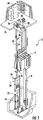
FIG. 1 is a schematic diagram of an elevator system employing an electronic safety actuation device to the elevator car and/or counterweight; -
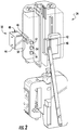
FIG. 2 is a schematic cross-sectional view of an exemplary electronic safety actuation device, in a non-engaging position according to an embodiment of the present disclosure; -
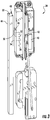
FIG. 3 is a schematic cross-sectional view of an exemplary electronic safety actuation device, in a non-engaging position according to another embodiment of the present disclosure; and -
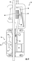
FIG. 4 is a schematic cross-sectional view of an exemplary electronic safety actuation device, in an engaging position according to an embodiment of the present disclosure. - For the purposes of promoting an understanding of the principles of the present disclosure, reference will now be made to the embodiments illustrated in the drawings, and specific language will be used to describe the same. It will nevertheless be understood that no limitation of the scope of this disclosure is thereby intended.
-
FIG. 1 shows an embodiment of an elevator system, generally indicated at 10. Theelevator system 10 includes an elevator component disposed in ahoistway 16. In an embodiment, the elevator component includes at least one of anelevator car 12 and acounterweight 20. Theelevator car 12 suspended by acable 14 in thehoistway 16. Theelevator car 12 is guided between car guide rails 18. Thecounterweight 20 is guided betweencounterweight guide rails 22 and is suspended on an opposite end of thecable 14. - Movement of the
elevator car 12 andcounterweight 20 in thehoistway 16 is provided by amotor 24 mounted in amachine room 26. Themotor 24 rotates asheave 28 around which thecable 14 extends to raise and lower theelevator car 12. - An electromechanical brake (not shown) located in the
machine room 26, electronic safety actuation devices,car safeties 34, and/orcounterweight safeties 36 act to stopelevator car 12 andcounterweight 20 if theelevator car 12 orcounterweight 20 exceed a set speed as it travels inside thehoistway 16. If theelevator car 12 orcounterweight 20 reaches a defined over-speed condition; thus, transmitting a signal to anelevator drive 38, which in turn cuts power to theelevator drive 38 and drops the brake to arrest movement of thesheave 28 and thereby arrest movement ofelevator car 12. - If, however,
cables 14 break or theelevator car 12 otherwise experiences a free-fall condition unaffected by the brake, the electronic safety actuation device may then act to actuate either or both of thecar safety 34 andcounterweight safety 36 to arrest movement of theelevator car 12 and/orcounterweight 20. -
FIG. 2 shows an embodiment of apower assembly 32 in use with an exemplary electronic safety actuation device that may be employed on the elevator car 12 (i.e., car safety 34) and/or counterweight 20 (i.e., counterweight safety 36). In an embodiment, the electronic safety actuation device includes anelectromagnetic component 40 and amagnetic brake 42. It will be appreciated that the exemplary safety device may include similar components as described below. - In order to power the
electromagnetic component 40, thepower assembly 32 is disposed within thehoistway 16. Thepower assembly 32 includes afirst power component 44 configured to provide power to asecond power component 46, wherein thesecond power component 46 is disposed on at least one of theelevator car 12 and thecounterweight 20. - In an embodiment, the
first power component 44 is configured to provide power to thesecond power component 46 via a direct connection or an indirect connection. For example, thefirst power component 44 may connect to thesecond power component 46 via a plug and socket connector, inductive charging, conductive charging, wireless power, and/or an outlet to name a few non-limiting examples. - The
first power component 44 includes afirst component connector 48, and thesecond power component 46 includes asecond component connector 50, such that when thefirst component connector 48 and thesecond component connector 50 are connected, power is transferred from thefirst power component 44 to thesecond power component 46. - The
second power component 46 further includes a firstpower storage device 52 operably coupled to thesecond component connector 50. The firstpower storage device 52, for example a battery to name one non-limiting example, is further coupled to an electronic safetyactuation device controller 54. The electronic safetyactuation device controller 54 is further coupled to a secondpower storage device 56. The secondpower storage device 56, for example a capacitor to name one non-limiting example, is further coupled to a portion of the electronic safety actuation device (e.g., the electromagnetic component 40), and is configured to activate the safety actuation device based in part on an actuation command. - The electronic safety
actuation device controller 54 is in communication with theelevator drive 38 via a communication module (not shown) disposed on the electronic safetyactuation device controller 54. In an embodiment, the communication module is configured to wirelessly exchange safety signals with theelevator drive 38. It will be appreciated that the communication module may be separate from the electronicsafety actuation controller 54. - In an embodiment, the
first power component 44 may be disposed within thehoistway 16 and operably coupled to the power source without the need of a traveling cable. In the embodiment shown inFIG. 1 ,first power component 44 is disposed at the top of thehoistway 16 on a support adjacent to the car guide rails 18. Anotherfirst power component 44 may be disposed at the bottom of thehoistway 16 on a support adjacent to the counterweight guide rails 22. In this embodiment, when theelevator car 12 is parked at the top of thehoistway 16, thecounterweight 20 is at the bottom of the hoistway. - In an embodiment, the
first power component 44 may be placed at locations along thehoistway 16 corresponding to positions of thecounterweight 20 when theelevator car 12 is stopped at each of the floors in the building, or at some subset of floors. - In another embodiment, as shown in
FIG. 3 , thefirst power component 44 may be a power rail to name one non-limiting example. Thus, it will be appreciated that thefirst power component 44 may be disposed in any location, or at multiple locations within thehoistway 16. Thesecond power component 46 is operably coupled to a portion of theelevator car 12 and/or counterweight 20 (e.g., the electronic safety actuation device, thecar safety 34 and/or the counterweight safety 36). - During typical operation, the
electromagnetic component 40 is a keeper configured to hold themagnetic brake 42 in a non-engaging position without power needed. Themagnetic brake 42 provides a sufficient magnetic attraction force in a direction toward theelectromagnetic component 40 to hold themagnetic brake 42 in the non-engaging position. - During an overspeed or other condition requiring braking, the
elevator drive 38 may wirelessly transmit a safety signal to the electronic safetyactuation device controller 54 to actuate theelectromagnetic component 40. In one embodiment, the electronic safetyactuation device controller 54 may itself sense the overspeed or other condition requiring braking and actuate theelectromagnetic component 40. Upon receipt of the safety signal, the electronic safetyactuation device controller 54 may issue an actuation command to theelectromagnetic component 40 to propel themagnetic brake 42 towards a guide rail into an engaging position by using the power from the secondpower storage device 56. - In the rail-engaging position, illustrated in
FIG. 4 , the exemplarymagnetic brake 42 is magnetically attached to the car guide rail 18 (or counterweight guide rails 22). Themagnetic brake 42 is operably coupled to asafety brake 58 by a rod orsmall linkage bar 60. Themagnetic brake 42, in the rail-engaging position, pushes/pulls thesafety brake 58 in an upward direction due to the relative upward movement of themagnetic brake 42 relative to the descendingelevator car 12. Thesafety brake 58 engages the car guide rail 18 (or counterweight guide rails 22) when themagnetic brake 42 pushes/pulls thesafety brake 58 in the upward direction. A wedge-shapedportion 62 of thesafety brake 58 allows asafety brake pad 64 to move toward and engage with the car guide rail 18 (or counterweight guide rails 22) upon upward movement of themagnetic brake 42 and therod 60. - The first
power storage device 52 is able to maintain or restore the stored power when thefirst component connector 48 is connected to thesecond component connector 50. This is accomplished when thefirst power component 44 is positioned to be adjacent to thesecond power component 46 such that thefirst component connector 48 may engage or mate with thesecond component connector 50. For example, when theelevator car 12 is stationary at a landing (e.g., top) or running in thehoistway 16, thefirst power component 44 is positioned to be adjacent to thesecond power component 46 such that thefirst component connector 48 may engage or mate with thesecond component connector 50. Power may then be transferred from thefirst power component 44 to the firstpower storage device 52 via thesecond power connector 50. This arrangement, therefore, eliminates the need for a travelling cable to power the electronic safety actuation device (connected to thecar safety 34 and/or connected to the counterweight safety 36). - It will therefore be appreciated that the
present elevator system 10 includes apower assembly 32 employed on an electronic safety actuation device (connected tocar safeties 34, and/or counterweight safeties 36) to actuate the safety without the need of additional traveling cables for power; thus, decreasing the costs of material and installation time of theelevator system 10. - While the disclosure has been illustrated and described in detail in the drawings and foregoing description, the same is to be considered as illustrative and not restrictive in character, it being understood that only certain embodiments have been shown and described and that all changes and modifications that come within the spirit of the disclosure are desired to be protected.
Claims (15)
- An elevator system comprising:a hoistway;an elevator component disposed in the hoistway; anda power assembly disposed in the hoistway, the power assembly comprising:a first power component disposed in the hoistway, the first power component comprising a first power connection; anda second power component operably coupled to the elevator component;wherein the first power component is configured to provide wireless power to the second power component.
- The elevator system of claim 1, wherein the second power component is configured to connect to the first power component via a direct connection or an indirect connection.
- The elevator system of claim 1 or 2, wherein the first power component is operably coupled to a power source.
- The elevator system of any preceding claim, wherein the second power component comprises:a second power connection;a first power storage device operably coupled to the second power connector;a safety actuation controller comprising a communication module, the safety actuation controller operably coupled to the first power storage device; anda second power storage device operably coupled to the safety actuation controller.
- The elevator system of any preceding claim, further comprising a guide rail disposed in the hoistway; the guide rail configured to engage the elevator component and direct the course of travel of the elevator component, and wherein preferably the first power component is operably coupled to the guide rail.
- The elevator system of claim 5, further comprising a safety device operably coupled to the elevator component, the safety device configured to engage the guide rail, and wherein preferably the second power component is operably coupled to the safety device.
- The elevator system of any preceding claim, wherein the elevator component comprises at least one of an elevator car and a counterweight.
- The elevator system of claim 7, further comprising an elevator drive operably coupled to the elevator car.
- The elevator system of any of claims 4 to 8, wherein the communication module is configured to wirelessly exchange safety signals with the elevator controller.
- An elevator safety device comprising:a power component comprising:a first power storage device;a safety actuation controller operably coupled to the first power storage device;a second power storage device operably coupled to the safety actuation controller; anda first connector operably coupled to the first power storage device; andan electromagnetic component operably connected to the power component, wherein the electromagnetic component is configured generate an actuation or a reset.
- The electronic safety device of claim 10, further comprising:a magnetic brake disposed adjacent to the electromagnetic component, the magnetic brake configured to move between an engaging position and a non-engaging position based in part on a hold force.
- The electronic safety device of claim 10 or 11, wherein the safety actuation controller comprises a communication module.
- The electronic safety device of claim 12, wherein the communication module is configured to wirelessly receive and transmit safety signals.
- The electronic safety device of any of claims 10 to 13, further comprising a second connector configured to engage the first connector.
- The electronic safety device of claim 14, wherein the second connector is removable.
Applications Claiming Priority (1)
| Application Number | Priority Date | Filing Date | Title |
|---|---|---|---|
| US15/091,246 US10252884B2 (en) | 2016-04-05 | 2016-04-05 | Wirelessly powered elevator electronic safety device |
Publications (3)
| Publication Number | Publication Date |
|---|---|
| EP3228573A2 true EP3228573A2 (en) | 2017-10-11 |
| EP3228573A3 EP3228573A3 (en) | 2018-03-14 |
| EP3228573B1 EP3228573B1 (en) | 2020-04-29 |
Family
ID=58489644
Family Applications (1)
| Application Number | Title | Priority Date | Filing Date |
|---|---|---|---|
| EP17165080.7A Not-in-force EP3228573B1 (en) | 2016-04-05 | 2017-04-05 | Electronic safety device with a power assembly |
Country Status (3)
| Country | Link |
|---|---|
| US (1) | US10252884B2 (en) |
| EP (1) | EP3228573B1 (en) |
| CN (1) | CN107434196B (en) |
Families Citing this family (9)
| Publication number | Priority date | Publication date | Assignee | Title |
|---|---|---|---|---|
| JP6807753B2 (en) * | 2014-06-12 | 2021-01-06 | オーチス エレベータ カンパニーOtis Elevator Company | Brake member drive mechanism |
| EP3154891B1 (en) * | 2014-06-12 | 2018-12-12 | Otis Elevator Company | Braking system resetting mechanism for a hoisted structure |
| US10112803B2 (en) * | 2016-04-01 | 2018-10-30 | Otis Elevator Company | Protection assembly for elevator braking assembly speed sensing device and method |
| US20180162693A1 (en) * | 2016-12-13 | 2018-06-14 | Otis Elevator Company | Speed detection means for elevator or counterweight |
| US11078045B2 (en) * | 2018-05-15 | 2021-08-03 | Otis Elevator Company | Electronic safety actuator for lifting a safety wedge of an elevator |
| EP3604196B1 (en) | 2018-08-03 | 2023-04-26 | Otis Elevator Company | Electronic safety actuator assembly for elevator system |
| EP3617120B1 (en) | 2018-08-30 | 2024-07-24 | Otis Elevator Company | Elevator electrical safety actuator control |
| EP3733584A1 (en) * | 2019-05-03 | 2020-11-04 | Otis Elevator Company | Combined safety brake and safety actuation mechanism |
| ES2821007B2 (en) * | 2019-09-06 | 2022-02-21 | Orona S Coop | Electromechanical parachute device for lifting devices |
Family Cites Families (35)
| Publication number | Priority date | Publication date | Assignee | Title |
|---|---|---|---|---|
| US4011928A (en) | 1975-06-06 | 1977-03-15 | Westinghouse Electric Corporation | Elevator system |
| CN2036939U (en) * | 1988-10-16 | 1989-05-03 | 杜立法 | Safety device for elevator |
| JP3381350B2 (en) * | 1993-02-03 | 2003-02-24 | 株式会社日立製作所 | Safety gear for elevators and elevators |
| US5495919A (en) | 1994-04-25 | 1996-03-05 | Otis Elevator Company | Safety brake apparatus for an elevator car or counterweight |
| US5782319A (en) | 1996-02-12 | 1998-07-21 | Montgomery Kone Inc. | Elevator car and counterweight safety |
| US5732795A (en) * | 1996-04-10 | 1998-03-31 | Otis Elevator Company | Power and communication for elevator car without traveling cable |
| US6196355B1 (en) * | 1999-03-26 | 2001-03-06 | Otis Elevator Company | Elevator rescue system |
| ATE333432T1 (en) * | 1999-05-25 | 2006-08-15 | Inventio Ag | DEVICE FOR TRANSFERRING ENERGY TO A VEHICLE OF A TRANSPORT SYSTEM |
| US6457569B2 (en) | 1999-10-27 | 2002-10-01 | Otis Elevator Company | Rotary actuated overspeed safety device |
| JP3857508B2 (en) * | 2000-08-29 | 2006-12-13 | 株式会社日立製作所 | Elevator equipment |
| JP3915414B2 (en) * | 2001-02-21 | 2007-05-16 | 株式会社日立製作所 | Elevator |
| CA2346519A1 (en) * | 2001-04-30 | 2002-10-30 | Michael J. Beus | Apparatus and method for generating power onboard a hoist conveyance |
| JP4553535B2 (en) * | 2001-09-28 | 2010-09-29 | 三菱電機株式会社 | Elevator equipment |
| US6629583B2 (en) * | 2001-12-21 | 2003-10-07 | Otis Elevator Company | Fixture for an elevator system |
| DE50309764D1 (en) | 2002-04-02 | 2008-06-19 | Inventio Ag | Device for engaging a safety gear for an elevator car |
| MY135853A (en) | 2003-02-04 | 2008-07-31 | Inventio Ag | Safety device for an elevator |
| US7097001B2 (en) * | 2003-11-12 | 2006-08-29 | Inventio Ag | Elevator car door movement restrictor |
| CN100455502C (en) * | 2004-05-27 | 2009-01-28 | 三菱电机株式会社 | Elevator device |
| CN101098823B (en) * | 2005-01-11 | 2011-02-09 | 奥蒂斯电梯公司 | Method for performing an elevator rescue run and the elevator |
| CN101146729B (en) * | 2005-04-01 | 2011-02-02 | 三菱电机株式会社 | Elevator power supply system |
| BRPI0601926B1 (en) * | 2005-06-17 | 2018-06-12 | Inventio Aktiengesellschaft | BRAKE PARACHUTE DEVICE |
| WO2008117423A1 (en) * | 2007-03-27 | 2008-10-02 | Mitsubishi Electric Corporation | Brake device for elevator |
| GB2458001B (en) | 2008-01-18 | 2010-12-08 | Kone Corp | An elevator hoist rope, an elevator and method |
| FI121066B (en) | 2009-03-31 | 2010-06-30 | Kone Corp | Lift system |
| PH12013501088A1 (en) | 2010-12-17 | 2013-07-08 | Inventio Ag | Lift installation comprising car and counterweight |
| AU2011344429B2 (en) | 2010-12-17 | 2017-03-30 | Inventio Ag | Arrangement for actuating and restoring an intercepting apparatus |
| US9169104B2 (en) | 2010-12-17 | 2015-10-27 | Inventio Ag | Activating a safety gear |
| US9919899B2 (en) | 2011-12-09 | 2018-03-20 | Inventio Ag | Actuation of a safety brake |
| WO2013092239A1 (en) | 2011-12-21 | 2013-06-27 | Inventio Ag | Actuator for lift brake |
| CN104684834B (en) | 2012-09-25 | 2017-10-20 | 奥的斯电梯公司 | Low top or the indemnifying measure of low pit elevator |
| CN104718148B (en) | 2012-10-18 | 2016-10-12 | 因温特奥股份公司 | The safety device of lift facility |
| US9837860B2 (en) * | 2014-05-05 | 2017-12-05 | Witricity Corporation | Wireless power transmission systems for elevators |
| JP6807753B2 (en) | 2014-06-12 | 2021-01-06 | オーチス エレベータ カンパニーOtis Elevator Company | Brake member drive mechanism |
| CN106477430B (en) * | 2015-09-01 | 2020-11-03 | 奥的斯电梯公司 | Elevator Wireless Communication and Power Transmission System |
| US10315886B2 (en) * | 2016-04-11 | 2019-06-11 | Otis Elevator Company | Electronic safety actuation device with a power assembly, magnetic brake and electromagnetic component |
-
2016
- 2016-04-05 US US15/091,246 patent/US10252884B2/en active Active
-
2017
- 2017-04-05 CN CN201710219064.4A patent/CN107434196B/en not_active Expired - Fee Related
- 2017-04-05 EP EP17165080.7A patent/EP3228573B1/en not_active Not-in-force
Non-Patent Citations (1)
| Title |
|---|
| None |
Also Published As
| Publication number | Publication date |
|---|---|
| CN107434196A (en) | 2017-12-05 |
| US20170283215A1 (en) | 2017-10-05 |
| CN107434196B (en) | 2020-09-22 |
| US10252884B2 (en) | 2019-04-09 |
| EP3228573B1 (en) | 2020-04-29 |
| EP3228573A3 (en) | 2018-03-14 |
Similar Documents
| Publication | Publication Date | Title |
|---|---|---|
| US10252884B2 (en) | Wirelessly powered elevator electronic safety device | |
| US10315886B2 (en) | Electronic safety actuation device with a power assembly, magnetic brake and electromagnetic component | |
| CN106395544B (en) | Electromagnetic safety trigger | |
| EP3643666B1 (en) | Elevator system | |
| TWI754429B (en) | Self-propelled elevators, elevator brake systems, and method of controlling elevator systems | |
| EP3331798B1 (en) | Device and method for actuating an elevator safety brake | |
| EP3147248B1 (en) | Braking system for a hoisted structure and method of controlling braking a hoisted strucuture | |
| EP2763927B1 (en) | Elevator braking system | |
| CN104822614A (en) | Elevator device | |
| CN106516931A (en) | Actuator assembly for an elevator governor system and method | |
| CN106477416A (en) | Method for moving elevator car | |
| CN107445013B (en) | Brake system for elevator system | |
| JPH033875A (en) | Elevator driven by linear motor | |
| EP4400466B1 (en) | Emergency stop system for elevator | |
| EP3666703B1 (en) | Electrical power transmission to elevator system cars | |
| EP3587327B1 (en) | Electronic safety actuator electromagnetic guidance | |
| JPH0715668U (en) | Braking equipment for low press elevators | |
| EP3929130B1 (en) | Safety link with a pulley | |
| CN205419394U (en) | Electrical control promptly stays and stops protection device for lift | |
| JP2006225052A (en) | Multi-car elevator | |
| HK1236175A1 (en) | Braking system for a hoisted structure and method of controlling braking a hoisted structure |
Legal Events
| Date | Code | Title | Description |
|---|---|---|---|
| PUAI | Public reference made under article 153(3) epc to a published international application that has entered the european phase |
Free format text: ORIGINAL CODE: 0009012 |
|
| STAA | Information on the status of an ep patent application or granted ep patent |
Free format text: STATUS: THE APPLICATION HAS BEEN PUBLISHED |
|
| AK | Designated contracting states |
Kind code of ref document: A2 Designated state(s): AL AT BE BG CH CY CZ DE DK EE ES FI FR GB GR HR HU IE IS IT LI LT LU LV MC MK MT NL NO PL PT RO RS SE SI SK SM TR |
|
| AX | Request for extension of the european patent |
Extension state: BA ME |
|
| REG | Reference to a national code |
Ref country code: DE Ref legal event code: R079 Ref document number: 602017015490 Country of ref document: DE Free format text: PREVIOUS MAIN CLASS: B66B0005040000 Ipc: B66B0005220000 |
|
| PUAL | Search report despatched |
Free format text: ORIGINAL CODE: 0009013 |
|
| AK | Designated contracting states |
Kind code of ref document: A3 Designated state(s): AL AT BE BG CH CY CZ DE DK EE ES FI FR GB GR HR HU IE IS IT LI LT LU LV MC MK MT NL NO PL PT RO RS SE SI SK SM TR |
|
| AX | Request for extension of the european patent |
Extension state: BA ME |
|
| RIC1 | Information provided on ipc code assigned before grant |
Ipc: B66B 7/00 20060101ALI20180206BHEP Ipc: B66B 5/22 20060101AFI20180206BHEP |
|
| STAA | Information on the status of an ep patent application or granted ep patent |
Free format text: STATUS: REQUEST FOR EXAMINATION WAS MADE |
|
| 17P | Request for examination filed |
Effective date: 20180911 |
|
| RBV | Designated contracting states (corrected) |
Designated state(s): AL AT BE BG CH CY CZ DE DK EE ES FI FR GB GR HR HU IE IS IT LI LT LU LV MC MK MT NL NO PL PT RO RS SE SI SK SM TR |
|
| GRAP | Despatch of communication of intention to grant a patent |
Free format text: ORIGINAL CODE: EPIDOSNIGR1 |
|
| STAA | Information on the status of an ep patent application or granted ep patent |
Free format text: STATUS: GRANT OF PATENT IS INTENDED |
|
| INTG | Intention to grant announced |
Effective date: 20191217 |
|
| GRAS | Grant fee paid |
Free format text: ORIGINAL CODE: EPIDOSNIGR3 |
|
| GRAA | (expected) grant |
Free format text: ORIGINAL CODE: 0009210 |
|
| STAA | Information on the status of an ep patent application or granted ep patent |
Free format text: STATUS: THE PATENT HAS BEEN GRANTED |
|
| AK | Designated contracting states |
Kind code of ref document: B1 Designated state(s): AL AT BE BG CH CY CZ DE DK EE ES FI FR GB GR HR HU IE IS IT LI LT LU LV MC MK MT NL NO PL PT RO RS SE SI SK SM TR |
|
| REG | Reference to a national code |
Ref country code: GB Ref legal event code: FG4D |
|
| REG | Reference to a national code |
Ref country code: CH Ref legal event code: EP |
|
| REG | Reference to a national code |
Ref country code: DE Ref legal event code: R096 Ref document number: 602017015490 Country of ref document: DE |
|
| REG | Reference to a national code |
Ref country code: AT Ref legal event code: REF Ref document number: 1263013 Country of ref document: AT Kind code of ref document: T Effective date: 20200515 |
|
| REG | Reference to a national code |
Ref country code: IE Ref legal event code: FG4D |
|
| REG | Reference to a national code |
Ref country code: NL Ref legal event code: MP Effective date: 20200429 |
|
| REG | Reference to a national code |
Ref country code: LT Ref legal event code: MG4D |
|
| PG25 | Lapsed in a contracting state [announced via postgrant information from national office to epo] |
Ref country code: IS Free format text: LAPSE BECAUSE OF FAILURE TO SUBMIT A TRANSLATION OF THE DESCRIPTION OR TO PAY THE FEE WITHIN THE PRESCRIBED TIME-LIMIT Effective date: 20200829 Ref country code: FI Free format text: LAPSE BECAUSE OF FAILURE TO SUBMIT A TRANSLATION OF THE DESCRIPTION OR TO PAY THE FEE WITHIN THE PRESCRIBED TIME-LIMIT Effective date: 20200429 Ref country code: PT Free format text: LAPSE BECAUSE OF FAILURE TO SUBMIT A TRANSLATION OF THE DESCRIPTION OR TO PAY THE FEE WITHIN THE PRESCRIBED TIME-LIMIT Effective date: 20200831 Ref country code: NO Free format text: LAPSE BECAUSE OF FAILURE TO SUBMIT A TRANSLATION OF THE DESCRIPTION OR TO PAY THE FEE WITHIN THE PRESCRIBED TIME-LIMIT Effective date: 20200729 Ref country code: SE Free format text: LAPSE BECAUSE OF FAILURE TO SUBMIT A TRANSLATION OF THE DESCRIPTION OR TO PAY THE FEE WITHIN THE PRESCRIBED TIME-LIMIT Effective date: 20200429 Ref country code: LT Free format text: LAPSE BECAUSE OF FAILURE TO SUBMIT A TRANSLATION OF THE DESCRIPTION OR TO PAY THE FEE WITHIN THE PRESCRIBED TIME-LIMIT Effective date: 20200429 Ref country code: GR Free format text: LAPSE BECAUSE OF FAILURE TO SUBMIT A TRANSLATION OF THE DESCRIPTION OR TO PAY THE FEE WITHIN THE PRESCRIBED TIME-LIMIT Effective date: 20200730 |
|
| REG | Reference to a national code |
Ref country code: AT Ref legal event code: MK05 Ref document number: 1263013 Country of ref document: AT Kind code of ref document: T Effective date: 20200429 |
|
| PG25 | Lapsed in a contracting state [announced via postgrant information from national office to epo] |
Ref country code: BG Free format text: LAPSE BECAUSE OF FAILURE TO SUBMIT A TRANSLATION OF THE DESCRIPTION OR TO PAY THE FEE WITHIN THE PRESCRIBED TIME-LIMIT Effective date: 20200729 Ref country code: HR Free format text: LAPSE BECAUSE OF FAILURE TO SUBMIT A TRANSLATION OF THE DESCRIPTION OR TO PAY THE FEE WITHIN THE PRESCRIBED TIME-LIMIT Effective date: 20200429 Ref country code: LV Free format text: LAPSE BECAUSE OF FAILURE TO SUBMIT A TRANSLATION OF THE DESCRIPTION OR TO PAY THE FEE WITHIN THE PRESCRIBED TIME-LIMIT Effective date: 20200429 Ref country code: RS Free format text: LAPSE BECAUSE OF FAILURE TO SUBMIT A TRANSLATION OF THE DESCRIPTION OR TO PAY THE FEE WITHIN THE PRESCRIBED TIME-LIMIT Effective date: 20200429 |
|
| PG25 | Lapsed in a contracting state [announced via postgrant information from national office to epo] |
Ref country code: NL Free format text: LAPSE BECAUSE OF FAILURE TO SUBMIT A TRANSLATION OF THE DESCRIPTION OR TO PAY THE FEE WITHIN THE PRESCRIBED TIME-LIMIT Effective date: 20200429 Ref country code: AL Free format text: LAPSE BECAUSE OF FAILURE TO SUBMIT A TRANSLATION OF THE DESCRIPTION OR TO PAY THE FEE WITHIN THE PRESCRIBED TIME-LIMIT Effective date: 20200429 |
|
| PG25 | Lapsed in a contracting state [announced via postgrant information from national office to epo] |
Ref country code: AT Free format text: LAPSE BECAUSE OF FAILURE TO SUBMIT A TRANSLATION OF THE DESCRIPTION OR TO PAY THE FEE WITHIN THE PRESCRIBED TIME-LIMIT Effective date: 20200429 Ref country code: ES Free format text: LAPSE BECAUSE OF FAILURE TO SUBMIT A TRANSLATION OF THE DESCRIPTION OR TO PAY THE FEE WITHIN THE PRESCRIBED TIME-LIMIT Effective date: 20200429 Ref country code: DK Free format text: LAPSE BECAUSE OF FAILURE TO SUBMIT A TRANSLATION OF THE DESCRIPTION OR TO PAY THE FEE WITHIN THE PRESCRIBED TIME-LIMIT Effective date: 20200429 Ref country code: RO Free format text: LAPSE BECAUSE OF FAILURE TO SUBMIT A TRANSLATION OF THE DESCRIPTION OR TO PAY THE FEE WITHIN THE PRESCRIBED TIME-LIMIT Effective date: 20200429 Ref country code: IT Free format text: LAPSE BECAUSE OF FAILURE TO SUBMIT A TRANSLATION OF THE DESCRIPTION OR TO PAY THE FEE WITHIN THE PRESCRIBED TIME-LIMIT Effective date: 20200429 Ref country code: CZ Free format text: LAPSE BECAUSE OF FAILURE TO SUBMIT A TRANSLATION OF THE DESCRIPTION OR TO PAY THE FEE WITHIN THE PRESCRIBED TIME-LIMIT Effective date: 20200429 Ref country code: SM Free format text: LAPSE BECAUSE OF FAILURE TO SUBMIT A TRANSLATION OF THE DESCRIPTION OR TO PAY THE FEE WITHIN THE PRESCRIBED TIME-LIMIT Effective date: 20200429 Ref country code: EE Free format text: LAPSE BECAUSE OF FAILURE TO SUBMIT A TRANSLATION OF THE DESCRIPTION OR TO PAY THE FEE WITHIN THE PRESCRIBED TIME-LIMIT Effective date: 20200429 |
|
| REG | Reference to a national code |
Ref country code: DE Ref legal event code: R097 Ref document number: 602017015490 Country of ref document: DE |
|
| PG25 | Lapsed in a contracting state [announced via postgrant information from national office to epo] |
Ref country code: PL Free format text: LAPSE BECAUSE OF FAILURE TO SUBMIT A TRANSLATION OF THE DESCRIPTION OR TO PAY THE FEE WITHIN THE PRESCRIBED TIME-LIMIT Effective date: 20200429 Ref country code: SK Free format text: LAPSE BECAUSE OF FAILURE TO SUBMIT A TRANSLATION OF THE DESCRIPTION OR TO PAY THE FEE WITHIN THE PRESCRIBED TIME-LIMIT Effective date: 20200429 |
|
| PLBE | No opposition filed within time limit |
Free format text: ORIGINAL CODE: 0009261 |
|
| STAA | Information on the status of an ep patent application or granted ep patent |
Free format text: STATUS: NO OPPOSITION FILED WITHIN TIME LIMIT |
|
| 26N | No opposition filed |
Effective date: 20210201 |
|
| PG25 | Lapsed in a contracting state [announced via postgrant information from national office to epo] |
Ref country code: SI Free format text: LAPSE BECAUSE OF FAILURE TO SUBMIT A TRANSLATION OF THE DESCRIPTION OR TO PAY THE FEE WITHIN THE PRESCRIBED TIME-LIMIT Effective date: 20200429 |
|
| PG25 | Lapsed in a contracting state [announced via postgrant information from national office to epo] |
Ref country code: MC Free format text: LAPSE BECAUSE OF FAILURE TO SUBMIT A TRANSLATION OF THE DESCRIPTION OR TO PAY THE FEE WITHIN THE PRESCRIBED TIME-LIMIT Effective date: 20200429 |
|
| GBPC | Gb: european patent ceased through non-payment of renewal fee |
Effective date: 20210405 |
|
| PG25 | Lapsed in a contracting state [announced via postgrant information from national office to epo] |
Ref country code: LU Free format text: LAPSE BECAUSE OF NON-PAYMENT OF DUE FEES Effective date: 20210405 |
|
| REG | Reference to a national code |
Ref country code: BE Ref legal event code: MM Effective date: 20210430 |
|
| PG25 | Lapsed in a contracting state [announced via postgrant information from national office to epo] |
Ref country code: LI Free format text: LAPSE BECAUSE OF NON-PAYMENT OF DUE FEES Effective date: 20210430 Ref country code: CH Free format text: LAPSE BECAUSE OF NON-PAYMENT OF DUE FEES Effective date: 20210430 Ref country code: GB Free format text: LAPSE BECAUSE OF NON-PAYMENT OF DUE FEES Effective date: 20210405 |
|
| PG25 | Lapsed in a contracting state [announced via postgrant information from national office to epo] |
Ref country code: IE Free format text: LAPSE BECAUSE OF NON-PAYMENT OF DUE FEES Effective date: 20210405 |
|
| PG25 | Lapsed in a contracting state [announced via postgrant information from national office to epo] |
Ref country code: BE Free format text: LAPSE BECAUSE OF NON-PAYMENT OF DUE FEES Effective date: 20210430 |
|
| PGFP | Annual fee paid to national office [announced via postgrant information from national office to epo] |
Ref country code: FR Payment date: 20230321 Year of fee payment: 7 |
|
| PG25 | Lapsed in a contracting state [announced via postgrant information from national office to epo] |
Ref country code: HU Free format text: LAPSE BECAUSE OF FAILURE TO SUBMIT A TRANSLATION OF THE DESCRIPTION OR TO PAY THE FEE WITHIN THE PRESCRIBED TIME-LIMIT; INVALID AB INITIO Effective date: 20170405 |
|
| PG25 | Lapsed in a contracting state [announced via postgrant information from national office to epo] |
Ref country code: CY Free format text: LAPSE BECAUSE OF FAILURE TO SUBMIT A TRANSLATION OF THE DESCRIPTION OR TO PAY THE FEE WITHIN THE PRESCRIBED TIME-LIMIT Effective date: 20200429 |
|
| PGFP | Annual fee paid to national office [announced via postgrant information from national office to epo] |
Ref country code: DE Payment date: 20230321 Year of fee payment: 7 |
|
| PG25 | Lapsed in a contracting state [announced via postgrant information from national office to epo] |
Ref country code: MK Free format text: LAPSE BECAUSE OF FAILURE TO SUBMIT A TRANSLATION OF THE DESCRIPTION OR TO PAY THE FEE WITHIN THE PRESCRIBED TIME-LIMIT Effective date: 20200429 |
|
| PG25 | Lapsed in a contracting state [announced via postgrant information from national office to epo] |
Ref country code: MT Free format text: LAPSE BECAUSE OF FAILURE TO SUBMIT A TRANSLATION OF THE DESCRIPTION OR TO PAY THE FEE WITHIN THE PRESCRIBED TIME-LIMIT Effective date: 20200429 |
|
| REG | Reference to a national code |
Ref country code: DE Ref legal event code: R119 Ref document number: 602017015490 Country of ref document: DE |
|
| PG25 | Lapsed in a contracting state [announced via postgrant information from national office to epo] |
Ref country code: DE Free format text: LAPSE BECAUSE OF NON-PAYMENT OF DUE FEES Effective date: 20241105 |
|
| PG25 | Lapsed in a contracting state [announced via postgrant information from national office to epo] |
Ref country code: FR Free format text: LAPSE BECAUSE OF NON-PAYMENT OF DUE FEES Effective date: 20240430 |
|
| PG25 | Lapsed in a contracting state [announced via postgrant information from national office to epo] |
Ref country code: FR Free format text: LAPSE BECAUSE OF NON-PAYMENT OF DUE FEES Effective date: 20240430 Ref country code: DE Free format text: LAPSE BECAUSE OF NON-PAYMENT OF DUE FEES Effective date: 20241105 |
|
| PG25 | Lapsed in a contracting state [announced via postgrant information from national office to epo] |
Ref country code: TR Free format text: LAPSE BECAUSE OF FAILURE TO SUBMIT A TRANSLATION OF THE DESCRIPTION OR TO PAY THE FEE WITHIN THE PRESCRIBED TIME-LIMIT Effective date: 20200429 |