EP3228534A1 - Pressure bulkhead apparatus - Google Patents
Pressure bulkhead apparatus Download PDFInfo
- Publication number
- EP3228534A1 EP3228534A1 EP17163535.2A EP17163535A EP3228534A1 EP 3228534 A1 EP3228534 A1 EP 3228534A1 EP 17163535 A EP17163535 A EP 17163535A EP 3228534 A1 EP3228534 A1 EP 3228534A1
- Authority
- EP
- European Patent Office
- Prior art keywords
- fitting
- assembly
- fuselage
- beams
- stringer
- Prior art date
- Legal status (The legal status is an assumption and is not a legal conclusion. Google has not performed a legal analysis and makes no representation as to the accuracy of the status listed.)
- Granted
Links
Images




Classifications
-
- B—PERFORMING OPERATIONS; TRANSPORTING
- B64—AIRCRAFT; AVIATION; COSMONAUTICS
- B64C—AEROPLANES; HELICOPTERS
- B64C1/00—Fuselages; Constructional features common to fuselages, wings, stabilising surfaces or the like
- B64C1/06—Frames; Stringers; Longerons ; Fuselage sections
- B64C1/10—Bulkheads
-
- B—PERFORMING OPERATIONS; TRANSPORTING
- B64—AIRCRAFT; AVIATION; COSMONAUTICS
- B64C—AEROPLANES; HELICOPTERS
- B64C1/00—Fuselages; Constructional features common to fuselages, wings, stabilising surfaces or the like
- B64C1/06—Frames; Stringers; Longerons ; Fuselage sections
- B64C1/068—Fuselage sections
- B64C1/069—Joining arrangements therefor
Definitions
- This patent relates generally to aircraft and, more particularly, to pressure bulkhead apparatus.
- a fuselage of commercial aircraft typically includes fuselage portions or sections that are individually assembled and then combined or attached to form the cabin.
- An aft pressure bulkhead and a forward pressure bulkhead are installed to form a barrier between an internal pressurized area (e.g., a cabin, a cockpit, etc.) and an external, unpressurized area.
- An example bulkhead apparatus includes a frame and a plurality of beams radially spaced relative to a longitudinal axis of the frame.
- a beam from the plurality of beams has a first end and a second end.
- a beam end assembly couples the second end of the beam and a stringer of a fuselage. The beam end assembly enables the second end of the beam to move relative to at least one of the frame or the stringer.
- an example aircraft in another example, includes a fuselage having stringers aligned along a length of the fuselage and a bulkhead coupled to the fuselage.
- the bulkhead has a web and beams.
- the beams are radially spaced relative to a longitudinal axis of the web.
- Each beam includes a first end and an opposing second end. The first end is radially inward adjacent a center of the web. The second end is radially outward adjacent a circumference of the web.
- a respective beam end assembly pivotally couples the second end of each beam and a respective one of the stringers.
- the beam end assemblies are configured to eliminate moment loading at an interface between the beams and the stringers.
- Another example bulkhead apparatus includes a beam having a first end and a second end opposite the first end. The first end is coupled to the hub. The second end is radially outward relative to a frame. A first fitting is coupled to the second end of the beam. A second fitting has a first portion and a second portion. The first portion is coupled to the frame and the second portion is to couple to a stringer of a fuselage. A linkage assembly is pivotally coupled to at least one of the first fitting or second fitting.
- any part e.g., a layer, film, area, or plate
- the referenced part is either in contact with the other part, or that the referenced part is above the other part with one or more intermediate part(s) located there between.
- Stating that any part is in direct contact with another part means that there is no intermediate part between the two parts.
- substantially and approximately mean within about 10% (e.g., 10 degrees) different than the number at issue.
- substantially perpendicular means 90 degrees plus or minus 10%.
- approximately 90 degrees means 90 degrees plus or minus 10% (e.g., between about 81 degrees and 99 degrees).
- substantially parallel means 0 degrees plus or minus 10 degrees.
- pressure bulkheads to form a pressurized cabin of a fuselage. Additionally, pressure bulkheads transfer and/or discharge loads (e.g., forces) to the surrounding structure of the fuselage, for example, stringers, fuselage skin and/or other frame members.
- loads e.g., forces
- Some known pressure bulkheads have a dome profile that arches toward the aft end of the fuselage. The dome profile reduces internal stresses in the pressure bulkhead. However, the dome profile occupies a relatively large volume in a fuselage, which increases the space required for the pressure bulkhead.
- Some pressure bulkheads have a flat profile to enable the bulkhead to occupy significantly less space than domed pressure bulkheads.
- Some flat pressure bulkheads have a circular profile and include beams positioned in a grid pattern (e.g., a horizontal and vertical beam grid pattern).
- a grid pattern e.g., a horizontal and vertical beam grid pattern.
- such known flat bulkheads are typically coupled to a fuselage between adjacent stringers using a relatively large fitting and link assembly to transfer end loads from the pressure bulkhead to the stringers and skin of the fuselage.
- the beams of flat pressure bulkheads may not couple directly to fuselage stringers of an aircraft due to tolerances and/or additional loading on the stringers (e.g., as the fuselage expands and contracts due to pressure differentials).
- relatively heavy and/or large fittings may be required to transfer force loads from the beams to the stringers and skin of the aircraft.
- Some bulkheads may employ radially spaced beams instead of beams provided in the grid pattern. However, in some such examples, each of the radially spaced beams may be fixed to a respective stringer of the fuselage.
- the fixed coupling between the beams and the stringers may impart a large moment load (e.g., bending moments) to the stringer and/or skin of the aircraft.
- a connection or fitting between each beam and a respective stringer is relatively large.
- Such connections can add weight and complexity to the aircraft, which may reduce aircraft efficiency and result in increased fuel burn.
- Pressure bulkhead apparatus disclosed herein may significantly reduce manufacturing complexity, number of components, aircraft weight, and/or costs. More specifically, the example pressure bulkhead apparatus disclosed herein employ a beam end assembly to enable direct attachment between the example pressure bulkhead apparatus disclosed herein and a support structure (e.g., a stringer, and aft stringer, a former, a frame, etc.) of an aircraft, spaceship, and/or any other vehicle (e.g., a boat). More specifically, the beam end assembly disclosed herein directs or transfers tensile forces or loads to the support structure (e.g., of an aircraft), and can prevent or reduce transfer of moment loads (e.g., bending moments) to the support structure by enabling a rotational freedom between the beam end assembly and fuselage.
- a support structure e.g., a stringer, and aft stringer, a former, a frame, etc.
- any other vehicle e.g., a boat
- the beam end assembly disclosed herein directs or transfers ten
- preventing transfer of moment loads includes absolute zero transfer of moment loads or transfer of insignificant moment loads.
- insignificant moment loads means that the loads do not affect design aspects or characteristics (e.g., size, weight, material selection, etc.) of the beams, the beam end assembly and, more generally, the example pressure bulkhead apparatus disclosed herein.
- the pressure bulkhead apparatus disclosed herein may be designed without consideration for these insignificant moment loads.
- a reduced transfer of moment loads means moment loads that are approximately less than 15% (fifteen percent) of moment loads that would otherwise be transferred if the beams of the pressure bulkhead apparatus were fixed to the fuselage (i.e., the beam end assembly did not allow for any rotational freedom between the beam end assembly and the fuselage).
- the beam end assembly of the example pressure bulkhead apparatus provides a linkage assembly (e.g., a link and pins) to enable a rotational freedom between the beam end assembly and fuselage.
- the beam end assembly may prevent translational movement of the beam and/or bulkhead apparatus relative to the support structure to enable tensile loads from the bulkhead apparatus to transfer to the support structure of the aircraft (e.g., stingers and/or fuselage skin).
- a beam end assembly and/or a linkage assembly may include a link and a pin, a bushing, a bearing, a bolt and bearing assembly, and/or any other fastener or coupling to prevent or reduce transfer of moment loads from the pressure bulkhead apparatus to the stringers and skin of an aircraft.
- a pressure bulkhead apparatus disclosed herein employs beams radially oriented relative to a longitudinal axis of the fuselage of the example pressure bulkhead apparatus.
- the beams are radially oriented along a primary load path of the web and/or the bulkhead apparatus.
- the loads e.g., pressure loads and/or non-pressure loads
- the loads imparted to the web are transferred or aligned relative to the respective beams.
- Each radially outward end of the beams is coupled to a respective stringer of a fuselage using an additional structure (e.g., a fittings, angles, etc.) that transfers the loads (e.g., tensile, moment, shear loads) from the beams to the stringers and the skin.
- the outer ends of the beams of the example pressure bulkhead apparatus disclosed herein are configured (e.g., via a beam end assembly) to move or rotate such that a moment load is not transferred to the stringers and skin of the fuselage.
- the fitting of the example pressure bulkheads disclosed herein can be directly attached to a stringer of the fuselage, not between adjacent stringers as noted above.
- the beam end assembly of the bulkhead apparatus may direct loads from a primary load path of an aircraft directly to stringers aligned with the respective beams, which may prevent or reduce moment loads from transferring to the respective stringers and/or the fuselage structure (e.g., frames, skin, formers, etc.) adjacent the ends of the beams.
- the fuselage structure e.g., frames, skin, formers, etc.
- FIG. 1 illustrates an aircraft 100 implemented with a pressure bulkhead apparatus 102 constructed in accordance with the teachings of this disclosure.
- the example aircraft 100 of FIG. 1 includes a fuselage 104 having a cabin 106 defining an internal pressure region 108 between an aft pressure bulkhead 110 coupled to the fuselage 104 at aft end 112 (e.g., adjacent a tail) of the aircraft 100 and a forward pressure bulkhead 114 coupled to the fuselage 104 at a forward end 116 (e.g., adjacent a nose) of the aircraft 100.
- the aft pressure bulkhead 110 and the forward pressure bulkhead 114 form pressure barriers between the internal pressure region 108 and an external pressure region 118.
- the pressure bulkhead apparatus 102 disclosed herein may be used to implement the aft pressure bulkhead 110 and/or the forward pressure bulkhead 114.
- FIG. 2 is a perspective view of a fuselage portion 200 of the fuselage 104 of the aircraft 100 of FIG. 1 .
- the fuselage portion 200 of the illustrated example includes a plurality of frames 202 (e.g., formers) that define a cross-sectional shape of the fuselage 104.
- the fuselage portion 200 defines a longitudinal axis 204, which is perpendicular relative to a cross-section of the fuselage portion 200.
- Stringers 206 of the illustrated example span a length of the fuselage portion 200 between the frames 202.
- An outer skin 208 of the fuselage 104 is coupled to the stringers 206 of the fuselage 104.
- cabin pressure is at a pressure equivalent to a pressure at 6000 to 8000 feet (1828.8 to 2438.4 meters) above sea level, and atmospheric pressure is at a lower pressure.
- a pressure differential is maintained across the pressure bulkhead apparatus 102.
- pressure loads are imparted to the pressure bulkhead apparatus 102 in a direction 218 of the external pressure region 118.
- operational loads e.g., lift loads, drag loads, engine thrust loads, etc.
- the stringers 206 and/or the skin 208 are arranged to provide structural stability and integrity to the fuselage 104 by resisting the pressure loads and/or the operational loads.
- at least a portion of pressure loads and/or the operational loads e.g., from wings and empennage, from discrete masses such as the engine, etc.
- the forces imparted to the pressure bulkhead apparatus 102 may cause or generate moment loads (e.g., bending moments) at an interface 216 between the pressure bulkhead apparatus 102 and the fuselage 104.
- the pressure bulkhead apparatus 102 of the illustrated example transfers forces imparted to the pressure bulkhead apparatus 102 to the stringers 206 and/or the skin 208. Additionally, the pressure bulkhead apparatus 102 of the illustrated example may eliminate moment loads at the interface 216 between the pressure bulkhead apparatus 102 and the fuselage 104.
- FIG. 3 is a perspective view of the pressure bulkhead apparatus 102 of FIGS. 1 and 2 .
- the pressure bulkhead apparatus 102 of the illustrated example may implement the aft pressure bulkhead 110 and/or the forward pressure bulkhead 114 of FIG. 1 .
- the pressure bulkhead apparatus 102 of the illustrated example couples to a frame of the fuselage 104 (e.g., stringers, formers, frames (e.g., the frames 202 of FIG. 2 )). Additionally, the pressure bulkhead apparatus 102 of the illustrated example couples to forward stringers 302 (e.g., the stringers 206 positioned in the internal pressure region 108) and aft stringers 304 (e.g., the stringers 206 positioned in the external pressure region 118).
- forward stringers 302 e.g., the stringers 206 positioned in the internal pressure region 108
- aft stringers 304 e.g., the stringers 206 positioned in the external pressure region 118.
- a longitudinal axis 306 (e.g., a central axis) of the pressure bulkhead apparatus 102 aligns (e.g., coaxially aligns) with the longitudinal axis 204 of the fuselage 104.
- the longitudinal axis 306 is also the longitudinal axis of the frame 308. Portions of the aft stringers 304 and the skin 208 are omitted from FIG. 3 for clarity.
- the pressure bulkhead apparatus 102 of the illustrated example couples to a frame 308 (e.g., a chord, a ring, an annular plate, the frame 202, etc.) having a radius.
- the radius of the frame 308 of the illustrated example is similar to a radius of the fuselage 104.
- the frame 308 of the illustrated example includes a plurality of beams 312 (e.g., 20 beams) radially spaced relative to a longitudinal axis 306 of the pressure bulkhead apparatus 102 and the frame 308.
- the beams 312 are radially spaced at equidistant angles or intervals.
- the beams 312 are radially spaced at different or varying distances, angles or intervals relative to the longitudinal axis 306.
- Each of the beams 312 has a first end 314 adjacent the longitudinal axis 306 and a second end 316 adjacent the frame 308.
- the pressure bulkhead apparatus 102 includes a hub assembly 318 coaxially aligned with the longitudinal axis 306.
- the first ends 314 of the beams 312 are coupled to the hub assembly 318.
- the respective second ends 316 of the beams 312 project from the hub assembly 318 toward the frame 308.
- the pressure bulkhead apparatus 102 includes a web 320 coupled to the beams 312.
- the web 320 of the illustrated example is a substantially planar skin (e.g., a sheet-shaped member) that is concentrically aligned with the hub assembly 318.
- the beams 312 of the illustrated example are positioned against the web 320.
- the beams 312 of the illustrated example are each aligned relative to a radius of the web 320.
- the respective first ends 314 of the beams 312 are radially inward of the hub assembly 318 and the respective second ends 316 of the beams 312 are radially outward relative to a circumference of the web 320.
- the web 320 of the illustrated example carries pressure loads and/or other non-pressure loads exerted on the pressure bulkhead apparatus 102 (e.g., due to a pressure differential across the pressure bulkhead apparatus 102).
- each of the beams 312 of the pressure bulkhead apparatus 102 of the illustrated example includes a beam end assembly 324.
- the beam end assembly 324 directly couples the beams 312 to respective aft stringers 304. Additionally, to eliminate moment loads at the interface 216, the beam end assembly 324 permits rotation of the respective beams 312 relative the aft stringers 304. The beam end assembly 324 prevents translational motion of the beams 312 relative to the aft stringers 304 (e.g., in the aft-fore direction along the longitudinal axis 204 of the fuselage).
- the web 320 transfers loads to the stringers 206 (e.g., the aft stringers 304 and/or forward stringers 302) via the beams 312 and the beam end assembly 324 of each of the beams 312.
- the stringers 206 e.g., the aft stringers 304 and/or forward stringers 302
- FIG. 4 is an enlarged, partial view of the pressure bulkhead apparatus 102 of FIGS. 1-3 .
- the frame 308 of the pressure bulkhead apparatus 102 is partially shown and the web 320 is omitted in FIG. 4 for clarity.
- a beam 404 of the plurality of beams 312 includes a body 406 having a longitudinal axis 408 between the first end 314 of the beam 404 and the second end 316 of the beam 404 opposite the first end 314.
- the hub assembly 318 of the illustrated example includes a hub 402 and a center cap 403.
- the first end 314 of the beam 404 is coupled to the hub 402.
- the hub 402 may include an annular channel or slot to receive the first ends 314 of the beams 312.
- the beams 312 may be positioned against a surface 322 ( FIG. 3 ) of the web 320.
- the second end 316 of the beam 404 projects from the hub 402 in a direction toward the frame 308.
- the second end 316 of the beam 404 is coupled to the frame 308 via the beam end assembly 324.
- the beam 404 is substantially coplanar with an aft stringer 410 of the plurality of aft stringers 304 and/or a forward stringer 412 of the plurality of forward stringers 302.
- the beam end assembly 324 of the illustrated example couples the second end 316 of the beam 404 to the aft stringer 410 that is adjacent to the beam 404.
- the longitudinal axis 408 of the beam 404, a longitudinal axis 414 of the beam end assembly 324, and a longitudinal axis 416 of the aft stringer 410 are substantially coplanar.
- a plane taken along the longitudinal axis 408 of the beam 404 and/or the longitudinal axis 414 of the beam end assembly 324 bifurcates the longitudinal axis 416 of the aft stringer 410.
- the beam end assembly 324 directs loads 418 from the pressure bulkhead apparatus 102 and/or the beam 404 along a length of the aft stringer 410, the forward stringer 412, and the skin 208 in a fore-aft direction (e.g., a tension load). Additionally, the frame 308 is coupled to the forward stringer 412 via a brace or bracket 420 (e.g., an angled bracket). The loads 418 may be transferred to the forward stringer 412 via the bracket 420 and the beam end assembly 324.
- a brace or bracket 420 e.g., an angled bracket
- FIG. 5 is a partial, enlarged view of the example bulkhead apparatus 102 of FIGS. 1-4 .
- the beam end assembly 324 of the illustrated example includes a first fitting 504 (e.g., a beam end fitting) and a second fitting 506 (e.g., an aft end fitting) that are coupled via a linkage assembly 502. More specifically, the linkage assembly 502 is pivotally coupled to at least one of the first fitting 504 or the second fitting 506.
- the linkage assembly 502 of the illustrated example includes a link 508, a first pin and bearing assembly 602 ( FIG.
- the link 508 of the illustrated example includes a first opening 521 adjacent a first end 518 and a second opening 523 adjacent a second end 534.
- the first fitting 504 of the illustrated example is coupled (e.g., fixed) to the second end 316 of the beam 404.
- the first fitting 504 of the illustrated example includes a body 510 and a clevis 512 coupled to the body 510.
- the first fitting 504 couples to the second end 316 of the beam 404 via, for example, fasteners 514 (e.g., bolts, screws, rivets, etc.).
- the clevis 512 defines a slot 516 to receive the first end 518 of the link 508 and an opening 520.
- the opening 520 aligns (e.g., coaxially aligns) with the opening 521 of the first end 518 of the link 508 to receive the first pin and bearing assembly 602 ( FIG. 6 ) to pivotally couple the first end 518 of the link 508 and the clevis 512 of the first fitting 504.
- the second fitting 506 of the illustrated example is coupled (e.g., fixed) to the frame 308. Additionally, the second fitting 506 of the illustrated example is coupled (e.g., fixed) to the aft stringer 410.
- the second fitting 506 of the illustrated example includes a first portion 524 and a second portion 526.
- the first portion 524 of the illustrated example is a flange 528 and the second portion 526 is a clevis 530.
- the clevis 530 defines a slot 532 to receive the second end 534 of the link 508 and an opening 536.
- the opening 536 of the clevis 530 aligns (e.g., coaxially aligns) with the opening 523 of the link 508 to receive the second pin and bearing assembly 604 ( FIG. 6 ) to pivotally couple the second end 534 of the link 508 and the second fitting 506.
- the second fitting 506 of the illustrated example also includes a third portion 538 defining an arm 540 to couple the second fitting 506 to the aft stringer 410. More specifically, the arm 540 of the illustrated example protrudes from the clevis 530 of the second fitting 506 to enable at least a portion of the arm 540 to be positioned within a receiving channel 542 of the aft stringer 410.
- the arm 540 of the second fitting 506 of the illustrated example is coupled to the aft stringer 410 via fasteners (e.g., bolts, screws, rivets, etc.) through openings 544 of the aft stringer 410.
- the first fitting 504 is fixed to the second end 316 of the beam 404
- the second fitting 506 is fixed to the aft stringer 410 via the arm 540 and the frame 308 via the flange 528
- the link 508 is pivotally coupled to the first fitting 504 and the second fitting 506.
- FIG. 6 is another enlarged, partial view of the example pressure bulkhead apparatus 102 of FIGS. 1-5 .
- the first fitting 504, the second fitting 506, and link 508 transfer the loads 418 from the beam 404 to the aft stringer 410 in a direction along a longitudinal length (e.g., along the longitudinal axis 416) of the aft stringer 410 (e.g., a fore-aft direction 612).
- the longitudinal axis 408 of the beam 404 and the longitudinal axis 416 of the aft stringer 410 are coplanar.
- a longitudinal axis 605 of the first fitting 504 is aligned with (e.g., in substantially the same plane as) the longitudinal axis 408 of the aft stringer 410.
- the first fitting 504 may be integrally formed with the second end 316 of the beam 404 and/or may be coupled to the second end 316 of the beam 404 (e.g., via a clevis connection) such that the longitudinal axis 605 of the first fitting 504 is aligned with (e.g., in substantially the same plane as) the longitudinal axis 408 of the beam 404.
- the frame 308 and the beams 312 are fixed relative to the aft stringer 410 and/or the forward stringer 412 (i.e., the fuselage 104) in the fore-aft direction 612.
- the beam 404 cannot translate or rotate relative to the frame 308 and/or the stringers 206.
- the beam end assembly 324 e.g., via the link 508 and the first and second pin and the bearing assemblies 602 and 604 in the respective openings 521 and 523 of the link 508 may prevent a potential moment load 610 between the second end 316 of the beam 404 and the aft stringer 410 and/or the forward stringer 412.
- a pressure differential across the pressure bulkhead apparatus 102 between the external pressure region 118 and the internal pressure region 108 and/or other loads will cause the beam 404 to deflect (e.g., at a center or middle portion of the beam 404).
- the first fitting 504 e.g., the beam end fitting
- the second end 534 of the link 508 pivots about a pivot axis 608 and thereby prevents the transfer of the potential moment load 610 to the aft stringer 410, the forward stringer 412 and the frame 308.
- the beam end assembly 324 provides a load path for tension loads from the first fitting 504 to the second fitting 506.
- the beams 312, the beam end assembly 324 (e.g., the first fitting 504, the second fitting 506, the link 508, the first and second pin and bearing assemblies 602 and 604, etc.), the web 320, and/or the frame 308 of the bulkhead apparatus 102 of the illustrated example may be composed of steel, aluminum, titanium, carbon reinforced composite material(s), alloy(s), any combination thereof, and/or any other material(s).
- the bulkhead apparatus 102 of the illustrated example may employ beams positioned or oriented in a grid-pattern or orientation.
- a first plurality of beams may be positioned in a horizontal orientation relative to a longitudinal axis of the bulkhead apparatus and a second plurality of beams may be positioned in a vertical orientation.
- the beam end assembly 324 may be employed to directly couple the beams of a bulkhead apparatus in a grid-pattern (e.g., the first and second plurality of beams) directly to respective stringers 208 of the fuselage 104 in substantially the same manner as disclosed herein.
- the example bulkhead apparatus disclosed herein simplifies manufacturing by reducing the number of components (e.g., by approximately half) needed to couple known bulkhead apparatus to a fuselage of an aircraft.
- the beam end assembly enables the second end of the beam to rotate relative to the at least one of the frame or the stringer.
- the beam end assembly includes a first fitting, a second fitting and a linkage assembly.
- the first fitting is coupled to the second end of the beam.
- the second fitting is coupled to the stringer.
- the linkage assembly is pivotally coupled to the first fitting and the second fitting.
- the linage assembly includes a link, a first pin and bearing assembly, and a second pin and bearing assembly.
- the link has a first opening adjacent a first end of the link to receive the first pin and bearing assembly to pivotally couple the link and the first fitting, and the link has a second opening adjacent a second end of the link to receive the second pin and bearing assembly to pivotally couple the link and the second fitting.
- a web is coupled to the beams.
- the beam end assembly is configured to transfer a load to the stringer such that the load is aligned along a longitudinal axis of the stringer.
- a hub is coaxially aligned with the longitudinal axis of the frame, where the first end of the beam is configured to couple to the hub.
- the beam is coplanar with the stringer.
- an aircraft includes a fuselage having stringers aligned along a length of the fuselage and a bulkhead coupled to the fuselage.
- the bulkhead has a web and beams.
- the beams are radially spaced relative to a longitudinal axis of the web.
- each beam includes a first end and an opposing second end.
- the first end is radially inward adjacent a center of the web and the second end is radially outward adjacent a circumference of the web.
- a respective beam end assembly pivotally couples the second end of each beam and a respective one of the stringers.
- the beam end assemblies are configured to eliminate moment loading at an interface between the beams and the stringers.
- a hub is concentrically aligned relative to the web.
- the first end of each beam is coupled to the hub.
- the beam end assembly is pivotally coupled to the respective ones of the stringers.
- a bulkhead includes a hub and a beam having a first end and a second end opposite the first end.
- the first end is directly coupled to the hub and the second end is radially outward relative to a frame.
- a first fitting is coupled to the second end of the beam.
- a second fitting has a first portion and a second portion, where the first portion is coupled to the frame and the second portion is configured to couple to a stringer of a fuselage.
- a linkage assembly pivotally couples to at least one of the first fitting or second fitting.
- the second fitting includes a body defining the first portion and the second portion.
- the first portion is a flange and the second portion is a clevis.
- the second fitting includes a third portion defining an arm configured to couple to the stringer.
- the first fitting, the second fitting and the linkage assembly transfer a load to the stringer in a direction along a longitudinal length of the stringer.
- the first fitting, the second fitting and the linkage assembly eliminate a moment load between the second end of the beam and the stringer.
- a bulkhead apparatus comprising: a frame; a plurality of beams radially spaced relative to a longitudinal axis of the frame, a beam from the plurality of beams having a first end and a second end; and a beam end assembly to couple the second end of the beam and a stringer of a fuselage, the beam end assembly to enable the second end of the beam to move relative to at least one of the frame or the stringer.
- the beam end assembly is configured to enable the second end of the beam to rotate relative to the at least one of the frame or the stringer.
- the beam end assembly includes a first fitting, a second fitting, and a linkage assembly.
- the first fitting is coupled to the second end of the beam.
- the second fitting is coupled to the stringer.
- the linkage assembly is pivotally coupled to the first fitting and the second fitting.
- the linkage assembly includes a link, a first pin and bearing assembly, and a second pin and bearing assembly.
- the link has a first opening adjacent a first end of the link to receive the first pin and bearing assembly to pivotally couple the link and the first fitting, and the link has a second opening adjacent a second end of the link to receive the second pin and bearing assembly to pivotally couple the link and the second fitting.
- the apparatus further comprises a web coupled to the beams.
- the beam end assembly is configured to transfer a load to the stringer such that the load is aligned along a longitudinal axis of the stringer.
- the apparatus further comprising a hub coaxially aligned with the longitudinal axis of the frame, wherein the first end of the beam is configured to couple to the hub.
- the beam is coplanar with the stringer.
- an aircraft comprising a fuselage having stringers aligned along a length of the fuselage; and the bulkhead apparatus of the first arrangement.
- a third arrangement there is provided a method for assembling the bulkhead apparatus of the first arrangement.
- an aircraft comprising: a fuselage having stringers aligned along a length of the fuselage; a bulkhead coupled to the fuselage, the bulkhead having a web and beams, the beams radially spaced relative to a longitudinal axis of the web, each beam including a first end and an opposing second end, the first end being radially inward adjacent a center of the web, the second end being radially outward adjacent a circumference of the web; and a respective beam end assembly to pivotally couple the second end of each beam and a respective one of the stringers, the beam end assemblies are configured to eliminate moment loading at an interface between the beams and the stringers.
- the aircraft further comprises a hub concentrically aligned relative to the web, wherein the first end of each beam is coupled to the hub.
- each link is pivotally coupled to the respective ones of the stringers.
- a bulkhead comprising: a hub; a beam having a first end and a second end opposite the first end, the first end coupled to the hub, the second end being radially outward relative to a frame; a first fitting coupled to the second end of the beam; a second fitting having a first portion and a second portion, the first portion coupled to the frame and the second portion to couple to a stringer of a fuselage; and a linkage assembly pivotally coupled to at least one of the first fitting or second fitting.
- the second fitting of the first or fifth arrangement includes a body defining the first portion and the second portion.
- the first portion is a flange and the second portion is a clevis.
- the second fitting includes a third portion defining an arm configured to couple to the stringer.
- the first fitting, the second fitting, and the linkage assembly transfer a load to the stringer in a direction along a longitudinal length of the stringer.
- first fitting, the second fitting, and the linkage assembly are configured to eliminate a moment load between the second end of the beam and the stringer.
- an aircraft comprising a fuselage having stringers aligned along a length of the fuselage; and the bulkhead of the fifth arrangement.
- a seventh arrangement there is provided a method for assembling the bulkhead of the fifth arrangement.
Landscapes
- Engineering & Computer Science (AREA)
- Mechanical Engineering (AREA)
- Aviation & Aerospace Engineering (AREA)
- Tires In General (AREA)
- Automatic Assembly (AREA)
Abstract
Description
- This patent relates generally to aircraft and, more particularly, to pressure bulkhead apparatus.
- Commercial aircraft maintain a pressure inside a cabin of a fuselage within a desired range. A fuselage of commercial aircraft typically includes fuselage portions or sections that are individually assembled and then combined or attached to form the cabin. An aft pressure bulkhead and a forward pressure bulkhead are installed to form a barrier between an internal pressurized area (e.g., a cabin, a cockpit, etc.) and an external, unpressurized area.
- An example bulkhead apparatus includes a frame and a plurality of beams radially spaced relative to a longitudinal axis of the frame. A beam from the plurality of beams has a first end and a second end. A beam end assembly couples the second end of the beam and a stringer of a fuselage. The beam end assembly enables the second end of the beam to move relative to at least one of the frame or the stringer.
- In another example, an example aircraft includes a fuselage having stringers aligned along a length of the fuselage and a bulkhead coupled to the fuselage. The bulkhead has a web and beams. The beams are radially spaced relative to a longitudinal axis of the web. Each beam includes a first end and an opposing second end. The first end is radially inward adjacent a center of the web. The second end is radially outward adjacent a circumference of the web. A respective beam end assembly pivotally couples the second end of each beam and a respective one of the stringers. The beam end assemblies are configured to eliminate moment loading at an interface between the beams and the stringers.
- Another example bulkhead apparatus includes a beam having a first end and a second end opposite the first end. The first end is coupled to the hub. The second end is radially outward relative to a frame. A first fitting is coupled to the second end of the beam. A second fitting has a first portion and a second portion. The first portion is coupled to the frame and the second portion is to couple to a stringer of a fuselage. A linkage assembly is pivotally coupled to at least one of the first fitting or second fitting.
-
-
FIG. 1 depicts an example aircraft having an example pressure bulkhead apparatus constructed in accordance with the teachings disclosed herein. -
FIG. 2 is a partial view of a fuselage portion of the example aircraft ofFIG. 1 . -
FIG. 3 is a perspective view of the example pressure bulkhead apparatus ofFIGS. 1-2 . -
FIG. 4 is a partial, perspective view of the example pressure bulkhead apparatus ofFIGS. 1-3 . -
FIG. 5 is a partial, enlarged view of the example pressure bulkhead apparatus ofFIGS. 1- 4 . -
FIG. 6 is another partial, enlarged view of the example pressure bulkhead apparatus ofFIGS. 1-5 . - Wherever possible, the same reference numbers will be used throughout the drawing(s) and accompanying written description to refer to the same or like parts. As used in this description, stating that any part (e.g., a layer, film, area, or plate) is in any way positioned on (e.g., positioned on, located on, disposed on, or formed on, etc.) another part, means that the referenced part is either in contact with the other part, or that the referenced part is above the other part with one or more intermediate part(s) located there between. Stating that any part is in direct contact with another part means that there is no intermediate part between the two parts. As used herein, substantially and approximately mean within about 10% (e.g., 10 degrees) different than the number at issue. For example, substantially perpendicular means 90 degrees plus or minus 10%. For example, approximately 90 degrees means 90 degrees plus or minus 10% (e.g., between about 81 degrees and 99 degrees). In some examples, substantially parallel means 0 degrees plus or minus 10 degrees.
- Commercial aircraft employ pressure bulkheads to form a pressurized cabin of a fuselage. Additionally, pressure bulkheads transfer and/or discharge loads (e.g., forces) to the surrounding structure of the fuselage, for example, stringers, fuselage skin and/or other frame members. Some known pressure bulkheads have a dome profile that arches toward the aft end of the fuselage. The dome profile reduces internal stresses in the pressure bulkhead. However, the dome profile occupies a relatively large volume in a fuselage, which increases the space required for the pressure bulkhead.
- Some pressure bulkheads have a flat profile to enable the bulkhead to occupy significantly less space than domed pressure bulkheads. Some flat pressure bulkheads have a circular profile and include beams positioned in a grid pattern (e.g., a horizontal and vertical beam grid pattern). However, such known flat bulkheads are typically coupled to a fuselage between adjacent stringers using a relatively large fitting and link assembly to transfer end loads from the pressure bulkhead to the stringers and skin of the fuselage.
- When formed in a grid pattern, the beams of flat pressure bulkheads may not couple directly to fuselage stringers of an aircraft due to tolerances and/or additional loading on the stringers (e.g., as the fuselage expands and contracts due to pressure differentials). Thus, for some flat bulkhead apparatus, relatively heavy and/or large fittings may be required to transfer force loads from the beams to the stringers and skin of the aircraft. Some bulkheads may employ radially spaced beams instead of beams provided in the grid pattern. However, in some such examples, each of the radially spaced beams may be fixed to a respective stringer of the fuselage. The fixed coupling between the beams and the stringers may impart a large moment load (e.g., bending moments) to the stringer and/or skin of the aircraft. As a result, a connection or fitting between each beam and a respective stringer is relatively large. Such connections can add weight and complexity to the aircraft, which may reduce aircraft efficiency and result in increased fuel burn.
- Pressure bulkhead apparatus disclosed herein may significantly reduce manufacturing complexity, number of components, aircraft weight, and/or costs. More specifically, the example pressure bulkhead apparatus disclosed herein employ a beam end assembly to enable direct attachment between the example pressure bulkhead apparatus disclosed herein and a support structure (e.g., a stringer, and aft stringer, a former, a frame, etc.) of an aircraft, spaceship, and/or any other vehicle (e.g., a boat). More specifically, the beam end assembly disclosed herein directs or transfers tensile forces or loads to the support structure (e.g., of an aircraft), and can prevent or reduce transfer of moment loads (e.g., bending moments) to the support structure by enabling a rotational freedom between the beam end assembly and fuselage. As used herein, preventing transfer of moment loads includes absolute zero transfer of moment loads or transfer of insignificant moment loads. In some examples, insignificant moment loads means that the loads do not affect design aspects or characteristics (e.g., size, weight, material selection, etc.) of the beams, the beam end assembly and, more generally, the example pressure bulkhead apparatus disclosed herein. In other words, the pressure bulkhead apparatus disclosed herein may be designed without consideration for these insignificant moment loads. In some examples, a reduced transfer of moment loads means moment loads that are approximately less than 15% (fifteen percent) of moment loads that would otherwise be transferred if the beams of the pressure bulkhead apparatus were fixed to the fuselage (i.e., the beam end assembly did not allow for any rotational freedom between the beam end assembly and the fuselage).
- Unlike the known pressure bulkheads noted above, to facilitate preventing transfer of a moment load (e.g., a bending moment) to the stringer and/or skin of the fuselage coupled to the pressure bulkhead, the beam end assembly of the example pressure bulkhead apparatus disclosed herein provides a linkage assembly (e.g., a link and pins) to enable a rotational freedom between the beam end assembly and fuselage. However, the beam end assembly may prevent translational movement of the beam and/or bulkhead apparatus relative to the support structure to enable tensile loads from the bulkhead apparatus to transfer to the support structure of the aircraft (e.g., stingers and/or fuselage skin). A beam end assembly and/or a linkage assembly may include a link and a pin, a bushing, a bearing, a bolt and bearing assembly, and/or any other fastener or coupling to prevent or reduce transfer of moment loads from the pressure bulkhead apparatus to the stringers and skin of an aircraft.
- In some examples, a pressure bulkhead apparatus disclosed herein employs beams radially oriented relative to a longitudinal axis of the fuselage of the example pressure bulkhead apparatus. In particular, the beams are radially oriented along a primary load path of the web and/or the bulkhead apparatus. In this manner, the loads (e.g., pressure loads and/or non-pressure loads) imparted to the web are transferred or aligned relative to the respective beams. Each radially outward end of the beams is coupled to a respective stringer of a fuselage using an additional structure (e.g., a fittings, angles, etc.) that transfers the loads (e.g., tensile, moment, shear loads) from the beams to the stringers and the skin.
- However, unlike known pressure bulkheads having radially spaced beams, the outer ends of the beams of the example pressure bulkhead apparatus disclosed herein are configured (e.g., via a beam end assembly) to move or rotate such that a moment load is not transferred to the stringers and skin of the fuselage. Additionally, the fitting of the example pressure bulkheads disclosed herein can be directly attached to a stringer of the fuselage, not between adjacent stringers as noted above. In this manner, the beam end assembly of the bulkhead apparatus may direct loads from a primary load path of an aircraft directly to stringers aligned with the respective beams, which may prevent or reduce moment loads from transferring to the respective stringers and/or the fuselage structure (e.g., frames, skin, formers, etc.) adjacent the ends of the beams.
-
FIG. 1 illustrates anaircraft 100 implemented with apressure bulkhead apparatus 102 constructed in accordance with the teachings of this disclosure. Theexample aircraft 100 ofFIG. 1 includes afuselage 104 having acabin 106 defining aninternal pressure region 108 between anaft pressure bulkhead 110 coupled to thefuselage 104 at aft end 112 (e.g., adjacent a tail) of theaircraft 100 and aforward pressure bulkhead 114 coupled to thefuselage 104 at a forward end 116 (e.g., adjacent a nose) of theaircraft 100. Theaft pressure bulkhead 110 and theforward pressure bulkhead 114 form pressure barriers between theinternal pressure region 108 and anexternal pressure region 118. Thepressure bulkhead apparatus 102 disclosed herein may be used to implement theaft pressure bulkhead 110 and/or theforward pressure bulkhead 114. -
FIG. 2 is a perspective view of afuselage portion 200 of thefuselage 104 of theaircraft 100 ofFIG. 1 . Thefuselage portion 200 of the illustrated example includes a plurality of frames 202 (e.g., formers) that define a cross-sectional shape of thefuselage 104. In the illustrated example, thefuselage portion 200 defines alongitudinal axis 204, which is perpendicular relative to a cross-section of thefuselage portion 200.Stringers 206 of the illustrated example span a length of thefuselage portion 200 between theframes 202. Anouter skin 208 of thefuselage 104 is coupled to thestringers 206 of thefuselage 104. - During flight, atmospheric pressure decreases as flight altitude increases. In some examples, cabin pressure is at a pressure equivalent to a pressure at 6000 to 8000 feet (1828.8 to 2438.4 meters) above sea level, and atmospheric pressure is at a lower pressure. Thus, during cruise, a pressure differential is maintained across the
pressure bulkhead apparatus 102. As a result of a pressure differential across thepressure bulkhead apparatus 102 between theinternal pressure region 108 and theexternal pressure region 118, pressure loads are imparted to thepressure bulkhead apparatus 102 in adirection 218 of theexternal pressure region 118. Additionally, operational loads (e.g., lift loads, drag loads, engine thrust loads, etc.) may be experienced during flight and/or when theaircraft 100 is on the ground and may be imparted to thepressure bulkhead apparatus 102. - The
stringers 206 and/or theskin 208 are arranged to provide structural stability and integrity to thefuselage 104 by resisting the pressure loads and/or the operational loads. In other words, at least a portion of pressure loads and/or the operational loads (e.g., from wings and empennage, from discrete masses such as the engine, etc.) may be imparted to, or absorbed by, thestringers 206 and/or theskin 208. Additionally, the forces imparted to thepressure bulkhead apparatus 102 may cause or generate moment loads (e.g., bending moments) at aninterface 216 between thepressure bulkhead apparatus 102 and thefuselage 104. As described in greater detail below, thepressure bulkhead apparatus 102 of the illustrated example transfers forces imparted to thepressure bulkhead apparatus 102 to thestringers 206 and/or theskin 208. Additionally, thepressure bulkhead apparatus 102 of the illustrated example may eliminate moment loads at theinterface 216 between thepressure bulkhead apparatus 102 and thefuselage 104. -
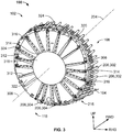
FIG. 3 is a perspective view of thepressure bulkhead apparatus 102 ofFIGS. 1 and2 . Thepressure bulkhead apparatus 102 of the illustrated example may implement theaft pressure bulkhead 110 and/or the forward pressure bulkhead 114 ofFIG. 1 . Thepressure bulkhead apparatus 102 of the illustrated example couples to a frame of the fuselage 104 (e.g., stringers, formers, frames (e.g., theframes 202 ofFIG. 2 )). Additionally, thepressure bulkhead apparatus 102 of the illustrated example couples to forward stringers 302 (e.g., thestringers 206 positioned in the internal pressure region 108) and aft stringers 304 (e.g., thestringers 206 positioned in the external pressure region 118). When thepressure bulkhead apparatus 102 is coupled to thefuselage 104, a longitudinal axis 306 (e.g., a central axis) of thepressure bulkhead apparatus 102 aligns (e.g., coaxially aligns) with thelongitudinal axis 204 of thefuselage 104. Thelongitudinal axis 306 is also the longitudinal axis of theframe 308. Portions of the aft stringers 304 and theskin 208 are omitted fromFIG. 3 for clarity. - The
pressure bulkhead apparatus 102 of the illustrated example couples to a frame 308 (e.g., a chord, a ring, an annular plate, theframe 202, etc.) having a radius. The radius of theframe 308 of the illustrated example is similar to a radius of thefuselage 104. Theframe 308 of the illustrated example includes a plurality of beams 312 (e.g., 20 beams) radially spaced relative to alongitudinal axis 306 of thepressure bulkhead apparatus 102 and theframe 308. In some examples, thebeams 312 are radially spaced at equidistant angles or intervals. In some examples, thebeams 312 are radially spaced at different or varying distances, angles or intervals relative to thelongitudinal axis 306. Each of thebeams 312 has afirst end 314 adjacent thelongitudinal axis 306 and asecond end 316 adjacent theframe 308. To support the respective first ends 314 of thebeams 312, thepressure bulkhead apparatus 102 includes ahub assembly 318 coaxially aligned with thelongitudinal axis 306. The first ends 314 of thebeams 312 are coupled to thehub assembly 318. The respective second ends 316 of thebeams 312 project from thehub assembly 318 toward theframe 308. - The
pressure bulkhead apparatus 102 includes aweb 320 coupled to thebeams 312. In particular, theweb 320 of the illustrated example is a substantially planar skin (e.g., a sheet-shaped member) that is concentrically aligned with thehub assembly 318. Further, thebeams 312 of the illustrated example are positioned against theweb 320. Additionally, thebeams 312 of the illustrated example are each aligned relative to a radius of theweb 320. The respective first ends 314 of thebeams 312 are radially inward of thehub assembly 318 and the respective second ends 316 of thebeams 312 are radially outward relative to a circumference of theweb 320. Theweb 320 of the illustrated example carries pressure loads and/or other non-pressure loads exerted on the pressure bulkhead apparatus 102 (e.g., due to a pressure differential across the pressure bulkhead apparatus 102). - To couple the
frame 308 to thefuselage 104, each of thebeams 312 of thepressure bulkhead apparatus 102 of the illustrated example includes abeam end assembly 324. As described in greater detail below, thebeam end assembly 324 directly couples thebeams 312 to respective aft stringers 304. Additionally, to eliminate moment loads at theinterface 216, thebeam end assembly 324 permits rotation of therespective beams 312 relative the aft stringers 304. Thebeam end assembly 324 prevents translational motion of thebeams 312 relative to the aft stringers 304 (e.g., in the aft-fore direction along thelongitudinal axis 204 of the fuselage). In operation, when a pressure differential is experienced across thepressure bulkhead apparatus 102, theweb 320 transfers loads to the stringers 206 (e.g., the aft stringers 304 and/or forward stringers 302) via thebeams 312 and thebeam end assembly 324 of each of thebeams 312. -
FIG. 4 is an enlarged, partial view of thepressure bulkhead apparatus 102 ofFIGS. 1-3 . Theframe 308 of thepressure bulkhead apparatus 102 is partially shown and theweb 320 is omitted inFIG. 4 for clarity. As shown inFIG. 4 , abeam 404 of the plurality ofbeams 312 includes abody 406 having alongitudinal axis 408 between thefirst end 314 of thebeam 404 and thesecond end 316 of thebeam 404 opposite thefirst end 314. Thehub assembly 318 of the illustrated example includes ahub 402 and acenter cap 403. Thefirst end 314 of thebeam 404 is coupled to thehub 402. In some examples, thehub 402 may include an annular channel or slot to receive the first ends 314 of thebeams 312. Thebeams 312 may be positioned against a surface 322 (FIG. 3 ) of theweb 320. Thesecond end 316 of thebeam 404 projects from thehub 402 in a direction toward theframe 308. - The
second end 316 of thebeam 404 is coupled to theframe 308 via thebeam end assembly 324. In particular, thebeam 404 is substantially coplanar with anaft stringer 410 of the plurality of aft stringers 304 and/or aforward stringer 412 of the plurality of forward stringers 302. Thus, thebeam end assembly 324 of the illustrated example couples thesecond end 316 of thebeam 404 to theaft stringer 410 that is adjacent to thebeam 404. In this manner, when thebeam 404 is coupled to theaft stringer 410, thelongitudinal axis 408 of thebeam 404, alongitudinal axis 414 of thebeam end assembly 324, and alongitudinal axis 416 of theaft stringer 410 are substantially coplanar. In some instances, a plane taken along thelongitudinal axis 408 of thebeam 404 and/or thelongitudinal axis 414 of thebeam end assembly 324 bifurcates thelongitudinal axis 416 of theaft stringer 410. Thebeam end assembly 324 directsloads 418 from thepressure bulkhead apparatus 102 and/or thebeam 404 along a length of theaft stringer 410, theforward stringer 412, and theskin 208 in a fore-aft direction (e.g., a tension load). Additionally, theframe 308 is coupled to theforward stringer 412 via a brace or bracket 420 (e.g., an angled bracket). Theloads 418 may be transferred to theforward stringer 412 via thebracket 420 and thebeam end assembly 324. -
FIG. 5 is a partial, enlarged view of theexample bulkhead apparatus 102 ofFIGS. 1-4 . Thebeam end assembly 324 of the illustrated example includes a first fitting 504 (e.g., a beam end fitting) and a second fitting 506 (e.g., an aft end fitting) that are coupled via alinkage assembly 502. More specifically, thelinkage assembly 502 is pivotally coupled to at least one of thefirst fitting 504 or thesecond fitting 506. Thelinkage assembly 502 of the illustrated example includes alink 508, a first pin and bearing assembly 602 (FIG. 6 ) (e.g., a fastener and bearing assembly, a bolt and spherical bearing assembly, a bushing, etc.), and a second pin and bearing assembly 604 (FIG. 6 ) (e.g., a fastener and bearing assembly, a bolt and spherical bearing assembly, a bushing, etc.). The first pin and bearingassembly 602 and the second pin and bearingassembly 604 are not shown inFIG. 5 for clarity. Thelink 508 of the illustrated example includes a first opening 521 adjacent afirst end 518 and asecond opening 523 adjacent asecond end 534. - The
first fitting 504 of the illustrated example is coupled (e.g., fixed) to thesecond end 316 of thebeam 404. Thefirst fitting 504 of the illustrated example includes abody 510 and aclevis 512 coupled to thebody 510. Thefirst fitting 504 couples to thesecond end 316 of thebeam 404 via, for example, fasteners 514 (e.g., bolts, screws, rivets, etc.). Theclevis 512 defines aslot 516 to receive thefirst end 518 of thelink 508 and anopening 520. Theopening 520 aligns (e.g., coaxially aligns) with the opening 521 of thefirst end 518 of thelink 508 to receive the first pin and bearing assembly 602 (FIG. 6 ) to pivotally couple thefirst end 518 of thelink 508 and theclevis 512 of thefirst fitting 504. - The
second fitting 506 of the illustrated example is coupled (e.g., fixed) to theframe 308. Additionally, thesecond fitting 506 of the illustrated example is coupled (e.g., fixed) to theaft stringer 410. Thesecond fitting 506 of the illustrated example includes a first portion 524 and a second portion 526. The first portion 524 of the illustrated example is aflange 528 and the second portion 526 is a clevis 530. The clevis 530 defines aslot 532 to receive thesecond end 534 of thelink 508 and anopening 536. Theopening 536 of the clevis 530 aligns (e.g., coaxially aligns) with theopening 523 of thelink 508 to receive the second pin and bearing assembly 604 (FIG. 6 ) to pivotally couple thesecond end 534 of thelink 508 and thesecond fitting 506. - The
second fitting 506 of the illustrated example also includes a third portion 538 defining anarm 540 to couple thesecond fitting 506 to theaft stringer 410. More specifically, thearm 540 of the illustrated example protrudes from the clevis 530 of thesecond fitting 506 to enable at least a portion of thearm 540 to be positioned within a receivingchannel 542 of theaft stringer 410. Thearm 540 of thesecond fitting 506 of the illustrated example is coupled to theaft stringer 410 via fasteners (e.g., bolts, screws, rivets, etc.) throughopenings 544 of theaft stringer 410. Thus, in the illustrated example, thefirst fitting 504 is fixed to thesecond end 316 of thebeam 404, thesecond fitting 506 is fixed to theaft stringer 410 via thearm 540 and theframe 308 via theflange 528, and thelink 508 is pivotally coupled to thefirst fitting 504 and thesecond fitting 506. -
FIG. 6 is another enlarged, partial view of the examplepressure bulkhead apparatus 102 ofFIGS. 1-5 . When assembled, thefirst fitting 504, thesecond fitting 506, and link 508 transfer theloads 418 from thebeam 404 to theaft stringer 410 in a direction along a longitudinal length (e.g., along the longitudinal axis 416) of the aft stringer 410 (e.g., a fore-aft direction 612). In some examples, thelongitudinal axis 408 of thebeam 404 and thelongitudinal axis 416 of theaft stringer 410 are coplanar. In some examples, alongitudinal axis 605 of thefirst fitting 504 is aligned with (e.g., in substantially the same plane as) thelongitudinal axis 408 of theaft stringer 410. In some examples, thefirst fitting 504 may be integrally formed with thesecond end 316 of thebeam 404 and/or may be coupled to thesecond end 316 of the beam 404 (e.g., via a clevis connection) such that thelongitudinal axis 605 of thefirst fitting 504 is aligned with (e.g., in substantially the same plane as) thelongitudinal axis 408 of thebeam 404. In the illustrated example, theframe 308 and thebeams 312 are fixed relative to theaft stringer 410 and/or the forward stringer 412 (i.e., the fuselage 104) in the fore-aft direction 612. In other words, thebeam 404 cannot translate or rotate relative to theframe 308 and/or thestringers 206. However, the beam end assembly 324 (e.g., via thelink 508 and the first and second pin and the bearingassemblies respective openings 521 and 523 of the link 508) may prevent apotential moment load 610 between thesecond end 316 of thebeam 404 and theaft stringer 410 and/or theforward stringer 412. - During flight, a pressure differential across the
pressure bulkhead apparatus 102 between theexternal pressure region 118 and theinternal pressure region 108 and/or other loads (e.g., contraction and expansion loads) will cause thebeam 404 to deflect (e.g., at a center or middle portion of the beam 404). The first fitting 504 (e.g., the beam end fitting) pivots about apivot axis 606, and thesecond end 534 of thelink 508 pivots about apivot axis 608 and thereby prevents the transfer of thepotential moment load 610 to theaft stringer 410, theforward stringer 412 and theframe 308. However, thebeam end assembly 324 provides a load path for tension loads from thefirst fitting 504 to thesecond fitting 506. Thebeams 312, the beam end assembly 324 (e.g., thefirst fitting 504, thesecond fitting 506, thelink 508, the first and second pin and bearingassemblies web 320, and/or theframe 308 of thebulkhead apparatus 102 of the illustrated example may be composed of steel, aluminum, titanium, carbon reinforced composite material(s), alloy(s), any combination thereof, and/or any other material(s). - From the foregoing, it will be appreciated that the
bulkhead apparatus 102 of the illustrated example may employ beams positioned or oriented in a grid-pattern or orientation. For example, a first plurality of beams may be positioned in a horizontal orientation relative to a longitudinal axis of the bulkhead apparatus and a second plurality of beams may be positioned in a vertical orientation. In some such examples, thebeam end assembly 324 may be employed to directly couple the beams of a bulkhead apparatus in a grid-pattern (e.g., the first and second plurality of beams) directly torespective stringers 208 of thefuselage 104 in substantially the same manner as disclosed herein. The example bulkhead apparatus disclosed herein simplifies manufacturing by reducing the number of components (e.g., by approximately half) needed to couple known bulkhead apparatus to a fuselage of an aircraft. - At least some of the aforementioned examples include one or more features and/or benefits including, but not limited to, the following:
- In some examples, a pressure bulkhead apparatus includes a frame and a plurality of beams radially spaced relative to a longitudinal axis of the frame. A beam from the plurality of beams has a first end and a second end. In some such examples, a beam end assembly couples the second end of the beam and a stringer of a fuselage. In some examples, the beam end assembly enables the second end of the beam to move relative to at least one of the frame or the stringer.
- In some examples, the beam end assembly enables the second end of the beam to rotate relative to the at least one of the frame or the stringer.
- In some examples, the beam end assembly includes a first fitting, a second fitting and a linkage assembly.
- In some examples, the first fitting is coupled to the second end of the beam.
- In some examples, the second fitting is coupled to the stringer.
- In some examples the linkage assembly is pivotally coupled to the first fitting and the second fitting.
- In some examples, the linage assembly includes a link, a first pin and bearing assembly, and a second pin and bearing assembly.
- In some examples, the link has a first opening adjacent a first end of the link to receive the first pin and bearing assembly to pivotally couple the link and the first fitting, and the link has a second opening adjacent a second end of the link to receive the second pin and bearing assembly to pivotally couple the link and the second fitting.
- In some examples, a web is coupled to the beams.
- In some examples, the beam end assembly is configured to transfer a load to the stringer such that the load is aligned along a longitudinal axis of the stringer.
- In some examples, a hub is coaxially aligned with the longitudinal axis of the frame, where the first end of the beam is configured to couple to the hub.
- In some examples, the beam is coplanar with the stringer.
- In some examples, an aircraft includes a fuselage having stringers aligned along a length of the fuselage and a bulkhead coupled to the fuselage. In some such examples, the bulkhead has a web and beams. In some such examples, the beams are radially spaced relative to a longitudinal axis of the web. In some examples, each beam includes a first end and an opposing second end. In some such examples, the first end is radially inward adjacent a center of the web and the second end is radially outward adjacent a circumference of the web. In some such examples, a respective beam end assembly pivotally couples the second end of each beam and a respective one of the stringers. In some examples, the beam end assemblies are configured to eliminate moment loading at an interface between the beams and the stringers.
- In some examples, a hub is concentrically aligned relative to the web.
- In some examples, the first end of each beam is coupled to the hub.
- In some examples, the beam end assembly is pivotally coupled to the respective ones of the stringers.
- In some examples, a bulkhead includes a hub and a beam having a first end and a second end opposite the first end. In some such examples, the first end is directly coupled to the hub and the second end is radially outward relative to a frame. In some such examples, a first fitting is coupled to the second end of the beam. In some such examples, a second fitting has a first portion and a second portion, where the first portion is coupled to the frame and the second portion is configured to couple to a stringer of a fuselage. In some such examples, a linkage assembly pivotally couples to at least one of the first fitting or second fitting.
- In some examples, the second fitting includes a body defining the first portion and the second portion.
- In some examples, the first portion is a flange and the second portion is a clevis.
- In some examples, the second fitting includes a third portion defining an arm configured to couple to the stringer.
- In some examples, the first fitting, the second fitting and the linkage assembly transfer a load to the stringer in a direction along a longitudinal length of the stringer.
- In some examples, the first fitting, the second fitting and the linkage assembly eliminate a moment load between the second end of the beam and the stringer.
- According to a first arrangement, there is provided a bulkhead apparatus comprising: a frame; a plurality of beams radially spaced relative to a longitudinal axis of the frame, a beam from the plurality of beams having a first end and a second end; and a beam end assembly to couple the second end of the beam and a stringer of a fuselage, the beam end assembly to enable the second end of the beam to move relative to at least one of the frame or the stringer.
- Optionally, the beam end assembly is configured to enable the second end of the beam to rotate relative to the at least one of the frame or the stringer.
- Optionally, the beam end assembly includes a first fitting, a second fitting, and a linkage assembly.
- Optionally, the first fitting is coupled to the second end of the beam.
- Optionally, the second fitting is coupled to the stringer.
- Optionally, the linkage assembly is pivotally coupled to the first fitting and the second fitting.
- Optionally, the linkage assembly includes a link, a first pin and bearing assembly, and a second pin and bearing assembly.
- Optionally, the link has a first opening adjacent a first end of the link to receive the first pin and bearing assembly to pivotally couple the link and the first fitting, and the link has a second opening adjacent a second end of the link to receive the second pin and bearing assembly to pivotally couple the link and the second fitting.
- Optionally, the apparatus further comprises a web coupled to the beams.
- Optionally, the beam end assembly is configured to transfer a load to the stringer such that the load is aligned along a longitudinal axis of the stringer.
- Optionally, the apparatus further comprising a hub coaxially aligned with the longitudinal axis of the frame, wherein the first end of the beam is configured to couple to the hub.
- Optionally, the beam is coplanar with the stringer.
- According to a second arrangement, there is provided an aircraft comprising a fuselage having stringers aligned along a length of the fuselage; and the bulkhead apparatus of the first arrangement.
- According to a third arrangement, there is provided a method for assembling the bulkhead apparatus of the first arrangement.
- According to a fourth arrangement, there is provided an aircraft comprising: a fuselage having stringers aligned along a length of the fuselage; a bulkhead coupled to the fuselage, the bulkhead having a web and beams, the beams radially spaced relative to a longitudinal axis of the web, each beam including a first end and an opposing second end, the first end being radially inward adjacent a center of the web, the second end being radially outward adjacent a circumference of the web; and a respective beam end assembly to pivotally couple the second end of each beam and a respective one of the stringers, the beam end assemblies are configured to eliminate moment loading at an interface between the beams and the stringers.
- Optionally, the aircraft further comprises a hub concentrically aligned relative to the web, wherein the first end of each beam is coupled to the hub.
- Optionally, each link is pivotally coupled to the respective ones of the stringers.
- According to a fifth arrangement, there is provided a bulkhead comprising: a hub; a beam having a first end and a second end opposite the first end, the first end coupled to the hub, the second end being radially outward relative to a frame; a first fitting coupled to the second end of the beam; a second fitting having a first portion and a second portion, the first portion coupled to the frame and the second portion to couple to a stringer of a fuselage; and a linkage assembly pivotally coupled to at least one of the first fitting or second fitting.
- Optionally, the second fitting of the first or fifth arrangement includes a body defining the first portion and the second portion.
- Optionally, the first portion is a flange and the second portion is a clevis.
- Optionally, the second fitting includes a third portion defining an arm configured to couple to the stringer.
- Optionally, the first fitting, the second fitting, and the linkage assembly transfer a load to the stringer in a direction along a longitudinal length of the stringer.
- Optionally, the first fitting, the second fitting, and the linkage assembly are configured to eliminate a moment load between the second end of the beam and the stringer.
- According to a sixth arrangement, there is provided an aircraft comprising a fuselage having stringers aligned along a length of the fuselage; and the bulkhead of the fifth arrangement.
- According to a seventh arrangement, there is provided a method for assembling the bulkhead of the fifth arrangement.
- Although certain example apparatus and methods have been described herein, the scope of coverage of this patent is not limited thereto. On the contrary, this patent covers all methods, apparatus and articles of manufacture fairly falling within the scope of the amended claims either literally or under doctrine of equivalents.
Claims (15)
- A bulkhead apparatus (102) comprising:a frame (202, 308);a plurality of beams (312) radially spaced relative to a longitudinal axis (306) of the frame, a beam (312, 404) from the plurality of beams having a first end (314) and a second end (316); anda beam end assembly (324) to couple the second end of the beam and a respective stringer (206, 302, 304, 410, 412) of a fuselage (104), the beam end assembly to enable the second end of the beam to move relative to at least one of the frame or the respective stringer.
- The apparatus (102) of claim 1, wherein the beam end assembly (324) is configured to enable the second end (316) of the beam (312) to rotate relative to the at least one of the frame (202) or the respective stringer (206).
- The apparatus (102) of claim 1 or 2, wherein the beam end assembly (324) includes a first fitting (504), a second fitting (506), and a linkage assembly (502), optionally wherein the first fitting, the second fitting, and the linkage assembly are configured to eliminate a moment load (610) between the second end (316) of the beam (404) and the respective stringer (206, 410, 412).
- The apparatus (102) of claim 3, wherein the first fitting (504) is coupled to the second end (316) of the beam (312) and the second fitting (506) is coupled to the respective stringer (206).
- The apparatus (102) of any one of claims 3 to 4, wherein the linkage assembly (502) is pivotally coupled to the first fitting (504) and the second fitting (506).
- The apparatus (102) of any one of claims 3 to 5, wherein the linkage assembly (502) includes a link (508), a first pin and bearing assembly (602), and a second pin and bearing assembly (604).
- The apparatus (102) of claim 6, wherein the link (508) has a first opening (521) adjacent a first end (518) of the link to receive the first pin and bearing assembly (602) to pivotally couple the link and the first fitting (504), and the link has a second opening (523) adjacent a second end (534) of the link to receive the second pin and bearing assembly (604) to pivotally couple the link and the second fitting (506).
- The apparatus (102) of any one of claims 1 to 7, further comprising a web (320) coupled to the beams (312).
- The apparatus (102) of any one of claims 1 to 8, wherein the beam end assembly (324) is configured to transfer a load (418) to the respective stringer (206, 410) such that the load is aligned along a longitudinal axis (416) of the respective stringer.
- The apparatus (102) of any one of claims 1 to 9, further comprising a hub (402) coaxially aligned with the longitudinal axis (306) of the frame (308), wherein the first end (314) of the beam (404) is configured to couple to the hub.
- An aircraft (100) comprising:a fuselage (104) having the stringers (206, 302, 304, 410, 412) aligned along a length of the fuselage;the bulkhead apparatus (102) of any one of claims 1 to 10 coupled to the fuselage, the bulkhead apparatus further comprising a web (320), the plurality of beams (312) radially spaced relative to a longitudinal axis of the web, the first end (314) of each beam being radially inward adjacent a center of the web, the second end (316) of each beam being radially outward adjacent a circumference of the web, whereina respective beam end assembly (324) is pivotally coupled the second end of each beam and the respective stringer, the beam end assemblies are configured to eliminate moment loading at an interface (216) between the beams and the stringers.
- The aircraft (100) of claim 11, further comprising a hub (402) concentrically aligned relative to the web (320), wherein the first end (314) of each beam (312, 404) is coupled to the hub.
- The bulkhead apparatus (102) of any one of claims 3 to 10, wherein the second fitting (506) has a first portion (524) and a second portion (526), the first portion coupled to the frame (308) and the second portion to couple to the respective stringer (410) of the fuselage (104).
- The bulkhead apparatus (102) of claim 13, wherein the second fitting (506) includes a body defining the first portion (524) and the second portion (526), preferably wherein the first portion is a flange (528) and the second portion is a clevis (530).
- The bulkhead apparatus (102) of claim 13 or 14, wherein the second fitting (506) includes a third portion (538) defining an arm (540) configured to couple to the stringer (410).
Applications Claiming Priority (1)
| Application Number | Priority Date | Filing Date | Title |
|---|---|---|---|
| US15/093,226 US10173765B2 (en) | 2016-04-07 | 2016-04-07 | Pressure bulkhead apparatus |
Publications (2)
| Publication Number | Publication Date |
|---|---|
| EP3228534A1 true EP3228534A1 (en) | 2017-10-11 |
| EP3228534B1 EP3228534B1 (en) | 2018-12-26 |
Family
ID=58454949
Family Applications (1)
| Application Number | Title | Priority Date | Filing Date |
|---|---|---|---|
| EP17163535.2A Active EP3228534B1 (en) | 2016-04-07 | 2017-03-29 | Pressure bulkhead apparatus |
Country Status (4)
| Country | Link |
|---|---|
| US (1) | US10173765B2 (en) |
| EP (1) | EP3228534B1 (en) |
| JP (1) | JP6759118B2 (en) |
| CN (1) | CN107264771B (en) |
Families Citing this family (5)
| Publication number | Priority date | Publication date | Assignee | Title |
|---|---|---|---|---|
| FR3072361B1 (en) * | 2017-10-17 | 2019-11-22 | Airbus Operations | LANDING TRAIN CASE ROOF COMPRISING AT LEAST ONE PORTIC INSTALLED AGAINST A LOWER SURFACE OF ITS WALL |
| ES2946516T3 (en) * | 2018-03-02 | 2023-07-20 | Premium Aerotec Gmbh | Pressure bulkhead for an aircraft |
| ES2909500T3 (en) * | 2019-07-30 | 2022-05-06 | Airbus Sas | pressure bulkhead |
| US11420718B2 (en) * | 2020-03-27 | 2022-08-23 | The Boeing Company | Aircraft tail assembly |
| CN115352618B (en) * | 2022-09-02 | 2024-09-13 | 中航通飞华南飞机工业有限公司 | Method for arranging structure of boost cabin with special-shaped cross section |
Citations (2)
| Publication number | Priority date | Publication date | Assignee | Title |
|---|---|---|---|---|
| US5899412A (en) * | 1997-12-19 | 1999-05-04 | Northrop Grumman Corporation | Aircraft pressure containment assembly module |
| US20110290940A1 (en) * | 2010-04-30 | 2011-12-01 | Airbus Operations Gmbh | Pressure bulkhead for purposes of arrangement in an aircraft fuselage |
Family Cites Families (16)
| Publication number | Priority date | Publication date | Assignee | Title |
|---|---|---|---|---|
| US6010286A (en) * | 1997-03-13 | 2000-01-04 | Mcdonald Douglas Corporation | Apparatus for rigidly retaining cargo |
| US6213426B1 (en) * | 1999-07-09 | 2001-04-10 | The Boeing Company | Monolithic structure with redundant load paths |
| JP3997047B2 (en) * | 2000-05-01 | 2007-10-24 | 本田技研工業株式会社 | Bonding structure of skin and pressure bulkhead |
| FR2906524B1 (en) * | 2006-09-28 | 2008-10-31 | Airbus France Sas | AIRCRAFT RADAR CHAMBER SEPARATION PANEL AND FRONT TRAIN BOX |
| DE102007044388B4 (en) * | 2007-09-18 | 2012-08-02 | Airbus Operations Gmbh | Pressure bulkhead and method for dividing an aircraft or spacecraft |
| DE102007052140B4 (en) * | 2007-10-31 | 2012-10-25 | Airbus Operations Gmbh | Structure, in particular hull structure of an aircraft or spacecraft |
| EP2259965B1 (en) * | 2008-03-31 | 2013-01-09 | Honda Patents & Technologies North America, LLC | Pressure bulkhead for aircraft |
| DE102008040213B4 (en) | 2008-07-07 | 2011-08-25 | Airbus Operations GmbH, 21129 | Method for mounting a dome-shaped pressure bulkhead in a tail section of an aircraft, and device for carrying out the method |
| ES2347122B1 (en) * | 2009-03-31 | 2011-08-11 | Airbus Operations, S.L. | ASSEMBLY STRUCTURE OF THE PRESSURE SOCKET OF AN AIRCRAFT. |
| FR2945027B1 (en) * | 2009-04-30 | 2012-11-30 | Airbus France | STOPPING ARMOR FOR AIRCRAFT AND METHOD FOR INSTALLING SUCH A CLOSING |
| DE102009049007A1 (en) * | 2009-10-09 | 2011-04-21 | Airbus Operations Gmbh | Pressure hull of an airplane with rear-side pressure calotte |
| FR2953158B1 (en) * | 2009-11-30 | 2012-01-20 | Airbus Operations Sas | METHOD FOR REALIZING SEAL JUNCTION BETWEEN AIRCRAFT PARTS |
| FR2953193B1 (en) * | 2009-11-30 | 2012-03-16 | Airbus Operations Sas | AIRCRAFT COMPRISING AN INTERNAL ROOFING |
| FR2979896A1 (en) * | 2011-09-08 | 2013-03-15 | Airbus Operations Sas | AIRCRAFT FUSELAGE FRAME ELEMENT |
| FR2983826B1 (en) * | 2011-12-12 | 2013-12-20 | Airbus Operations Sas | FRONT STRUCTURE IMPROVED WITH COMPARTMENT FOR LANDING TRAIN. |
| US10189578B2 (en) * | 2013-06-12 | 2019-01-29 | The Boeing Company | Self-balancing pressure bulkhead |
-
2016
- 2016-04-07 US US15/093,226 patent/US10173765B2/en active Active
-
2017
- 2017-01-30 JP JP2017014325A patent/JP6759118B2/en active Active
- 2017-03-29 EP EP17163535.2A patent/EP3228534B1/en active Active
- 2017-03-31 CN CN201710205386.3A patent/CN107264771B/en active Active
Patent Citations (2)
| Publication number | Priority date | Publication date | Assignee | Title |
|---|---|---|---|---|
| US5899412A (en) * | 1997-12-19 | 1999-05-04 | Northrop Grumman Corporation | Aircraft pressure containment assembly module |
| US20110290940A1 (en) * | 2010-04-30 | 2011-12-01 | Airbus Operations Gmbh | Pressure bulkhead for purposes of arrangement in an aircraft fuselage |
Also Published As
| Publication number | Publication date |
|---|---|
| US20170291678A1 (en) | 2017-10-12 |
| CN107264771A (en) | 2017-10-20 |
| EP3228534B1 (en) | 2018-12-26 |
| JP6759118B2 (en) | 2020-09-23 |
| CN107264771B (en) | 2022-06-07 |
| JP2017206225A (en) | 2017-11-24 |
| US10173765B2 (en) | 2019-01-08 |
Similar Documents
| Publication | Publication Date | Title |
|---|---|---|
| EP3228534B1 (en) | Pressure bulkhead apparatus | |
| US9308988B2 (en) | Aircraft main landing gear and method of operating the same | |
| JP6784523B2 (en) | Pinned fuselage and wing connection | |
| JP7804468B2 (en) | Connector for connecting the center wing box of an aircraft to the bulkhead | |
| US9669939B2 (en) | Aircraft supplemental thrust device and method of operating the same | |
| US20210107618A1 (en) | Single Butt Line Keel and Roof Beam | |
| EP3725677B1 (en) | Aircraft landing gear forward trunnion support assemblies and related methods | |
| US9446835B2 (en) | Aircraft wing | |
| US20250276780A1 (en) | Wing-Fuselage Joint |
Legal Events
| Date | Code | Title | Description |
|---|---|---|---|
| PUAI | Public reference made under article 153(3) epc to a published international application that has entered the european phase |
Free format text: ORIGINAL CODE: 0009012 |
|
| STAA | Information on the status of an ep patent application or granted ep patent |
Free format text: STATUS: REQUEST FOR EXAMINATION WAS MADE |
|
| 17P | Request for examination filed |
Effective date: 20170329 |
|
| AK | Designated contracting states |
Kind code of ref document: A1 Designated state(s): AL AT BE BG CH CY CZ DE DK EE ES FI FR GB GR HR HU IE IS IT LI LT LU LV MC MK MT NL NO PL PT RO RS SE SI SK SM TR |
|
| AX | Request for extension of the european patent |
Extension state: BA ME |
|
| GRAP | Despatch of communication of intention to grant a patent |
Free format text: ORIGINAL CODE: EPIDOSNIGR1 |
|
| STAA | Information on the status of an ep patent application or granted ep patent |
Free format text: STATUS: GRANT OF PATENT IS INTENDED |
|
| INTG | Intention to grant announced |
Effective date: 20180613 |
|
| GRAS | Grant fee paid |
Free format text: ORIGINAL CODE: EPIDOSNIGR3 |
|
| GRAJ | Information related to disapproval of communication of intention to grant by the applicant or resumption of examination proceedings by the epo deleted |
Free format text: ORIGINAL CODE: EPIDOSDIGR1 |
|
| GRAL | Information related to payment of fee for publishing/printing deleted |
Free format text: ORIGINAL CODE: EPIDOSDIGR3 |
|
| STAA | Information on the status of an ep patent application or granted ep patent |
Free format text: STATUS: REQUEST FOR EXAMINATION WAS MADE |
|
| GRAR | Information related to intention to grant a patent recorded |
Free format text: ORIGINAL CODE: EPIDOSNIGR71 |
|
| STAA | Information on the status of an ep patent application or granted ep patent |
Free format text: STATUS: GRANT OF PATENT IS INTENDED |
|
| GRAA | (expected) grant |
Free format text: ORIGINAL CODE: 0009210 |
|
| STAA | Information on the status of an ep patent application or granted ep patent |
Free format text: STATUS: THE PATENT HAS BEEN GRANTED |
|
| INTC | Intention to grant announced (deleted) | ||
| INTG | Intention to grant announced |
Effective date: 20181114 |
|
| AK | Designated contracting states |
Kind code of ref document: B1 Designated state(s): AL AT BE BG CH CY CZ DE DK EE ES FI FR GB GR HR HU IE IS IT LI LT LU LV MC MK MT NL NO PL PT RO RS SE SI SK SM TR |
|
| REG | Reference to a national code |
Ref country code: GB Ref legal event code: FG4D |
|
| REG | Reference to a national code |
Ref country code: CH Ref legal event code: EP |
|
| REG | Reference to a national code |
Ref country code: AT Ref legal event code: REF Ref document number: 1081038 Country of ref document: AT Kind code of ref document: T Effective date: 20190115 |
|
| REG | Reference to a national code |
Ref country code: DE Ref legal event code: R096 Ref document number: 602017001522 Country of ref document: DE |
|
| REG | Reference to a national code |
Ref country code: IE Ref legal event code: FG4D |
|
| PG25 | Lapsed in a contracting state [announced via postgrant information from national office to epo] |
Ref country code: LV Free format text: LAPSE BECAUSE OF FAILURE TO SUBMIT A TRANSLATION OF THE DESCRIPTION OR TO PAY THE FEE WITHIN THE PRESCRIBED TIME-LIMIT Effective date: 20181226 Ref country code: LT Free format text: LAPSE BECAUSE OF FAILURE TO SUBMIT A TRANSLATION OF THE DESCRIPTION OR TO PAY THE FEE WITHIN THE PRESCRIBED TIME-LIMIT Effective date: 20181226 Ref country code: NO Free format text: LAPSE BECAUSE OF FAILURE TO SUBMIT A TRANSLATION OF THE DESCRIPTION OR TO PAY THE FEE WITHIN THE PRESCRIBED TIME-LIMIT Effective date: 20190326 Ref country code: FI Free format text: LAPSE BECAUSE OF FAILURE TO SUBMIT A TRANSLATION OF THE DESCRIPTION OR TO PAY THE FEE WITHIN THE PRESCRIBED TIME-LIMIT Effective date: 20181226 Ref country code: BG Free format text: LAPSE BECAUSE OF FAILURE TO SUBMIT A TRANSLATION OF THE DESCRIPTION OR TO PAY THE FEE WITHIN THE PRESCRIBED TIME-LIMIT Effective date: 20190326 Ref country code: HR Free format text: LAPSE BECAUSE OF FAILURE TO SUBMIT A TRANSLATION OF THE DESCRIPTION OR TO PAY THE FEE WITHIN THE PRESCRIBED TIME-LIMIT Effective date: 20181226 |
|
| REG | Reference to a national code |
Ref country code: NL Ref legal event code: MP Effective date: 20181226 |
|
| REG | Reference to a national code |
Ref country code: LT Ref legal event code: MG4D |
|
| PG25 | Lapsed in a contracting state [announced via postgrant information from national office to epo] |
Ref country code: GR Free format text: LAPSE BECAUSE OF FAILURE TO SUBMIT A TRANSLATION OF THE DESCRIPTION OR TO PAY THE FEE WITHIN THE PRESCRIBED TIME-LIMIT Effective date: 20190327 Ref country code: RS Free format text: LAPSE BECAUSE OF FAILURE TO SUBMIT A TRANSLATION OF THE DESCRIPTION OR TO PAY THE FEE WITHIN THE PRESCRIBED TIME-LIMIT Effective date: 20181226 Ref country code: SE Free format text: LAPSE BECAUSE OF FAILURE TO SUBMIT A TRANSLATION OF THE DESCRIPTION OR TO PAY THE FEE WITHIN THE PRESCRIBED TIME-LIMIT Effective date: 20181226 Ref country code: AL Free format text: LAPSE BECAUSE OF FAILURE TO SUBMIT A TRANSLATION OF THE DESCRIPTION OR TO PAY THE FEE WITHIN THE PRESCRIBED TIME-LIMIT Effective date: 20181226 |
|
| REG | Reference to a national code |
Ref country code: AT Ref legal event code: MK05 Ref document number: 1081038 Country of ref document: AT Kind code of ref document: T Effective date: 20181226 |
|
| PG25 | Lapsed in a contracting state [announced via postgrant information from national office to epo] |
Ref country code: NL Free format text: LAPSE BECAUSE OF FAILURE TO SUBMIT A TRANSLATION OF THE DESCRIPTION OR TO PAY THE FEE WITHIN THE PRESCRIBED TIME-LIMIT Effective date: 20181226 |
|
| PG25 | Lapsed in a contracting state [announced via postgrant information from national office to epo] |
Ref country code: ES Free format text: LAPSE BECAUSE OF FAILURE TO SUBMIT A TRANSLATION OF THE DESCRIPTION OR TO PAY THE FEE WITHIN THE PRESCRIBED TIME-LIMIT Effective date: 20181226 Ref country code: PL Free format text: LAPSE BECAUSE OF FAILURE TO SUBMIT A TRANSLATION OF THE DESCRIPTION OR TO PAY THE FEE WITHIN THE PRESCRIBED TIME-LIMIT Effective date: 20181226 Ref country code: IT Free format text: LAPSE BECAUSE OF FAILURE TO SUBMIT A TRANSLATION OF THE DESCRIPTION OR TO PAY THE FEE WITHIN THE PRESCRIBED TIME-LIMIT Effective date: 20181226 Ref country code: CZ Free format text: LAPSE BECAUSE OF FAILURE TO SUBMIT A TRANSLATION OF THE DESCRIPTION OR TO PAY THE FEE WITHIN THE PRESCRIBED TIME-LIMIT Effective date: 20181226 Ref country code: PT Free format text: LAPSE BECAUSE OF FAILURE TO SUBMIT A TRANSLATION OF THE DESCRIPTION OR TO PAY THE FEE WITHIN THE PRESCRIBED TIME-LIMIT Effective date: 20190426 |
|
| PG25 | Lapsed in a contracting state [announced via postgrant information from national office to epo] |
Ref country code: RO Free format text: LAPSE BECAUSE OF FAILURE TO SUBMIT A TRANSLATION OF THE DESCRIPTION OR TO PAY THE FEE WITHIN THE PRESCRIBED TIME-LIMIT Effective date: 20181226 Ref country code: IS Free format text: LAPSE BECAUSE OF FAILURE TO SUBMIT A TRANSLATION OF THE DESCRIPTION OR TO PAY THE FEE WITHIN THE PRESCRIBED TIME-LIMIT Effective date: 20190426 Ref country code: SM Free format text: LAPSE BECAUSE OF FAILURE TO SUBMIT A TRANSLATION OF THE DESCRIPTION OR TO PAY THE FEE WITHIN THE PRESCRIBED TIME-LIMIT Effective date: 20181226 Ref country code: EE Free format text: LAPSE BECAUSE OF FAILURE TO SUBMIT A TRANSLATION OF THE DESCRIPTION OR TO PAY THE FEE WITHIN THE PRESCRIBED TIME-LIMIT Effective date: 20181226 Ref country code: SK Free format text: LAPSE BECAUSE OF FAILURE TO SUBMIT A TRANSLATION OF THE DESCRIPTION OR TO PAY THE FEE WITHIN THE PRESCRIBED TIME-LIMIT Effective date: 20181226 |
|
| REG | Reference to a national code |
Ref country code: DE Ref legal event code: R097 Ref document number: 602017001522 Country of ref document: DE |
|
| PG25 | Lapsed in a contracting state [announced via postgrant information from national office to epo] |
Ref country code: MC Free format text: LAPSE BECAUSE OF FAILURE TO SUBMIT A TRANSLATION OF THE DESCRIPTION OR TO PAY THE FEE WITHIN THE PRESCRIBED TIME-LIMIT Effective date: 20181226 Ref country code: DK Free format text: LAPSE BECAUSE OF FAILURE TO SUBMIT A TRANSLATION OF THE DESCRIPTION OR TO PAY THE FEE WITHIN THE PRESCRIBED TIME-LIMIT Effective date: 20181226 Ref country code: AT Free format text: LAPSE BECAUSE OF FAILURE TO SUBMIT A TRANSLATION OF THE DESCRIPTION OR TO PAY THE FEE WITHIN THE PRESCRIBED TIME-LIMIT Effective date: 20181226 |
|
| PLBE | No opposition filed within time limit |
Free format text: ORIGINAL CODE: 0009261 |
|
| STAA | Information on the status of an ep patent application or granted ep patent |
Free format text: STATUS: NO OPPOSITION FILED WITHIN TIME LIMIT |
|
| PG25 | Lapsed in a contracting state [announced via postgrant information from national office to epo] |
Ref country code: LU Free format text: LAPSE BECAUSE OF NON-PAYMENT OF DUE FEES Effective date: 20190329 |
|
| 26N | No opposition filed |
Effective date: 20190927 |
|
| REG | Reference to a national code |
Ref country code: BE Ref legal event code: MM Effective date: 20190331 |
|
| PG25 | Lapsed in a contracting state [announced via postgrant information from national office to epo] |
Ref country code: IE Free format text: LAPSE BECAUSE OF NON-PAYMENT OF DUE FEES Effective date: 20190329 |
|
| PG25 | Lapsed in a contracting state [announced via postgrant information from national office to epo] |
Ref country code: BE Free format text: LAPSE BECAUSE OF NON-PAYMENT OF DUE FEES Effective date: 20190331 Ref country code: SI Free format text: LAPSE BECAUSE OF FAILURE TO SUBMIT A TRANSLATION OF THE DESCRIPTION OR TO PAY THE FEE WITHIN THE PRESCRIBED TIME-LIMIT Effective date: 20181226 |
|
| PG25 | Lapsed in a contracting state [announced via postgrant information from national office to epo] |
Ref country code: TR Free format text: LAPSE BECAUSE OF FAILURE TO SUBMIT A TRANSLATION OF THE DESCRIPTION OR TO PAY THE FEE WITHIN THE PRESCRIBED TIME-LIMIT Effective date: 20181226 |
|
| PG25 | Lapsed in a contracting state [announced via postgrant information from national office to epo] |
Ref country code: MT Free format text: LAPSE BECAUSE OF NON-PAYMENT OF DUE FEES Effective date: 20190329 |
|
| REG | Reference to a national code |
Ref country code: CH Ref legal event code: PL |
|
| PG25 | Lapsed in a contracting state [announced via postgrant information from national office to epo] |
Ref country code: CH Free format text: LAPSE BECAUSE OF NON-PAYMENT OF DUE FEES Effective date: 20200331 Ref country code: LI Free format text: LAPSE BECAUSE OF NON-PAYMENT OF DUE FEES Effective date: 20200331 |
|
| PG25 | Lapsed in a contracting state [announced via postgrant information from national office to epo] |
Ref country code: CY Free format text: LAPSE BECAUSE OF FAILURE TO SUBMIT A TRANSLATION OF THE DESCRIPTION OR TO PAY THE FEE WITHIN THE PRESCRIBED TIME-LIMIT Effective date: 20181226 |
|
| PG25 | Lapsed in a contracting state [announced via postgrant information from national office to epo] |
Ref country code: HU Free format text: LAPSE BECAUSE OF FAILURE TO SUBMIT A TRANSLATION OF THE DESCRIPTION OR TO PAY THE FEE WITHIN THE PRESCRIBED TIME-LIMIT; INVALID AB INITIO Effective date: 20170329 |
|
| PG25 | Lapsed in a contracting state [announced via postgrant information from national office to epo] |
Ref country code: MK Free format text: LAPSE BECAUSE OF FAILURE TO SUBMIT A TRANSLATION OF THE DESCRIPTION OR TO PAY THE FEE WITHIN THE PRESCRIBED TIME-LIMIT Effective date: 20181226 |
|
| P01 | Opt-out of the competence of the unified patent court (upc) registered |
Effective date: 20230516 |
|
| PGFP | Annual fee paid to national office [announced via postgrant information from national office to epo] |
Ref country code: GB Payment date: 20260327 Year of fee payment: 10 |
|
| PGFP | Annual fee paid to national office [announced via postgrant information from national office to epo] |
Ref country code: DE Payment date: 20260327 Year of fee payment: 10 |
|
| PGFP | Annual fee paid to national office [announced via postgrant information from national office to epo] |
Ref country code: FR Payment date: 20260325 Year of fee payment: 10 |