EP3228406A1 - Method of manufacture of a component - Google Patents
Method of manufacture of a component Download PDFInfo
- Publication number
- EP3228406A1 EP3228406A1 EP17160056.2A EP17160056A EP3228406A1 EP 3228406 A1 EP3228406 A1 EP 3228406A1 EP 17160056 A EP17160056 A EP 17160056A EP 3228406 A1 EP3228406 A1 EP 3228406A1
- Authority
- EP
- European Patent Office
- Prior art keywords
- component
- dimensions
- finishing operation
- product
- heat treatment
- Prior art date
- Legal status (The legal status is an assumption and is not a legal conclusion. Google has not performed a legal analysis and makes no representation as to the accuracy of the status listed.)
- Withdrawn
Links
Images


Classifications
-
- B—PERFORMING OPERATIONS; TRANSPORTING
- B22—CASTING; POWDER METALLURGY
- B22F—WORKING METALLIC POWDER; MANUFACTURE OF ARTICLES FROM METALLIC POWDER; MAKING METALLIC POWDER; APPARATUS OR DEVICES SPECIALLY ADAPTED FOR METALLIC POWDER
- B22F3/00—Manufacture of workpieces or articles from metallic powder characterised by the manner of compacting or sintering; Apparatus specially adapted therefor ; Presses and furnaces
- B22F3/24—After-treatment of workpieces or articles
-
- B—PERFORMING OPERATIONS; TRANSPORTING
- B22—CASTING; POWDER METALLURGY
- B22F—WORKING METALLIC POWDER; MANUFACTURE OF ARTICLES FROM METALLIC POWDER; MAKING METALLIC POWDER; APPARATUS OR DEVICES SPECIALLY ADAPTED FOR METALLIC POWDER
- B22F10/00—Additive manufacturing of workpieces or articles from metallic powder
- B22F10/60—Treatment of workpieces or articles after build-up
- B22F10/62—Treatment of workpieces or articles after build-up by chemical means
-
- B—PERFORMING OPERATIONS; TRANSPORTING
- B22—CASTING; POWDER METALLURGY
- B22F—WORKING METALLIC POWDER; MANUFACTURE OF ARTICLES FROM METALLIC POWDER; MAKING METALLIC POWDER; APPARATUS OR DEVICES SPECIALLY ADAPTED FOR METALLIC POWDER
- B22F10/00—Additive manufacturing of workpieces or articles from metallic powder
- B22F10/60—Treatment of workpieces or articles after build-up
- B22F10/64—Treatment of workpieces or articles after build-up by thermal means
-
- B—PERFORMING OPERATIONS; TRANSPORTING
- B22—CASTING; POWDER METALLURGY
- B22F—WORKING METALLIC POWDER; MANUFACTURE OF ARTICLES FROM METALLIC POWDER; MAKING METALLIC POWDER; APPARATUS OR DEVICES SPECIALLY ADAPTED FOR METALLIC POWDER
- B22F10/00—Additive manufacturing of workpieces or articles from metallic powder
- B22F10/60—Treatment of workpieces or articles after build-up
- B22F10/66—Treatment of workpieces or articles after build-up by mechanical means
-
- B—PERFORMING OPERATIONS; TRANSPORTING
- B29—WORKING OF PLASTICS; WORKING OF SUBSTANCES IN A PLASTIC STATE IN GENERAL
- B29C—SHAPING OR JOINING OF PLASTICS; SHAPING OF MATERIAL IN A PLASTIC STATE, NOT OTHERWISE PROVIDED FOR; AFTER-TREATMENT OF THE SHAPED PRODUCTS, e.g. REPAIRING
- B29C64/00—Additive manufacturing, i.e. manufacturing of three-dimensional [3D] objects by additive deposition, additive agglomeration or additive layering, e.g. by 3D printing, stereolithography or selective laser sintering
- B29C64/10—Processes of additive manufacturing
- B29C64/141—Processes of additive manufacturing using only solid materials
- B29C64/153—Processes of additive manufacturing using only solid materials using layers of powder being selectively joined, e.g. by selective laser sintering or melting
-
- B—PERFORMING OPERATIONS; TRANSPORTING
- B33—ADDITIVE MANUFACTURING TECHNOLOGY
- B33Y—ADDITIVE MANUFACTURING, i.e. MANUFACTURING OF THREE-DIMENSIONAL [3D] OBJECTS BY ADDITIVE DEPOSITION, ADDITIVE AGGLOMERATION OR ADDITIVE LAYERING, e.g. BY 3D PRINTING, STEREOLITHOGRAPHY OR SELECTIVE LASER SINTERING
- B33Y10/00—Processes of additive manufacturing
-
- B—PERFORMING OPERATIONS; TRANSPORTING
- B33—ADDITIVE MANUFACTURING TECHNOLOGY
- B33Y—ADDITIVE MANUFACTURING, i.e. MANUFACTURING OF THREE-DIMENSIONAL [3D] OBJECTS BY ADDITIVE DEPOSITION, ADDITIVE AGGLOMERATION OR ADDITIVE LAYERING, e.g. BY 3D PRINTING, STEREOLITHOGRAPHY OR SELECTIVE LASER SINTERING
- B33Y80/00—Products made by additive manufacturing
-
- C—CHEMISTRY; METALLURGY
- C04—CEMENTS; CONCRETE; ARTIFICIAL STONE; CERAMICS; REFRACTORIES
- C04B—LIME, MAGNESIA; SLAG; CEMENTS; COMPOSITIONS THEREOF, e.g. MORTARS, CONCRETE OR LIKE BUILDING MATERIALS; ARTIFICIAL STONE; CERAMICS; REFRACTORIES; TREATMENT OF NATURAL STONE
- C04B35/00—Shaped ceramic products characterised by their composition; Ceramics compositions; Processing powders of inorganic compounds preparatory to the manufacturing of ceramic products
- C04B35/622—Forming processes; Processing powders of inorganic compounds preparatory to the manufacturing of ceramic products
- C04B35/64—Burning or sintering processes
-
- B—PERFORMING OPERATIONS; TRANSPORTING
- B22—CASTING; POWDER METALLURGY
- B22F—WORKING METALLIC POWDER; MANUFACTURE OF ARTICLES FROM METALLIC POWDER; MAKING METALLIC POWDER; APPARATUS OR DEVICES SPECIALLY ADAPTED FOR METALLIC POWDER
- B22F10/00—Additive manufacturing of workpieces or articles from metallic powder
- B22F10/20—Direct sintering or melting
- B22F10/28—Powder bed fusion, e.g. selective laser melting [SLM] or electron beam melting [EBM]
-
- B—PERFORMING OPERATIONS; TRANSPORTING
- B22—CASTING; POWDER METALLURGY
- B22F—WORKING METALLIC POWDER; MANUFACTURE OF ARTICLES FROM METALLIC POWDER; MAKING METALLIC POWDER; APPARATUS OR DEVICES SPECIALLY ADAPTED FOR METALLIC POWDER
- B22F2998/00—Supplementary information concerning processes or compositions relating to powder metallurgy
- B22F2998/10—Processes characterised by the sequence of their steps
-
- C—CHEMISTRY; METALLURGY
- C04—CEMENTS; CONCRETE; ARTIFICIAL STONE; CERAMICS; REFRACTORIES
- C04B—LIME, MAGNESIA; SLAG; CEMENTS; COMPOSITIONS THEREOF, e.g. MORTARS, CONCRETE OR LIKE BUILDING MATERIALS; ARTIFICIAL STONE; CERAMICS; REFRACTORIES; TREATMENT OF NATURAL STONE
- C04B2235/00—Aspects relating to ceramic starting mixtures or sintered ceramic products
- C04B2235/60—Aspects relating to the preparation, properties or mechanical treatment of green bodies or pre-forms
- C04B2235/602—Making the green bodies or pre-forms by moulding
- C04B2235/6026—Computer aided shaping, e.g. rapid prototyping
-
- Y—GENERAL TAGGING OF NEW TECHNOLOGICAL DEVELOPMENTS; GENERAL TAGGING OF CROSS-SECTIONAL TECHNOLOGIES SPANNING OVER SEVERAL SECTIONS OF THE IPC; TECHNICAL SUBJECTS COVERED BY FORMER USPC CROSS-REFERENCE ART COLLECTIONS [XRACs] AND DIGESTS
- Y02—TECHNOLOGIES OR APPLICATIONS FOR MITIGATION OR ADAPTATION AGAINST CLIMATE CHANGE
- Y02P—CLIMATE CHANGE MITIGATION TECHNOLOGIES IN THE PRODUCTION OR PROCESSING OF GOODS
- Y02P10/00—Technologies related to metal processing
- Y02P10/25—Process efficiency
Definitions
- the present disclosure concerns the manufacture of an engineering component, for example a component of a gas turbine engine. More particularly, a method of manufacture involving an additive layer manufacturing (ALM) step and a heating step is described.
- ALM additive layer manufacturing
- Additive layer manufacturing (ALM) techniques are known for use in defining complex geometries to high tolerances and can be used as an alternative to casting. In these methods a component is built up layer by layer onto a base plate until the 3D component is defined.
- ALM additive layer manufacturing
- layers are created by selective treatment of layers within a mass of particulate material, the treatment causing cohesion of selected regions of particulates into a solid mass.
- the particulate is a ferrous or non-ferrous alloy powder and the treatment involves local heating using a laser or electron beam.
- Specific examples of such ALM methods include (without limitation); laser sintering, laser melting, direct laser deposition (DLD) and electron beam melting (EBM).
- the component is a high performance engineering component, for example, a component of a gas turbine engine
- further treatment steps are often necessary to address porosity and/or weaknesses in the component surface which might result in failure of the component under high pressure, high stress and/or high temperature conditions.
- Processes are often impacting and may include blasting or peening the surface.
- Hot Isostatic Pressing is one commonly used process which may be used optionally in addition to a blasting or peening step.
- Such a heat treatment is conventionally applied subsequent to any impacting method.
- a component is manufactured from a high-temperature alloy by a Powder Bed Direct Laser Deposition (PB DLD) or Direct Metal Laser Sintering (DMLS) additive manufacturing process.
- PB DLD Powder Bed Direct Laser Deposition
- DMLS Direct Metal Laser Sintering
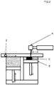
- a powder bed 1 is raised into the path of a spreading device 2 which spreads a thin layer of powder across a base-plate 3.
- the base-plate typically comprises a tool steel.
- Selected regions of the powder corresponding to a shape which it is intended to build are fused together (and also to the base-plate) by heat from laser 4.
- the base-plate 3 is gradually lowered with respect to the laser during the process enabling layer upon layer of powder to be applied and sintered by the laser. This layering process can create one or more components simultaneously.
- the component is optionally blasted with a blast media (for example, beads) to create a compressed layer at the external surface.
- a blast media for example, beads
- This compressed layer imposes a compressive force on underlying material resisting the propagation of cracks in the main body of the component.
- Benefits of an impacting process such as peening or grit blasting can be outweighed by the impacting medium creating dimensional variations and surface deformities which, in the case of gas turbine engine components, can impair performance of the end product. Consequently, a component must be designed such that these dimensional variations and surface deformities can be removed in a subtractive manufacturing process to provide a finished component to the desired geometry.
- the component and baseplate may then be subjected to a Hot Isostatic Pressing (HIP) step.
- HIP Hot Isostatic Pressing
- the HIP process substantially eliminates micro-cracks in the material structure, so improving the properties of the component material. This is a particularly important step for high-temperature nickel alloys (often used in the manufacture of gas turbine engine components), which when produced by DLD alone are very susceptible to cracking due to high micro-porosity and residual stresses in the component.
- the HIP step compresses the component whilst heating it.
- any structural elements and the base-plate are removed using a subtractive manufacturing process and finally, the remaining component may be subjected to a finishing operation.
- Subtracting manufacturing processes involve operations which remove material. Material removal is typically performed in two stages; in a first stage, roughing cuts are used to remove large amounts of material quickly to produce a shape close to the desired form, but leaving some material on the piece for a subsequent finishing operation.
- finishing cuts are used to complete the part and achieve the final dimension, tolerances, and surface finish of the component.
- finishing operations are carried out at lower feeds and depths, for example feeds of 0.0125-0.04 mm/rev and depths of 0.75-2.0 mm.
- Cutting speeds used for finishing operations are in general higher than those used in roughing cuts.
- a method for the manufacture of a component having a defined geometry and dimensions comprising, in sequence;
- the defined geometry and dimensions may include a tolerance range within which the product of step c) is included.
- the finishing operation of step b) desirably does not include an impacting process which roughens or textures a surface of the net shape of the component.
- the finishing operation may be a subtractive operation; that is it involves removal of a small amount of material at the surface of the net-shape component.
- the finishing operation does not involve additive manufacturing.
- the propagation of macro-cracks can be significantly reduced, thus the separate operations of surface compression (for example by peening or blasting) prior to heating, and roughing and finishing after a heating operation, can be replaced by a single operation performed prior to a heat treatment which may be a final heat treatment.
- the performance of such operations prior to a heat treatment is contrary to convention.
- Heat treatments are known to be a cause of distortion in non-uniform three dimensional shapes. Conventionally, such distortions are remedied by subsequent machining or bending processes.
- finishing operations include (without limitation); low stress grinding processes including electrochemical grinding and abrasive flow machining; polishing processes whether mechanical, chemical or chemical-mechanical; buffing, burnishing, soda blasting, brushing and linishing.
- low stress grinding processes including electrochemical grinding and abrasive flow machining; polishing processes whether mechanical, chemical or chemical-mechanical; buffing, burnishing, soda blasting, brushing and linishing.
- Other alternatives include conventional machining processes such as milling and turning where the process parameters such as feeds, depths and cutting speeds are carefully controlled as discussed above.
- the net shape comprises interim shape elements, the interim shape elements differing with respect to the defined component geometry such that during the heating step, the interim shape elements adjust to form the defined component geometry.
- the ALM step may further provide sacrificial support elements. Some or all of the sacrificial support elements may be removed in an interim step preceding the surface finishing operation. Alternatively, the sacrificial support elements may be removed after the heating step.
- the reduction or avoidance of operations performed on a component after heat treatment further decreases the likelihood of new stress concentrations being created in the finished product.
- the heat treatment step may involve HIP.
- the heat treatment step may involve annealing, normalising or tempering.
- Components made in accordance with the method of the invention may be incorporated into a gas turbine engine.
- a gas turbine engine is generally indicated at 10, having a principal and rotational axis 11.
- the engine 10 comprises, in axial flow series, an air intake 12, a propulsive fan 13, an intermediate pressure compressor 14, a high-pressure compressor 15, combustion equipment 16, a high-pressure turbine 17, and intermediate pressure turbine 18, a low-pressure turbine 19 and an exhaust nozzle 20.
- a nacelle 21 generally surrounds the engine 10 and defines both the intake 12 and the exhaust nozzle 20.
- the gas turbine engine 10 works in the conventional manner so that air entering the intake 12 is accelerated by the fan 13 to produce two air flows: a first air flow into the intermediate pressure compressor 14 and a second air flow which passes through a bypass duct 22 to provide propulsive thrust.
- the intermediate pressure compressor 14 compresses the air flow directed into it before delivering that air to the high pressure compressor 15 where further compression takes place.
- the compressed air exhausted from the high-pressure compressor 15 is directed into the combustion equipment 16 where it is mixed with fuel and the mixture combusted.
- the resultant hot combustion products then expand through, and thereby drive the high, intermediate and low-pressure turbines 17, 18, 19 before being exhausted through the nozzle 20 to provide additional propulsive thrust.
- the high 17, intermediate 18 and low 19 pressure turbines drive respectively the high pressure compressor 15, intermediate pressure compressor 14 and fan 13, each by suitable interconnecting shaft.
- gas turbine engines to which the present disclosure may be applied may have alternative configurations.
- such engines may have an alternative number of interconnecting shafts (e.g. two) and/or an alternative number of compressors and/or turbines.
- the engine may comprise a gearbox provided in the drive train from a turbine to a compressor and/or fan.
- components of the gas turbine engine could be manufactured by the method of the invention.
- components in the turbine sections 17, 18 and 19, or the combustor 16 may be manufactured in accordance with the invention.
- the method is well suited to the manufacture of components with non-linear geometries.
- Figure 2 has been discussed above.
- Figure 3 presents a flow chart of steps taken in sequence when performing a method in accordance with one embodiment of the invention.
Landscapes
- Chemical & Material Sciences (AREA)
- Engineering & Computer Science (AREA)
- Manufacturing & Machinery (AREA)
- Materials Engineering (AREA)
- Physics & Mathematics (AREA)
- Mechanical Engineering (AREA)
- Optics & Photonics (AREA)
- Ceramic Engineering (AREA)
- Chemical Kinetics & Catalysis (AREA)
- General Chemical & Material Sciences (AREA)
- Thermal Sciences (AREA)
- Inorganic Chemistry (AREA)
- Structural Engineering (AREA)
- Organic Chemistry (AREA)
- Powder Metallurgy (AREA)
Abstract
a) using an additive layer manufacturing process, building a three-dimensional net shape of the component;
b) applying a subtractive surface finishing operation to the product of step a);
c) applying a heat treatment to the product of step b) whereby to provide a component to the defined geometry and dimensions.
Description
- The present disclosure concerns the manufacture of an engineering component, for example a component of a gas turbine engine. More particularly, a method of manufacture involving an additive layer manufacturing (ALM) step and a heating step is described.
- Additive layer manufacturing (ALM) techniques are known for use in defining complex geometries to high tolerances and can be used as an alternative to casting. In these methods a component is built up layer by layer onto a base plate until the 3D component is defined. In some ALM methods, layers are created by selective treatment of layers within a mass of particulate material, the treatment causing cohesion of selected regions of particulates into a solid mass. For example, the particulate is a ferrous or non-ferrous alloy powder and the treatment involves local heating using a laser or electron beam. Specific examples of such ALM methods include (without limitation); laser sintering, laser melting, direct laser deposition (DLD) and electron beam melting (EBM).
- When the component is a high performance engineering component, for example, a component of a gas turbine engine, further treatment steps are often necessary to address porosity and/or weaknesses in the component surface which might result in failure of the component under high pressure, high stress and/or high temperature conditions. Processes are often impacting and may include blasting or peening the surface. Hot Isostatic Pressing (HIP) is one commonly used process which may be used optionally in addition to a blasting or peening step. Such a heat treatment is conventionally applied subsequent to any impacting method.
- A prior art method is now described with reference to the accompanying
Figure 2 . In the described method, a component is manufactured from a high-temperature alloy by a Powder Bed Direct Laser Deposition (PB DLD) or Direct Metal Laser Sintering (DMLS) additive manufacturing process. A powder bed 1 is raised into the path of a spreadingdevice 2 which spreads a thin layer of powder across a base-plate 3. The base-plate typically comprises a tool steel. - Selected regions of the powder corresponding to a shape which it is intended to build are fused together (and also to the base-plate) by heat from
laser 4. The base-plate 3 is gradually lowered with respect to the laser during the process enabling layer upon layer of powder to be applied and sintered by the laser. This layering process can create one or more components simultaneously. - Subsequent processing steps are performed on the component. Firstly, the component is optionally blasted with a blast media (for example, beads) to create a compressed layer at the external surface. This compressed layer imposes a compressive force on underlying material resisting the propagation of cracks in the main body of the component. Benefits of an impacting process such as peening or grit blasting can be outweighed by the impacting medium creating dimensional variations and surface deformities which, in the case of gas turbine engine components, can impair performance of the end product. Consequently, a component must be designed such that these dimensional variations and surface deformities can be removed in a subtractive manufacturing process to provide a finished component to the desired geometry.
- After the impacting process the component and baseplate may then be subjected to a Hot Isostatic Pressing (HIP) step. The HIP process substantially eliminates micro-cracks in the material structure, so improving the properties of the component material. This is a particularly important step for high-temperature nickel alloys (often used in the manufacture of gas turbine engine components), which when produced by DLD alone are very susceptible to cracking due to high micro-porosity and residual stresses in the component. The HIP step compresses the component whilst heating it.
- After the HIP process has been completed, any structural elements and the base-plate are removed using a subtractive manufacturing process and finally, the remaining component may be subjected to a finishing operation.
- Subtracting manufacturing processes involve operations which remove material. Material removal is typically performed in two stages; in a first stage, roughing cuts are used to remove large amounts of material quickly to produce a shape close to the desired form, but leaving some material on the piece for a subsequent finishing operation.
- In a finishing operation, finishing cuts are used to complete the part and achieve the final dimension, tolerances, and surface finish of the component.
- Typically, roughing operations are done at high feeds and depths, for example feeds of 0.4-1.25 mm/rev and depths of 2.5-20 mm. By contrast, finishing operations are carried out at lower feeds and depths, for example feeds of 0.0125-0.04 mm/rev and depths of 0.75-2.0 mm. Cutting speeds used for finishing operations are in general higher than those used in roughing cuts.
- According to a first aspect there is provided a method for the manufacture of a component having a defined geometry and dimensions comprising, in sequence;
- a) using an additive layer manufacturing process, building a three-dimensional net shape of the component;
- b) applying a finishing operation to the product of step a);
- c) applying a heat treatment to the product of step b) whereby to provide a component to the defined geometry and dimensions.
- The defined geometry and dimensions may include a tolerance range within which the product of step c) is included. The finishing operation of step b) desirably does not include an impacting process which roughens or textures a surface of the net shape of the component. The finishing operation may be a subtractive operation; that is it involves removal of a small amount of material at the surface of the net-shape component. The finishing operation does not involve additive manufacturing.
- By performing a surface finishing operation on the net shape prior to a subsequent heat treatment, the propagation of macro-cracks can be significantly reduced, thus the separate operations of surface compression (for example by peening or blasting) prior to heating, and roughing and finishing after a heating operation, can be replaced by a single operation performed prior to a heat treatment which may be a final heat treatment. The performance of such operations prior to a heat treatment is contrary to convention. Heat treatments are known to be a cause of distortion in non-uniform three dimensional shapes. Conventionally, such distortions are remedied by subsequent machining or bending processes.
- Examples of suitable finishing operations include (without limitation); low stress grinding processes including electrochemical grinding and abrasive flow machining; polishing processes whether mechanical, chemical or chemical-mechanical; buffing, burnishing, soda blasting, brushing and linishing. Other alternatives include conventional machining processes such as milling and turning where the process parameters such as feeds, depths and cutting speeds are carefully controlled as discussed above.
- Careful design of the component and any associated structural support can avoid problematic distortion during a subsequent heat treatment. For example, the Applicant's co-pending GB patent application no.
GB1514801.8 filed 20 August 2015 - a) defining a pre-component geometry comprising interim shape elements and additional, sacrificial elements for supporting interim shape elements;
- b) on a base plate, depositing multiple layers of a powder comprising a material from which the component is to be manufactured;
- c) sintering the powder to form the pre-component to the defined pre-component geometry;
- d) removing at least some of the sacrificial elements from the pre-component;
- e) subjecting the remaining pre-component from step d) to a HIP step; and,
- f) removing remaining sacrificial elements from the pre-component product of step e) to provide a component to the defined component geometry;
- However, if the sacrificial support elements are removed prior to the HIP step, for given HIP process parameters any deformation of shape elements during the HIP process is resultant from gravitational assistance and the orientation of the pre-component in the HIP furnace. The skilled person will appreciate that for a given defined shape and orientation and with a knowledge of the HIP processing parameters, the gravitational impact on the pre-component during the HIP step is predictable and can be determined.
GB1514801.8 filed 20 August 2015 - Thus, by anticipating and controlling net shape geometry through design of the net shape built during the ALM process, undesirable deformations in the defined geometry of the component during heat treatment can be avoided allowing a finishing process to be brought forward in the sequence of manufacturing steps. It will be understood that for some components, distortion during heat treatment might not present a problem. The method of the invention remains applicable to such components.
- Accordingly, in an option, the net shape comprises interim shape elements, the interim shape elements differing with respect to the defined component geometry such that during the heating step, the interim shape elements adjust to form the defined component geometry. Optionally the ALM step may further provide sacrificial support elements. Some or all of the sacrificial support elements may be removed in an interim step preceding the surface finishing operation. Alternatively, the sacrificial support elements may be removed after the heating step.
- The reduction or avoidance of operations performed on a component after heat treatment further decreases the likelihood of new stress concentrations being created in the finished product.
- The heat treatment step may involve HIP. Alternatively, the heat treatment step may involve annealing, normalising or tempering.
- Components made in accordance with the method of the invention may be incorporated into a gas turbine engine.
- The skilled person will appreciate that except where mutually exclusive, a feature described in relation to any one of the above aspects may be applied mutatis mutandis to any other aspect. Furthermore except where mutually exclusive any feature described herein may be applied to any aspect and/or combined with any other feature described herein.
- Embodiments will now be described by way of example only, with reference to the Figures, in which:
-
Figure 1 is a sectional side view of a gas turbine engine which may comprise components made in accordance with the method of the invention; -
Figure 2 shows schematically an additive layer manufacturing method known to be used in prior art manufacturing; -
Figure 3 shows an embodiment of a method in accordance with the invention. - With reference to
Figure 1 , a gas turbine engine is generally indicated at 10, having a principal androtational axis 11. Theengine 10 comprises, in axial flow series, anair intake 12, apropulsive fan 13, anintermediate pressure compressor 14, a high-pressure compressor 15,combustion equipment 16, a high-pressure turbine 17, andintermediate pressure turbine 18, a low-pressure turbine 19 and anexhaust nozzle 20. Anacelle 21 generally surrounds theengine 10 and defines both theintake 12 and theexhaust nozzle 20. - The
gas turbine engine 10 works in the conventional manner so that air entering theintake 12 is accelerated by thefan 13 to produce two air flows: a first air flow into theintermediate pressure compressor 14 and a second air flow which passes through abypass duct 22 to provide propulsive thrust. Theintermediate pressure compressor 14 compresses the air flow directed into it before delivering that air to thehigh pressure compressor 15 where further compression takes place. - The compressed air exhausted from the high-
pressure compressor 15 is directed into thecombustion equipment 16 where it is mixed with fuel and the mixture combusted. The resultant hot combustion products then expand through, and thereby drive the high, intermediate and low-pressure turbines nozzle 20 to provide additional propulsive thrust. The high 17, intermediate 18 and low 19 pressure turbines drive respectively thehigh pressure compressor 15,intermediate pressure compressor 14 andfan 13, each by suitable interconnecting shaft. - Other gas turbine engines to which the present disclosure may be applied may have alternative configurations. By way of example such engines may have an alternative number of interconnecting shafts (e.g. two) and/or an alternative number of compressors and/or turbines. Further the engine may comprise a gearbox provided in the drive train from a turbine to a compressor and/or fan.
- Many components of the gas turbine engine could be manufactured by the method of the invention. For example (but without limitation), components in the
turbine sections combustor 16 may be manufactured in accordance with the invention. The method is well suited to the manufacture of components with non-linear geometries. -
Figure 2 has been discussed above.Figure 3 presents a flow chart of steps taken in sequence when performing a method in accordance with one embodiment of the invention. - It will be understood that the invention is not limited to the embodiments above-described and various modifications and improvements can be made without departing from the concepts described herein. Except where mutually exclusive, any of the features may be employed separately or in combination with any other features and the disclosure extends to and includes all combinations and subcombinations of one or more features described herein.
Claims (12)
- A method for the manufacture of a component having a defined geometry and dimensions comprising, in sequence;a) using an additive layer manufacturing process, building a three-dimensional net shape of the component;b) applying a subtractive surface finishing operation to the product of step a);c) applying a heat treatment to the product of step b) whereby to provide a component to the defined geometry and dimensions.
- A method as claimed in claim 1 wherein the subtractive surface finishing operation removes not more than 2mm from the surface of the product of step a).
- A method as claimed in claim 1 or 2 wherein the net shape comprises interim shape elements and the interim shape elements differ with respect to the component defined geometry and/or dimensions such that during the heating step, the interim shape elements adjust to form the defined component defined geometry and dimensions.
- A method as claimed in claim 1, 2 or 3 wherein the component defined geometry and dimensions includes a tolerance range within which the product of step c) is included.
- A method as claimed in any preceding claim wherein the finishing operation of step b) is selected from; a low stress grinding process, electrochemical grinding, abrasive flow machining, mechanical polishing, chemical polishing, chemical-mechanical polishing, buffing, burnishing, soda blasting, brushing and linishing.
- A method as claimed in any of claims 1 to 4 wherein the finishing operation of step b) is a milling or turning operation wherein the feeds are maintained at or below 0.04 mm/rev and cuts are to a depth of 2 mm or less.
- A method as claimed in any preceding claim further including, in the additive layer manufacturing process step providing sacrificial support elements which are removed in an interim step preceding the surface finishing operation.
- A method as claimed in any preceding claim wherein the additive layer manufacturing process of step a) involves fusing of a powder which comprises a ferrous or non-ferrous alloy, or a ceramic.
- A method as claimed in claim 8 wherein fusing of the powder is achieved using a laser or an electron beam.
- A method as claimed in any preceding claim wherein the additive layer manufacturing process of step a) is a powder bed process.
- A method as claimed in any preceding claim wherein the heat treatment of step c) is hot isostatic pressing (HIP).
- A method as claimed in any of claims 1 to 10 wherein the heat treatment is selected from annealing, normalising or tempering.
Applications Claiming Priority (1)
| Application Number | Priority Date | Filing Date | Title |
|---|---|---|---|
| GB201605702 | 2016-04-04 |
Publications (1)
| Publication Number | Publication Date |
|---|---|
| EP3228406A1 true EP3228406A1 (en) | 2017-10-11 |
Family
ID=58265871
Family Applications (1)
| Application Number | Title | Priority Date | Filing Date |
|---|---|---|---|
| EP17160056.2A Withdrawn EP3228406A1 (en) | 2016-04-04 | 2017-03-09 | Method of manufacture of a component |
Country Status (2)
| Country | Link |
|---|---|
| US (1) | US20170282454A1 (en) |
| EP (1) | EP3228406A1 (en) |
Cited By (2)
| Publication number | Priority date | Publication date | Assignee | Title |
|---|---|---|---|---|
| CN108356526A (en) * | 2018-02-08 | 2018-08-03 | 上海理工大学 | A kind of process equipment that increase and decrease material is integrally manufactured |
| EP3357605A1 (en) * | 2017-02-06 | 2018-08-08 | Rolls-Royce plc | Manufacturing method and post-processing treatment |
Families Citing this family (2)
| Publication number | Priority date | Publication date | Assignee | Title |
|---|---|---|---|---|
| EP3663878A1 (en) * | 2018-12-04 | 2020-06-10 | Siemens Aktiengesellschaft | Method of designing an intermediate product, computer pro-gram product, method of additive manufacturing, method of manufacturing a component and a corresponding component |
| US12435932B2 (en) | 2022-10-21 | 2025-10-07 | General Electric Company | Heat exchanger assembly formed of a lattice structure with a plurality of shell structure unit cells |
Citations (7)
| Publication number | Priority date | Publication date | Assignee | Title |
|---|---|---|---|---|
| US8383985B2 (en) * | 2007-02-21 | 2013-02-26 | United Technologies Corporation | System and method for an integrated additive manufacturing cell for complex components |
| US20140034626A1 (en) * | 2012-08-06 | 2014-02-06 | Materials Solutions | Additive manufacturing |
| EP2777867A1 (en) * | 2013-03-12 | 2014-09-17 | Honeywell International Inc. | Methods for the repair of gas turbine engine components using additive manufacturing techniques |
| US9192999B2 (en) * | 2013-07-01 | 2015-11-24 | General Electric Company | Methods and systems for electrochemical machining of an additively manufactured component |
| EP3165305A1 (en) * | 2015-11-05 | 2017-05-10 | Honeywell International Inc. | Surface improvement of additively manufactured articles produced with aluminum alloys |
| WO2017087944A1 (en) * | 2015-11-20 | 2017-05-26 | Titan Spine, Llc | Processes for additively manufacturing orthopedic implants |
| WO2017124097A1 (en) * | 2016-01-14 | 2017-07-20 | Arccinic Inc. | Methods for producing additively manufactured products |
Family Cites Families (3)
| Publication number | Priority date | Publication date | Assignee | Title |
|---|---|---|---|---|
| EP2836168B1 (en) * | 2012-04-13 | 2016-09-28 | ConforMIS, Inc. | Methods for additive manufacturing of implant components |
| GB201317757D0 (en) * | 2013-10-08 | 2013-11-20 | Rolls Royce Plc | A method of manufacturing an article by hot pressing and ultrasonically inspecting the article |
| CN103567726B (en) * | 2013-11-18 | 2015-01-07 | 中国科学院近代物理研究所 | Manufacturing method of superconductor cavity |
-
2017
- 2017-03-09 EP EP17160056.2A patent/EP3228406A1/en not_active Withdrawn
- 2017-03-09 US US15/454,513 patent/US20170282454A1/en not_active Abandoned
Patent Citations (9)
| Publication number | Priority date | Publication date | Assignee | Title |
|---|---|---|---|---|
| US8383985B2 (en) * | 2007-02-21 | 2013-02-26 | United Technologies Corporation | System and method for an integrated additive manufacturing cell for complex components |
| US20140034626A1 (en) * | 2012-08-06 | 2014-02-06 | Materials Solutions | Additive manufacturing |
| EP2777867A1 (en) * | 2013-03-12 | 2014-09-17 | Honeywell International Inc. | Methods for the repair of gas turbine engine components using additive manufacturing techniques |
| US9192999B2 (en) * | 2013-07-01 | 2015-11-24 | General Electric Company | Methods and systems for electrochemical machining of an additively manufactured component |
| EP3165305A1 (en) * | 2015-11-05 | 2017-05-10 | Honeywell International Inc. | Surface improvement of additively manufactured articles produced with aluminum alloys |
| WO2017087944A1 (en) * | 2015-11-20 | 2017-05-26 | Titan Spine, Llc | Processes for additively manufacturing orthopedic implants |
| EP3377255A1 (en) * | 2015-11-20 | 2018-09-26 | Titan Spine, Inc. | Processes for additively manufacturing orthopedic implants |
| WO2017124097A1 (en) * | 2016-01-14 | 2017-07-20 | Arccinic Inc. | Methods for producing additively manufactured products |
| EP3402620A1 (en) * | 2016-01-14 | 2018-11-21 | Arconic Inc. | Methods for producing additively manufactured products |
Cited By (2)
| Publication number | Priority date | Publication date | Assignee | Title |
|---|---|---|---|---|
| EP3357605A1 (en) * | 2017-02-06 | 2018-08-08 | Rolls-Royce plc | Manufacturing method and post-processing treatment |
| CN108356526A (en) * | 2018-02-08 | 2018-08-03 | 上海理工大学 | A kind of process equipment that increase and decrease material is integrally manufactured |
Also Published As
| Publication number | Publication date |
|---|---|
| US20170282454A1 (en) | 2017-10-05 |
Similar Documents
| Publication | Publication Date | Title |
|---|---|---|
| US10472971B2 (en) | Method of manufacture of a turbine component | |
| US10710161B2 (en) | Turbine disk fabrication with in situ material property variation | |
| EP0968316B1 (en) | Method of treating metal components | |
| EP3702069B1 (en) | Titanium aluminide components from articles formed by consolidation processes | |
| US9039917B2 (en) | Methods for manufacturing components from articles formed by additive-manufacturing processes | |
| EP3696296B1 (en) | Structured material alloy component fabrication | |
| EP2620240B1 (en) | Hollow airfoil construction utilizing functionally graded materials | |
| EP3228406A1 (en) | Method of manufacture of a component | |
| US7043819B1 (en) | Methods for forming metal parts having superior surface characteristics | |
| US11458591B2 (en) | Surface modification using abrasive blasting | |
| WO2014116256A1 (en) | Solid state metal powder consolidation for structural components | |
| GB2541810A (en) | Additive manufacturing | |
| EP3357605A1 (en) | Manufacturing method and post-processing treatment | |
| JP2022185044A (en) | Method for manufacturing metal alloy parts having complex shapes | |
| US20100129255A1 (en) | Joining and a repair method | |
| Xue et al. | Laser consolidation: a novel additive manufacturing process for making net-shape functional metallic components for gas turbine applications | |
| WO2019186602A1 (en) | Turbine impeller and manufacturing method for the same | |
| EP3415253A1 (en) | Heat treatment after alm of gamma'-strengthened nickel based superalloy component | |
| CN116511486A (en) | A nickel-based superalloy powder and alloy laser selective melting forming method | |
| CN118166300A (en) | A TiAl alloy composite strengthening method | |
| Magerramova et al. | Peculiarities of additive technologies application in the production of gas turbine engine parts | |
| CN115740499B (en) | A method for 3D printing of nickel-based high-temperature alloy/copper alloy dissimilar metal components | |
| Sharma et al. | Post-processing of additive manufactured components through abrasive flow machining process | |
| US10351940B2 (en) | Method of manufacturing a component from a nickel-based superalloy | |
| Huang | Near-Net-Shape Hot Isostatic Press Manufacturing Modality for sCO2 CSP Capital Cost Reduction |
Legal Events
| Date | Code | Title | Description |
|---|---|---|---|
| PUAI | Public reference made under article 153(3) epc to a published international application that has entered the european phase |
Free format text: ORIGINAL CODE: 0009012 |
|
| STAA | Information on the status of an ep patent application or granted ep patent |
Free format text: STATUS: THE APPLICATION HAS BEEN PUBLISHED |
|
| AK | Designated contracting states |
Kind code of ref document: A1 Designated state(s): AL AT BE BG CH CY CZ DE DK EE ES FI FR GB GR HR HU IE IS IT LI LT LU LV MC MK MT NL NO PL PT RO RS SE SI SK SM TR |
|
| AX | Request for extension of the european patent |
Extension state: BA ME |
|
| STAA | Information on the status of an ep patent application or granted ep patent |
Free format text: STATUS: REQUEST FOR EXAMINATION WAS MADE |
|
| 17P | Request for examination filed |
Effective date: 20180410 |
|
| RBV | Designated contracting states (corrected) |
Designated state(s): AL AT BE BG CH CY CZ DE DK EE ES FI FR GB GR HR HU IE IS IT LI LT LU LV MC MK MT NL NO PL PT RO RS SE SI SK SM TR |
|
| RAP1 | Party data changed (applicant data changed or rights of an application transferred) |
Owner name: ROLLS-ROYCE PLC |
|
| STAA | Information on the status of an ep patent application or granted ep patent |
Free format text: STATUS: EXAMINATION IS IN PROGRESS |
|
| 17Q | First examination report despatched |
Effective date: 20200904 |
|
| STAA | Information on the status of an ep patent application or granted ep patent |
Free format text: STATUS: THE APPLICATION IS DEEMED TO BE WITHDRAWN |
|
| 18D | Application deemed to be withdrawn |
Effective date: 20210115 |