EP3228351A1 - Transvascular nerve stimulation apparatus - Google Patents
Transvascular nerve stimulation apparatus Download PDFInfo
- Publication number
- EP3228351A1 EP3228351A1 EP17169051.4A EP17169051A EP3228351A1 EP 3228351 A1 EP3228351 A1 EP 3228351A1 EP 17169051 A EP17169051 A EP 17169051A EP 3228351 A1 EP3228351 A1 EP 3228351A1
- Authority
- EP
- European Patent Office
- Prior art keywords
- electrodes
- nerve stimulation
- tubular member
- catheter
- electrode structure
- Prior art date
- Legal status (The legal status is an assumption and is not a legal conclusion. Google has not performed a legal analysis and makes no representation as to the accuracy of the status listed.)
- Granted
Links
Images


Classifications
-
- A—HUMAN NECESSITIES
- A61—MEDICAL OR VETERINARY SCIENCE; HYGIENE
- A61N—ELECTROTHERAPY; MAGNETOTHERAPY; RADIATION THERAPY; ULTRASOUND THERAPY
- A61N1/00—Electrotherapy; Circuits therefor
- A61N1/02—Details
- A61N1/04—Electrodes
- A61N1/05—Electrodes for implantation or insertion into the body, e.g. heart electrode
- A61N1/0551—Spinal or peripheral nerve electrodes
-
- A—HUMAN NECESSITIES
- A61—MEDICAL OR VETERINARY SCIENCE; HYGIENE
- A61N—ELECTROTHERAPY; MAGNETOTHERAPY; RADIATION THERAPY; ULTRASOUND THERAPY
- A61N1/00—Electrotherapy; Circuits therefor
- A61N1/18—Applying electric currents by contact electrodes
- A61N1/32—Applying electric currents by contact electrodes alternating or intermittent currents
- A61N1/36—Applying electric currents by contact electrodes alternating or intermittent currents for stimulation
- A61N1/3601—Applying electric currents by contact electrodes alternating or intermittent currents for stimulation of respiratory organs
-
- A—HUMAN NECESSITIES
- A61—MEDICAL OR VETERINARY SCIENCE; HYGIENE
- A61N—ELECTROTHERAPY; MAGNETOTHERAPY; RADIATION THERAPY; ULTRASOUND THERAPY
- A61N1/00—Electrotherapy; Circuits therefor
- A61N1/18—Applying electric currents by contact electrodes
- A61N1/32—Applying electric currents by contact electrodes alternating or intermittent currents
- A61N1/36—Applying electric currents by contact electrodes alternating or intermittent currents for stimulation
- A61N1/3605—Implantable neurostimulators for stimulating central or peripheral nerve system
Definitions
- the invention relates to neurophysiology and in particular to apparatus and methods for stimulating nerves through the walls of blood vessels.
- Non-limiting embodiments include nerve stimulation apparatus, electrode structures, electrodes and related methods.
- Nerve stimulation can be applied in the treatment of a range of conditions. Nerve stimulation may be applied to control muscle activity or to generate sensory signals. Nerves may be stimulated by surgically implanting electrodes in or near the nerves and driving the electrodes from an implanted or external source of electricity.
- the phrenic nerves nominally carry signals that cause the contractions of the diaphragm that arc necessary for breathing. Various conditions can prevent appropriate signals from being delivered to the phrenic nerves. These include:
- Mechanical ventilation may be used to help patients breathe. Some patients require chronic mechanical ventilation and many more patients require temporary mechanical ventilation. Mechanical ventilation can be lifesaving but has a range of significant problems and/or side effects. Mechanical ventilation:
- a patient on mechanical ventilation is tied to a ventilator, and does not breathe independently. This can lead to atrophy of the diaphragm muscle (ventilator induced diaphragmatic dysfunction; VIDD) and an overall decline in well being. Muscle atrophy can occur surprisingly rapidly and can be a serious problem.
- VIDD ventilation induced diaphragmatic dysfunction
- the central respiratory drive of the diaphragm is suppressed.
- the inactivity of the diaphragm muscle causes rapid disuse atrophy.
- the diaphragm muscle could shrink by 52-57% after just 18-69 hours of mechanical ventilation and sedation.
- Ventilator-induced diaphragm atrophy could cause a patient to become ventilator-dependent.
- Patients in intensive care units (ICU) who become dependent on mechanical ventilation (MV) are at high risk of complications such as ventilator-acquired pneumonia (VAP) and nosocomial infections and are seven times more likely to die in the ICU.
- VAP ventilator-acquired pneumonia
- Phrenic nerve pacing uses electrodes implanted in the chest to directly stimulate the phrenic nerves.
- the Mark IV Breathing Pacemaker System available from Avery Biomedical Devices, Inc. of Commack, New York, USA, is a diaphragmatic or phrenic nerve stimulator that has surgically implanted receivers and electrodes mated to an external transmitter by antennas worn over the implanted receivers.
- Implanting electrodes and other implantable components for phrenic nerve pacing requires significant surgery. The surgery is risky and complicated by the fact that phrenic nerves are thin (approximately 2 mm in diameter) and delicate. The surgery involves significant cost.
- Laproscopic diaphragm pacing developed by biomedical engineers and physician researchers at Case Western Reserve University is another technique for controlling breathing.
- Laproscopic diaphragm pacing involves placing electrodes at motor points of the diaphragm.
- Method 3 has advantages over Methods 1 and 2, because it does not require invasive surgery that would typically be performed under full anaesthesia. Furthermore, ICU patients are not typically eligible for Methods 1 and 2.
- This invention has a number of aspects. Aspects of the invention include: designs for intravascular electrodes; electrode structures; nerve stimulation apparatus; intravascular apparatus including electrodes and structures for introducing and supporting the electrodes; catheters equipped with electrodes; methods for nerve stimulation; and methods for measuring the location of an electrode structure within a blood vessel relative to a target nerve. While these and other aspects may be applied together, individual aspects may be applied separately as well as in other combinations and contexts. For example, electrode structures as described herein may be applied in combination with various deployment systems known in the art for various diagnostic and/or therapeutic applications.
- aspects of the invention may be applied for restoring breathing, treating conditions such as muscle atrophy, chronic pain, and other uses involving nerve stimulation. Aspects of the invention may be applied in the treatment of acute or chronic conditions. Aspects of the invention may be applied to conveniently deploy and remove electrode structures in a patient.
- One aspect of the invention relates to transvascular stimulation of nerves.
- transvascular stimulation suitable arrangements of one or more electrodes are positioned in a blood vessel that passes close to a nerve to be stimulated. Electrical currents pass from the electrodes through a wall of the blood vessel to stimulate the target nerve.
- FIG. 1A illustrates the anatomy of selected nerves and blood vessels in the neck and chest of a human and, in particular, the relative locations of the left and right phrenic nerves (PhN), vagus nerves (VN), internal jugular veins (IJV), brachiocephalic veins (BCV), superior vena cava (SVC) and left subclavian vein (LSV).
- PhN left and right phrenic nerves
- VN vagus nerves
- IJV internal jugular veins
- BCV brachiocephalic veins
- SVC superior vena cava
- LSV left subclavian vein
- Apparatus provides intravascular electrode systems which include one or more electrodes supported on an elongated resiliently flexible support member.
- the support member may be used to introduce the electrodes into a blood vessel. As the support member is introduced into the blood vessel the support member bends to follow the path of the blood vessel. Restoring forces resulting from the resilience of the support member hold the one or more electrodes in place against the wall of the blood vessel.
- the electrode structure may comprise flexible electrically insulating pads that insulate electrodes from being in direct contact with blood in the main passage of the blood vessel.
- the apparatus includes two or more electrodes at spaced-apart locations along the support member. Spacing between the electrodes may be selected to allow the electrodes to be located proximate to anatomical structures, for example nerves passing nearby the blood vessel.
- electrodes are spaced apart on a support structure and oriented so that an intravascular electrode system may be placed with electrodes located to stimulate a patient's left and right phrenic nerves.
- the electrodes may optionally have different circumferential orientations with respect to a longitudinal centerline of the support structure.
- the support member is more flexible in one direction than in another. This can help to preserve a desired orientation of electrodes while the electrode system is being introduced into a blood vessel.
- the electrode system comprises a catheter having one or more lumens.
- the catheter may provide the functionality of a central catheter of the type commonly used in intensive care units, for example.
- Such embodiments provide the advantage of electrodes that may be applied, for example, for stimulating nerves (e.g. for diaphragm pacing) and/or for monitoring electrical activity in the body of a patient in the same package as a central catheter that may be required in any event.
- the catheter also serves as a support structure as described above.
- Some embodiments comprise electrode structures comprising electrodes and asymmetrical electrically-insulating backing sheets.
- the backing sheets can electrically isolate the electrodes from blood in the lumen of a blood vessel, thereby allowing more efficient stimulation of extravascular structures such as nearby nerves.
- the asymmetrical arrangement of the backing sheet allows the backing sheet to be rolled into a compact configuration for insertion of the electrode structure into a blood vessel while providing a backing sheet that can provide electrical insulation for two or more electrodes.
- the backing sheet has a generally trapezoidal configuration.
- the backing sheet may be formed so that it tends to unroll from the rolled configuration.
- the backing sheet may be formed with a natural curvature similar to that of a wall of a blood vessel against which the backing sheet will be deployed.
- the backing sheet may be but need not be completely electrically insulating. Such a backing sheet can be advantageous as long as it provides a resistance to the flow of electricity substantially greater than the resistance that would be provided by blood in the blood vessel in the absence of the backing sheet.
- Such electrode structures may be applied in a wide range of intravascular applications.
- Electrodes structures that include a retainer that holds a backing sheet in place.
- the retainer may comprise, for example, a formed piece of wire that extends through apertures in the backing sheet.
- the retainer comprises a pair of wire sections, which may be generally parallel, that are each woven through apertures in the backing sheet. Distal ends of the wire sections may be joined. The wire sections may be parts of a continuous wire. Distal ends of the wire sections may be bent back over the backing sheet.
- the retainer is electrically conductive and may be applied as one electrode, for example a reference electrode for electrical measurements and/or one of two or more electrodes for delivery of stimulation.
- the backing sheet may be rolled around the retainer for introduction into a blood vessel. Such electrode structures may be applied in a wide range of applications.
- Some embodiments provide electrode structures in which a backing sheet for one or more electrodes is provided by a wall of an inflatable structure.
- the structure may be inflated to hold the electrodes against a wall of a blood vessel.
- the structure may, for example, be located on a side of a catheter or other support member.
- inflation of the inflatable structure actuates a backing member carrying one or more electrodes to move toward engagement with a wall of a blood vessel.
- Some embodiments provide intravascular electrode structures on which one or more electrodes is supported on a support member which include integrated position-measurement transducers for measuring a displacement of an electrode along a blood vessel into which the electrode is being inserted.
- the apparatus including the position-measurement transducers may be intended to be disposable after a single use.
- Various embodiments of example position measurement transducers that can provide accurate position measurement in a suitable form factor and/or may be fabricated inexpensively are described below.
- the following description describes examples of nerve stimulation apparatus and components suitable for application in nerve stimulation.
- the examples given are adapted for stimulation of phrenic nerves in a human or other mammals.
- the nerve stimulation apparatus described herein has a number of features which are particularly advantageous in combination with one another but can also be used individually, in other combinations, or in combination with the features described in US2010/00336451 .
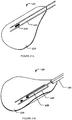
- Figs. 2A-2C are schematics of a nerve stimulation apparatus 10 according to an example embodiment of the invention.
- Nerve stimulation apparatus 10 comprises electrode structures 12A, 12B (collectively 12).
- Nerve stimulation apparatus 10 also comprises a tubular member 24.
- Tubular member 24 may be a catheter or cannula-type tubular member.
- tubular member 24 may be a central venous catheter.
- Tubular member 24 is capable of being inserted into a lumen of a blood vessel.
- Tubular member 24 has a distal end 26, a proximal end 28, an outer wall or sheath 30 that extends from distal end 26 to proximal end 28.
- Tubular member 24 may comprise one or more internal lumens (not specifically indicated in Figs. 2A-2C - examples of such lumens are shown in other Figs.)
- tubular member 24 may be a multi-lumen catheter.
- At least one lumen extends longitudinally from proximal end 28 to distal end 26.
- the lumens may have exit openings on wall 30 of tubular member 24. These openings may be spaced apart along the length of tubular member 24.
- the lumens may be used for removing blood samples, inserting medication, delivering fluids or nutrients, measuring chemical or physical parameters in blood, such as pH or temperature, and the like.
- agents may be applied through one or more of the openings to prevent clot formation on electrode structures 12.
- Fig. 2A an example opening 34 is shown, which provides an exit port for electrode structure 12B. Opening 34 may be upstream from electrode structure 12B relative to a direction of blood flow in a blood vessel in which nerve stimulation apparatus 10 is deployed.
- Tubular member 24 may be flexible. A range of materials may be used for construction of tubular member 24, including silicone, polyurethane, or other suitable polymers, stainless steel, and the like. Tubular member 24 may have markings for length determination. In some embodiments, tubular member 24 is more flexible in one bending direction than in another bending direction. In some embodiments, different sections of tubular member 24 have different levels of flexibility. For example, the distal part of tubular member 24 may be more flexible than the proximal part of tubular member 24.
- Electrode structure 12A is positioned at or near distal end 26 of tubular member 24. Electrode structure 12B is positioned at a mid-portion of tubular member 24. Electrode structures 12A, 12B are movable between a retracted position (i.e., received in tubular member 24) and a deployed position (i.e., extending out of tubular member 24). When electrode structures 12A, 12B are in a retracted position, electrode structures 12A, 12B are located inside or mostly inside tubular member 24 ( Fig. 2A ).
- electrode structure 12A, 12B When electrode structure 12A, 12B are in a deployed position, electrode structure 12A extends out of a distal opening of tubular member 24, and electrode structure 12B extends out of tubular member 24 from an opening 34 on wall 30 ( Figs. 2B and 2C ).
- electrode structure 12 is dimensioned so that, when in a deployed position inside a blood vessel, it will extend approximately 45° to 60° of the way around a wall of the blood vessel, although this is not mandatory.
- each electrode structure 12 may comprise a plurality of electrodes.
- one or more electrodes may be used for stimulating a target nerve; and one or more additional electrodes may be used for ECG monitoring.
- one electrode may function as a cathode and another electrode may function as an anode.
- Electrode structure 20 also comprises an insulating pad 42.
- Each electrode structure 12 may be coupled to an elongated flexible shaft portion 14 which extends inside tubular member 24.
- Shaft portion 14 is not directly visible in Figs. 2A-2C , but Fig. 2D schematically shows a shaft portion 14 coupled to electrode 12A, without tubular member 24.
- elongated flexible shaft portion 14 has a distal end 16 and a proximal end 18.
- Electrode structure 12A is coupled to distal end 16 of shaft portion 14.
- Shaft portion 14 may comprise, for example, a single wire or tube or a plurality of wires or tubes.
- Shaft portion 14 may comprise one or more suitable leads (not specifically indicated in Fig.
- leads may be hidden inside shaft portion 14) which may electrically couple one or more electrodes 20 to an apparatus for monitoring electrical activity and/or delivering electrical stimulation by way of electrodes 20.
- the leads and the electrodes 20 may be electrically coupled in a one-to-one relationship such that each electrode 20 is individually addressable. In some embodiments, some groups of two or more electrodes 20 are connected to a common lead.
- the leads may be carried in or along shaft portion 14.
- shaft portion 14 may have a configuration that is straight or curved.
- Shaft portion 14 may have an initial radius of curvature greater than a radius of curvature of the left brachiocephalic vein (BCV) and superior vena cava (SVC) into which nerve stimulation apparatus 10 may be introduced.
- Shaft portion 14 may be resilient and tending to return to its original configuration; thus, distal end 16 of shaft portion 14 tends to spring toward the far wall of the superior vena cava (SVC) when nerve stimulation apparatus 10 is inserted in a patient from the left side of the body (e.g., from LSV into BCV and SVC). This is convenient because the right phrenic nerve typically runs alongside the far wall of the superior vena cava (SVC) at this point.
- SVC superior vena cava
- shaft portion 14 is more flexible in one direction than in another direction.
- shaft portion 14 may be oriented such that it is easier to bend downwardly than sideways. This facilitates insertion and positioning of shaft portion 14 in SVC which extends downwardly from the BCV.
- shaft portion 14 has different levels of flexibility.
- the distal part of shaft portion 14 may be more flexible than the proximal part of shaft portion 14.
- flexibility of the shaft portion may vary along the length of the shaft portion.
- Shaft portion 14 may be made of stainless steel or other suitable material (e.g., Nitinol, high-density plastics, elastomers etc.).
- shaft portion 14 comprises a pair of flexible stainless steel tubes that are attached together by, for example, welding.
- Nerve stimulation apparatus 10 may be inserted into a person's subclavian vein and SVC as follows.
- the electrode structures 12A, 12B are initially located within tubular member 24.
- a percutaneous puncture is made into the patient's LSV.
- Tubular member 24 is then inserted through the puncture into the LSV. Such insertion could be done under local anaesthesia. General anaesthesia is typically not required.
- Tubular member 24 of nerve stimulation apparatus 10 is then advanced into the patient's left BCV and eventually into SVC. Care should be taken not to advance tubular member 24 into the right atrium of the heart.
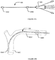
- Electrode structures 12A, 12B are moved from a retracted position ( Fig. 3B ) to a deployed position ( Fig. 3C ). Electrode structures 12A, 12B are positioned adjacent the left and right phrenic nerves. As described below, monitoring may be performed during insertion to locate the electrode positions which allow for most effective stimulation of the phrenic nerve.
- electrode structures 12A, 12B extend out of tubular member 24. Electrodes 20 are pressed against a wall of the blood vessel, whereas the insulating pads 42 of the electrode structures 12A, 12B prevent the electrodes 20 from being in close electrical contact with the bulk of the blood flowing through the blood vessel.
- the curvature of nerve stimulation apparatus 10 may conform to the curvature of the patient's left BCV and SVC.
- the two electrode structures 12A, 12B may be arranged roughly at 90" to one another about the longitudinal axis of nerve stimulation apparatus 10, with electrode structure 12A oriented toward the right phrenic nerve and electrode structure 12B oriented toward the left phrenic nerve.
- Electrodes 12A, 12B may be located at desired positions relative to the left and right phrenic nerve. Methods for locating an electrode structure relative to a target nerve are described below herein (see Figs. 28A, 28B ). Measurements can also be made to determine which electrode or electrodes of an electrode structure comprising multiple electrodes most effectively stimulate the target nerve.
- Electrodes 20 are electrically coupled to a stimulation device (e.g., a pulse generator which may be optionally located outside the body) to apply electric current to the phrenic nerves, causing the diaphragm muscle to contract.
- a stimulation device e.g., a pulse generator which may be optionally located outside the body
- the contraction of the diaphragm muscle causes inhalation of air into the lungs.
- the electric stimulation of the phrenic nerves is stopped, the diaphragm muscle relaxes and exhalation occurs. This allows the patient to breathe more naturally.
- Nerve stimulation apparatus 10 may be used in combination with a control unit (e.g., a bedside control unit).
- Nerve stimulation apparatus 10 may be removed from the patient's body. During removal, electrode structures 12A, 12B may be first moved from a deployed configuration ( Fig. 3C ) to a retracted configuration ( Fig. 3B ). Once the electrode structures 12A, 12B are retrieved into tubular member 24, the entire nerve stimulation apparatus 10 may be withdrawn from the patient's body. Alternatively, removing may not require retraction of electrode structure into the tubular member.
- Preferred methods for retrieving nerve stimulation apparatus 10 from the patient's body have a number of advantages which include one or more of: (1) nerve stimulation apparatus 10 can be repositioned easily for replacement or if the electrode moves with respect to target nerves, for example while the patient is being moved or transferred; (2) periodic removal of nerve stimulation apparatus prevents the build-up of plaques, or inflammation, or other undesirable physiological or pathological consequences as a result of implanting nerve stimulation apparatus in a blood vessel; (3) nerve stimulation apparatus 10 can be conveniently removed from the patient when nerve stimulation treatment is no longer needed.
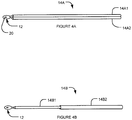
- Shaft portion 14 may take a number of different configurations.
- a shaft portion 14A comprises a pair of tubes 14A1, 14A2 that are joined together in parallel.
- Tubes 14A1, 14A2 may be welded or affixed in another suitable manner together at certain spaced apart points or continuously along their length.
- Tubes 14A1, 14A2 may be made of stainless steel or other suitable material.
- the two-tube configuration in Fig. 4A allows shaft portion 14A to bend more easily in a plane extending between the two tubes than in a plane of the two tubes.
- a shaft portion 14B comprises a pair of tubes 14B1, 14B2 that are coupled together in a concentric fashion.
- Tube 14B1 has a smaller diameter than tube 14B2 and is insertable and movable in tube 14B2.
- Tube 14B1 is distal to tube 14B2.
- Tube 14B1 may be more flexible than tube 14B2.
- Figs. 5A and 5B are schematic views of a nerve stimulation apparatus 10C according to an example embodiment of the invention (in a deployed configuration and a retracted configuration respectively).
- electrode structure 12AC is coupled to a distal end of shaft portion 14C
- electrode structure 12BC is coupled to a mid-portion of shaft portion 14C.
- the coupling between electrode structure 12B and shaft portion 14C may comprise a spring mechanism 35C.
- Electrode structure 12AC is retractable and extendable through a distal opening of tubular member 24C.
- Electrode structure 12BC is retractable and extendable through a side opening 34C of tubular member 24C.
- Figs. 6A and 6B are schematic views of a nerve stimulation apparatus 10D according to another example embodiment of the invention.
- nerve stimulation apparatus 10D comprises a first tubular member 24D and a second tubular member 36D.
- Electrode structure 12AD is coupled to a distal end of shaft portion 14D.
- electrode structure 12BD is disposed on first tubular member 24D.
- first tubular member 24D passes through second tubular member 36D and electrode structure 12BD is retractable into second tubular member 36D.
- First and second tubular members 24D, 36D may be assembled in a telescoping fashion.
- Second tubular member 36D has a diameter greater than the diameter of first tubular member 24D.
- Second tubular member 36D is typically shorter than first tubular member 24D.
- the position of electrode structures 12AD, 12BD may be controlled independently from one another via shaft portion 14D and tubular member 24D respectively.
- Figs. 7A and 7B are schematic views of a nerve stimulation apparatus 10E according to another example embodiment of the invention.
- electrode structure 12AE is coupled to a shaft portion 14E1
- electrode structure 12BE is disposed on a shaft portion 14E2 which is separate from shaft portion 14E1.
- Shaft portion 14E2 may be structurally different from shaft portion 14E1.
- Shaft portions 14E1, 14E2 may be independently controlled to deploy or retract electrode structures 12AE, 12BE, respectively.
- first tubular member 24E passes through a second tubular member 36E.
- Electrode structure 12AE is retractable into first tubular member 24E.
- Electrode structure 12BE is retractable into second tubular member 36E.
- Second tubular member 36E has a diameter greater than the diameter of first tubular member 24E.
- Second tubular member 36E is typically shorter than first tubular member 24E.
- Fig. 8 schematically shows a nerve stimulation apparatus 10F according to another example embodiment of the invention.
- electrode structure 12AF is coupled to a shaft portion 14F1
- electrode structure 12BF is disposed on a shaft portion 14F2 which is separate from shaft portion 14F1.
- Shaft portion 14F2 may be structurally different from shaft portion 14F1.
- Shaft portions 14F1, 14F2 may be independently controlled to deploy or retract electrode structures 12AF, 12BF, respectively.
- Tubular member 24F comprises a single lumen 32F. Both shaft portions 14F1 and 14F2 extend inside lumen 32F.
- Electrode structure 12AF may extend out of a distal opening of lumen 32F.
- Electrode structure 12BF may extend out of a side opening 34F of tubular member 24F.
- FIG. 9 schematically shows a nerve stimulation apparatus 10G according to another example embodiment of the invention.
- Apparatus 10G is similar to apparatus 10F except that tubular member 24G of apparatus 10G comprises two lumens 32G1 and 32G2.
- the two lumens 32G1 and 32G2 are separated by a partition 33G.
- Shaft portion 14G1 extends in lumen 32G1 and electrode structure 12AG extends out of a distal opening of lumen 32G1.
- Shaft portion 14G2 extends in lumen 32G2 and electrode structure 12BG extends out of a side opening 34G of lumen 32G2.
- Fig. 10A is a side view of a nerve stimulation apparatus 10H according to an example embodiment of the invention.
- Fig. 10B is an isometric view of apparatus 10H in combination with an introducer 38H and a hub 40H.
- Figs. 10C, 10D are possible cross-sectional views of apparatus 10H.
- Nerve stimulation apparatus 10H comprises electrode structures 12AH, 12BH, and a tubular member 24H.
- Nerve stimulation apparatus 10H may be coupled to an introducer 38H and a hub 40H. This may be done during use to facilitate entry of the nerve stimulation apparatus into a patient's blood vessel. It should be noted that other types of introducers and/or hubs different from the ones shown in Fig. 10B may also be used in conjunction with nerve stimulation apparatus 10H. Electrode structure 12AH is connected to a shaft portion 14H which extends inside tubular member 24H. Electrode structure 12BH is disposed on first tubular member 24H. The distance between electrode structure 12AH and 12BH may be in the range of 5-10 cm for example. The distance between electrode structure 12BH and the distal end of introducer 38H may be in the range of 0-5 cm for example.
- Tubular member 24H is partially received in tubular member 36H of introducer 38H.
- hub 40H and the wing portion of introducer 38H stay outside of the patient.
- Introducer 38H and/or hub 40H may comprise holes for suture.
- electrode structures 12AH and 12BH have a transverse dimension that is greater than the transverse dimension of tubular member 24H.
- Apparatus 10H comprises a thermistor 64H or other temperature sensor.
- Tubular member 24H may comprise a multi-lumen catheter. Figs. 10C, 10D show possible cross sections of tubular member 24H. Tubular member 24H may have 1, 2, 3, 4, 5, or more lumens 32H. Shaft portion 14H and leads 45H may run inside one or more of the lumens 32H. Leads 45H may also run inside the bore of shaft portion 14H.
- Figs. 11A and 11B show a nerve stimulation apparatus 101 in combination with an introducer 38I and a hub 40I according to an example embodiment of the invention.
- Figs. 11C and 11D are cross sectional views of nerve stimulation apparatus 10 along lines B-B and A-A respectively in Fig. 11B .
- Nerve stimulation apparatus 10I comprises a first tubular member 24I, a second tubular member 36I, an introducer 38I, a hub 40I, a first electrode structure 12AI, a second electrode structure 12BI, a first shaft portion 14I (not visible) and a second shaft portion 68I (not visible).
- Electrode structure 12AI is attached to a distal end of first shaft portion 14I.
- First shaft portion 14I is visible in Figs.
- Electrode structure 12AI is retractable into the distal end of tubular member 24I.
- Electrode structure 12BI is attached to second shaft portion 681. Electrode structure 12BI is extendable out of the distal end of second tubular member 36I and is retractable into the distal end of tubular member 361. Second shaft portion 681 is visible in Fig. 11C (in cross section).
- First tubular member 24I is longer than second tubular member 36I and passes through second tubular member 36I.
- First tubular member 24I comprises a plurality of lumens 32I, and second tubular member 36I surrounds the multi-lumen first tubular member 241. Because electrode 12AI and 12BI are attached to two separate shaft portions 14I and 68I, respectively, electrode structures 12AI and 12BI can be independently controlled from outside the body.
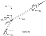
- Fig. 12 shows a nerve stimulation apparatus 10J according to an example embodiment of the invention.
- Apparatus 10J comprises a tubular member 24J.
- Electrode structure 12AJ extends out of the distal end of tubular member 24J whereas electrode 12BJ extends out of an opening 34J on tubular member 24J.
- Electrode structure 12AJ is attached to shaft portion 14J and electrode structure 12B is attached to shaft portion 68J.
- Shaft portions 14J and 68J are both inside tubular member 24J. Electrode structures 12AJ and 12BJ can be independently controlled from outside the body.
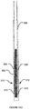
- Fig. 13A shows a nerve stimulation apparatus 10K.
- tubular member 24K has five lumens 32K.
- Figs. 13B-13E show some possible cross sections of tubular member 24K taken at line A-A in Fig. 13A .
- Three lumens 32K may be used for drug infusion and are in fluid communication with openings 62AK, 62BK, 62CK located in a proximal, middle and distal portion of tubular member 24K.
- One lumen contains shaft portion 14K which is coupled to electrode structure 12AK.
- One lumen contains shaft portion 68K which is coupled to electrode structure 12BK.
- each of the five lumens has the same size and has a circular cross section.
- Fig. 13B each of the five lumens has the same size and has a circular cross section.
- the lumens have different sizes, but all have circular cross sections.
- the lumens have different sizes and non-circular cross sections.
- the lumens have different sizes and are a mix of circular and non-circular cross sections.
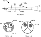
- Fig. 14A is another embodiment of a nerve stimulation apparatus 10L.
- Figs. 14B and 14C show some possible cross sections of tubular member 24L in the Fig. 14A embodiment.
- tubular member 24L has three lumens 32L.
- One lumen 32L contains shaft portion 14L which is coupled to electrode structure 12AL.
- One lumen 32L contains shaft portion 68L which is coupled to electrode structure 12BL.
- One lumens may be used for drug infusion to opening 62L located in a middle portion of tubular member 24L.
- each of the three lumens has the same size and has a circular cross section.
- the lumens have non-circular cross sections.
- Fig. 15 shows a nerve stimulation apparatus 10M.
- Apparatus 10M comprise a tubular member 24M.
- the proximal end of tubular member 24M is coupled to introducer 38M.
- Introducer 38M has a side port 39M.
- Both electrode structures 12AM, 12BM extend out of a distal opening of tubular member 24M.
- Electrode strucutre 12AM is coupled to shaft portion 14M.
- Electrode structure 12BM is coupled to shaft portion 68M. Electrode structures 12AM and 12BM can be independently controlled.
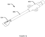
- Fig. 16 shows a nerve stimulation apparatus 10N.
- Nerve stimulation apparatus 10N comprises a tubular member 36N, an electrode structure 12N and a shaft portion 14N (not visible). Electrode structure 12N extends out of a distal opening of tubular member 36N. Shaft portion 14N is inside tubular member 36N.
- Tubular member 36N may be a cannula or catheter-type tubular member. The length of tubular member 36N is sufficiently long to enter the vessel by about 1 cm such that nerve stimulation apparatus 10N is suitable for stimulating the left phrenic nerve when inserted into a patient's LSV and left BCV.
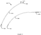
- Fig. 17 shows a nerve stimulation apparatus 10O.
- Nerve stimulation apparatus 10O comprises a tubular member 240, an electrode structure 120 and a shaft portion 140 (not visible). Electrode structure 120 is attached to a distal end of shaft portion 140. Shaft portion 140 is not visible in Fig. 17 because shaft portion 140 is inside tubular member 240.
- Tubular member 240 may be a catheter-type tubular member. The length of tubular member 240 may be 16-20 cm so that nerve stimulation apparatus 10O is suitable for stimulating the right phrenic nerve when inserted into a patient's LSV, left BCV and then enters SVC. It should be noted that apparatus 10N, 10O may be used in combination to stimulate both left and right phrenic nerves at the same time.
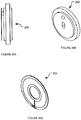
- Figs. 18A, 18B show an electrode structure 12P according to an example embodiment of the invention.
- Fig. 18A is a top plan view of electrode structure 12P.
- Fig. 18B is a bottom perspective view of electrode structure 12P.
- Electrode structure 12P comprises at least one electrode 20P and an insulating pad 42P.
- Pad 42P may be resiliently flexible. When electrode structure 12P is not confined inside a tubular member, pad 42P can automatically spring open to take a desired shape. When electrode structure 12P springs open, electrode structure 12P may have a dimension that is greater than the transverse dimension of the tubular member.
- Electrode 20P may be supported on pad 42P, but this is not mandatory.
- Pad 42P has a petal or leaf-like shape, although pad 42P may be of any other suitable shape.
- Pad 42P may be an insulating pad, thereby insulating electrode 20P from the blood in a blood vessel.
- Pad 42P may be made of an insulating material or materials. Suitable materials for making pad 42P include, without limitation, PTEF, silicone, PET, and nylon.
- Pad 42P may present a high-impedance to the flow of electrical current and therefore reduces the amount of current flowing through the blood when electrode structure 12P is deployed in a blood vessel.
- pad 42P It is not mandatory that pad 42P have an extremely high electrical resistance. It is sufficient if pad 42P has a resistance to the flow of electricity through pad 42P that is significantly greater than that presented by the blood in blood vessel V. Blood typically has a resistivity of about 120 to 190 ⁇ cm.
- the blood in a blood vessel may provide an electrical resistance between closely-spaced electrical contacts that is inversely proportional to the dimensions of the lumen of the blood vessel. In large blood vessels the longitudinal electrical resistance between reasonable closely-spaced contacts can be a few tens of ohms for example.
- Pad 42P preferably provides an electrical resistance of at least a few hundred ohms, preferably a few kilo ohms or more to the flow of electrical current through the thickness of pad 42P.
- Pad 42P could have electrically conductive members such as leads and the like embedded within it or electrically-conductive electrode or other features on its inner surface and still be considered to be 'insulating'.
- electrode 20P may be supported on pad 42P.
- Pad 42P can be rolled up and retracted into the tubular member to facilitate insertion or retrieval of electrode structure 12P within a blood vessel.
- pad 42P can spring open to take a shape that has a curvature that generally conforms to the wall of a blood vessel. This helps to bring electrode 20P which is on a side of pad 42P to be in close proximity of the blood vessel wall. Blood flow in the blood vessel may also assist in deploying electrode structure 12P and pressing pad 42P against the walls of a blood vessel.
- electrode structure 20P does not need to be fixed or fastened to the blood vessel wall, but rather can float inside the blood vessel against the wall.
- electrode structure 12P also comprises a wire 44P which is connected to shaft portion 14P.
- Wire 44P passes through apertures 46P in pad 42P, thereby holding pad 42P in place.
- Wire 44P may provide structural support to pad 42P.
- wire 44P may optionally serve as a ground electrode or a reference electrode.
- a lead 45P extends from a bore in shaft portion 14P to a backside 56P of electrode 20P.
- Lead 45P may be coated with an insulating material (e.g., Teflon TM or other suitable insulating material).
- Sensors such as a thermistor, an oxygen sensor, and/or CO 2 sensor (not shown) may be supported on electrode structure 12P.
- electrode structures 12P may be used for plethysmography.
- electrode 20P is exposed on one side (e.g., the convex side, i.e., the side facing the blood vessel wall) of pad 42P.
- Pad 42P may, for example, comprise a reinforced silicone material.
- pad 42P is a pad of Dacron-mesh-reinforced silicone. This material can be rolled up, has shape memory so that it tends to open up, and is resiliently flexible so that it can conform to the wall of a blood vessel. Blood flow in the blood vessel may also assist in deploying electrode structure 12P and supporting electrode structure 12P against the walls of a blood vessel.
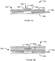
- Fig. 19A shows a schematic of a cross section of an electrode structure 12Q according to one example embodiment of the invention.
- electrode 20Q comprises one or more ribbons 48Q of a suitable biocompatible metal.
- Pad 42Q on which the ribbons 48Q are supported comprises two layers.
- a top layer 50Q which faces the wall of the blood vessel has apertures 52Q and the ribbons 48Q pass through aperture 52Q such that a portion of the ribbons 48Q is exposed and able to contact or be in close proximity of a wall 54Q of the blood vessel.
- the bottom layer 56Q which faces the center of the blood vessel may be made of a suitable insulating material.
- Ribbons 48Q are electrically coupled to lead 45Q which is directly or indirectly coupled to a source of electricity (e.g., a stimulation generator).
- the bottom insulating layer 56Q may comprise a thin material such as Teflon TM , polyurethane, or silicone.
- the material of electrode 20Q is preferably relatively thin so that it does not make the electrode structure too stiff.
- the electrode material may comprise metal ribbons 48Q that are 0.5 to 1 mm wide, or less than 0.5 mm wide.
- the electrodes may comprise areas of conductive polymer printed on or contained in the insulating material of the electrode structure.
- the delivery of electrical stimulation to a target nerve is enhanced by:
- Figs. 20A and 20B are perspective and side views of wire 44P according to one example embodiment.
- Wire 44P is connected to shaft portion 14P.
- Wire 44P may form a hair-pin configuration, extending from shaft portion 14P on one side of pad 42P (not shown in Figs. 20A and 20B ), passing through apertures 46P in pad 42P to the other side of pad 42P and then extending in the opposite direction.
- wire 44P may, for example, be welded or otherwise attached to the stainless steel tube(s).
- Wire 44P may comprise a loop of 0.010 inch stainless steel (for example Elgiloy TM ). The wire of the loop may pass through apertures 46P in the insulating pad 42P on which electrode(s) 20P are supported as shown in Figs. 18A, 18B . This positively retains pad 42P in place.
- Wire 44P may be passed through apertures 46P before being affixed to shaft portion 14P.
- wire 44P provides one of a plurality of electrodes for monitoring bioelectrical activity and/or delivering electrical stimulation.
- Figs. 21A, 21B are top and bottom perspective views of an electrode structure 12R. Electrode structure 12R is similar to electrode structure 12P. In Figs. 21A, 21B , pad 42R is flexible and partially rolled-up, and electrode 20R is located on the convex side of pad 42R.
- Fig. 22 shows an electrode structure 12S according to one example embodiment.
- pad 42S of electrode structure 12S is asymmetrical. This provides better coverage and provides the possibility of placing the electrodes 20S at more discrete locations around a blood vessel while still being able to compactly roll up the electrode structure 12S for insertion and retrieval.
- a plurality of electrodes 20S are provided on electrode structure 12S. Providing a plurality of electrodes 20S on each electrode structure allows selection of an electrode or a combination of electrodes to provide the most effective stimulation of a target nerve.
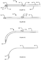
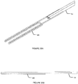
- Figs. 23A-23E show how an example electrode structure 12T may be rolled up and retracted into a tubular member 24T.
- pad 42T of electrode structure 12T is flexible enough that electrode structure 12T can be pulled into tubular member 24T by pulling shaft portion 14T (not visible) which is coupled to electrode structure 12T.
- Figs. 24A-24E show how an example electrode structure 12U may be rolled up, deployed, and retracted into a tubular member 24U.
- electrode structure 12U may initially be fully rolled up inside tubular member 24U (e.g., when nerve stimulation apparatus 10 is being inserted into a patient's blood vessel).
- the two halves of pad 42U of electrode structure 12U may be rolled up in the same direction.
- electrode structure 12U when nerve stimulation apparatus 10 is located in a desired position in the patient's blood vessel, electrode structure 12U may be deployed by moving electrode structure 12U out of tubular member 24U and opening pad 42U. As shown in Figs. 24D and 24E , electrode structure 12U may be retrieved by turning or rotating shaft portion 14U from outside the body to roll up pad 42U. Once pad 42U is rolled up, electrode structure 12U can be retrieved into tubular member 24U. The entire tubular member 24U which contains electrode structure 12U can then be withdrawn from the patient's body.
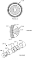
- Fig. 25 and 26 show two example electrode structures 12V, 12W.
- the Fig. 25 electrode structure 12V has a pad 42V that has a gentle curl (in cross section). Electrodes 20V are located on a convex side of pad 42V. Pad 42V comprises a low-stiffness spring wire loop 70V.
- wire loop 70V is in its relaxed, expanded configuration.
- Wire loop 70V may be made of nitinol or stainless steel, for example.
- Wire loop 70V may be located on the side of pad 42V that is facing the center of the blood vessel (e.g., the concave side of pad 42V) and opposite from the side where electrodes 20V are located.
- wire loop 70V may be sandwiched inside a pocket formed by two insulating pad layers of pad 42V. Electrodes 20V are exposed on the side of pad 42V that is facing the wall of the blood vessel (e.g., the convex side of pad 42V). Wire 44V is woven and adhered to pad 42V to provide structural support and stiffness to pad 42V. Electrode structure 12V may be withdrawn into tubular member 24V by pulling on shaft portion 14V from outside the body. On reaching the edge of tubular member 24V, the low stiffness deformable spring wire loop 70V collapses and pad 42V enters tubular member 24V. The tubular member 24V together with electrode structure 12V is then withdrawn from the body.
- the Fig. 26 electrode structure 12W is similar to the Fig. 25 electrode structure 12V except that wire loop 70V is replaced with deformable low-stiffness springy ribs 72W. Electrode structure 12W may be retrieved into tubular member 24 in a similar fashion as electrode structure 12V.
- Figs. 27A-27E schematically illustrate a nerve stimulation apparatus 10X according to another embodiment.
- Fig. 27A shows apparatus 10X coupled to a hub 40X.
- Fig. 27B shows apparatus 10X in position inside left BCV and SVC.
- Apparatus 10X comprises electrode structures 12AX, 12BX (collectively 12X). Electrode structures 12AX, 12BX may be the same or can be of different sizes and/or shapes.
- pad 42X of each electrode structure 12X comprises an inflatable balloon 58X.
- the inflatable balloon 58X may be made of a suitable polymer material (e.g., PET, nylon, silicone).
- the balloon 58X may be compliant, semi-compliant, or non-compliant.
- the balloon 58X may be inflated with a fluid (e.g, saline solution) and, once inflated, will take the desired shape. Electrodes 20X are disposed on one side of pad 42X. Electrodes 20X may be printed or glued on balloon 58X. Apparatus 10X also comprises a conduit for infusing fluid into balloon 58X, and the infusion of fluid into balloon 58X can be controlled from outside the body.
- Fig. 27D shows electrode structure 12X with balloon 58X in a deflated state.
- Fig. 27E shows electrode structure 12X with balloon 58X in a inflated state. Out of the package, balloon 58X is pleated and folded to wrap around shaft portion 14X.
- Balloon 58X is parked inside one of the lumens of apparatus 10X.
- shaft portion 14X is pushed from the proximal end of apparatus 10X; balloon 58X pops out of an opening of tubular member 24X and then is inflated.
- balloon 58X is first deflated and then pulled into one of the lumens of apparatus 10X from the proximal end of apparatus 10X via shaft portion 14X.
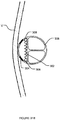
- Figures 28A, 28B show an example method for locating electrode structure 12 in a blood vessel V to a target nerve N.
- electrode structure 12 is inserted into blood vessel V while electrode structure 12 is retracted within tubular member 24.
- Electrode structure 12 is then extended out of tubular member 24 and positioned at location A.
- the amount of electric current required to stimulate nerve N is measured using a suitable device. This may be done, for example, by detecting muscle activity as a result of nerve stimulation, for example, diaphragm muscle activity as result of phrenic nerve stimulation.
- Electrode structure 12 is then retracted into tubular member 24.
- tubular member 24 is advanced in blood vessel V for a small distance (e.g., 0.1 mm, 0.2 mm, 0.5 mm, 1 mm, 2 mm, 5 mm, etc.) and electrode structure 12 is then extended out of tubular member 24 and positioned at Location B. Again, the amount of electric current required to stimulate nerve N is measured using a suitable device. These steps are repeated (e.g. at Location C, Location D, Location E) for as many times as necessary.
- a small distance e.g., 0.1 mm, 0.2 mm, 0.5 mm, 1 mm, 2 mm, 5 mm, etc.
- FIG. 28B shows a schematic graph of such a function.
- the amount of electric current required to stimulate nerve N is the lowest at Location C. Therefore, in this illustration, Location C is a desirable or optimal location to place electrode structure 12 as compared to Locations A, B, D and E.
- This method can be practised either manually or in conjunction with a suitable machine, such as a graphing calculator or a computer.
- One aspect of the invention relates to sensors for sensing and/or monitoring the position of an electrode structure 12 inserted into a blood vessel and associated methods.
- the sensor may be optionally disposable.
- the sensor may be placed outside of the patient's body.
- the sensor may be fixed to the reference frame of the patient's body.
- the sensor acquires positional data and can also relay data to a control unit where electrode position is monitored simultaneously with stimulation parameters and results of stimulation.
- the control unit calculates the best placement of electrodes 20 and can store this information or provide feedback to the therapist in real time or at later times.
- a nerve stimulation system may comprise the following: an intravascular nerve stimulation apparatus having flexible tubular member(s) that can be inserted, advanced, and/or rotated in a blood vessel; one or more sensors that track the position of the intravascular electrodes; and a control unit that acquires position data and relays it to the therapist and/or stores it for later use.
- the sensor is coupled to a proximal part of a shaft portion of the nerve stimulation apparatus. The sensor may be placed outside of the body.
- Fig. 29A schematically shows an example embodiment of a sensor 80A that is independent from an introducer or tubular member of an intravascular nerve stimulation apparatus 10.
- Fig. 29B schematically shows an example embodiment of a sensor 80B that is integrated with an introducer or tubular member of an intravascular nerve stimulation apparatus 10.
- the senor is a pressure-sensitive variable resistance potentiometer sensor.
- a sensor is suitable for monitoring the position (depth) of an intravascular electrode inside a blood vessel.
- the sensor supplies a voltage output signal that is approximately linearly proportional to the position of the electrode.
- Fig. 29C and 29D show an example sensor 80C in cross-sectional and perspective views.
- Sensor 80C comprises a pressure-sensitive linear potentiometer 81.
- a low-friction bead 82C (e.g., a Teflon bead) is fixed onto an elongate shaft portion 14. Potentiometer 81, bead 82, and part of shaft portion 14 are assembled within a guide chamber 84C to form sensor 80C.
- Sensor 80C may be fixed either to the patient, or to the tubular member or the introducer of a nerve stimulation apparatus. As the shaft portion 14 advances, the bead 82 slides along and exerts pressure on potentiometer 81, therefore changing its resistance. The point of contact of the bead 82 against the potentiometer 81 provides a signal that, provided that the shaft portion 14 does not buckle, is generally linearly proportional to the intravascular position of the electrode 20.
- the length of the active region of the potentiometer 81 limits the distance over which the depth of the electrode 20 can be tracked.
- a commercially available flexible potentiometer may be used with a 6 cm long active region which is sufficient to monitor the movement of an electrode in the vicinity of its target phrenic nerve.
- potentiometers of any desired length may be manufactured for this purpose. If shaft portion 14 has a circular cross-section and bead 82 is spherical and coaxial the shaft portion 14, the shaft portion 14 can be rotated while maintaining contact with the potentiometer 81 to obtain the angular positions of the shaft portion 14 and electrode 20.
- Figs. 29F-H show an additional example embodiments of sensor 80D, wherein the guide chamber 84D has a generally triangular cross-section.
- sensor 80 is integrated with the hub of a nerve stimulation apparatus.
- An example sensors 80G is shown in Fig. 29L .
- the depth and the angular position of an intravascular electrode can be monitored by combining the use of a linear potentiometer as described above, plus a circular potentiometer to monitor rotation of the shaft portion.
- the angular position can be controlled by a series of "click stops" placed at convenient angles (e.g., one stop every 15° or 30°) over a desired angular range (e.g., +/- 90° from a central default angular position of an electrode) and a multi-pole electrical switch can be connected to indicate each click stop.
- the shaft portion proximal to the linear transducer can be modified to be of non-circular cross-section, for example square cross-section, and a dial can be incorporated with a square hole through which the shaft portion travels.
- the therapist can manually rotate either the shaft portion itself or its associated dial, and the rotational movement of the dial is sensed by an integrated sensor housed inside the hub of the nerve stimulation apparatus or alternatively by a multi-pole electrical switch with pre-set click stops.
- Fig. 29L shows an embodiment wherein the shaft portions 14 can be rotated by dials.
- Fig. 29M shows an embodiment of a sensor 80H in which the shaft portion 14 is coupled by way of a string or other flexible element to a spring-loaded shaft fitted with a rotational sensor 90.
- the rotational sensor's rotational axis 91 is fitted with a rotational encoder (not shown in Fig. 29M ), which can be converted into a linear displacement measurement.
- the shaft portion 14 is attached to rotational sensor 90 using a collar 92 and a wire 94. As the shaft portion 14 is moved, the collar 92 slides through a guide 96 which prevents the shaft portion 14 from moving in any axis other than the one in which the rotational sensor 90 keeps track of position.
- rotational sensor 90 may be put at an angle by having the wire 94 redirected by a pulley or a block 98.
- the collar 92 can be fitted with a slider or the assembly can allow the user to move the shaft portion 14 directly.
- Fig. 29N and 29O are side and front views of a sensor 80J where the shaft portion 14 is fitted between a roller 100 and a guide 102. As the shaft portion 14 passes the roller 100, it creates a rotational motion of the roller 100 in the same direction. The rotational movement of the roller 100 is then converted to a linear movement through an encoder 104. Both roller 102 and encoder 104 are located co-axially on a rotational axis 106.
- Fig. 29P shows a sensor 80K wherein shaft portion 14 is fitted with a collar 108 made out of an insulating material.
- the collar 108 has at least one conductive ring 110.
- Ring 110 slides through a guide 112 fitted with electrical contacts 114. As the collar 108 slides through the guide 112 and the ring 110 touches the electrical contacts 114 on each side, a current passes through the ring 110.
- the current may be converted to positional data, either by correlating position to resistance or by identifying the shorted contacts and associating them with a calibrated position.
- Fig. 29Q shows a sensor 80L in which a shaft portion 14 is fitted with two resistive traces 116 connected at one end. Both resistive traces 116 are exposed, but the bridge connecting them is not.
- both traces 116 contact two halves of a metallic ring. A current is sent through one half, and received via the other half. The current goes through the traces 116 on the shaft portion 14. The voltage drop measured across the ring halves is proportional to the length of the traces 116 the current goes through. By calibrating the resistance, a position measurement can be obtained.
- Fig. 30A shows an example angle sensor 200 (in side view) in which a lead with a non-circular profile slides through a disc which is free to rotate.
- Angle sensor 200 comprises wiper 202 ( Fig. 30B ) and potentiometer 204 ( Fig. 30C ). When the lead is rotated, the sleeve rotates with the wiper 202 that applies a pressure on cylindrical membrane potentiometer 204.
- Figs. 30D to 30F shows an example angle sensor 208 in which a lead with a non-circular profile slides through a sleeve 210 which is free to rotate.
- Fig. 30D is a cross-sectional view of sensor 208.
- Fig. 30E is a side view of sensor 208.
- Fig. 30F is an exploded view of sensor 208.
- Sensor 208 comprises sleeve 210 with wiper 211, conductive membrane 212, space layers 214, resistive trace 216 and support structure 218.
- Figs. 30G and 30H show an angle senor 220 in which a lead with non-circular profile slides through a sleeve which is free to rotate.
- Sensor 220 comprises sleeve 222 having a conductive strip 224, a flexible PCB 226, and a support structure 228.
- the flexible PCB 226 comprises electrical contacts 234, measurement traces 232, and a perpendicular trace 230.
- the sleeve 222 rotates and creates an electrical contact with a cylindrical board with multiple contacts.
- This part may be a flexible PCB 226 with a series of parallel exposed traces 232 and one perpendicular trace 230.
- the perpendicular trace is then energized and shorted with one of the other traces via a conductive strip on the rotating sleeve.
- a control unit then cycles through the contacts and looks for the traces that are energized to find the position.
- the conductive part shorting the traces can be shorting only the energized trace with another, or more than one. For example, the conductive part could short all traces but one, so that the control unit would look for the trace that is not energized.
- Figs. 31A-31D show a "cobra hood" expandable design which may be used in combination with the electrode structure of the nerve stimulating apparatus described herein as well as in other contexts. Such a design may be used, for example, to provide a backing member (e.g., petal) for one or more electrodes. For example, such a structure may be deployed to stimulate the left phrenic nerve.
- Fig. 31B is a schematic cross-sectional view of the cobra design wherein an expandable shroud 302 is in an unexpanded configuration.
- Fig. 31C is a schematic cross-sectional view of the cobra design wherein shroud 302 is in an expanded configuration.
- Fig. 31D is a schematic plan view of the cobra design wherein shroud 302 is in an unexpanded configuration.
- Fig. 31E is a schematic plan view of the cobra design wherein shroud 302 is in an expanded configuration.
- Shroud 302 comprises a panel of material.
- the material is electrically insulating. In some embodiments the material is elastically stretchable.
- shroud 302 is configured to be stored inside a tubular member 306 in an unexpanded configuration.
- One or more electrodes 304 may be located above or on top of shroud 302, oriented towards an inner surface of a blood vessel V.
- Shroud 302 may be connected to and/or supported by a pair of flexible members such as rods or tubes 308 which run inside tubular member 306 when shroud 302 is not deployed.
- the flexible members may be resiliently flexible.
- Rods or tubes 308 may be made of stainless steel, Nitinol, or some other suitable material, for example.
- the distal ends of rods or tubes 308 may be anchored or fixed to tubular member 306 at anchor positions 310. In alternative embodiments, distal ends of rods or tubes 308 may move freely to some extent along the tubular member 306.
- Tubular member 306 comprises side openings 312.
- Shroud 302 can be manipulated from outside the body to move between a collapsed configuration and an expanded configuration.
- a user pushes the proximal ends of rods or tubes 308 towards the distal ends, portions of rods or tubes 308 along side openings 312 bulge out and extend out of side openings 312 of tubular member 306. This in turn stretches shroud 302 to open to an expanded configuration.
- shroud 302 When shroud 302 is expanded, it forms a petal-like backing member for electrodes 304.
- Shroud 304 may help to position electrodes 304 against the blood vessel wall.
- the electrically insulating shroud also functions as an electrically insulating backing sheet which helps to insulate electrodes 304 from the blood flowing in the lumen of the blood vessel.
- the "cobra" design shown in Figs. 31A-31E may be altered to produce a "half cobra" design.
- one edge of shroud 302 is connected to and/or supported by a rod or tube 308; the other edge of shroud 302 is fixed inside tubular member 306 (e.g., fixed to an inside surface of tubular member 306).
- rod or tube 308 is manipulated to bulge out, shroud 302 expands to one side to form a "half cobra" backing sheet in an expanded configuration.
- a device may comprise two "half cobra” shrouds side by side which together form a "full-cobra” backing sheet in operation.
- Electrodes 304 could be located on tubular member 306. Instead of or in addition to electrodes 304 on tubular member 306, electrodes 304 could be on shroud 302. Where flexible members 308 are electrically conductive, portions of flexible member 308 may be exposed to provide electrodes.
- the applications of the apparatus and methods described herein are not limited to phrenic nerves.
- the apparatus and methods described herein may be applied to provide surgically simple, low risk solutions for stimulating a wide range of peripheral or cranial nerves.
- the methods and apparatus may be applied to stimulate the obturator nerve in the hip/groin area or the trigeminal nerve in the head.
- the apparatus and methods may be applied to treatment of a wide variety of disorders such as pain of peripheral or craniofacial origin, sensory deficits, paralysis or paresis of central origin, autonomic disorders, and generally any medical condition that can be treated or alleviated using neuromodulation by electrical stimulation of a nerve that is in close proximity to a blood vessel into which a nerve stimulation apparatus can be deployed.
- disorders such as pain of peripheral or craniofacial origin, sensory deficits, paralysis or paresis of central origin, autonomic disorders, and generally any medical condition that can be treated or alleviated using neuromodulation by electrical stimulation of a nerve that is in close proximity to a blood vessel into which a nerve stimulation apparatus can be deployed.
Abstract
Description
- This application claims priority from United States Application No.
61/606,899 filed 5 March 2012 61/606,899 filed 5 March 2012 - The invention relates to neurophysiology and in particular to apparatus and methods for stimulating nerves through the walls of blood vessels. Non-limiting embodiments include nerve stimulation apparatus, electrode structures, electrodes and related methods.
- Nerve stimulation can be applied in the treatment of a range of conditions. Nerve stimulation may be applied to control muscle activity or to generate sensory signals. Nerves may be stimulated by surgically implanting electrodes in or near the nerves and driving the electrodes from an implanted or external source of electricity.
- The phrenic nerves nominally carry signals that cause the contractions of the diaphragm that arc necessary for breathing. Various conditions can prevent appropriate signals from being delivered to the phrenic nerves. These include:
- chronic or acute injury to the spinal cord or brain stem;
- Amyotrophic Lateral Sclerosis (ALS);
- disease affecting the spinal cord or brain stem; and,
- decreased day or night ventilatory drive (e.g. central sleep apnea, Ondine's curse).
- Mechanical ventilation (MV) may be used to help patients breathe. Some patients require chronic mechanical ventilation and many more patients require temporary mechanical ventilation. Mechanical ventilation can be lifesaving but has a range of significant problems and/or side effects. Mechanical ventilation:
- tends to provide insufficient venting of the lungs. This can lead to accumulation of fluid in the lungs and susceptibility to infection and pneumonia..
- requires apparatus that is not readily portable.
- can adversely affect venous return because the lungs are positively pressurized.
- interferes with eating and speaking.
- requires costly maintenance and disposables.
- tends to cause positive pressure ventilator induced lung injury (VILI) and ventilator associated pneumonia (VAP).
- A patient on mechanical ventilation is tied to a ventilator, and does not breathe independently. This can lead to atrophy of the diaphragm muscle (ventilator induced diaphragmatic dysfunction; VIDD) and an overall decline in well being. Muscle atrophy can occur surprisingly rapidly and can be a serious problem. In patients on mechanical ventilation, the central respiratory drive of the diaphragm is suppressed. The inactivity of the diaphragm muscle causes rapid disuse atrophy. According to a published study (Levine et al., New England Journal of Medicine, 358: 1327-1335, 2008), the diaphragm muscle could shrink by 52-57% after just 18-69 hours of mechanical ventilation and sedation. Ventilator-induced diaphragm atrophy could cause a patient to become ventilator-dependent. Patients in intensive care units (ICU) who become dependent on mechanical ventilation (MV) are at high risk of complications such as ventilator-acquired pneumonia (VAP) and nosocomial infections and are seven times more likely to die in the ICU. It has been reported that in 2008, 1.58 million ICU patients in the United States require MV every year, of which 20-30% (about 400,000 mechanically ventilated patients) have difficulty weaning from MV and are at risk of becoming ventilator-dependent.
- Three methods have been used to reverse or slow down atrophy in disused diaphragm muscles by stimulating the phrenic nerves and are discussed below.
- Method 1. Phrenic nerve pacing uses electrodes implanted in the chest to directly stimulate the phrenic nerves. The Mark IV Breathing Pacemaker System available from Avery Biomedical Devices, Inc. of Commack, New York, USA, is a diaphragmatic or phrenic nerve stimulator that has surgically implanted receivers and electrodes mated to an external transmitter by antennas worn over the implanted receivers. Implanting electrodes and other implantable components for phrenic nerve pacing requires significant surgery. The surgery is risky and complicated by the fact that phrenic nerves are thin (approximately 2 mm in diameter) and delicate. The surgery involves significant cost.
- Method 2. Laproscopic diaphragm pacing developed by biomedical engineers and physician researchers at Case Western Reserve University is another technique for controlling breathing. Laproscopic diaphragm pacing involves placing electrodes at motor points of the diaphragm.
- Method 3. A method using intravascularly implanted electrodes to stimulate a nerve has been developed by Joaquin Andres Hoffer and is described in
US Patent Application No. 12/524,571 (published on February 11, 2010 US2010/00336451 - Method 3 has advantages over Methods 1 and 2, because it does not require invasive surgery that would typically be performed under full anaesthesia. Furthermore, ICU patients are not typically eligible for Methods 1 and 2.
- There remains a need for cost-effective, practical, surgically simple and minimally invasive apparatus and methods for nerve stimulation. There is also a need for apparatus and methods for facilitating patients on MV to breathe more naturally and to be weaned from MV. There is also a need for cost effective, practical apparatus and methods for installing and/or removing nerve stimulation apparatus.
- This invention has a number of aspects. Aspects of the invention include: designs for intravascular electrodes; electrode structures; nerve stimulation apparatus; intravascular apparatus including electrodes and structures for introducing and supporting the electrodes; catheters equipped with electrodes; methods for nerve stimulation; and methods for measuring the location of an electrode structure within a blood vessel relative to a target nerve. While these and other aspects may be applied together, individual aspects may be applied separately as well as in other combinations and contexts. For example, electrode structures as described herein may be applied in combination with various deployment systems known in the art for various diagnostic and/or therapeutic applications.
- Aspects of the invention may be applied for restoring breathing, treating conditions such as muscle atrophy, chronic pain, and other uses involving nerve stimulation. Aspects of the invention may be applied in the treatment of acute or chronic conditions. Aspects of the invention may be applied to conveniently deploy and remove electrode structures in a patient.
- One aspect of the invention relates to transvascular stimulation of nerves. In transvascular stimulation, suitable arrangements of one or more electrodes are positioned in a blood vessel that passes close to a nerve to be stimulated. Electrical currents pass from the electrodes through a wall of the blood vessel to stimulate the target nerve.
- One aspect of the invention relates to transvascular stimulation of nerves in the neck and chest of a human or other mammals (e.g., a pig).
Figures 1A illustrates the anatomy of selected nerves and blood vessels in the neck and chest of a human and, in particular, the relative locations of the left and right phrenic nerves (PhN), vagus nerves (VN), internal jugular veins (IJV), brachiocephalic veins (BCV), superior vena cava (SVC) and left subclavian vein (LSV). - Further aspects of the invention and features of example embodiments are illustrated in the appended drawings and/or described in the text of this specification and/or described in the accompanying claims.
- The accompanying drawings illustrate non-limiting example embodiments of the invention.
-
Figure 1A illustrates the anatomy of selected nerves and blood vessels in a person's neck and upper torso. -
Figs. 2A-2D are schematic views of a nerve stimulation apparatus according to an example embodiment of the invention. -
Figs. 3A-3C illustrate the operation of nerve stimulation apparatus. -
Fig. 4A illustrates a shaft portion comprising a pair of attached tubes. -
Fig. 4B illustrates a shaft portion comprising telescoping tubes. -
Figs. 5A and 5B are schematic views of a nerve stimulation apparatus according to an example embodiment of the invention. -
Figs. 6A and 6B are schematic views of a nerve stimulation apparatus according to another example embodiment of the invention. -
Figs. 7A and 7B are schematic views of a nerve stimulation apparatus according to another example embodiment of the invention. -
Fig. 8 schematically shows a nerve stimulation apparatus according to another example embodiment of the invention. -
Fig. 9 schematically shows a nerve stimulation apparatus according to another example embodiment of the invention. -
Fig. 10A is a side view of a nerve stimulation apparatus according to another example embodiment of the invention.Fig. 10B is an isometric view of the apparatus ofFig. 10A in combination with an introducer and a hub.Figs. 10C and 10D are examples of alternative cross-sectional views of the apparatus ofFig. 10A . -
Figs. 11A and 11B show a nerve stimulation apparatus in combination with an introducer and a hub according to an example embodiment of the invention.Figs. 11C and 11D are cross sectional views of nerve stimulation apparatus along lines B-B and A-A respectively shown inFig. 11B . -
Fig. 12 shows a nerve stimulation apparatus according to an example embodiment of the invention. -
Fig. 13A shows a nerve stimulation apparatus according to an example embodiment of the invention that provides a five-lumen catheter.Figs. 13B-13E show some possible cross sections of the apparatus ofFig. 13A taken at line A-A inFig. 13A . -
Fig. 14A shows another embodiment of a nerve stimulation apparatus.Figs. 14B and 14C show some possible cross sections of a tubular member of the apparatus ofFig. 14A . -
Fig. 15 shows a nerve stimulation apparatus. -
Fig. 16 shows a nerve stimulation apparatus. -
Fig. 17 shows a nerve stimulation apparatus. -
Figs. 18A, 18B show an electrode structure according to an example embodiment of the invention.Fig. 18A is a top plan view of the electrode structure.Fig. 18B is a bottom perspective view of the electrode structure. -
Fig. 19A shows a schematic of a cross section of an electrode structure according to one example embodiment of the invention.Fig. 19B shows details electrodes of the electrode structure ofFig. 19A . -
Figs. 20A and 20B are perspective and side views of an electrode retaining wire according to one example embodiment. -
Figs. 21A, 21B are top and bottom perspective views of an electrode structure. -
Fig. 22 shows an electrode structure according to one example embodiment. -
Figs. 23A-23E show how an example electrode structure may be rolled up and retracted into a tubular member. -
Figs. 24A-24E show how an example electrode structure may be rolled up, deployed, and retracted into a tubular member. -
Fig. 25 and 26 show two example electrode structures. -
Figs. 27A-27E schematically illustrate a nerve stimulation apparatus according to another embodiment. -
Figures 28A, 28B show an example method for locating an electrode structure in a blood vessel V to stimulate a target nerve. -
Figs. 29A to 30H shows various sensors which may be used with the nerve stimulation apparatus described herein as well as in other contexts. -
Figs. 31A to 31E shows an example shroud design which may be used with the nerve stimulation apparatus described herein as well as in other contexts. - Throughout the following description, specific details are set forth in order to provide a more thorough understanding of the invention. However, the invention may be practiced without these particulars. In other instances, well-known elements have not been shown or described in detail to avoid unnecessarily obscuring the invention. Accordingly, the specification and drawings are to be regarded in an illustrative, rather than restrictive.
- Apparatus according to some embodiments provides intravascular electrode systems which include one or more electrodes supported on an elongated resiliently flexible support member. The support member may be used to introduce the electrodes into a blood vessel. As the support member is introduced into the blood vessel the support member bends to follow the path of the blood vessel. Restoring forces resulting from the resilience of the support member hold the one or more electrodes in place against the wall of the blood vessel. The electrode structure may comprise flexible electrically insulating pads that insulate electrodes from being in direct contact with blood in the main passage of the blood vessel.
- In some embodiments the apparatus includes two or more electrodes at spaced-apart locations along the support member. Spacing between the electrodes may be selected to allow the electrodes to be located proximate to anatomical structures, for example nerves passing nearby the blood vessel. In an example embodiment, electrodes are spaced apart on a support structure and oriented so that an intravascular electrode system may be placed with electrodes located to stimulate a patient's left and right phrenic nerves. The electrodes may optionally have different circumferential orientations with respect to a longitudinal centerline of the support structure.
- In some embodiments the support member is more flexible in one direction than in another. This can help to preserve a desired orientation of electrodes while the electrode system is being introduced into a blood vessel.
- In some embodiments the electrode system comprises a catheter having one or more lumens. The catheter may provide the functionality of a central catheter of the type commonly used in intensive care units, for example. Such embodiments provide the advantage of electrodes that may be applied, for example, for stimulating nerves (e.g. for diaphragm pacing) and/or for monitoring electrical activity in the body of a patient in the same package as a central catheter that may be required in any event. In some embodiments, the catheter also serves as a support structure as described above.
- Some embodiments comprise electrode structures comprising electrodes and asymmetrical electrically-insulating backing sheets. The backing sheets can electrically isolate the electrodes from blood in the lumen of a blood vessel, thereby allowing more efficient stimulation of extravascular structures such as nearby nerves. The asymmetrical arrangement of the backing sheet allows the backing sheet to be rolled into a compact configuration for insertion of the electrode structure into a blood vessel while providing a backing sheet that can provide electrical insulation for two or more electrodes. In some embodiments the backing sheet has a generally trapezoidal configuration. The backing sheet may be formed so that it tends to unroll from the rolled configuration. The backing sheet may be formed with a natural curvature similar to that of a wall of a blood vessel against which the backing sheet will be deployed. The backing sheet may be but need not be completely electrically insulating. Such a backing sheet can be advantageous as long as it provides a resistance to the flow of electricity substantially greater than the resistance that would be provided by blood in the blood vessel in the absence of the backing sheet. Such electrode structures may be applied in a wide range of intravascular applications.
- Some embodiments provide electrode structures that include a retainer that holds a backing sheet in place. The retainer may comprise, for example, a formed piece of wire that extends through apertures in the backing sheet. In some embodiments the retainer comprises a pair of wire sections, which may be generally parallel, that are each woven through apertures in the backing sheet. Distal ends of the wire sections may be joined. The wire sections may be parts of a continuous wire. Distal ends of the wire sections may be bent back over the backing sheet. In some embodiments the retainer is electrically conductive and may be applied as one electrode, for example a reference electrode for electrical measurements and/or one of two or more electrodes for delivery of stimulation. The backing sheet may be rolled around the retainer for introduction into a blood vessel. Such electrode structures may be applied in a wide range of applications.
- Some embodiments provide electrode structures in which a backing sheet for one or more electrodes is provided by a wall of an inflatable structure. The structure may be inflated to hold the electrodes against a wall of a blood vessel. The structure may, for example, be located on a side of a catheter or other support member. In some embodiments, inflation of the inflatable structure actuates a backing member carrying one or more electrodes to move toward engagement with a wall of a blood vessel.
- Some embodiments provide intravascular electrode structures on which one or more electrodes is supported on a support member which include integrated position-measurement transducers for measuring a displacement of an electrode along a blood vessel into which the electrode is being inserted. The apparatus, including the position-measurement transducers may be intended to be disposable after a single use. Various embodiments of example position measurement transducers that can provide accurate position measurement in a suitable form factor and/or may be fabricated inexpensively are described below.
- The following description describes examples of nerve stimulation apparatus and components suitable for application in nerve stimulation. In some cases the examples given are adapted for stimulation of phrenic nerves in a human or other mammals. The nerve stimulation apparatus described herein has a number of features which are particularly advantageous in combination with one another but can also be used individually, in other combinations, or in combination with the features described in
US2010/00336451 -
Figs. 2A-2C are schematics of anerve stimulation apparatus 10 according to an example embodiment of the invention.Nerve stimulation apparatus 10 compriseselectrode structures Nerve stimulation apparatus 10 also comprises atubular member 24.Tubular member 24 may be a catheter or cannula-type tubular member. For example,tubular member 24 may be a central venous catheter.Tubular member 24 is capable of being inserted into a lumen of a blood vessel. -
Tubular member 24 has adistal end 26, aproximal end 28, an outer wall orsheath 30 that extends fromdistal end 26 toproximal end 28.Tubular member 24 may comprise one or more internal lumens (not specifically indicated inFigs. 2A-2C - examples of such lumens are shown in other Figs.) For example,tubular member 24 may be a multi-lumen catheter. - In the example embodiment, at least one lumen extends longitudinally from
proximal end 28 todistal end 26. The lumens may have exit openings onwall 30 oftubular member 24. These openings may be spaced apart along the length oftubular member 24. The lumens may be used for removing blood samples, inserting medication, delivering fluids or nutrients, measuring chemical or physical parameters in blood, such as pH or temperature, and the like. For example, agents may be applied through one or more of the openings to prevent clot formation onelectrode structures 12. InFig. 2A , anexample opening 34 is shown, which provides an exit port forelectrode structure 12B.Opening 34 may be upstream fromelectrode structure 12B relative to a direction of blood flow in a blood vessel in whichnerve stimulation apparatus 10 is deployed. -
Tubular member 24 may be flexible. A range of materials may be used for construction oftubular member 24, including silicone, polyurethane, or other suitable polymers, stainless steel, and the like.Tubular member 24 may have markings for length determination. In some embodiments,tubular member 24 is more flexible in one bending direction than in another bending direction. In some embodiments, different sections oftubular member 24 have different levels of flexibility. For example, the distal part oftubular member 24 may be more flexible than the proximal part oftubular member 24. -
Electrode structure 12A is positioned at or neardistal end 26 oftubular member 24.Electrode structure 12B is positioned at a mid-portion oftubular member 24.Electrode structures electrode structures electrode structures Fig. 2A ). Whenelectrode structure electrode structure 12A extends out of a distal opening oftubular member 24, andelectrode structure 12B extends out oftubular member 24 from anopening 34 on wall 30 (Figs. 2B and 2C ). Typically,electrode structure 12 is dimensioned so that, when in a deployed position inside a blood vessel, it will extend approximately 45° to 60° of the way around a wall of the blood vessel, although this is not mandatory. - In
Figs. 2A-2C , arepresentative electrode 20 is shown for eachelectrode structure 12. However, it should be noted that eachelectrode structure 12 may comprise a plurality of electrodes. For example, one or more electrodes may be used for stimulating a target nerve; and one or more additional electrodes may be used for ECG monitoring. In some embodiments, one electrode may function as a cathode and another electrode may function as an anode.Electrode structure 20 also comprises an insulatingpad 42. - Each
electrode structure 12 may be coupled to an elongatedflexible shaft portion 14 which extends insidetubular member 24.Shaft portion 14 is not directly visible inFigs. 2A-2C , butFig. 2D schematically shows ashaft portion 14 coupled toelectrode 12A, withouttubular member 24. InFig. 2D , elongatedflexible shaft portion 14 has adistal end 16 and aproximal end 18.Electrode structure 12A is coupled todistal end 16 ofshaft portion 14.Shaft portion 14 may comprise, for example, a single wire or tube or a plurality of wires or tubes.Shaft portion 14 may comprise one or more suitable leads (not specifically indicated inFig. 2D , as leads may be hidden inside shaft portion 14) which may electrically couple one ormore electrodes 20 to an apparatus for monitoring electrical activity and/or delivering electrical stimulation by way ofelectrodes 20. The leads and theelectrodes 20 may be electrically coupled in a one-to-one relationship such that eachelectrode 20 is individually addressable. In some embodiments, some groups of two ormore electrodes 20 are connected to a common lead. The leads may be carried in or alongshaft portion 14. - At equilibrium,
shaft portion 14 may have a configuration that is straight or curved.Shaft portion 14 may have an initial radius of curvature greater than a radius of curvature of the left brachiocephalic vein (BCV) and superior vena cava (SVC) into whichnerve stimulation apparatus 10 may be introduced.Shaft portion 14 may be resilient and tending to return to its original configuration; thus,distal end 16 ofshaft portion 14 tends to spring toward the far wall of the superior vena cava (SVC) whennerve stimulation apparatus 10 is inserted in a patient from the left side of the body (e.g., from LSV into BCV and SVC). This is convenient because the right phrenic nerve typically runs alongside the far wall of the superior vena cava (SVC) at this point. - In some embodiments,
shaft portion 14 is more flexible in one direction than in another direction. For example,shaft portion 14 may be oriented such that it is easier to bend downwardly than sideways. This facilitates insertion and positioning ofshaft portion 14 in SVC which extends downwardly from the BCV. - In some embodiments, different parts of
shaft portion 14 have different levels of flexibility. For example, the distal part ofshaft portion 14 may be more flexible than the proximal part ofshaft portion 14. In some embodiments, flexibility of the shaft portion may vary along the length of the shaft portion.Shaft portion 14 may be made of stainless steel or other suitable material (e.g., Nitinol, high-density plastics, elastomers etc.). In someembodiments shaft portion 14 comprises a pair of flexible stainless steel tubes that are attached together by, for example, welding. - The operation of
nerve stimulation apparatus 10 is schematically shown inFigs. 3A-3C .Nerve stimulation apparatus 10 may be inserted into a person's subclavian vein and SVC as follows. Theelectrode structures tubular member 24. A percutaneous puncture is made into the patient's LSV.Tubular member 24 is then inserted through the puncture into the LSV. Such insertion could be done under local anaesthesia. General anaesthesia is typically not required.Tubular member 24 ofnerve stimulation apparatus 10 is then advanced into the patient's left BCV and eventually into SVC. Care should be taken not to advancetubular member 24 into the right atrium of the heart. When the distal portion oftubular member 24 reaches the SVC, the distal portion oftubular member 24 bends downwardly.Electrode structures Fig. 3B ) to a deployed position (Fig. 3C ).Electrode structures - In the deployed position,
electrode structures tubular member 24.Electrodes 20 are pressed against a wall of the blood vessel, whereas the insulatingpads 42 of theelectrode structures electrodes 20 from being in close electrical contact with the bulk of the blood flowing through the blood vessel. The curvature ofnerve stimulation apparatus 10 may conform to the curvature of the patient's left BCV and SVC. The twoelectrode structures nerve stimulation apparatus 10, withelectrode structure 12A oriented toward the right phrenic nerve andelectrode structure 12B oriented toward the left phrenic nerve. - Testing may be done to locate
electrode structures Figs. 28A, 28B ). Measurements can also be made to determine which electrode or electrodes of an electrode structure comprising multiple electrodes most effectively stimulate the target nerve. - Once
nerve stimulation apparatus 10 has been properly inserted into a patient as described above,electrodes 20 are electrically coupled to a stimulation device (e.g., a pulse generator which may be optionally located outside the body) to apply electric current to the phrenic nerves, causing the diaphragm muscle to contract. The contraction of the diaphragm muscle causes inhalation of air into the lungs. When the electric stimulation of the phrenic nerves is stopped, the diaphragm muscle relaxes and exhalation occurs. This allows the patient to breathe more naturally.Nerve stimulation apparatus 10 may be used in combination with a control unit (e.g., a bedside control unit). -
Nerve stimulation apparatus 10 may be removed from the patient's body. During removal,electrode structures Fig. 3C ) to a retracted configuration (Fig. 3B ). Once theelectrode structures tubular member 24, the entirenerve stimulation apparatus 10 may be withdrawn from the patient's body. Alternatively, removing may not require retraction of electrode structure into the tubular member. Preferred methods for retrievingnerve stimulation apparatus 10 from the patient's body have a number of advantages which include one or more of: (1)nerve stimulation apparatus 10 can be repositioned easily for replacement or if the electrode moves with respect to target nerves, for example while the patient is being moved or transferred; (2) periodic removal of nerve stimulation apparatus prevents the build-up of plaques, or inflammation, or other undesirable physiological or pathological consequences as a result of implanting nerve stimulation apparatus in a blood vessel; (3)nerve stimulation apparatus 10 can be conveniently removed from the patient when nerve stimulation treatment is no longer needed. -
Shaft portion 14 may take a number of different configurations. In the embodiment shown inFig. 4A , ashaft portion 14A comprises a pair of tubes 14A1, 14A2 that are joined together in parallel. Tubes 14A1, 14A2 may be welded or affixed in another suitable manner together at certain spaced apart points or continuously along their length. Tubes 14A1, 14A2 may be made of stainless steel or other suitable material. The two-tube configuration inFig. 4A allowsshaft portion 14A to bend more easily in a plane extending between the two tubes than in a plane of the two tubes. - In the embodiment shown in
Fig. 4B , ashaft portion 14B comprises a pair of tubes 14B1, 14B2 that are coupled together in a concentric fashion. Tube 14B1 has a smaller diameter than tube 14B2 and is insertable and movable in tube 14B2. Tube 14B1 is distal to tube 14B2. Tube 14B1 may be more flexible than tube 14B2. -
Figs. 5A and 5B are schematic views of anerve stimulation apparatus 10C according to an example embodiment of the invention (in a deployed configuration and a retracted configuration respectively). In theFigs. 5A and 5B embodiment, electrode structure 12AC is coupled to a distal end ofshaft portion 14C, and electrode structure 12BC is coupled to a mid-portion ofshaft portion 14C. The coupling betweenelectrode structure 12B andshaft portion 14C may comprise aspring mechanism 35C. Electrode structure 12AC is retractable and extendable through a distal opening oftubular member 24C. Electrode structure 12BC is retractable and extendable through aside opening 34C oftubular member 24C. -
Figs. 6A and 6B are schematic views of anerve stimulation apparatus 10D according to another example embodiment of the invention. In the embodiment shown inFigs. 6A and 6B ,nerve stimulation apparatus 10D comprises afirst tubular member 24D and asecond tubular member 36D. Electrode structure 12AD is coupled to a distal end ofshaft portion 14D. However, electrode structure 12BD is disposed on firsttubular member 24D. Also, firsttubular member 24D passes through secondtubular member 36D and electrode structure 12BD is retractable into secondtubular member 36D. First and secondtubular members Second tubular member 36D has a diameter greater than the diameter of firsttubular member 24D.Second tubular member 36D is typically shorter than firsttubular member 24D. The position of electrode structures 12AD, 12BD may be controlled independently from one another viashaft portion 14D andtubular member 24D respectively. -
Figs. 7A and 7B are schematic views of anerve stimulation apparatus 10E according to another example embodiment of the invention. In theFigs. 7A and 7B embodiment, electrode structure 12AE is coupled to a shaft portion 14E1, and electrode structure 12BE is disposed on a shaft portion 14E2 which is separate from shaft portion 14E1. Shaft portion 14E2 may be structurally different from shaft portion 14E1. Shaft portions 14E1, 14E2 may be independently controlled to deploy or retract electrode structures 12AE, 12BE, respectively. Also, firsttubular member 24E passes through a secondtubular member 36E. Electrode structure 12AE is retractable into firsttubular member 24E. Electrode structure 12BE is retractable into secondtubular member 36E. Secondtubular member 36E has a diameter greater than the diameter of firsttubular member 24E. Secondtubular member 36E is typically shorter than firsttubular member 24E. -
Fig. 8 schematically shows anerve stimulation apparatus 10F according to another example embodiment of the invention. In theFig. 8 embodiment, electrode structure 12AF is coupled to a shaft portion 14F1, and electrode structure 12BF is disposed on a shaft portion 14F2 which is separate from shaft portion 14F1. Shaft portion 14F2 may be structurally different from shaft portion 14F1. Shaft portions 14F1, 14F2 may be independently controlled to deploy or retract electrode structures 12AF, 12BF, respectively.Tubular member 24F comprises asingle lumen 32F. Both shaft portions 14F1 and 14F2 extend insidelumen 32F. Electrode structure 12AF may extend out of a distal opening oflumen 32F. Electrode structure 12BF may extend out of aside opening 34F oftubular member 24F. -
Fig. 9 schematically shows anerve stimulation apparatus 10G according to another example embodiment of the invention.Apparatus 10G is similar toapparatus 10F except thattubular member 24G ofapparatus 10G comprises two lumens 32G1 and 32G2. The two lumens 32G1 and 32G2 are separated by apartition 33G. Shaft portion 14G1 extends in lumen 32G1 and electrode structure 12AG extends out of a distal opening of lumen 32G1. Shaft portion 14G2 extends in lumen 32G2 and electrode structure 12BG extends out of aside opening 34G of lumen 32G2. -
Fig. 10A is a side view of anerve stimulation apparatus 10H according to an example embodiment of the invention.Fig. 10B is an isometric view ofapparatus 10H in combination with anintroducer 38H and ahub 40H.Figs. 10C, 10D are possible cross-sectional views ofapparatus 10H.Nerve stimulation apparatus 10H comprises electrode structures 12AH, 12BH, and atubular member 24H. -
Nerve stimulation apparatus 10H may be coupled to anintroducer 38H and ahub 40H. This may be done during use to facilitate entry of the nerve stimulation apparatus into a patient's blood vessel. It should be noted that other types of introducers and/or hubs different from the ones shown inFig. 10B may also be used in conjunction withnerve stimulation apparatus 10H. Electrode structure 12AH is connected to ashaft portion 14H which extends insidetubular member 24H. Electrode structure 12BH is disposed on firsttubular member 24H. The distance between electrode structure 12AH and 12BH may be in the range of 5-10 cm for example. The distance between electrode structure 12BH and the distal end ofintroducer 38H may be in the range of 0-5 cm for example. -
Tubular member 24H is partially received intubular member 36H ofintroducer 38H. Whennerve stimulation apparatus 10H is applied to a patient,hub 40H and the wing portion ofintroducer 38H stay outside of the patient.Introducer 38H and/orhub 40H may comprise holes for suture. In their deployed configuration, electrode structures 12AH and 12BH have a transverse dimension that is greater than the transverse dimension oftubular member 24H.Apparatus 10H comprises athermistor 64H or other temperature sensor. -
Tubular member 24H may comprise a multi-lumen catheter.Figs. 10C, 10D show possible cross sections oftubular member 24H.Tubular member 24H may have 1, 2, 3, 4, 5, ormore lumens 32H.Shaft portion 14H and leads 45H may run inside one or more of thelumens 32H.Leads 45H may also run inside the bore ofshaft portion 14H. -
Figs. 11A and 11B show anerve stimulation apparatus 101 in combination with an introducer 38I and a hub 40I according to an example embodiment of the invention.Figs. 11C and 11D are cross sectional views ofnerve stimulation apparatus 10 along lines B-B and A-A respectively inFig. 11B . Nerve stimulation apparatus 10I comprises a first tubular member 24I, a second tubular member 36I, an introducer 38I, a hub 40I, a first electrode structure 12AI, a second electrode structure 12BI, afirst shaft portion 14I (not visible) and asecond shaft portion 68I (not visible). Electrode structure 12AI is attached to a distal end offirst shaft portion 14I.First shaft portion 14I is visible inFigs. 11C and 11D (in cross section). Electrode structure 12AI is retractable into the distal end of tubular member 24I. Electrode structure 12BI is attached to second shaft portion 681. Electrode structure 12BI is extendable out of the distal end of second tubular member 36I and is retractable into the distal end oftubular member 361. Second shaft portion 681 is visible inFig. 11C (in cross section). First tubular member 24I is longer than second tubular member 36I and passes through second tubular member 36I. First tubular member 24I comprises a plurality oflumens 32I, and second tubular member 36I surrounds the multi-lumen firsttubular member 241. Because electrode 12AI and 12BI are attached to twoseparate shaft portions -
Fig. 12 shows anerve stimulation apparatus 10J according to an example embodiment of the invention.Apparatus 10J comprises atubular member 24J. Electrode structure 12AJ extends out of the distal end oftubular member 24J whereas electrode 12BJ extends out of anopening 34J ontubular member 24J. Electrode structure 12AJ is attached toshaft portion 14J andelectrode structure 12B is attached toshaft portion 68J.Shaft portions tubular member 24J. Electrode structures 12AJ and 12BJ can be independently controlled from outside the body. -
Fig. 13A shows anerve stimulation apparatus 10K. In this embodiment,tubular member 24K has fivelumens 32K.Figs. 13B-13E show some possible cross sections oftubular member 24K taken at line A-A inFig. 13A . Threelumens 32K may be used for drug infusion and are in fluid communication with openings 62AK, 62BK, 62CK located in a proximal, middle and distal portion oftubular member 24K. One lumen containsshaft portion 14K which is coupled to electrode structure 12AK. One lumen containsshaft portion 68K which is coupled to electrode structure 12BK. InFig. 13B , each of the five lumens has the same size and has a circular cross section. InFig. 13C , the lumens have different sizes, but all have circular cross sections. InFig. 13D , the lumens have different sizes and non-circular cross sections. InFig. 13E , the lumens have different sizes and are a mix of circular and non-circular cross sections. -
Fig. 14A is another embodiment of anerve stimulation apparatus 10L.Figs. 14B and 14C show some possible cross sections oftubular member 24L in theFig. 14A embodiment. In theFig. 14A embodiment,tubular member 24L has threelumens 32L. Onelumen 32L containsshaft portion 14L which is coupled to electrode structure 12AL. Onelumen 32L containsshaft portion 68L which is coupled to electrode structure 12BL. One lumens may be used for drug infusion toopening 62L located in a middle portion oftubular member 24L. InFig. 14B , each of the three lumens has the same size and has a circular cross section. InFig. 14C , the lumens have non-circular cross sections. -
Fig. 15 shows anerve stimulation apparatus 10M.Apparatus 10M comprise atubular member 24M. The proximal end oftubular member 24M is coupled tointroducer 38M.Introducer 38M has aside port 39M. Both electrode structures 12AM, 12BM extend out of a distal opening oftubular member 24M. Electrode strucutre 12AM is coupled toshaft portion 14M. Electrode structure 12BM is coupled toshaft portion 68M. Electrode structures 12AM and 12BM can be independently controlled. -
Fig. 16 shows anerve stimulation apparatus 10N.Nerve stimulation apparatus 10N comprises atubular member 36N, anelectrode structure 12N and a shaft portion 14N (not visible).Electrode structure 12N extends out of a distal opening oftubular member 36N. Shaft portion 14N is insidetubular member 36N.Tubular member 36N may be a cannula or catheter-type tubular member. The length oftubular member 36N is sufficiently long to enter the vessel by about 1 cm such thatnerve stimulation apparatus 10N is suitable for stimulating the left phrenic nerve when inserted into a patient's LSV and left BCV. -
Fig. 17 shows a nerve stimulation apparatus 10O. Nerve stimulation apparatus 10O comprises atubular member 240, anelectrode structure 120 and a shaft portion 140 (not visible).Electrode structure 120 is attached to a distal end of shaft portion 140. Shaft portion 140 is not visible inFig. 17 because shaft portion 140 is insidetubular member 240.Tubular member 240 may be a catheter-type tubular member. The length oftubular member 240 may be 16-20 cm so that nerve stimulation apparatus 10O is suitable for stimulating the right phrenic nerve when inserted into a patient's LSV, left BCV and then enters SVC. It should be noted thatapparatus 10N, 10O may be used in combination to stimulate both left and right phrenic nerves at the same time. -
Figs. 18A, 18B show anelectrode structure 12P according to an example embodiment of the invention.Fig. 18A is a top plan view ofelectrode structure 12P.Fig. 18B is a bottom perspective view ofelectrode structure 12P.Electrode structure 12P comprises at least oneelectrode 20P and an insulatingpad 42P.Pad 42P may be resiliently flexible. Whenelectrode structure 12P is not confined inside a tubular member,pad 42P can automatically spring open to take a desired shape. Whenelectrode structure 12P springs open,electrode structure 12P may have a dimension that is greater than the transverse dimension of the tubular member. To retrieveelectrode structure 12P into a tubular member,electrode structure 12P can be collapsed and/or pulled back into the tubular member by pullingshaft portion 14P which is coupled toelectrode structure 12P.Electrode 20P may be supported onpad 42P, but this is not mandatory.Pad 42P has a petal or leaf-like shape, althoughpad 42P may be of any other suitable shape.Pad 42P may be an insulating pad, thereby insulatingelectrode 20P from the blood in a blood vessel.Pad 42P may be made of an insulating material or materials. Suitable materials for makingpad 42P include, without limitation, PTEF, silicone, PET, and nylon.Pad 42P may present a high-impedance to the flow of electrical current and therefore reduces the amount of current flowing through the blood whenelectrode structure 12P is deployed in a blood vessel. - It is not mandatory that
pad 42P have an extremely high electrical resistance. It is sufficient ifpad 42P has a resistance to the flow of electricity throughpad 42P that is significantly greater than that presented by the blood in blood vessel V. Blood typically has a resistivity of about 120 to 190 Ωcm. In example embodiments, the blood in a blood vessel may provide an electrical resistance between closely-spaced electrical contacts that is inversely proportional to the dimensions of the lumen of the blood vessel. In large blood vessels the longitudinal electrical resistance between reasonable closely-spaced contacts can be a few tens of ohms for example.Pad 42P preferably provides an electrical resistance of at least a few hundred ohms, preferably a few kilo ohms or more to the flow of electrical current through the thickness ofpad 42P.Pad 42P could have electrically conductive members such as leads and the like embedded within it or electrically-conductive electrode or other features on its inner surface and still be considered to be 'insulating'. - For example,
electrode 20P may be supported onpad 42P.Pad 42P can be rolled up and retracted into the tubular member to facilitate insertion or retrieval ofelectrode structure 12P within a blood vessel. Whenelectrode structure 12P is deployed,pad 42P can spring open to take a shape that has a curvature that generally conforms to the wall of a blood vessel. This helps to bringelectrode 20P which is on a side ofpad 42P to be in close proximity of the blood vessel wall. Blood flow in the blood vessel may also assist in deployingelectrode structure 12P andpressing pad 42P against the walls of a blood vessel. It should be noted thatelectrode structure 20P does not need to be fixed or fastened to the blood vessel wall, but rather can float inside the blood vessel against the wall. - In the embodiment of
Figs. 18A, 18B ,electrode structure 12P also comprises awire 44P which is connected toshaft portion 14P.Wire 44P passes throughapertures 46P inpad 42P, thereby holdingpad 42P in place.Wire 44P may provide structural support to pad 42P. Additionally,wire 44P may optionally serve as a ground electrode or a reference electrode. InFig. 18B , a lead 45P extends from a bore inshaft portion 14P to abackside 56P ofelectrode 20P.Lead 45P may be coated with an insulating material (e.g., Teflon™ or other suitable insulating material). Sensors such as a thermistor, an oxygen sensor, and/or CO2 sensor (not shown) may be supported onelectrode structure 12P. In some embodiments,electrode structures 12P may be used for plethysmography. - In the illustrated embodiment,
electrode 20P is exposed on one side (e.g., the convex side, i.e., the side facing the blood vessel wall) ofpad 42P.Pad 42P may, for example, comprise a reinforced silicone material. In one embodiment,pad 42P is a pad of Dacron-mesh-reinforced silicone. This material can be rolled up, has shape memory so that it tends to open up, and is resiliently flexible so that it can conform to the wall of a blood vessel. Blood flow in the blood vessel may also assist in deployingelectrode structure 12P and supportingelectrode structure 12P against the walls of a blood vessel. -
Fig. 19A shows a schematic of a cross section of anelectrode structure 12Q according to one example embodiment of the invention. InFig. 19A embodiment,electrode 20Q comprises one ormore ribbons 48Q of a suitable biocompatible metal.Pad 42Q on which theribbons 48Q are supported comprises two layers. Atop layer 50Q which faces the wall of the blood vessel hasapertures 52Q and theribbons 48Q pass throughaperture 52Q such that a portion of theribbons 48Q is exposed and able to contact or be in close proximity of awall 54Q of the blood vessel. This is schematically shown inFig. 19B . Thebottom layer 56Q which faces the center of the blood vessel may be made of a suitable insulating material.Ribbons 48Q are electrically coupled to lead 45Q which is directly or indirectly coupled to a source of electricity (e.g., a stimulation generator). The bottom insulatinglayer 56Q may comprise a thin material such as Teflon™, polyurethane, or silicone. - The material of
electrode 20Q is preferably relatively thin so that it does not make the electrode structure too stiff. For example, the electrode material may comprisemetal ribbons 48Q that are 0.5 to 1 mm wide, or less than 0.5 mm wide. In other embodiments the electrodes may comprise areas of conductive polymer printed on or contained in the insulating material of the electrode structure. - Generally, the delivery of electrical stimulation to a target nerve is enhanced by:
- locating
electrode 20 against the internal wall of the blood vessel at a location close to the target nerve; - providing
electrode 20 having a relatively large contact surface that can achieve a large contact area with the internal wall of the blood vessel; - curving the contact surface of
electrode 20 to roughly match the curvature of the inner face of blood vessel; and/or - providing insulating
pad 42. - Experiments conducted by the inventors have shown that it is possible to achieve a similar level of stimulation of a target nerve using insulated electrodes by applying only one third of the electric current as compared to using uninsulated electrodes. The reduced electric current can result in less damage to tissues within a patient as well as a lower risk of unintended stimulation. Additionally, selectivity for a target nerve is improved. Low current and high selectivity for a target nerve is advantageous because it avoids activating non-target nerves which may be close by. For example, it is known that the vagus nerve is typically 2-3 cm medial with respect to the phrenic nerves in humans.
-
Figs. 20A and 20B are perspective and side views ofwire 44P according to one example embodiment.Wire 44P is connected toshaft portion 14P.Wire 44P may form a hair-pin configuration, extending fromshaft portion 14P on one side ofpad 42P (not shown inFigs. 20A and 20B ), passing throughapertures 46P inpad 42P to the other side ofpad 42P and then extending in the opposite direction. - Where
shaft portion 14P comprises stainless steel tube(s), thewire 44P may, for example, be welded or otherwise attached to the stainless steel tube(s).Wire 44P may comprise a loop of 0.010 inch stainless steel (for example Elgiloy™). The wire of the loop may pass throughapertures 46P in the insulatingpad 42P on which electrode(s) 20P are supported as shown inFigs. 18A, 18B . This positively retainspad 42P in place.Wire 44P may be passed throughapertures 46P before being affixed toshaft portion 14P. In some embodiments,wire 44P provides one of a plurality of electrodes for monitoring bioelectrical activity and/or delivering electrical stimulation. -
Figs. 21A, 21B are top and bottom perspective views of anelectrode structure 12R.Electrode structure 12R is similar toelectrode structure 12P. InFigs. 21A, 21B ,pad 42R is flexible and partially rolled-up, andelectrode 20R is located on the convex side ofpad 42R. -
Fig. 22 shows anelectrode structure 12S according to one example embodiment. As shown inFig. 22 ,pad 42S ofelectrode structure 12S is asymmetrical. This provides better coverage and provides the possibility of placing theelectrodes 20S at more discrete locations around a blood vessel while still being able to compactly roll up theelectrode structure 12S for insertion and retrieval. A plurality ofelectrodes 20S are provided onelectrode structure 12S. Providing a plurality ofelectrodes 20S on each electrode structure allows selection of an electrode or a combination of electrodes to provide the most effective stimulation of a target nerve. -
Figs. 23A-23E show how anexample electrode structure 12T may be rolled up and retracted into atubular member 24T. InFigs. 23A-E , pad 42T ofelectrode structure 12T is flexible enough thatelectrode structure 12T can be pulled intotubular member 24T by pulling shaft portion 14T (not visible) which is coupled toelectrode structure 12T. -
Figs. 24A-24E show how anexample electrode structure 12U may be rolled up, deployed, and retracted into atubular member 24U. As shown inFig. 24A ,electrode structure 12U may initially be fully rolled up insidetubular member 24U (e.g., whennerve stimulation apparatus 10 is being inserted into a patient's blood vessel). The two halves ofpad 42U ofelectrode structure 12U may be rolled up in the same direction. - As shown in
Figs. 24B and 24C , whennerve stimulation apparatus 10 is located in a desired position in the patient's blood vessel,electrode structure 12U may be deployed by movingelectrode structure 12U out oftubular member 24U andopening pad 42U. As shown inFigs. 24D and 24E ,electrode structure 12U may be retrieved by turning orrotating shaft portion 14U from outside the body to roll uppad 42U. Oncepad 42U is rolled up,electrode structure 12U can be retrieved intotubular member 24U. The entiretubular member 24U which containselectrode structure 12U can then be withdrawn from the patient's body. -
Fig. 25 and 26 show twoexample electrode structures Fig. 25 electrode structure 12V has apad 42V that has a gentle curl (in cross section).Electrodes 20V are located on a convex side ofpad 42V.Pad 42V comprises a low-stiffnessspring wire loop 70V. InFig. 25 ,wire loop 70V is in its relaxed, expanded configuration.Wire loop 70V may be made of nitinol or stainless steel, for example.Wire loop 70V may be located on the side ofpad 42V that is facing the center of the blood vessel (e.g., the concave side ofpad 42V) and opposite from the side whereelectrodes 20V are located. Alternatively,wire loop 70V may be sandwiched inside a pocket formed by two insulating pad layers ofpad 42V.Electrodes 20V are exposed on the side ofpad 42V that is facing the wall of the blood vessel (e.g., the convex side ofpad 42V).Wire 44V is woven and adhered to pad 42V to provide structural support and stiffness to pad 42V.Electrode structure 12V may be withdrawn intotubular member 24V by pulling onshaft portion 14V from outside the body. On reaching the edge oftubular member 24V, the low stiffness deformablespring wire loop 70V collapses andpad 42V enterstubular member 24V. Thetubular member 24V together withelectrode structure 12V is then withdrawn from the body. - The
Fig. 26 electrode structure 12W is similar to theFig. 25 electrode structure 12V except thatwire loop 70V is replaced with deformable low-stiffnessspringy ribs 72W.Electrode structure 12W may be retrieved intotubular member 24 in a similar fashion aselectrode structure 12V. -
Figs. 27A-27E schematically illustrate anerve stimulation apparatus 10X according to another embodiment.Fig. 27A showsapparatus 10X coupled to ahub 40X.Fig. 27B showsapparatus 10X in position inside left BCV and SVC.Apparatus 10X comprises electrode structures 12AX, 12BX (collectively 12X). Electrode structures 12AX, 12BX may be the same or can be of different sizes and/or shapes. As shown inFig. 27C ,pad 42X of eachelectrode structure 12X comprises aninflatable balloon 58X. Theinflatable balloon 58X may be made of a suitable polymer material (e.g., PET, nylon, silicone). Theballoon 58X may be compliant, semi-compliant, or non-compliant. Theballoon 58X may be inflated with a fluid (e.g, saline solution) and, once inflated, will take the desired shape.Electrodes 20X are disposed on one side ofpad 42X.Electrodes 20X may be printed or glued onballoon 58X.Apparatus 10X also comprises a conduit for infusing fluid intoballoon 58X, and the infusion of fluid intoballoon 58X can be controlled from outside the body.Fig. 27D showselectrode structure 12X withballoon 58X in a deflated state.Fig. 27E showselectrode structure 12X withballoon 58X in a inflated state. Out of the package,balloon 58X is pleated and folded to wrap aroundshaft portion 14X.Balloon 58X is parked inside one of the lumens ofapparatus 10X. To deployelectrode structure 12X,shaft portion 14X is pushed from the proximal end ofapparatus 10X;balloon 58X pops out of an opening oftubular member 24X and then is inflated. To retrieveballoon 58X,balloon 58X is first deflated and then pulled into one of the lumens ofapparatus 10X from the proximal end ofapparatus 10X viashaft portion 14X. -
Figures 28A, 28B show an example method for locatingelectrode structure 12 in a blood vessel V to a target nerve N. In this method,electrode structure 12 is inserted into blood vessel V whileelectrode structure 12 is retracted withintubular member 24.Electrode structure 12 is then extended out oftubular member 24 and positioned at location A. At this point, the amount of electric current required to stimulate nerve N is measured using a suitable device. This may be done, for example, by detecting muscle activity as a result of nerve stimulation, for example, diaphragm muscle activity as result of phrenic nerve stimulation.Electrode structure 12 is then retracted intotubular member 24. Thentubular member 24 is advanced in blood vessel V for a small distance (e.g., 0.1 mm, 0.2 mm, 0.5 mm, 1 mm, 2 mm, 5 mm, etc.) andelectrode structure 12 is then extended out oftubular member 24 and positioned at Location B. Again, the amount of electric current required to stimulate nerve N is measured using a suitable device. These steps are repeated (e.g. at Location C, Location D, Location E) for as many times as necessary. - By making a set of such measurements, one can obtain a function indicating how the amount of electric current required to stimulate nerve N varies in relation to the position of
electrode structure 12 along blood vessel V.Figure 28B shows a schematic graph of such a function. In this graph, the amount of electric current required to stimulate nerve N is the lowest at Location C. Therefore, in this illustration, Location C is a desirable or optimal location to placeelectrode structure 12 as compared to Locations A, B, D and E. This method can be practised either manually or in conjunction with a suitable machine, such as a graphing calculator or a computer. - One aspect of the invention relates to sensors for sensing and/or monitoring the position of an
electrode structure 12 inserted into a blood vessel and associated methods. The sensor may be optionally disposable. The sensor may be placed outside of the patient's body. The sensor may be fixed to the reference frame of the patient's body. As anelectrode structure 12 is advanced and/or rotated in a blood vessel by a therapist, the sensor acquires positional data and can also relay data to a control unit where electrode position is monitored simultaneously with stimulation parameters and results of stimulation. The control unit calculates the best placement ofelectrodes 20 and can store this information or provide feedback to the therapist in real time or at later times. - A nerve stimulation system according to an embodiment of the present invention may comprise the following: an intravascular nerve stimulation apparatus having flexible tubular member(s) that can be inserted, advanced, and/or rotated in a blood vessel; one or more sensors that track the position of the intravascular electrodes; and a control unit that acquires position data and relays it to the therapist and/or stores it for later use. Typically, the sensor is coupled to a proximal part of a shaft portion of the nerve stimulation apparatus. The sensor may be placed outside of the body.
-
Fig. 29A schematically shows an example embodiment of asensor 80A that is independent from an introducer or tubular member of an intravascularnerve stimulation apparatus 10.Fig. 29B schematically shows an example embodiment of asensor 80B that is integrated with an introducer or tubular member of an intravascularnerve stimulation apparatus 10. - In some embodiments, the sensor is a pressure-sensitive variable resistance potentiometer sensor. Such a sensor is suitable for monitoring the position (depth) of an intravascular electrode inside a blood vessel. The sensor supplies a voltage output signal that is approximately linearly proportional to the position of the electrode.
Fig. 29C and 29D show anexample sensor 80C in cross-sectional and perspective views.Sensor 80C comprises a pressure-sensitivelinear potentiometer 81. A low-friction bead 82C (e.g., a Teflon bead) is fixed onto anelongate shaft portion 14.Potentiometer 81,bead 82, and part ofshaft portion 14 are assembled within a guide chamber 84C to formsensor 80C.Sensor 80C may be fixed either to the patient, or to the tubular member or the introducer of a nerve stimulation apparatus. As theshaft portion 14 advances, thebead 82 slides along and exerts pressure onpotentiometer 81, therefore changing its resistance. The point of contact of thebead 82 against thepotentiometer 81 provides a signal that, provided that theshaft portion 14 does not buckle, is generally linearly proportional to the intravascular position of theelectrode 20. - The length of the active region of the
potentiometer 81 limits the distance over which the depth of theelectrode 20 can be tracked. In some embodiments, a commercially available flexible potentiometer may be used with a 6 cm long active region which is sufficient to monitor the movement of an electrode in the vicinity of its target phrenic nerve. However, potentiometers of any desired length may be manufactured for this purpose. Ifshaft portion 14 has a circular cross-section andbead 82 is spherical and coaxial theshaft portion 14, theshaft portion 14 can be rotated while maintaining contact with thepotentiometer 81 to obtain the angular positions of theshaft portion 14 andelectrode 20.Figs. 29F-H show an additional example embodiments ofsensor 80D, wherein theguide chamber 84D has a generally triangular cross-section. - In some embodiments, sensor 80 is integrated with the hub of a nerve stimulation apparatus. An
example sensors 80G is shown inFig. 29L . The depth and the angular position of an intravascular electrode can be monitored by combining the use of a linear potentiometer as described above, plus a circular potentiometer to monitor rotation of the shaft portion. Alternatively, the angular position can be controlled by a series of "click stops" placed at convenient angles (e.g., one stop every 15° or 30°) over a desired angular range (e.g., +/- 90° from a central default angular position of an electrode) and a multi-pole electrical switch can be connected to indicate each click stop. To monitor rotation of the shaft portion, the shaft portion proximal to the linear transducer can be modified to be of non-circular cross-section, for example square cross-section, and a dial can be incorporated with a square hole through which the shaft portion travels. The therapist can manually rotate either the shaft portion itself or its associated dial, and the rotational movement of the dial is sensed by an integrated sensor housed inside the hub of the nerve stimulation apparatus or alternatively by a multi-pole electrical switch with pre-set click stops.Fig. 29L shows an embodiment wherein theshaft portions 14 can be rotated by dials. -
Fig. 29M shows an embodiment of asensor 80H in which theshaft portion 14 is coupled by way of a string or other flexible element to a spring-loaded shaft fitted with arotational sensor 90. The rotational sensor'srotational axis 91 is fitted with a rotational encoder (not shown inFig. 29M ), which can be converted into a linear displacement measurement. Theshaft portion 14 is attached torotational sensor 90 using acollar 92 and awire 94. As theshaft portion 14 is moved, thecollar 92 slides through aguide 96 which prevents theshaft portion 14 from moving in any axis other than the one in which therotational sensor 90 keeps track of position. To make the assembly smaller,rotational sensor 90 may be put at an angle by having thewire 94 redirected by a pulley or ablock 98. To move theshaft portion 14, thecollar 92 can be fitted with a slider or the assembly can allow the user to move theshaft portion 14 directly. -
Fig. 29N and 29O are side and front views of asensor 80J where theshaft portion 14 is fitted between aroller 100 and aguide 102. As theshaft portion 14 passes theroller 100, it creates a rotational motion of theroller 100 in the same direction. The rotational movement of theroller 100 is then converted to a linear movement through anencoder 104. Bothroller 102 andencoder 104 are located co-axially on arotational axis 106. -
Fig. 29P shows asensor 80K whereinshaft portion 14 is fitted with acollar 108 made out of an insulating material. Thecollar 108 has at least oneconductive ring 110.Ring 110 slides through aguide 112 fitted withelectrical contacts 114. As thecollar 108 slides through theguide 112 and thering 110 touches theelectrical contacts 114 on each side, a current passes through thering 110. The current may be converted to positional data, either by correlating position to resistance or by identifying the shorted contacts and associating them with a calibrated position. -
Fig. 29Q shows asensor 80L in which ashaft portion 14 is fitted with tworesistive traces 116 connected at one end. Bothresistive traces 116 are exposed, but the bridge connecting them is not. As theshaft portion 14 slides intoring guide 118, bothtraces 116 contact two halves of a metallic ring. A current is sent through one half, and received via the other half. The current goes through thetraces 116 on theshaft portion 14. The voltage drop measured across the ring halves is proportional to the length of thetraces 116 the current goes through. By calibrating the resistance, a position measurement can be obtained. - One or more angle sensors may be used with the apparatus described herein.
Fig. 30A shows an example angle sensor 200 (in side view) in which a lead with a non-circular profile slides through a disc which is free to rotate.Angle sensor 200 comprises wiper 202 (Fig. 30B ) and potentiometer 204 (Fig. 30C ). When the lead is rotated, the sleeve rotates with thewiper 202 that applies a pressure oncylindrical membrane potentiometer 204. -
Figs. 30D to 30F shows anexample angle sensor 208 in which a lead with a non-circular profile slides through asleeve 210 which is free to rotate.Fig. 30D is a cross-sectional view ofsensor 208.Fig. 30E is a side view ofsensor 208.Fig. 30F is an exploded view ofsensor 208. When the lead is rotated, thesleeve 210 rotates with a wiper part 211 that applies a pressure on a potentiometer.Sensor 208 comprisessleeve 210 with wiper 211,conductive membrane 212, space layers 214,resistive trace 216 andsupport structure 218. -
Figs. 30G and 30H show anangle senor 220 in which a lead with non-circular profile slides through a sleeve which is free to rotate.Sensor 220 comprisessleeve 222 having aconductive strip 224, aflexible PCB 226, and asupport structure 228. Theflexible PCB 226 compriseselectrical contacts 234, measurement traces 232, and aperpendicular trace 230. When the lead is rotated, thesleeve 222 rotates and creates an electrical contact with a cylindrical board with multiple contacts. This part may be aflexible PCB 226 with a series of parallel exposedtraces 232 and oneperpendicular trace 230. The perpendicular trace is then energized and shorted with one of the other traces via a conductive strip on the rotating sleeve. A control unit then cycles through the contacts and looks for the traces that are energized to find the position. The conductive part shorting the traces can be shorting only the energized trace with another, or more than one. For example, the conductive part could short all traces but one, so that the control unit would look for the trace that is not energized. -
Figs. 31A-31D show a "cobra hood" expandable design which may be used in combination with the electrode structure of the nerve stimulating apparatus described herein as well as in other contexts. Such a design may be used, for example, to provide a backing member (e.g., petal) for one or more electrodes. For example, such a structure may be deployed to stimulate the left phrenic nerve.Fig. 31B is a schematic cross-sectional view of the cobra design wherein anexpandable shroud 302 is in an unexpanded configuration.Fig. 31C is a schematic cross-sectional view of the cobra design whereinshroud 302 is in an expanded configuration.Fig. 31D is a schematic plan view of the cobra design whereinshroud 302 is in an unexpanded configuration.Fig. 31E is a schematic plan view of the cobra design whereinshroud 302 is in an expanded configuration. -
Shroud 302 comprises a panel of material. The material is electrically insulating. In some embodiments the material is elastically stretchable. Whenshroud 302 is not deployed,shroud 302 is configured to be stored inside atubular member 306 in an unexpanded configuration. One ormore electrodes 304 may be located above or on top ofshroud 302, oriented towards an inner surface of a blood vessel V. -
Shroud 302 may be connected to and/or supported by a pair of flexible members such as rods ortubes 308 which run insidetubular member 306 whenshroud 302 is not deployed. The flexible members may be resiliently flexible. Rods ortubes 308 may be made of stainless steel, Nitinol, or some other suitable material, for example. The distal ends of rods ortubes 308 may be anchored or fixed totubular member 306 at anchor positions 310. In alternative embodiments, distal ends of rods ortubes 308 may move freely to some extent along thetubular member 306.Tubular member 306 comprisesside openings 312. -
Shroud 302 can be manipulated from outside the body to move between a collapsed configuration and an expanded configuration. When a user pushes the proximal ends of rods ortubes 308 towards the distal ends, portions of rods ortubes 308 alongside openings 312 bulge out and extend out ofside openings 312 oftubular member 306. This in turn stretchesshroud 302 to open to an expanded configuration. Whenshroud 302 is expanded, it forms a petal-like backing member forelectrodes 304.Shroud 304 may help to positionelectrodes 304 against the blood vessel wall. The electrically insulating shroud also functions as an electrically insulating backing sheet which helps to insulateelectrodes 304 from the blood flowing in the lumen of the blood vessel. - To return
shroud 302 intotubular member 306, the force applied to rods ortubes 308 is released. Rods ortubes 308 are returned to a straight configuration and retrieved intotubular member 306. This in turn bringsshroud 302 into a collapsed configuration insidetubular member 306. - The "cobra" design shown in
Figs. 31A-31E may be altered to produce a "half cobra" design. In a "half cobra" design, one edge ofshroud 302 is connected to and/or supported by a rod ortube 308; the other edge ofshroud 302 is fixed inside tubular member 306 (e.g., fixed to an inside surface of tubular member 306). When rod ortube 308 is manipulated to bulge out,shroud 302 expands to one side to form a "half cobra" backing sheet in an expanded configuration. A device may comprise two "half cobra" shrouds side by side which together form a "full-cobra" backing sheet in operation. -
Electrodes 304 could be located ontubular member 306. Instead of or in addition toelectrodes 304 ontubular member 306,electrodes 304 could be onshroud 302. Whereflexible members 308 are electrically conductive, portions offlexible member 308 may be exposed to provide electrodes. - The applications of the apparatus and methods described herein are not limited to phrenic nerves. The apparatus and methods described herein may be applied to provide surgically simple, low risk solutions for stimulating a wide range of peripheral or cranial nerves. For example, the methods and apparatus may be applied to stimulate the obturator nerve in the hip/groin area or the trigeminal nerve in the head.
- The apparatus and methods may be applied to treatment of a wide variety of disorders such as pain of peripheral or craniofacial origin, sensory deficits, paralysis or paresis of central origin, autonomic disorders, and generally any medical condition that can be treated or alleviated using neuromodulation by electrical stimulation of a nerve that is in close proximity to a blood vessel into which a nerve stimulation apparatus can be deployed.
- Various elements of the invention may be used alone, in combination, or in a variety of arrangements not specifically discussed in the embodiments described in the foregoing. For example, elements described in one embodiment may be combined with elements described in other embodiments to yield further example embodiments.
- The scope of the invention should not be limited by the embodiments set forth in the examples, but should be given the broadest interpretation consistent with the description as a whole.
Claims (15)
- A nerve stimulation system, comprising:a catheter extending from a proximal end to a distal end, the catheter including a plurality of lumens, wherein at least one lumen is configured to transfer a fluid from or into a patient;a plurality of distal electrodes supported by the catheter and positioned proximate the distal end of the catheter, wherein the plurality of distal electrodes are configured for stimulating a right phrenic nerve; anda plurality of proximal electrodes supported by the catheter and positioned proximal to the plurality of distal electrodes, wherein the plurality of proximal electrodes are configured for stimulating a left phrenic nerve;wherein at least one electrode of the proximal or distal electrodes is configured to monitor the patient.
- The nerve stimulation system of claim 1, wherein the plurality of distal electrodes have a different circumferential orientation with respect to a longitudinal centerline of the catheter than a circumferential orientation of the plurality of proximal electrodes.
- The nerve stimulation system of any of the preceding claims, wherein the at least one electrode configured to monitor the patient is configured for ECG monitoring.
- The nerve stimulation system of any of the preceding claims, wherein the at least one lumen is configured to at least one of remove a blood sample from or insert a fluid into the patient.
- The nerve stimulation system of any of the preceding claims, further comprising a plurality of leads, wherein the plurality of leads are coupled to electrodes of the plurality of proximal electrodes and electrodes of the plurality of distal electrodes in a one-to-one relationship.
- The nerve stimulation system of any of the preceding claims, further comprising a control unit configured to determine which electrode combination of the plurality of distal electrodes most effectively stimulates the right phrenic nerve and which electrode combination of the plurality of proximal electrodes most effectively stimulates the left phrenic nerve.
- The nerve stimulation system of any of the preceding claims, wherein the plurality of lumens extend from the proximal end to the distal end, and a distance between the plurality of distal electrodes and the plurality of proximal electrodes is 5-10 cm.
- The nerve stimulation system of any of the preceding claims, wherein the catheter is more flexible in a first direction than in a second direction.
- The nerve stimulation system of any of the preceding claims, wherein a first length of the catheter is more flexible than a second length of the catheter.
- The nerve stimulation system of any of the preceding claims, further comprising a position-measurement sensor.
- The nerve stimulation system of claim 10, wherein the sensor is a pressure-sensitive variable resistance potentiometer sensor.
- The nerve stimulation system of claim 10, wherein the sensor is configured to measure an angular position of the catheter.
- The nerve stimulation of any of the preceding claims, wherein the plurality of distal electrodes are movable between a retracted positioned within the catheter and a deployed position extending out of the catheter, and the plurality of proximal electrodes are movable between a retracted position within the catheter and a deployed position extending out of the catheter.
- The nerve stimulation of any of the preceding claims, further comprising a control unit configured to monitor stimulation parameters and results of stimulation.
- The nerve stimulation system of any of the preceding claims, further comprising a hub coupled to the catheter proximal to the plurality of proximal electrodes, wherein the hub includes a plurality of suture holes.
Priority Applications (2)
| Application Number | Priority Date | Filing Date | Title |
|---|---|---|---|
| EP22177112.4A EP4070850A1 (en) | 2012-03-05 | 2013-03-04 | Transvascular nerve stimulation apparatus and methods |
| EP19178080.8A EP3556427B1 (en) | 2012-03-05 | 2013-03-04 | Transvascular nerve stimulation apparatus |
Applications Claiming Priority (3)
| Application Number | Priority Date | Filing Date | Title |
|---|---|---|---|
| US201261606899P | 2012-03-05 | 2012-03-05 | |
| PCT/CA2013/050159 WO2013131187A1 (en) | 2012-03-05 | 2013-03-04 | Transvascular nerve stimulation apparatus and methods |
| EP13758363.9A EP2822645B1 (en) | 2012-03-05 | 2013-03-04 | Transvascular nerve stimulation apparatus |
Related Parent Applications (1)
| Application Number | Title | Priority Date | Filing Date |
|---|---|---|---|
| EP13758363.9A Division EP2822645B1 (en) | 2012-03-05 | 2013-03-04 | Transvascular nerve stimulation apparatus |
Related Child Applications (2)
| Application Number | Title | Priority Date | Filing Date |
|---|---|---|---|
| EP22177112.4A Division EP4070850A1 (en) | 2012-03-05 | 2013-03-04 | Transvascular nerve stimulation apparatus and methods |
| EP19178080.8A Division EP3556427B1 (en) | 2012-03-05 | 2013-03-04 | Transvascular nerve stimulation apparatus |
Publications (2)
| Publication Number | Publication Date |
|---|---|
| EP3228351A1 true EP3228351A1 (en) | 2017-10-11 |
| EP3228351B1 EP3228351B1 (en) | 2019-06-05 |
Family
ID=49115827
Family Applications (4)
| Application Number | Title | Priority Date | Filing Date |
|---|---|---|---|
| EP13758363.9A Active EP2822645B1 (en) | 2012-03-05 | 2013-03-04 | Transvascular nerve stimulation apparatus |
| EP17169051.4A Active EP3228351B1 (en) | 2012-03-05 | 2013-03-04 | Transvascular nerve stimulation apparatus |
| EP22177112.4A Pending EP4070850A1 (en) | 2012-03-05 | 2013-03-04 | Transvascular nerve stimulation apparatus and methods |
| EP19178080.8A Active EP3556427B1 (en) | 2012-03-05 | 2013-03-04 | Transvascular nerve stimulation apparatus |
Family Applications Before (1)
| Application Number | Title | Priority Date | Filing Date |
|---|---|---|---|
| EP13758363.9A Active EP2822645B1 (en) | 2012-03-05 | 2013-03-04 | Transvascular nerve stimulation apparatus |
Family Applications After (2)
| Application Number | Title | Priority Date | Filing Date |
|---|---|---|---|
| EP22177112.4A Pending EP4070850A1 (en) | 2012-03-05 | 2013-03-04 | Transvascular nerve stimulation apparatus and methods |
| EP19178080.8A Active EP3556427B1 (en) | 2012-03-05 | 2013-03-04 | Transvascular nerve stimulation apparatus |
Country Status (9)
| Country | Link |
|---|---|
| US (3) | US10512772B2 (en) |
| EP (4) | EP2822645B1 (en) |
| JP (1) | JP6314092B2 (en) |
| CN (2) | CN107126622A (en) |
| AU (1) | AU2013230648B2 (en) |
| BR (1) | BR112014021930A2 (en) |
| CA (1) | CA2866187C (en) |
| IN (1) | IN2014MN01970A (en) |
| WO (1) | WO2013131187A1 (en) |
Families Citing this family (23)
| Publication number | Priority date | Publication date | Assignee | Title |
|---|---|---|---|---|
| CA2676119C (en) | 2007-01-29 | 2021-01-19 | Simon Fraser University | Transvascular nerve stimulation apparatus and methods |
| CN107126622A (en) | 2012-03-05 | 2017-09-05 | 西蒙·弗雷瑟大学 | neural stimulation system |
| BR112014032002A2 (en) | 2012-06-21 | 2017-06-27 | Univ Fraser Simon | transvascular diaphragm stimulation systems and methods of use |
| AU2014351473B2 (en) | 2013-11-22 | 2019-11-07 | Lungpacer Medical Inc. | Apparatus and methods for assisted breathing by transvascular nerve stimulation |
| EP3824949B1 (en) | 2014-01-21 | 2023-12-20 | Lungpacer Medical Inc. | Systems for optimization of multi-electrode nerve pacing |
| WO2015138360A1 (en) * | 2014-03-09 | 2015-09-17 | Neuro Tronik Ip Holding (Jersey) Limited | Systems and methods for neuromodulation of sympathetic and parasympathetic cardiac nerves |
| CA2973657A1 (en) * | 2015-01-14 | 2016-07-21 | Neurotrix Llc | Systems and methods for determining neurovascular reactivity to brain stimulation |
| AU2016248118A1 (en) * | 2015-04-13 | 2018-02-22 | Neuro Tronik IP Holding (Yersey) Limited | Systems and methods for generating therapeutic electric fields for capture of nervous system targets |
| WO2017106273A1 (en) | 2015-12-14 | 2017-06-22 | Stimdia Medical, Inc. | Electrical stimulation for preservation and restoration of diaphragm function |
| EP3551280B1 (en) | 2016-12-12 | 2023-08-09 | The Regents of the University of California | Implantable and non-invasive stimulators for gastrointestinal therapeutics |
| JP2018175019A (en) * | 2017-04-04 | 2018-11-15 | オリンパス株式会社 | Welded structure of tubular members, and bending device |
| US10293164B2 (en) | 2017-05-26 | 2019-05-21 | Lungpacer Medical Inc. | Apparatus and methods for assisted breathing by transvascular nerve stimulation |
| CN111163834A (en) | 2017-06-30 | 2020-05-15 | 隆佩瑟尔医疗公司 | Device for preventing, reducing and/or treating cognitive impairment |
| WO2019010396A1 (en) | 2017-07-06 | 2019-01-10 | Stimdia Medical Inc. | Percutaneous electrical phrenic nerve stimulation system |
| US10195429B1 (en) | 2017-08-02 | 2019-02-05 | Lungpacer Medical Inc. | Systems and methods for intravascular catheter positioning and/or nerve stimulation |
| US10940308B2 (en) | 2017-08-04 | 2021-03-09 | Lungpacer Medical Inc. | Systems and methods for trans-esophageal sympathetic ganglion recruitment |
| WO2020097331A1 (en) | 2018-11-08 | 2020-05-14 | Lungpacer Medical Inc. | Stimulation systems and related user interfaces |
| EP3968932A4 (en) | 2019-05-16 | 2023-01-18 | Lungpacer Medical Inc. | Systems and methods for sensing and stimulation |
| US11771900B2 (en) | 2019-06-12 | 2023-10-03 | Lungpacer Medical Inc. | Circuitry for medical stimulation systems |
| PL4056135T3 (en) | 2021-03-09 | 2023-10-02 | Circle Safe | Phrenic nerve stimulation |
| US20230008062A1 (en) * | 2021-07-08 | 2023-01-12 | Neuroone Medical Technologies Corporation | Probe devices with temperature sensors and related systems and methods |
| CN113633282A (en) * | 2021-07-19 | 2021-11-12 | 上海安通医疗科技有限公司 | Renal artery sympathetic nerve activity measuring system |
| CN116053825B (en) * | 2023-04-03 | 2023-07-14 | 苏州无双医疗设备有限公司 | Implanted wire connector |
Citations (4)
| Publication number | Priority date | Publication date | Assignee | Title |
|---|---|---|---|---|
| WO2008092246A1 (en) * | 2007-01-29 | 2008-08-07 | Simon Fraser University | Transvascular nerve stimulation apparatus and methods |
| US20110077726A1 (en) * | 2009-09-30 | 2011-03-31 | Westlund Randy W | Medical lead with preformed bias |
| US20110230945A1 (en) * | 2010-03-19 | 2011-09-22 | Olympus Corporation | Electrostimulation system, and electrostimulation electrode assembly and biological implantable electrode therefor |
| JP2012000195A (en) * | 2010-06-15 | 2012-01-05 | Japan Lifeline Co Ltd | Catheter |
Family Cites Families (485)
| Publication number | Priority date | Publication date | Assignee | Title |
|---|---|---|---|---|
| US1133135A (en) * | 1914-05-16 | 1915-03-23 | W M Lord | Cushion top lift for heels. |
| US1693734A (en) | 1923-06-29 | 1928-12-04 | Mcintosh Electrical Corp | Switching means for effecting electrotherapeutic treatment |
| US2532788A (en) | 1948-01-03 | 1950-12-05 | Stanley J Sarnoff | Artificial respiration by electronic stimulation |
| US2664880A (en) | 1951-11-23 | 1954-01-05 | Jr Nathaniel B Wales | Electric stimulator for artificial respiration |
| US3348548A (en) | 1965-04-26 | 1967-10-24 | William M Chardack | Implantable electrode with stiffening stylet |
| US3470876A (en) | 1966-09-28 | 1969-10-07 | John Barchilon | Dirigible catheter |
| US3835864A (en) | 1970-09-21 | 1974-09-17 | Rasor Ass Inc | Intra-cardiac stimulator |
| US3769984A (en) | 1971-03-11 | 1973-11-06 | Sherwood Medical Ind Inc | Pacing catheter with frictional fit lead attachment |
| US3817241A (en) | 1972-02-16 | 1974-06-18 | Henry And Carol Grausz | Disposable central venous catheter and method of use |
| US3938502A (en) | 1972-02-22 | 1976-02-17 | Nicolaas Bom | Apparatus with a catheter for examining hollow organs or bodies with the ultrasonic waves |
| US3804098A (en) | 1972-04-17 | 1974-04-16 | Medronic Inc | Body implantable lead |
| US3896373A (en) | 1972-11-30 | 1975-07-22 | Stein Paul D | Method and apparatus for determining cross-sectional area of a blood conduit and volumetric flow therethrough |
| US3847157A (en) | 1973-06-18 | 1974-11-12 | J Caillouette | Medico-surgical tube |
| US3851641A (en) | 1973-11-29 | 1974-12-03 | J Toole | Method and apparatus for determining internal impedance of animal body part |
| US3983881A (en) | 1975-05-21 | 1976-10-05 | Telectronics Pty. Limited | Muscle stimulator |
| US4054881A (en) | 1976-04-26 | 1977-10-18 | The Austin Company | Remote object position locater |
| US4114601A (en) | 1976-08-09 | 1978-09-19 | Micro Tec Instrumentation, Inc. | Medical and surgical implement detection system |
| USRE31873F1 (en) | 1976-09-08 | 1988-11-15 | Venous catheter device | |
| US4072146A (en) | 1976-09-08 | 1978-02-07 | Howes Randolph M | Venous catheter device |
| US4173228A (en) | 1977-05-16 | 1979-11-06 | Applied Medical Devices | Catheter locating device |
| US4249539A (en) | 1979-02-09 | 1981-02-10 | Technicare Corporation | Ultrasound needle tip localization system |
| US4317078A (en) | 1979-10-15 | 1982-02-23 | Ohio State University Research Foundation | Remote position and orientation detection employing magnetic flux linkage |
| US4380237A (en) | 1979-12-03 | 1983-04-19 | Massachusetts General Hospital | Apparatus for making cardiac output conductivity measurements |
| US4643201A (en) | 1981-02-02 | 1987-02-17 | Medtronic, Inc. | Single-pass A-V lead |
| US4416289A (en) | 1981-05-07 | 1983-11-22 | Mccormick Laboratories, Inc. | Circuits for determining very accurately the position of a device inside biological tissue |
| US4431005A (en) | 1981-05-07 | 1984-02-14 | Mccormick Laboratories, Inc. | Method of and apparatus for determining very accurately the position of a device inside biological tissue |
| US4445501A (en) | 1981-05-07 | 1984-05-01 | Mccormick Laboratories, Inc. | Circuits for determining very accurately the position of a device inside biological tissue |
| US4407294A (en) | 1982-01-07 | 1983-10-04 | Technicare Corporation | Ultrasound tissue probe localization system |
| US4431006A (en) | 1982-01-07 | 1984-02-14 | Technicare Corporation | Passive ultrasound needle probe locator |
| US4681117A (en) | 1983-02-15 | 1987-07-21 | Brodman Richard F | Intracardiac catheter and a method for detecting myocardial ischemia |
| US4573481A (en) | 1984-06-25 | 1986-03-04 | Huntington Institute Of Applied Research | Implantable electrode array |
| US4586923A (en) | 1984-06-25 | 1986-05-06 | Cordis Corporation | Curving tip catheter |
| US4587975A (en) | 1984-07-02 | 1986-05-13 | Cardiac Pacemakers, Inc. | Dimension sensitive angioplasty catheter |
| US4697595A (en) | 1984-07-24 | 1987-10-06 | Telectronics N.V. | Ultrasonically marked cardiac catheters |
| YU132884A (en) | 1984-07-26 | 1987-12-31 | Branko Breyer | Electrode cateter with ultrasonic marking |
| US4674518A (en) | 1985-09-06 | 1987-06-23 | Cardiac Pacemakers, Inc. | Method and apparatus for measuring ventricular volume |
| US4683890A (en) | 1985-12-23 | 1987-08-04 | Brunswick Manufacturing Co., Inc. | Method and apparatus for controlled breathing employing internal and external electrodes |
| US4827935A (en) | 1986-04-24 | 1989-05-09 | Purdue Research Foundation | Demand electroventilator |
| US4771788A (en) | 1986-07-18 | 1988-09-20 | Pfizer Hospital Products Group, Inc. | Doppler tip wire guide |
| US4852580A (en) | 1986-09-17 | 1989-08-01 | Axiom Medical, Inc. | Catheter for measuring bioimpedance |
| US4830008A (en) | 1987-04-24 | 1989-05-16 | Meer Jeffrey A | Method and system for treatment of sleep apnea |
| US4819662A (en) | 1987-10-26 | 1989-04-11 | Cardiac Pacemakers, Inc. | Cardiac electrode with drug delivery capabilities |
| US4860769A (en) | 1987-11-12 | 1989-08-29 | Thomas J. Fogarty | Implantable defibrillation electrode |
| CA1330285C (en) | 1987-12-22 | 1994-06-21 | Geoffrey S. Martin | Triple lumen catheter |
| US4840182A (en) | 1988-04-04 | 1989-06-20 | Rhode Island Hospital | Conductance catheter |
| US4944088A (en) | 1988-05-25 | 1990-07-31 | Medtronic, Inc. | Ring electrode for multiconductor pacing leads |
| US4951682A (en) | 1988-06-22 | 1990-08-28 | The Cleveland Clinic Foundation | Continuous cardiac output by impedance measurements in the heart |
| US4905698A (en) | 1988-09-13 | 1990-03-06 | Pharmacia Deltec Inc. | Method and apparatus for catheter location determination |
| US4911174A (en) | 1989-02-13 | 1990-03-27 | Cardiac Pacemakers, Inc. | Method for matching the sense length of an impedance measuring catheter to a ventricular chamber |
| US4957110A (en) | 1989-03-17 | 1990-09-18 | C. R. Bard, Inc. | Steerable guidewire having electrodes for measuring vessel cross-section and blood flow |
| US4934049A (en) | 1989-07-07 | 1990-06-19 | Medtronic, Inc. | Method for fabrication of a medical electrode |
| US4989617A (en) | 1989-07-14 | 1991-02-05 | Case Western Reserve University | Intramuscular electrode for neuromuscular stimulation system |
| US5036848A (en) | 1989-10-16 | 1991-08-06 | Brunswick Biomedical Technologies, Inc. | Method and apparatus for controlling breathing employing internal and external electrodes |
| US5005587A (en) | 1989-11-13 | 1991-04-09 | Pacing Systems, Inc. | Braid Electrode leads and catheters and methods for using the same |
| US5254088A (en) | 1990-02-02 | 1993-10-19 | Ep Technologies, Inc. | Catheter steering mechanism |
| US5115818A (en) | 1990-02-14 | 1992-05-26 | Medtronic, Inc. | Implantable electrode |
| US5042143A (en) | 1990-02-14 | 1991-08-27 | Medtronic, Inc. | Method for fabrication of implantable electrode |
| CH681351A5 (en) | 1990-04-12 | 1993-03-15 | Hans Baer Dr | |
| US5056519A (en) | 1990-05-14 | 1991-10-15 | Vince Dennis J | Unilateral diaphragmatic pacer |
| US5265604A (en) | 1990-05-14 | 1993-11-30 | Vince Dennis J | Demand - diaphragmatic pacing (skeletal muscle pressure modified) |
| US5383923A (en) | 1990-10-20 | 1995-01-24 | Webster Laboratories, Inc. | Steerable catheter having puller wire with shape memory |
| DE9015857U1 (en) | 1990-11-21 | 1991-02-07 | B. Braun Melsungen Ag, 3508 Melsungen, De | |
| US5170802A (en) | 1991-01-07 | 1992-12-15 | Medtronic, Inc. | Implantable electrode for location within a blood vessel |
| US5224491A (en) | 1991-01-07 | 1993-07-06 | Medtronic, Inc. | Implantable electrode for location within a blood vessel |
| US5465717A (en) | 1991-02-15 | 1995-11-14 | Cardiac Pathways Corporation | Apparatus and Method for ventricular mapping and ablation |
| US5345936A (en) | 1991-02-15 | 1994-09-13 | Cardiac Pathways Corporation | Apparatus with basket assembly for endocardial mapping |
| US5456254A (en) | 1991-02-15 | 1995-10-10 | Cardiac Pathways Corp | Flexible strip assembly having insulating layer with conductive pads exposed through insulating layer and device utilizing the same |
| US5146918A (en) | 1991-03-19 | 1992-09-15 | Medtronic, Inc. | Demand apnea control of central and obstructive sleep apnea |
| US5184621A (en) | 1991-05-29 | 1993-02-09 | C. R. Bard, Inc. | Steerable guidewire having electrodes for measuring vessel cross-section and blood flow |
| JP2582010B2 (en) | 1991-07-05 | 1997-02-19 | 芳嗣 山田 | Monitoring device for respiratory muscle activity |
| US5241957A (en) | 1991-11-18 | 1993-09-07 | Medtronic, Inc. | Bipolar temporary pacing lead and connector and permanent bipolar nerve wire |
| US5324322A (en) | 1992-04-20 | 1994-06-28 | Case Western Reserve University | Thin film implantable electrode and method of manufacture |
| US5843028A (en) | 1992-05-11 | 1998-12-01 | Medical Innovations Corporation | Multi-lumen endoscopic catheter |
| US5411025A (en) | 1992-06-30 | 1995-05-02 | Cordis Webster, Inc. | Cardiovascular catheter with laterally stable basket-shaped electrode array |
| DE69315704T3 (en) | 1992-10-01 | 2002-08-01 | Cardiac Pacemakers Inc | STENT-LIKE STRUCTURE FOR DEFLICTION ELECTRODES |
| DE69333140T2 (en) | 1992-12-04 | 2004-06-09 | C.R. Bard, Inc. | Independent distal and proximal control catheters |
| US5368564A (en) | 1992-12-23 | 1994-11-29 | Angeion Corporation | Steerable catheter |
| US5330522A (en) | 1992-12-29 | 1994-07-19 | Siemens Pacesetter, Inc. | Ring electrode for a multilumen lead and method of constructing a multilumen lead |
| US5706809A (en) | 1993-01-29 | 1998-01-13 | Cardima, Inc. | Method and system for using multiple intravascular sensing devices to detect electrical activity |
| US5813399A (en) | 1993-03-16 | 1998-09-29 | Puritan Bennett Corporation | System and method for closed loop airway pressure control during the inspiratory cycle of a breath in a patient ventilator using the exhalation valve as a microcomputer-controlled relief valve |
| US5344438A (en) * | 1993-04-16 | 1994-09-06 | Medtronic, Inc. | Cuff electrode |
| US5810725A (en) * | 1993-04-16 | 1998-09-22 | Matsushita Electric Industrial Co., Ltd. | Planar electrode |
| DE69425282T2 (en) * | 1993-05-28 | 2001-02-08 | Procter & Gamble | ABSORBENT ARTICLE WITH RELEASING MATERIAL FIXED TO A RETENTION FLAP TO REMOVE THE ADHESIVE COATING |
| AU698101B2 (en) | 1993-06-01 | 1998-10-22 | Cortex Pharmaceuticals, Inc. | Alkaline and acid phosphatase inhibitors in treatment of neurological disorders |
| US5348536A (en) | 1993-08-02 | 1994-09-20 | Quinton Instrument Company | Coextruded catheter and method of forming |
| US5607462A (en) | 1993-09-24 | 1997-03-04 | Cardiac Pathways Corporation | Catheter assembly, catheter and multi-catheter introducer for use therewith |
| US5486159A (en) | 1993-10-01 | 1996-01-23 | Mahurkar; Sakharam D. | Multiple-lumen catheter |
| US5417208A (en) | 1993-10-12 | 1995-05-23 | Arrow International Investment Corp. | Electrode-carrying catheter and method of making same |
| US5555618A (en) | 1993-10-12 | 1996-09-17 | Arrow International Investment Corp. | Method of making electrode-carrying catheter |
| US5524632A (en) | 1994-01-07 | 1996-06-11 | Medtronic, Inc. | Method for implanting electromyographic sensing electrodes |
| US5527358A (en) | 1994-01-21 | 1996-06-18 | Medtronic, Inc. | Temporary medical electrical lead |
| JP3269125B2 (en) | 1994-01-28 | 2002-03-25 | 東レ株式会社 | Atopic dermatitis drug |
| US5531679A (en) * | 1994-03-14 | 1996-07-02 | Schulman; Joseph H. | Fluidic infusion system for catheter or probe |
| US5476498A (en) | 1994-08-15 | 1995-12-19 | Incontrol, Inc. | Coronary sinus channel lead and method |
| US5549655A (en) | 1994-09-21 | 1996-08-27 | Medtronic, Inc. | Method and apparatus for synchronized treatment of obstructive sleep apnea |
| US5604231A (en) | 1995-01-06 | 1997-02-18 | Smith; Carr J. | Pharmaceutical compositions for prevention and treatment of ulcerative colitis |
| US5678535A (en) | 1995-04-21 | 1997-10-21 | Dimarco; Anthony Fortunato | Method and apparatus for electrical stimulation of the respiratory muscles to achieve artificial ventilation in a patient |
| US5584873A (en) | 1995-05-08 | 1996-12-17 | Medtronic, Inc. | Medical lead with compression lumens |
| AU7286996A (en) | 1995-10-18 | 1997-05-07 | Ciba-Geigy Ag | Thermopile powered transdermal drug delivery device |
| US6198970B1 (en) | 1995-10-27 | 2001-03-06 | Esd Limited Liability Company | Method and apparatus for treating oropharyngeal respiratory and oral motor neuromuscular disorders with electrical stimulation |
| US5697377A (en) | 1995-11-22 | 1997-12-16 | Medtronic, Inc. | Catheter mapping system and method |
| US5716392A (en) | 1996-01-05 | 1998-02-10 | Medtronic, Inc. | Minimally invasive medical electrical lead |
| US5772693A (en) | 1996-02-09 | 1998-06-30 | Cardiac Control Systems, Inc. | Single preformed catheter configuration for a dual-chamber pacemaker system |
| US6096728A (en) | 1996-02-09 | 2000-08-01 | Amgen Inc. | Composition and method for treating inflammatory diseases |
| US5665103A (en) | 1996-03-07 | 1997-09-09 | Scimed Life Systems, Inc. | Stent locating device |
| US6166048A (en) | 1999-04-20 | 2000-12-26 | Targacept, Inc. | Pharmaceutical compositions for inhibition of cytokine production and secretion |
| US6006134A (en) | 1998-04-30 | 1999-12-21 | Medtronic, Inc. | Method and device for electronically controlling the beating of a heart using venous electrical stimulation of nerve fibers |
| US20070208388A1 (en) | 1996-04-30 | 2007-09-06 | Jahns Scott E | Method and system for nerve stimulation and cardiac sensing prior to and during a medical procedure |
| USRE38705E1 (en) | 1996-04-30 | 2005-02-22 | Medtronic, Inc. | Method and device for electronically controlling the beating of a heart using venous electrical stimulation of nerve fibers |
| US7225019B2 (en) | 1996-04-30 | 2007-05-29 | Medtronic, Inc. | Method and system for nerve stimulation and cardiac sensing prior to and during a medical procedure |
| US6449507B1 (en) | 1996-04-30 | 2002-09-10 | Medtronic, Inc. | Method and system for nerve stimulation prior to and during a medical procedure |
| US5913848A (en) | 1996-06-06 | 1999-06-22 | Luther Medical Products, Inc. | Hard tip over-the-needle catheter and method of manufacturing the same |
| US5827192A (en) | 1996-08-21 | 1998-10-27 | Cleveland Clinic Foundation | Method of determining the conductivity of blood |
| US5971933A (en) | 1996-09-17 | 1999-10-26 | Cleveland Clinic Foundation | Method and apparatus to correct for electric field non-uniformity in conductance catheter volumetry |
| SE9603841D0 (en) | 1996-10-18 | 1996-10-18 | Pacesetter Ab | A tissue stimulating apparatus |
| US5776111A (en) | 1996-11-07 | 1998-07-07 | Medical Components, Inc. | Multiple catheter assembly |
| US5785706A (en) | 1996-11-18 | 1998-07-28 | Daig Corporation | Nonsurgical mapping and treatment of cardiac arrhythmia using a catheter contained within a guiding introducer containing openings |
| US5782828A (en) | 1996-12-11 | 1998-07-21 | Irvine Biomedical, Inc. | Ablation catheter with multiple flexible curves |
| US5755765A (en) | 1997-01-24 | 1998-05-26 | Cardiac Pacemakers, Inc. | Pacing lead having detachable positioning member |
| US5916163A (en) | 1997-03-07 | 1999-06-29 | Ep Technologies, Inc. | Graphical user interface for use with multiple electrode catheters |
| US5954761A (en) | 1997-03-25 | 1999-09-21 | Intermedics Inc. | Implantable endocardial lead assembly having a stent |
| US5779732A (en) | 1997-03-31 | 1998-07-14 | Medtronic, Inc. | Method and apparatus for implanting a film with an exandable stent |
| US5944022A (en) | 1997-04-28 | 1999-08-31 | American Cardiac Ablation Co. Inc. | Catheter positioning system |
| US6869431B2 (en) | 1997-07-08 | 2005-03-22 | Atrionix, Inc. | Medical device with sensor cooperating with expandable member |
| US5824027A (en) | 1997-08-14 | 1998-10-20 | Simon Fraser University | Nerve cuff having one or more isolated chambers |
| US6479523B1 (en) | 1997-08-26 | 2002-11-12 | Emory University | Pharmacologic drug combination in vagal-induced asystole |
| US6249708B1 (en) | 1997-08-26 | 2001-06-19 | Angeion Corporation | Fluted channel construction for a multi-conductor catheter lead |
| US5922014A (en) | 1997-09-02 | 1999-07-13 | Medtronic, Inc. | Single pass lead and method of use |
| US6024702A (en) | 1997-09-03 | 2000-02-15 | Pmt Corporation | Implantable electrode manufactured with flexible printed circuit |
| US6123699A (en) | 1997-09-05 | 2000-09-26 | Cordis Webster, Inc. | Omni-directional steerable catheter |
| US6179832B1 (en) | 1997-09-11 | 2001-01-30 | Vnus Medical Technologies, Inc. | Expandable catheter having two sets of electrodes |
| US6183463B1 (en) | 1997-12-01 | 2001-02-06 | Cordis Webster, Inc. | Bidirectional steerable cathether with bidirectional control handle |
| US6171277B1 (en) | 1997-12-01 | 2001-01-09 | Cordis Webster, Inc. | Bi-directional control handle for steerable catheter |
| US6120476A (en) | 1997-12-01 | 2000-09-19 | Cordis Webster, Inc. | Irrigated tip catheter |
| US6415187B1 (en) | 1998-02-10 | 2002-07-02 | Advanced Bionics Corporation | Implantable, expandable, multicontact electrodes and insertion needle for use therewith |
| US6269269B1 (en) | 1998-04-23 | 2001-07-31 | Medtronic Inc. | Method and apparatus for synchronized treatment of obstructive sleep apnea |
| US6251126B1 (en) | 1998-04-23 | 2001-06-26 | Medtronic Inc | Method and apparatus for synchronized treatment of obstructive sleep apnea |
| US6161047A (en) | 1998-04-30 | 2000-12-12 | Medtronic Inc. | Apparatus and method for expanding a stimulation lead body in situ |
| US6240320B1 (en) | 1998-06-05 | 2001-05-29 | Intermedics Inc. | Cardiac lead with zone insulated electrodes |
| US6134478A (en) | 1998-06-05 | 2000-10-17 | Intermedics Inc. | Method for making cardiac leads with zone insulated electrodes |
| US6002965A (en) | 1998-06-10 | 1999-12-14 | Katz; Amiram | Self applied device and method for prevention of deep vein thrombosis |
| US6463327B1 (en) | 1998-06-11 | 2002-10-08 | Cprx Llc | Stimulatory device and methods to electrically stimulate the phrenic nerve |
| US6213960B1 (en) | 1998-06-19 | 2001-04-10 | Revivant Corporation | Chest compression device with electro-stimulation |
| WO1999065561A1 (en) | 1998-06-19 | 1999-12-23 | Cordis Webster, Inc. | Method and apparatus for transvascular treatment of tachycardia and fibrillation |
| SE9802335D0 (en) | 1998-06-30 | 1998-06-30 | Siemens Elema Ab | Breathing Help System |
| US6198974B1 (en) | 1998-08-14 | 2001-03-06 | Cordis Webster, Inc. | Bi-directional steerable catheter |
| US7972323B1 (en) | 1998-10-02 | 2011-07-05 | Boston Scientific Scimed, Inc. | Steerable device for introducing diagnostic and therapeutic apparatus into the body |
| FR2784300B1 (en) | 1998-10-13 | 2000-12-08 | Ela Medical Sa | IMPLANTABLE LEFT VENTRICLE STIMULATION PROBE IN THE CORONARY VENOUS NETWORK FOR ACTIVE IMPLANTABLE MEDICAL DEVICE, IN PARTICULAR "MULTI-SITE" STIMULATOR |
| SE9803508D0 (en) | 1998-10-14 | 1998-10-14 | Siemens Elema Ab | Assisted Breathing System |
| US6208881B1 (en) | 1998-10-20 | 2001-03-27 | Micropure Medical, Inc. | Catheter with thin film electrodes and method for making same |
| US7076307B2 (en) | 2002-05-09 | 2006-07-11 | Boveja Birinder R | Method and system for modulating the vagus nerve (10th cranial nerve) with electrical pulses using implanted and external components, to provide therapy neurological and neuropsychiatric disorders |
| US6212435B1 (en) | 1998-11-13 | 2001-04-03 | Respironics, Inc. | Intraoral electromuscular stimulation device and method |
| EP1025822A1 (en) | 1999-02-08 | 2000-08-09 | Paul Hartmann Aktiengesellschaft | Absorption body for a hygienic article |
| US6210339B1 (en) | 1999-03-03 | 2001-04-03 | Endosonics Corporation | Flexible elongate member having one or more electrical contacts |
| US6161029A (en) | 1999-03-08 | 2000-12-12 | Medtronic, Inc. | Apparatus and method for fixing electrodes in a blood vessel |
| DE19912635A1 (en) | 1999-03-20 | 2000-09-21 | Biotronik Mess & Therapieg | Dilatable cardiac electrode arrangement for implantation, particularly in the coronary sinus of the heart |
| US6136021A (en) | 1999-03-23 | 2000-10-24 | Cardiac Pacemakers, Inc. | Expandable electrode for coronary venous leads |
| US6593754B1 (en) | 1999-04-01 | 2003-07-15 | Actuant Corporation | Compact subsurface object locator |
| US6216045B1 (en) | 1999-04-26 | 2001-04-10 | Advanced Neuromodulation Systems, Inc. | Implantable lead and method of manufacture |
| US6126649A (en) | 1999-06-10 | 2000-10-03 | Transvascular, Inc. | Steerable catheter with external guidewire as catheter tip deflector |
| US7840278B1 (en) * | 1999-06-25 | 2010-11-23 | Puskas John D | Devices and methods for vagus nerve stimulation |
| ATE483490T1 (en) | 1999-06-30 | 2010-10-15 | Univ Florida | MONITORING SYSTEM FOR FAN |
| US6702780B1 (en) | 1999-09-08 | 2004-03-09 | Super Dimension Ltd. | Steering configuration for catheter with rigid distal device |
| US6236892B1 (en) | 1999-10-07 | 2001-05-22 | Claudio A. Feler | Spinal cord stimulation lead |
| US6295475B1 (en) | 1999-10-27 | 2001-09-25 | Pacesetter, Inc. | Single-pass atrial ventricular lead with multiple atrial ring electrodes and a selective atrial electrode adaptor for the coronary sinus region |
| US7177686B1 (en) | 1999-11-10 | 2007-02-13 | Pacesetter, Inc. | Using photo-plethysmography to monitor autonomic tone and performing pacing optimization based on monitored autonomic tone |
| US6556873B1 (en) | 1999-11-29 | 2003-04-29 | Medtronic, Inc. | Medical electrical lead having variable bending stiffness |
| EP1106202A3 (en) | 1999-11-30 | 2004-03-31 | BIOTRONIK Mess- und Therapiegeräte GmbH & Co Ingenieurbüro Berlin | Electrode for intravascular stimulation, cardioversion and /or defibrillation |
| US6415183B1 (en) | 1999-12-09 | 2002-07-02 | Cardiac Pacemakers, Inc. | Method and apparatus for diaphragmatic pacing |
| US6885888B2 (en) | 2000-01-20 | 2005-04-26 | The Cleveland Clinic Foundation | Electrical stimulation of the sympathetic nerve chain |
| US6493590B1 (en) | 2000-02-09 | 2002-12-10 | Micronet Medical, Inc. | Flexible band electrodes for medical leads |
| AU2001257582A1 (en) | 2000-03-14 | 2001-09-24 | Children's Medical Center Corporation, The | Method for improving respiratory function and inhibiting muscular degeneration |
| US6397108B1 (en) | 2000-04-03 | 2002-05-28 | Medtronic Inc. | Safety adaptor for temporary medical leads |
| US6638268B2 (en) | 2000-04-07 | 2003-10-28 | Imran K. Niazi | Catheter to cannulate the coronary sinus |
| US6442413B1 (en) | 2000-05-15 | 2002-08-27 | James H. Silver | Implantable sensor |
| US6610713B2 (en) | 2000-05-23 | 2003-08-26 | North Shore - Long Island Jewish Research Institute | Inhibition of inflammatory cytokine production by cholinergic agonists and vagus nerve stimulation |
| US6508802B1 (en) | 2000-05-23 | 2003-01-21 | Cornell Research Foundation, Inc. | Remote sensing gene therapy delivery device and method of administering a therapeutic solution to a heart |
| US6695832B2 (en) | 2000-06-01 | 2004-02-24 | Twincath, Llc | Multilumen catheter and methods for making the catheter |
| US6719749B1 (en) | 2000-06-01 | 2004-04-13 | Medical Components, Inc. | Multilumen catheter assembly and methods for making and inserting the same |
| US7146217B2 (en) * | 2000-07-13 | 2006-12-05 | Northstar Neuroscience, Inc. | Methods and apparatus for effectuating a change in a neural-function of a patient |
| US6584362B1 (en) | 2000-08-30 | 2003-06-24 | Cardiac Pacemakers, Inc. | Leads for pacing and/or sensing the heart from within the coronary veins |
| US7149585B2 (en) | 2001-03-30 | 2006-12-12 | Micronet Medical, Inc. | Lead body and method of lead body construction |
| US7555349B2 (en) | 2000-09-26 | 2009-06-30 | Advanced Neuromodulation Systems, Inc. | Lead body and method of lead body construction |
| US7499742B2 (en) | 2001-09-26 | 2009-03-03 | Cvrx, Inc. | Electrode structures and methods for their use in cardiovascular reflex control |
| US6757970B1 (en) | 2000-11-07 | 2004-07-06 | Advanced Bionics Corporation | Method of making multi-contact electrode array |
| SE0004141D0 (en) | 2000-11-13 | 2000-11-13 | Siemens Elema Ab | Method of adaptive triggering of breathing devices and a breathing device |
| US7212867B2 (en) | 2000-12-07 | 2007-05-01 | Medtronic, Inc. | Directional brain stimulation and recording leads |
| US6697677B2 (en) * | 2000-12-28 | 2004-02-24 | Medtronic, Inc. | System and method for placing a medical electrical lead |
| US6445953B1 (en) | 2001-01-16 | 2002-09-03 | Kenergy, Inc. | Wireless cardiac pacing system with vascular electrode-stents |
| US7519421B2 (en) | 2001-01-16 | 2009-04-14 | Kenergy, Inc. | Vagal nerve stimulation using vascular implanted devices for treatment of atrial fibrillation |
| DE10103288A1 (en) | 2001-01-25 | 2002-08-01 | Patrick Schauerte | Vascular lock for intravascular nerve stimulation and fluid infusion |
| US7167751B1 (en) | 2001-03-01 | 2007-01-23 | Advanced Bionics Corporation | Method of using a fully implantable miniature neurostimulator for vagus nerve stimulation |
| US6585718B2 (en) | 2001-05-02 | 2003-07-01 | Cardiac Pacemakers, Inc. | Steerable catheter with shaft support system for resisting axial compressive loads |
| WO2002096482A2 (en) | 2001-05-30 | 2002-12-05 | Innersea Technology | Implantable devices having a liquid crystal polymer substrate |
| EP1417000B1 (en) | 2001-07-11 | 2018-07-11 | Nuvasive, Inc. | System for determining nerve proximity during surgery |
| US7974693B2 (en) * | 2001-08-31 | 2011-07-05 | Bio Control Medical (B.C.M.) Ltd. | Techniques for applying, configuring, and coordinating nerve fiber stimulation |
| US6569114B2 (en) | 2001-08-31 | 2003-05-27 | Biosense Webster, Inc. | Steerable catheter with struts |
| EP2481338A3 (en) | 2001-09-25 | 2012-09-05 | Nuvasive, Inc. | System for performing surgical procedures and assessments |
| US7168429B2 (en) | 2001-10-12 | 2007-01-30 | Ric Investments, Llc | Auto-titration pressure support system and method of using same |
| US6934583B2 (en) | 2001-10-22 | 2005-08-23 | Pacesetter, Inc. | Implantable lead and method for stimulating the vagus nerve |
| US6721603B2 (en) | 2002-01-25 | 2004-04-13 | Cyberonics, Inc. | Nerve stimulation as a treatment for pain |
| CA2491547A1 (en) | 2002-02-13 | 2003-08-21 | Dana-Farber Cancer Institute, Inc. | Methods and composition for modulating type i muscle formation using pgc-1.alpha.- |
| US7620451B2 (en) | 2005-12-29 | 2009-11-17 | Ardian, Inc. | Methods and apparatus for pulsed electric field neuromodulation via an intra-to-extravascular approach |
| US7653438B2 (en) | 2002-04-08 | 2010-01-26 | Ardian, Inc. | Methods and apparatus for renal neuromodulation |
| US20030195571A1 (en) | 2002-04-12 | 2003-10-16 | Burnes John E. | Method and apparatus for the treatment of central sleep apnea using biventricular pacing |
| US20040005295A1 (en) | 2002-05-08 | 2004-01-08 | The Regents Of The University Of California | System and method for treating cardiac arrhythmias with fibroblast cells |
| US7292890B2 (en) | 2002-06-20 | 2007-11-06 | Advanced Bionics Corporation | Vagus nerve stimulation via unidirectional propagation of action potentials |
| SE0202537D0 (en) | 2002-08-28 | 2002-08-28 | Siemens Elema Ab | Nerve stimulation apparatus |
| US20040064069A1 (en) | 2002-09-30 | 2004-04-01 | Reynolds Brian R. | Medical device with support member |
| SE0203108D0 (en) | 2002-10-22 | 2002-10-22 | Siemens Elema Ab | Multi-Electrode Catheter |
| US20050033137A1 (en) | 2002-10-25 | 2005-02-10 | The Regents Of The University Of Michigan | Ablation catheters and methods for their use |
| US7277757B2 (en) | 2002-10-31 | 2007-10-02 | Medtronic, Inc. | Respiratory nerve stimulation |
| US7130700B2 (en) | 2002-11-19 | 2006-10-31 | Medtronic, Inc. | Multilumen body for an implantable medical device |
| US20040111139A1 (en) | 2002-12-10 | 2004-06-10 | Mccreery Douglas B. | Apparatus and methods for differential stimulation of nerve fibers |
| US7613515B2 (en) | 2003-02-03 | 2009-11-03 | Enteromedics Inc. | High frequency vagal blockage therapy |
| WO2004075928A2 (en) | 2003-02-21 | 2004-09-10 | Electro-Cat, Llc | System and method for measuring cross-sectional areas and pressure gradients in luminal organs |
| US7142903B2 (en) | 2003-03-12 | 2006-11-28 | Biosense Webster, Inc. | Catheter with contractable mapping assembly |
| US7155278B2 (en) | 2003-04-21 | 2006-12-26 | Medtronic, Inc. | Neurostimulation to treat effects of sleep apnea |
| EP3064242A1 (en) | 2003-04-28 | 2016-09-07 | Advanced Circulatory Systems Inc. | Ventilator and methods for treating head trauma and low blood circulation |
| US20060287679A1 (en) | 2003-05-16 | 2006-12-21 | Stone Robert T | Method and system to control respiration by means of confounding neuro-electrical signals |
| US20060111755A1 (en) | 2003-05-16 | 2006-05-25 | Stone Robert T | Method and system to control respiration by means of neuro-electrical coded signals |
| US6999820B2 (en) | 2003-05-29 | 2006-02-14 | Advanced Neuromodulation Systems, Inc. | Winged electrode body for spinal cord stimulation |
| JP4616252B2 (en) | 2003-06-04 | 2011-01-19 | シネコー・エルエルシー | Intravascular electrophysiology system and method |
| US7235070B2 (en) | 2003-07-02 | 2007-06-26 | St. Jude Medical, Atrial Fibrillation Division, Inc. | Ablation fluid manifold for ablation catheter |
| TW200503738A (en) | 2003-07-16 | 2005-02-01 | Tzu Chi Buddhist General Hospital | Method for extracting antineoplastic components from bupleurum scorzonerifolium |
| US7840270B2 (en) | 2003-07-23 | 2010-11-23 | Synapse Biomedical, Inc. | System and method for conditioning a diaphragm of a patient |
| US20050027338A1 (en) | 2003-07-29 | 2005-02-03 | Advanced Neuromodulation Systems, Inc. | Stretchable lead body, method of manufacture, and system |
| US20050033136A1 (en) | 2003-08-01 | 2005-02-10 | Assaf Govari | Catheter with electrode strip |
| US7887493B2 (en) | 2003-09-18 | 2011-02-15 | Cardiac Pacemakers, Inc. | Implantable device employing movement sensing for detecting sleep-related disorders |
| US7591265B2 (en) | 2003-09-18 | 2009-09-22 | Cardiac Pacemakers, Inc. | Coordinated use of respiratory and cardiac therapies for sleep disordered breathing |
| EP2008581B1 (en) | 2003-08-18 | 2011-08-17 | Cardiac Pacemakers, Inc. | Patient monitoring, diagnosis, and/or therapy systems and methods |
| US7662101B2 (en) | 2003-09-18 | 2010-02-16 | Cardiac Pacemakers, Inc. | Therapy control based on cardiopulmonary status |
| US8147486B2 (en) | 2003-09-22 | 2012-04-03 | St. Jude Medical, Atrial Fibrillation Division, Inc. | Medical device with flexible printed circuit |
| US7502650B2 (en) | 2003-09-22 | 2009-03-10 | Cvrx, Inc. | Baroreceptor activation for epilepsy control |
| US20050070981A1 (en) | 2003-09-29 | 2005-03-31 | Sumit Verma | Active fixation coronary sinus lead apparatus |
| NO319063B1 (en) | 2003-10-06 | 2005-06-13 | Laerdal Medical As | Medical patient simulator |
| US20080161878A1 (en) | 2003-10-15 | 2008-07-03 | Tehrani Amir J | Device and method to for independently stimulating hemidiaphragms |
| US8140164B2 (en) | 2003-10-15 | 2012-03-20 | Rmx, Llc | Therapeutic diaphragm stimulation device and method |
| US7979128B2 (en) | 2003-10-15 | 2011-07-12 | Rmx, Llc | Device and method for gradually controlling breathing |
| US8244358B2 (en) | 2003-10-15 | 2012-08-14 | Rmx, Llc | Device and method for treating obstructive sleep apnea |
| US20120158091A1 (en) | 2003-10-15 | 2012-06-21 | Rmx, Llc | Therapeutic diaphragm stimulation device and method |
| US20080288015A1 (en) | 2003-10-15 | 2008-11-20 | Rmx, Llc | Diaphragm stimulation device and method for use with cardiovascular or heart patients |
| US8467876B2 (en) | 2003-10-15 | 2013-06-18 | Rmx, Llc | Breathing disorder detection and therapy delivery device and method |
| US7970475B2 (en) | 2003-10-15 | 2011-06-28 | Rmx, Llc | Device and method for biasing lung volume |
| US9259573B2 (en) | 2003-10-15 | 2016-02-16 | Rmx, Llc | Device and method for manipulating exhalation |
| US8265759B2 (en) | 2003-10-15 | 2012-09-11 | Rmx, Llc | Device and method for treating disorders of the cardiovascular system or heart |
| US8160711B2 (en) | 2003-10-15 | 2012-04-17 | Rmx, Llc | Multimode device and method for controlling breathing |
| US20080215106A1 (en) | 2003-10-15 | 2008-09-04 | Chang Lee | Thoracoscopically implantable diaphragm stimulator |
| US20080288010A1 (en) | 2003-10-15 | 2008-11-20 | Rmx, Llc | Subcutaneous diaphragm stimulation device and method for use |
| US20060167523A1 (en) | 2003-10-15 | 2006-07-27 | Tehrani Amir J | Device and method for improving upper airway functionality |
| US20110288609A1 (en) | 2003-10-15 | 2011-11-24 | Rmx, Llc | Therapeutic diaphragm stimulation device and method |
| US20060074449A1 (en) | 2003-11-03 | 2006-04-06 | Stephen Denker | Intravascular stimulation system with wireless power supply |
| US7077823B2 (en) | 2003-11-19 | 2006-07-18 | Biosense Webster, Inc. | Bidirectional steerable catheter with slidable mated puller wires |
| US7802571B2 (en) | 2003-11-21 | 2010-09-28 | Tehrani Fleur T | Method and apparatus for controlling a ventilator |
| WO2005053789A2 (en) | 2003-11-25 | 2005-06-16 | Advanced Neuromodulation Systems, Inc. | Directional stimulation lead and orientation system, and improved percutaneous-insertion needle and method of implanting a lead |
| US7519425B2 (en) | 2004-01-26 | 2009-04-14 | Pacesetter, Inc. | Tiered therapy for respiratory oscillations characteristic of Cheyne-Stokes respiration |
| US7363085B1 (en) | 2004-01-26 | 2008-04-22 | Pacesetters, Inc. | Augmenting hypoventilation |
| US7421296B1 (en) | 2004-01-26 | 2008-09-02 | Pacesetter, Inc. | Termination of respiratory oscillations characteristic of Cheyne-Stokes respiration |
| CN100544670C (en) | 2004-02-18 | 2009-09-30 | 马奎特紧急护理公司 | Use myoelectrical activity to optimize patient's the auxiliary equipment of breathing |
| US7569029B2 (en) | 2004-04-12 | 2009-08-04 | Clark Timothy W I | Multi-lumen catheter |
| US7082331B1 (en) | 2004-04-21 | 2006-07-25 | Pacesetter, Inc. | System and method for applying therapy during hyperpnea phase of periodic breathing using an implantable medical device |
| US8412348B2 (en) | 2004-05-06 | 2013-04-02 | Boston Scientific Neuromodulation Corporation | Intravascular self-anchoring integrated tubular electrode body |
| US20070106357A1 (en) | 2005-11-04 | 2007-05-10 | Stephen Denker | Intravascular Electronics Carrier Electrode for a Transvascular Tissue Stimulation System |
| US7747323B2 (en) | 2004-06-08 | 2010-06-29 | Cardiac Pacemakers, Inc. | Adaptive baroreflex stimulation therapy for disordered breathing |
| US7591799B2 (en) | 2004-06-14 | 2009-09-22 | Biosense Webster, Inc. | Steering mechanism for bi-directional catheter |
| US7225016B1 (en) | 2004-06-16 | 2007-05-29 | Pacesetter, Inc. | Implantable medical device with nerve signal sensing |
| US7371220B1 (en) | 2004-06-30 | 2008-05-13 | Pacesetter, Inc. | System and method for real-time apnea/hypopnea detection using an implantable medical system |
| EP1621247A1 (en) | 2004-07-30 | 2006-02-01 | MAN DWE GmbH | Carry out of exothermic gas-phase reactions |
| US20060058852A1 (en) | 2004-09-10 | 2006-03-16 | Steve Koh | Multi-variable feedback control of stimulation for inspiratory facilitation |
| US7340302B1 (en) | 2004-09-27 | 2008-03-04 | Pacesetter, Inc. | Treating sleep apnea in patients using phrenic nerve stimulation |
| US9026228B2 (en) | 2004-10-21 | 2015-05-05 | Medtronic, Inc. | Transverse tripole neurostimulation lead, system and method |
| US20060122661A1 (en) | 2004-12-03 | 2006-06-08 | Mandell Lee J | Diaphragmatic pacing with activity monitor adjustment |
| US10537741B2 (en) | 2004-12-03 | 2020-01-21 | Boston Scientific Neuromodulation Corporation | System and method for choosing electrodes in an implanted stimulator device |
| US20060130833A1 (en) | 2004-12-16 | 2006-06-22 | Magdy Younes | Treatment of obstructive sleep apnea |
| US7869865B2 (en) | 2005-01-07 | 2011-01-11 | Biosense Webster, Inc. | Current-based position sensing |
| US8019439B2 (en) | 2005-01-11 | 2011-09-13 | Boston Scientific Neuromodulation Corporation | Lead assembly and method of making same |
| US7891085B1 (en) | 2005-01-11 | 2011-02-22 | Boston Scientific Neuromodulation Corporation | Electrode array assembly and method of making same |
| US7269459B1 (en) | 2005-02-08 | 2007-09-11 | Pacesetter, Inc. | Implantable cardiac device with selectable tiered sleep apnea therapies and method |
| US7255511B2 (en) | 2005-02-22 | 2007-08-14 | Dolan Kevin P | Releasable dovetail corner joint |
| US7702385B2 (en) | 2005-11-16 | 2010-04-20 | Boston Scientific Neuromodulation Corporation | Electrode contact configurations for an implantable stimulator |
| US7363086B1 (en) | 2005-03-21 | 2008-04-22 | Pacesetter, Inc. | Capture verification in respiratory diaphragm stimulation |
| US20060217791A1 (en) | 2005-03-23 | 2006-09-28 | Arrow International, Inc. | Multi-lumen catheter having external electrical leads |
| US7499748B2 (en) | 2005-04-11 | 2009-03-03 | Cardiac Pacemakers, Inc. | Transvascular neural stimulation device |
| US7676275B1 (en) | 2005-05-02 | 2010-03-09 | Pacesetter, Inc. | Endovascular lead for chronic nerve stimulation |
| US7561923B2 (en) | 2005-05-09 | 2009-07-14 | Cardiac Pacemakers, Inc. | Method and apparatus for controlling autonomic balance using neural stimulation |
| US7617003B2 (en) | 2005-05-16 | 2009-11-10 | Cardiac Pacemakers, Inc. | System for selective activation of a nerve trunk using a transvascular reshaping lead |
| US7949412B1 (en) | 2005-06-02 | 2011-05-24 | Advanced Bionics, Llc | Coated electrode array having uncoated electrode contacts |
| US7553305B2 (en) | 2005-06-09 | 2009-06-30 | Enpath Medical, Inc. | Push-pull wire anchor |
| US8036750B2 (en) | 2005-06-13 | 2011-10-11 | Cardiac Pacemakers, Inc. | System for neural control of respiration |
| US20070005053A1 (en) | 2005-06-30 | 2007-01-04 | Dando Jeremy D | Ablation catheter with contoured openings in insulated electrodes |
| US7879030B2 (en) | 2005-07-27 | 2011-02-01 | St. Jude Medical, Atrial Fibrillation Division, Inc. | Multipolar, virtual-electrode catheter with at least one surface electrode and method for ablation |
| US7416552B2 (en) | 2005-08-22 | 2008-08-26 | St. Jude Medical, Atrial Fibrillation Division, Inc. | Multipolar, multi-lumen, virtual-electrode catheter with at least one surface electrode and method for ablation |
| US7519426B1 (en) | 2005-10-07 | 2009-04-14 | Pacesetter, Inc. | Techniques for reducing orthostatic hypotension |
| US7771388B2 (en) | 2005-10-12 | 2010-08-10 | Daniel Olsen | Steerable catheter system |
| WO2007047989A2 (en) | 2005-10-19 | 2007-04-26 | Duke University | Electrode systems and related methods for providing therapeutic differential tissue stimulation |
| US7636600B1 (en) | 2005-10-21 | 2009-12-22 | Pacesetter, Inc. | Pressure monitoring for apnea prevention and/or therapy |
| US7616990B2 (en) | 2005-10-24 | 2009-11-10 | Cardiac Pacemakers, Inc. | Implantable and rechargeable neural stimulator |
| AU2006311701B2 (en) | 2005-11-08 | 2012-08-30 | Custom Medical Applications, Inc. | Reinforced catheter with articulated distal tip |
| US8696656B2 (en) | 2005-11-18 | 2014-04-15 | Medtronic Cryocath Lp | System and method for monitoring bioimpedance and respiration |
| WO2007061902A2 (en) | 2005-11-18 | 2007-05-31 | Cardiac Concepts | System and method to modulate phrenic nerve to prevent sleep apnea |
| US10406366B2 (en) | 2006-11-17 | 2019-09-10 | Respicardia, Inc. | Transvenous phrenic nerve stimulation system |
| JP2009521276A (en) | 2005-12-22 | 2009-06-04 | プロテウス バイオメディカル インコーポレイテッド | Implantable integrated circuit |
| US7672728B2 (en) | 2005-12-28 | 2010-03-02 | Cardiac Pacemakers, Inc. | Neural stimulator to treat sleep disordered breathing |
| US8281792B2 (en) | 2005-12-31 | 2012-10-09 | John W Royalty | Electromagnetic diaphragm assist device and method for assisting a diaphragm function |
| US7813805B1 (en) | 2006-01-11 | 2010-10-12 | Pacesetter, Inc. | Subcardiac threshold vagal nerve stimulation |
| US7763034B2 (en) | 2006-01-24 | 2010-07-27 | Medtronic, Inc. | Transobturator lead implantation for pelvic floor stimulation |
| US7347695B2 (en) | 2006-02-03 | 2008-03-25 | Ware Linda M | Chronic obstructive pulmonary disease simulator |
| EP1981584B1 (en) | 2006-02-03 | 2015-05-13 | Interventional Autonomics Corporation | Intravascular device for neuromodulation |
| WO2007098367A2 (en) | 2006-02-16 | 2007-08-30 | University Of Pittsburgh - Of The Commonwealth System Of Higher Education | Method and apparatus for stimulating a denervated muscle |
| WO2007103585A2 (en) | 2006-03-09 | 2007-09-13 | Synapse Biomedical, Inc. | Ventilator assist system and method to improve respiratory function |
| US7810497B2 (en) | 2006-03-20 | 2010-10-12 | Ric Investments, Llc | Ventilatory control system |
| US7900626B2 (en) | 2006-04-17 | 2011-03-08 | Daly Robert W | Method and system for controlling breathing |
| WO2007146076A2 (en) | 2006-06-07 | 2007-12-21 | Cherik Bulkes | Biological tissue stimulator with flexible electrode carrier |
| JP4731606B2 (en) | 2006-06-08 | 2011-07-27 | サージカル・ソルーシヨンズ・エルエルシー | Medical device having articulated shaft |
| AU2007261384B2 (en) * | 2006-06-19 | 2011-08-04 | Second Sight Medical Products, Inc. | Electrode with increased stability and method of manufacturing the same |
| US20080039916A1 (en) | 2006-08-08 | 2008-02-14 | Olivier Colliou | Distally distributed multi-electrode lead |
| US8050765B2 (en) | 2006-08-30 | 2011-11-01 | Cardiac Pacemakers, Inc. | Method and apparatus for controlling neural stimulation during disordered breathing |
| US8121692B2 (en) | 2006-08-30 | 2012-02-21 | Cardiac Pacemakers, Inc. | Method and apparatus for neural stimulation with respiratory feedback |
| US7801603B2 (en) * | 2006-09-01 | 2010-09-21 | Cardiac Pacemakers, Inc. | Method and apparatus for optimizing vagal nerve stimulation using laryngeal activity |
| US20080065002A1 (en) | 2006-09-07 | 2008-03-13 | Neurosystec Corporation | Catheter for Localized Drug Delivery and/or Electrical Stimulation |
| WO2008045877A2 (en) | 2006-10-10 | 2008-04-17 | St. Jude Medical, Atrial Fibrillation Division, Inc. | Electrode tip and ablation system |
| US8388546B2 (en) | 2006-10-23 | 2013-03-05 | Bard Access Systems, Inc. | Method of locating the tip of a central venous catheter |
| US7794407B2 (en) | 2006-10-23 | 2010-09-14 | Bard Access Systems, Inc. | Method of locating the tip of a central venous catheter |
| CN200987830Y (en) * | 2006-11-03 | 2007-12-12 | 中山大学附属第二医院 | Digital temporary heart pacemaker |
| US9314618B2 (en) | 2006-12-06 | 2016-04-19 | Spinal Modulation, Inc. | Implantable flexible circuit leads and methods of use |
| WO2008070140A2 (en) | 2006-12-06 | 2008-06-12 | Medtronic, Inc. | User interface with toolbar for programming electrical stimulation therapy |
| US8280513B2 (en) | 2006-12-22 | 2012-10-02 | Rmx, Llc | Device and method to treat flow limitations |
| US8909341B2 (en) | 2007-01-22 | 2014-12-09 | Respicardia, Inc. | Device and method for the treatment of breathing disorders and cardiac disorders |
| US7917230B2 (en) | 2007-01-30 | 2011-03-29 | Cardiac Pacemakers, Inc. | Neurostimulating lead having a stent-like anchor |
| US20080183264A1 (en) | 2007-01-30 | 2008-07-31 | Cardiac Pacemakers, Inc. | Electrode configurations for transvascular nerve stimulation |
| US7949409B2 (en) | 2007-01-30 | 2011-05-24 | Cardiac Pacemakers, Inc. | Dual spiral lead configurations |
| US8244378B2 (en) | 2007-01-30 | 2012-08-14 | Cardiac Pacemakers, Inc. | Spiral configurations for intravascular lead stability |
| US20080183265A1 (en) | 2007-01-30 | 2008-07-31 | Cardiac Pacemakers, Inc. | Transvascular lead with proximal force relief |
| US20080183187A1 (en) | 2007-01-30 | 2008-07-31 | Cardiac Pacemakers, Inc. | Direct delivery system for transvascular lead |
| US20080183255A1 (en) | 2007-01-30 | 2008-07-31 | Cardiac Pacemakers, Inc. | Side port lead delivery system |
| US20080183186A1 (en) | 2007-01-30 | 2008-07-31 | Cardiac Pacemakers, Inc. | Method and apparatus for delivering a transvascular lead |
| US7819883B2 (en) | 2007-03-13 | 2010-10-26 | Cardiac Pacemakers, Inc. | Method and apparatus for endoscopic access to the vagus nerve |
| GB0707906D0 (en) | 2007-04-24 | 2007-05-30 | Apparatus for detecting the position of a catheter | |
| WO2008131797A1 (en) | 2007-04-27 | 2008-11-06 | Maquet Critical Care Ab | Control unit and display unit for an emg controlled ventilator |
| US10492729B2 (en) | 2007-05-23 | 2019-12-03 | St. Jude Medical, Cardiology Division, Inc. | Flexible high-density mapping catheter tips and flexible ablation catheter tips with onboard high-density mapping electrodes |
| US20080312712A1 (en) | 2007-06-13 | 2008-12-18 | E-Pacing, Inc. | Implantable Devices and Methods for Stimulation of Cardiac or Other Tissues |
| WO2008156982A1 (en) | 2007-06-13 | 2008-12-24 | E- Pacing, Inc. | Implantable devices and methods for stimulation of cardiac or other tissues |
| WO2009006337A1 (en) | 2007-06-29 | 2009-01-08 | Action Medical, Inc. | Methods, devices and systems for cardiac rhythm management using an electrode arrangement |
| US20090024047A1 (en) | 2007-07-20 | 2009-01-22 | Cardiac Pacemakers, Inc. | Devices and methods for respiration therapy |
| US9037239B2 (en) | 2007-08-07 | 2015-05-19 | Cardiac Pacemakers, Inc. | Method and apparatus to perform electrode combination selection |
| US8265736B2 (en) | 2007-08-07 | 2012-09-11 | Cardiac Pacemakers, Inc. | Method and apparatus to perform electrode combination selection |
| US7994655B2 (en) | 2007-08-17 | 2011-08-09 | Inovise Medical, Inc. | Mechanical, anatomical heart-pumping assist |
| US8135471B2 (en) | 2007-08-28 | 2012-03-13 | Cardiac Pacemakers, Inc. | Method and apparatus for inspiratory muscle stimulation using implantable device |
| US8485980B2 (en) | 2007-09-28 | 2013-07-16 | Maquet Critical Care Ab | Electrode positioning |
| WO2009048610A1 (en) | 2007-10-10 | 2009-04-16 | Cardiac Pacemakers, Inc. | Respiratory stimulation for treating periodic breathing |
| WO2009059033A1 (en) | 2007-10-30 | 2009-05-07 | Synapse Biomedical, Inc. | Method of improving sleep disordered breathing |
| US8428726B2 (en) | 2007-10-30 | 2013-04-23 | Synapse Biomedical, Inc. | Device and method of neuromodulation to effect a functionally restorative adaption of the neuromuscular system |
| CN101925333B (en) | 2007-11-26 | 2014-02-12 | C·R·巴德股份有限公司 | Integrated system for intravascular placement of catheter |
| US8406883B1 (en) | 2007-12-27 | 2013-03-26 | Boston Scientific Neuromodulation Corporation | Lead assembly for electrical stimulation systems and methods of making and using |
| US20130123891A1 (en) | 2008-02-01 | 2013-05-16 | John Swanson | High density terminal contacts for stimulation lead and stimulation system employing the same, and method of stimulation lead fabrication |
| US9199075B1 (en) | 2008-02-07 | 2015-12-01 | Respicardia, Inc. | Transvascular medical lead |
| US7925352B2 (en) | 2008-03-27 | 2011-04-12 | Synecor Llc | System and method for transvascularly stimulating contents of the carotid sheath |
| US8052607B2 (en) | 2008-04-22 | 2011-11-08 | St. Jude Medical, Atrial Fibrillation Division, Inc. | Ultrasound imaging catheter with pivoting head |
| WO2009135082A1 (en) | 2008-04-30 | 2009-11-05 | Medtronic, Inc. | Techniques for placing medical leads for electrical stimulation of nerve tissue |
| WO2009134459A2 (en) | 2008-05-02 | 2009-11-05 | The Johns Hopkins University | Portable negative pressure ventilation device and methods and software related thereto |
| US9409012B2 (en) * | 2008-06-19 | 2016-08-09 | Cardiac Pacemakers, Inc. | Pacemaker integrated with vascular intervention catheter |
| US8239037B2 (en) | 2008-07-06 | 2012-08-07 | Synecor Llc | Intravascular implant anchors having remote communication and/or battery recharging capabilities |
| WO2010005482A1 (en) | 2008-07-08 | 2010-01-14 | Cardiac Pacemakers, Inc. | Systems for delivering vagal nerve stimulation |
| US8734437B2 (en) | 2008-07-23 | 2014-05-27 | Boston Scientific Scimed, Inc. | Catheter having electrically conductive pathways |
| JP4545210B2 (en) | 2008-09-11 | 2010-09-15 | 日本ライフライン株式会社 | Defibrillation catheter |
| EP2364178A1 (en) | 2008-10-13 | 2011-09-14 | E- Pacing, Inc. | Devices and methods for electrical stimulation of the diaphragm and nerves |
| US20100114227A1 (en) | 2008-10-30 | 2010-05-06 | Pacesetter, Inc. | Systems and Methds for Use by an Implantable Medical Device for Controlling Vagus Nerve Stimulation Based on Heart Rate Reduction Curves and Thresholds to Mitigate Heart Failure |
| US8386053B2 (en) * | 2008-10-31 | 2013-02-26 | Medtronic, Inc. | Subclavian ansae stimulation |
| US7974705B2 (en) | 2008-11-13 | 2011-07-05 | Proteus Biomedical, Inc. | Multiplexed multi-electrode neurostimulation devices |
| JP2012508622A (en) | 2008-11-13 | 2012-04-12 | プロテウス バイオメディカル インコーポレイテッド | Rechargeable stimulation lead, system, and method |
| WO2010056707A1 (en) | 2008-11-14 | 2010-05-20 | Cardiac Pacemakers, Inc. | Mass attribute detection through phrenic stimulation |
| US8644939B2 (en) | 2008-11-18 | 2014-02-04 | Neurostream Technologies General Partnership | Method and device for the detection, identification and treatment of sleep apnea/hypopnea |
| KR101088806B1 (en) | 2009-01-07 | 2011-12-01 | 주식회사 뉴로바이오시스 | Micro-electrode Array Package using Liquid Crystal Polymer and Manufacturing Method thereof |
| WO2010091435A2 (en) | 2009-02-09 | 2010-08-12 | Proteus Biomedical, Inc. | Multiplexed multi-electrode neurostimulation devices with integrated circuit having integrated electrodes |
| US9226689B2 (en) | 2009-03-10 | 2016-01-05 | Medtronic Xomed, Inc. | Flexible circuit sheet |
| US9226688B2 (en) | 2009-03-10 | 2016-01-05 | Medtronic Xomed, Inc. | Flexible circuit assemblies |
| US20100268311A1 (en) | 2009-04-17 | 2010-10-21 | Ralph Cardinal | Method for Implanting Electrode on Nerve |
| US8225504B2 (en) * | 2009-04-24 | 2012-07-24 | Advanced Neuromodulation Systems, Inc. | Medical leads with segmented electrodes and methods of fabrication thereof |
| US9149642B2 (en) | 2009-05-27 | 2015-10-06 | Cardiac Pacemakers, Inc. | Method and apparatus for phrenic nerve activation detection with respiration cross-checking |
| US8626292B2 (en) | 2009-05-27 | 2014-01-07 | Cardiac Pacemakers, Inc. | Respiration sensor processing for phrenic nerve activation detection |
| US9532724B2 (en) | 2009-06-12 | 2017-01-03 | Bard Access Systems, Inc. | Apparatus and method for catheter navigation using endovascular energy mapping |
| US8694123B2 (en) | 2009-06-19 | 2014-04-08 | Medtronic, Inc. | Helical electrode arrangements for medical leads |
| US8340783B2 (en) | 2009-06-30 | 2012-12-25 | Medtronic, Inc. | Implantable medical device lead with selectively exposed electrodes and reinforcement member |
| AU2010281644A1 (en) | 2009-08-05 | 2012-02-23 | Ndi Medical, Llc | Systems and methods for maintaining airway patency |
| US8374704B2 (en) | 2009-09-02 | 2013-02-12 | Cardiac Pacemakers, Inc. | Polyisobutylene urethane, urea and urethane/urea copolymers and medical leads containing the same |
| US8644952B2 (en) | 2009-09-02 | 2014-02-04 | Cardiac Pacemakers, Inc. | Medical devices including polyisobutylene based polymers and derivatives thereof |
| US9072899B1 (en) | 2009-09-04 | 2015-07-07 | Todd Nickloes | Diaphragm pacemaker |
| US8233987B2 (en) | 2009-09-10 | 2012-07-31 | Respicardia, Inc. | Respiratory rectification |
| US8617228B2 (en) | 2009-10-23 | 2013-12-31 | Medtronic Cryocath Lp | Method and system for preventing nerve injury during a medical procedure |
| CN102821676B (en) | 2010-01-29 | 2016-09-07 | C·R·巴德股份有限公司 | Sacrifice conduit |
| EP2531098B1 (en) | 2010-02-02 | 2020-07-15 | C.R. Bard, Inc. | Apparatus and method for catheter navigation and tip location |
| JP5537213B2 (en) | 2010-03-26 | 2014-07-02 | オリンパス株式会社 | Electrical stimulation electrode assembly |
| JP2011194053A (en) * | 2010-03-19 | 2011-10-06 | Olympus Corp | Biological implantable electrode |
| US8755889B2 (en) | 2010-04-30 | 2014-06-17 | Medtronic, Inc. | Method and apparatus to enhance therapy during stimulation of vagus nerve |
| US10631912B2 (en) | 2010-04-30 | 2020-04-28 | Medtronic Xomed, Inc. | Interface module for use with nerve monitoring and electrosurgery |
| US20110270358A1 (en) | 2010-04-30 | 2011-11-03 | Medtronic, Inc. | Implantable medical device programming using gesture-based control |
| EP2575961B1 (en) | 2010-06-03 | 2018-08-29 | Cardiac Pacemakers, Inc. | System for spatially selective vagus nerve stimulation |
| AU2011261702B2 (en) | 2010-06-03 | 2014-11-27 | Cardiac Pacemakers, Inc. | System for controlling target of neurostimulation using temporal parameters |
| CN201822910U (en) * | 2010-06-04 | 2011-05-11 | 心诺普医疗技术(北京)有限公司 | Perfusion type radiofrequency ablation catheter |
| US20120130217A1 (en) | 2010-11-23 | 2012-05-24 | Kauphusman James V | Medical devices having electrodes mounted thereon and methods of manufacturing therefor |
| CN102985003B (en) | 2010-06-30 | 2015-04-01 | Med-El电气医疗器械有限公司 | Helical core ear implant electrode |
| AU2011282294B9 (en) | 2010-07-19 | 2014-09-25 | Cardiac Pacemakers, Inc. | Minimally invasive lead system for vagus nerve stimulation |
| EP2598203B1 (en) | 2010-07-29 | 2015-08-19 | Boston Scientific Neuromodulation Corporation | Electrical stimulation systems having multi-lead-element lead bodies |
| US9084609B2 (en) * | 2010-07-30 | 2015-07-21 | Boston Scientific Scime, Inc. | Spiral balloon catheter for renal nerve ablation |
| WO2012019036A1 (en) | 2010-08-06 | 2012-02-09 | Cardiac Pacemakers, Inc. | User interface system for use with multipolar pacing leads |
| US8934956B2 (en) | 2010-08-31 | 2015-01-13 | Interventional Autonomics Corporation | Intravascular electrodes and anchoring devices for transvascular stimulation |
| US20120078320A1 (en) | 2010-09-29 | 2012-03-29 | Medtronic, Inc. | Prioritized programming of multi-electrode pacing leads |
| KR101304338B1 (en) | 2010-10-21 | 2013-09-11 | 주식회사 엠아이텍 | LCP-based electro-optrode neural interface and Method for fabricating the same |
| CN103189009B (en) | 2010-10-29 | 2016-09-07 | C·R·巴德股份有限公司 | The bio-impedance auxiliary of Medical Devices is placed |
| US8391956B2 (en) | 2010-11-18 | 2013-03-05 | Robert D. Zellers | Medical device location systems, devices and methods |
| US8560086B2 (en) | 2010-12-02 | 2013-10-15 | St. Jude Medical, Atrial Fibrillation Division, Inc. | Catheter electrode assemblies and methods of construction therefor |
| US8725259B2 (en) | 2011-01-19 | 2014-05-13 | Medtronic, Inc. | Vagal stimulation |
| US8781582B2 (en) | 2011-01-19 | 2014-07-15 | Medtronic, Inc. | Vagal stimulation |
| US8706223B2 (en) | 2011-01-19 | 2014-04-22 | Medtronic, Inc. | Preventative vagal stimulation |
| US8718763B2 (en) | 2011-01-19 | 2014-05-06 | Medtronic, Inc. | Vagal stimulation |
| US8781583B2 (en) | 2011-01-19 | 2014-07-15 | Medtronic, Inc. | Vagal stimulation |
| ES2813411T3 (en) | 2011-01-25 | 2021-03-23 | Apellis Holdings Llc | Device and methods to help you breathe |
| US9550041B2 (en) | 2011-02-04 | 2017-01-24 | Advanced Pain Center, Llc. | Continuous single wire steerable catheter |
| US9744349B2 (en) | 2011-02-10 | 2017-08-29 | Respicardia, Inc. | Medical lead and implantation |
| US8430864B2 (en) | 2011-02-16 | 2013-04-30 | Biosense Webster, Inc. | Catheter with multiple deflections |
| US8504158B2 (en) | 2011-05-09 | 2013-08-06 | Medtronic, Inc. | Phrenic nerve stimulation during cardiac refractory period |
| US9615759B2 (en) | 2011-07-12 | 2017-04-11 | Bard Access Systems, Inc. | Devices and methods for ECG guided vascular access |
| US20130018427A1 (en) | 2011-07-15 | 2013-01-17 | Khiem Pham | Screw Implants For Bone Fusion |
| US20130030497A1 (en) | 2011-07-27 | 2013-01-31 | Medtronic, Inc. | Nerve stimulator for reduced muscle fatigue |
| US8805511B2 (en) | 2011-07-27 | 2014-08-12 | Medtronic, Inc. | Method and apparatus to detect subcerebral ischemia |
| US8706235B2 (en) | 2011-07-27 | 2014-04-22 | Medtronic, Inc. | Transvenous method to induce respiration |
| US8478413B2 (en) | 2011-07-27 | 2013-07-02 | Medtronic, Inc. | Bilateral phrenic nerve stimulation with reduced dyssynchrony |
| US9861817B2 (en) | 2011-07-28 | 2018-01-09 | Medtronic, Inc. | Medical device to provide breathing therapy |
| US8509902B2 (en) | 2011-07-28 | 2013-08-13 | Medtronic, Inc. | Medical device to provide breathing therapy |
| US10201385B2 (en) | 2011-09-01 | 2019-02-12 | Biosense Webster (Israel) Ltd. | Catheter adapted for direct tissue contact |
| US9724018B2 (en) | 2011-10-27 | 2017-08-08 | Medtronic Cryocath Lp | Method for monitoring phrenic nerve function |
| US8897879B2 (en) | 2011-11-04 | 2014-11-25 | Medtronic, Inc. | Method and apparatus for therapies of the cardiovascular and cardiorenal system |
| US9327123B2 (en) | 2011-11-07 | 2016-05-03 | Medtronic Ardian Luxembourg S.A.R.L. | Endovascular nerve monitoring devices and associated systems and methods |
| US9956396B2 (en) | 2012-02-08 | 2018-05-01 | Medtronic Bakken Research Center B.V. | Thin film for a lead for brain applications |
| CN107126622A (en) | 2012-03-05 | 2017-09-05 | 西蒙·弗雷瑟大学 | neural stimulation system |
| US8903509B2 (en) | 2012-03-21 | 2014-12-02 | Cardiac Pacemakers Inc. | Systems and methods for stimulation of vagus nerve |
| US10413203B2 (en) | 2012-03-27 | 2019-09-17 | Cardiac Pacemakers, Inc. | Baseline determination for phrenic nerve stimulation detection |
| US20130289686A1 (en) | 2012-04-29 | 2013-10-31 | Synecor Llc | Intravascular electrode arrays for neuromodulation |
| WO2013165584A1 (en) | 2012-05-04 | 2013-11-07 | St. Jude Medical, Atrial Fibrillation Division, Inc. | System and method for controlling delivery of ablation energy to tissue |
| AU2013266508A1 (en) | 2012-05-25 | 2014-11-06 | Boston Scientific Neuromodulation Corporation | Methods for stimulating the dorsal root ganglion with a lead having segmented electrodes |
| BR112014032002A2 (en) | 2012-06-21 | 2017-06-27 | Univ Fraser Simon | transvascular diaphragm stimulation systems and methods of use |
| US20150165207A1 (en) | 2012-07-02 | 2015-06-18 | Medisci L.L.C. | Method and device for respiratory and cardiorespiratory support |
| US8504161B1 (en) | 2012-08-07 | 2013-08-06 | Medtronic, Inc. | Modulate vagal signals to reduce inflammation |
| JP2015531628A (en) | 2012-08-20 | 2015-11-05 | コーニンクレッカ フィリップス エヌ ヴェKoninklijke Philips N.V. | Synchronization of mechanical forced inspiration exhalation and diaphragmatic pacing |
| EP2722071A1 (en) | 2012-10-16 | 2014-04-23 | Sapiens Steering Brain Stimulation B.V. | A probe, especially a probe for neural applications |
| US20140121716A1 (en) | 2012-10-31 | 2014-05-01 | Medtronic, Inc. | High voltage therapy diversion algorithms |
| WO2014071386A1 (en) | 2012-11-05 | 2014-05-08 | Regents Of The University Of Minnesota | Non-invasive lung pacing |
| CN102949770B (en) | 2012-11-09 | 2015-04-22 | 张红璇 | External diaphragm pacing and breathing machine synergistic air supply method and device thereof |
| US9072864B2 (en) | 2012-11-28 | 2015-07-07 | Ad-Tech Medical Instrument Corporation | Catheter with depth electrode for dual-purpose use |
| US9884179B2 (en) | 2012-12-05 | 2018-02-06 | Bbattelle Memorial Institute | Neural sleeve for neuromuscular stimulation, sensing and recording |
| EP2928545B1 (en) | 2012-12-05 | 2023-04-05 | Battelle Memorial Institute | Neuromuscular stimulation cuff |
| US10335592B2 (en) | 2012-12-19 | 2019-07-02 | Viscardia, Inc. | Systems, devices, and methods for improving hemodynamic performance through asymptomatic diaphragm stimulation |
| CN104994906B (en) | 2012-12-19 | 2017-05-24 | 维斯卡迪亚公司 | Hemodynamic performance enhancement through asymptomatic diaphragm stimulation |
| US9485873B2 (en) | 2013-03-15 | 2016-11-01 | Lawrence Livermore National Security, Llc | Depositing bulk or micro-scale electrodes |
| EP2818104B1 (en) | 2013-06-25 | 2016-01-06 | VascoMed GmbH | Catheter and method for producing same |
| US9427566B2 (en) | 2013-08-14 | 2016-08-30 | Syntilla Medical LLC | Implantable neurostimulation lead for head pain |
| EP3038702B1 (en) | 2013-08-27 | 2019-02-27 | Advanced Bionics AG | Thermoformed electrode arrays |
| US9504837B2 (en) | 2013-10-25 | 2016-11-29 | Medtronic, Inc. | Automated phrenic nerve stimulation and pacing capture threshold test |
| US9205258B2 (en) | 2013-11-04 | 2015-12-08 | ElectroCore, LLC | Nerve stimulator system |
| AU2014351473B2 (en) | 2013-11-22 | 2019-11-07 | Lungpacer Medical Inc. | Apparatus and methods for assisted breathing by transvascular nerve stimulation |
| AU2015204617B2 (en) | 2014-01-10 | 2017-06-29 | Boston Scientific Scimed, Inc. | Medical devices with flexible circuit assemblies |
| EP3824949B1 (en) | 2014-01-21 | 2023-12-20 | Lungpacer Medical Inc. | Systems for optimization of multi-electrode nerve pacing |
| US9498631B2 (en) | 2014-02-20 | 2016-11-22 | Medtronic, Inc. | Automated phrenic nerve stimulation and pacing capture threshold test |
| US9844644B2 (en) | 2014-03-05 | 2017-12-19 | Oscor Inc. | Intravascular sheath with mapping capabilities to deliver therapeutic devices to a targeted location within a blood vessel |
| US20160310730A1 (en) | 2014-03-28 | 2016-10-27 | Antonio Garcia Martins | Stimulation system for exercising diaphragm and method of operation thereof |
| US10194978B2 (en) | 2014-06-13 | 2019-02-05 | Medtronic Cryocath Lp | Supporting catheter for use for phrenic nerve pacing |
| KR101654801B1 (en) | 2014-08-08 | 2016-09-07 | 서울대학교산학협력단 | Microelectrode array and package for liquid crystal polymer based neuroprostheses and manufacturing method thereof |
| WO2016033245A1 (en) | 2014-08-26 | 2016-03-03 | Rmx, Llc | Devices and methods for reducing intrathoracic pressure |
| US9474894B2 (en) | 2014-08-27 | 2016-10-25 | Aleva Neurotherapeutics | Deep brain stimulation lead |
| JP2017534411A (en) | 2014-08-29 | 2017-11-24 | インサイファイ インコーポレイテッド | Method and apparatus for enhancing neural function |
| US10507321B2 (en) | 2014-11-25 | 2019-12-17 | Medtronic Bakken Research Center B.V. | Multilayer structure and method of manufacturing a multilayer structure |
| US20160331326A1 (en) | 2015-02-13 | 2016-11-17 | National University Of Singapore | Flexible neural strip electrodes, flexible neural ribbon electrodes and compartment based embedded nerve tissue electrode interfaces for peripheral nerves |
| US10622107B2 (en) | 2015-02-13 | 2020-04-14 | Medtronic, Inc. | Tools for medical device configuration |
| EP3064131A1 (en) | 2015-03-03 | 2016-09-07 | BIOTRONIK SE & Co. KG | Combined vagus-phrenic nerve stimulation apparatus |
| US9872989B2 (en) | 2015-04-02 | 2018-01-23 | The Florida International University Board Of Trustees | System and method for neuromorphic controlled adaptive pacing of respiratory muscles and nerves |
| US10335601B2 (en) | 2015-07-30 | 2019-07-02 | Boston Scientific Neuromodulation Corporation | User interface for custom patterned electrical stimulation |
| WO2017106273A1 (en) | 2015-12-14 | 2017-06-22 | Stimdia Medical, Inc. | Electrical stimulation for preservation and restoration of diaphragm function |
| US10537735B2 (en) | 2016-04-29 | 2020-01-21 | Viscardia, Inc. | Implantable medical devices and methods for real-time or near real-time adjustment of diaphragmatic stimulation parameters to affect pressures within the intrathoracic cavity |
| US10695564B2 (en) | 2016-06-02 | 2020-06-30 | Battelle Memorial Institute | Flexible sheet for neuromuscular stimulation |
| US10492713B2 (en) | 2016-06-03 | 2019-12-03 | The Cleveland Clinic Foundation | Systems and methods for monitoring a depth of neuromuscular blockade |
| US10207103B2 (en) | 2016-07-05 | 2019-02-19 | Pacesetter, Inc. | Implantable thin film devices |
| US10898262B2 (en) | 2016-10-25 | 2021-01-26 | Biosense Webster (Israel) Ltd. | Catheter distal end made of plastic tube and flexible printed circuit boards |
| US10293164B2 (en) | 2017-05-26 | 2019-05-21 | Lungpacer Medical Inc. | Apparatus and methods for assisted breathing by transvascular nerve stimulation |
| US10195429B1 (en) | 2017-08-02 | 2019-02-05 | Lungpacer Medical Inc. | Systems and methods for intravascular catheter positioning and/or nerve stimulation |
| CA3090045A1 (en) | 2018-02-06 | 2019-08-15 | Stimit Ag | Electro-magnetic induction device and method of activating a target tissue |
-
2013
- 2013-03-04 CN CN201710162120.5A patent/CN107126622A/en active Pending
- 2013-03-04 CA CA2866187A patent/CA2866187C/en active Active
- 2013-03-04 EP EP13758363.9A patent/EP2822645B1/en active Active
- 2013-03-04 EP EP17169051.4A patent/EP3228351B1/en active Active
- 2013-03-04 EP EP22177112.4A patent/EP4070850A1/en active Pending
- 2013-03-04 AU AU2013230648A patent/AU2013230648B2/en active Active
- 2013-03-04 US US14/383,285 patent/US10512772B2/en active Active
- 2013-03-04 EP EP19178080.8A patent/EP3556427B1/en active Active
- 2013-03-04 JP JP2014560202A patent/JP6314092B2/en active Active
- 2013-03-04 CN CN201380023357.5A patent/CN104271195B/en active Active
- 2013-03-04 BR BR112014021930-3A patent/BR112014021930A2/en not_active Application Discontinuation
- 2013-03-04 IN IN1970MUN2014 patent/IN2014MN01970A/en unknown
- 2013-03-04 WO PCT/CA2013/050159 patent/WO2013131187A1/en active Application Filing
-
2019
- 2019-11-07 US US16/676,983 patent/US11369787B2/en active Active
-
2022
- 2022-05-12 US US17/663,047 patent/US20220280782A1/en active Pending
Patent Citations (5)
| Publication number | Priority date | Publication date | Assignee | Title |
|---|---|---|---|---|
| WO2008092246A1 (en) * | 2007-01-29 | 2008-08-07 | Simon Fraser University | Transvascular nerve stimulation apparatus and methods |
| US20100036451A1 (en) | 2007-01-29 | 2010-02-11 | Simon Fraser University | Transvascular nerve stimulation apparatus and methods |
| US20110077726A1 (en) * | 2009-09-30 | 2011-03-31 | Westlund Randy W | Medical lead with preformed bias |
| US20110230945A1 (en) * | 2010-03-19 | 2011-09-22 | Olympus Corporation | Electrostimulation system, and electrostimulation electrode assembly and biological implantable electrode therefor |
| JP2012000195A (en) * | 2010-06-15 | 2012-01-05 | Japan Lifeline Co Ltd | Catheter |
Non-Patent Citations (1)
| Title |
|---|
| LEVINE ET AL., NEW ENGLAND JOURNAL OF MEDICINE, vol. 358, 2008, pages 1327 - 1335 |
Also Published As
| Publication number | Publication date |
|---|---|
| JP2015509407A (en) | 2015-03-30 |
| US10512772B2 (en) | 2019-12-24 |
| EP3556427A2 (en) | 2019-10-23 |
| WO2013131187A1 (en) | 2013-09-12 |
| IN2014MN01970A (en) | 2015-07-03 |
| CN104271195A (en) | 2015-01-07 |
| JP6314092B2 (en) | 2018-04-18 |
| EP3556427A3 (en) | 2019-11-27 |
| EP2822645A4 (en) | 2015-12-16 |
| US11369787B2 (en) | 2022-06-28 |
| EP2822645A1 (en) | 2015-01-14 |
| EP2822645B1 (en) | 2017-05-03 |
| CN107126622A (en) | 2017-09-05 |
| US20220280782A1 (en) | 2022-09-08 |
| EP4070850A1 (en) | 2022-10-12 |
| CA2866187C (en) | 2022-12-13 |
| US20200147366A1 (en) | 2020-05-14 |
| EP3556427B1 (en) | 2022-06-08 |
| EP3228351B1 (en) | 2019-06-05 |
| AU2013230648B2 (en) | 2017-06-15 |
| BR112014021930A2 (en) | 2020-06-23 |
| CN104271195B (en) | 2017-04-19 |
| CA2866187A1 (en) | 2013-09-12 |
| AU2013230648A1 (en) | 2014-10-09 |
| US20150045810A1 (en) | 2015-02-12 |
Similar Documents
| Publication | Publication Date | Title |
|---|---|---|
| US11369787B2 (en) | Transvascular nerve stimulation apparatus and methods | |
| US11707619B2 (en) | Apparatus and methods for assisted breathing by transvascular nerve stimulation |
Legal Events
| Date | Code | Title | Description |
|---|---|---|---|
| PUAI | Public reference made under article 153(3) epc to a published international application that has entered the european phase |
Free format text: ORIGINAL CODE: 0009012 |
|
| STAA | Information on the status of an ep patent application or granted ep patent |
Free format text: STATUS: THE APPLICATION HAS BEEN PUBLISHED |
|
| AC | Divisional application: reference to earlier application |
Ref document number: 2822645 Country of ref document: EP Kind code of ref document: P |
|
| AK | Designated contracting states |
Kind code of ref document: A1 Designated state(s): AL AT BE BG CH CY CZ DE DK EE ES FI FR GB GR HR HU IE IS IT LI LT LU LV MC MK MT NL NO PL PT RO RS SE SI SK SM TR |
|
| RAP1 | Party data changed (applicant data changed or rights of an application transferred) |
Owner name: LUNGPACER MEDICAL INC. |
|
| STAA | Information on the status of an ep patent application or granted ep patent |
Free format text: STATUS: REQUEST FOR EXAMINATION WAS MADE |
|
| 17P | Request for examination filed |
Effective date: 20180328 |
|
| RBV | Designated contracting states (corrected) |
Designated state(s): AL AT BE BG CH CY CZ DE DK EE ES FI FR GB GR HR HU IE IS IT LI LT LU LV MC MK MT NL NO PL PT RO RS SE SI SK SM TR |
|
| RIC1 | Information provided on ipc code assigned before grant |
Ipc: A61N 1/36 20060101ALI20181106BHEP Ipc: A61N 1/05 20060101AFI20181106BHEP |
|
| GRAP | Despatch of communication of intention to grant a patent |
Free format text: ORIGINAL CODE: EPIDOSNIGR1 |
|
| STAA | Information on the status of an ep patent application or granted ep patent |
Free format text: STATUS: GRANT OF PATENT IS INTENDED |
|
| INTG | Intention to grant announced |
Effective date: 20181218 |
|
| GRAS | Grant fee paid |
Free format text: ORIGINAL CODE: EPIDOSNIGR3 |
|
| GRAA | (expected) grant |
Free format text: ORIGINAL CODE: 0009210 |
|
| STAA | Information on the status of an ep patent application or granted ep patent |
Free format text: STATUS: THE PATENT HAS BEEN GRANTED |
|
| AC | Divisional application: reference to earlier application |
Ref document number: 2822645 Country of ref document: EP Kind code of ref document: P |
|
| AK | Designated contracting states |
Kind code of ref document: B1 Designated state(s): AL AT BE BG CH CY CZ DE DK EE ES FI FR GB GR HR HU IE IS IT LI LT LU LV MC MK MT NL NO PL PT RO RS SE SI SK SM TR |
|
| REG | Reference to a national code |
Ref country code: GB Ref legal event code: FG4D |
|
| REG | Reference to a national code |
Ref country code: CH Ref legal event code: EP |
|
| REG | Reference to a national code |
Ref country code: AT Ref legal event code: REF Ref document number: 1139384 Country of ref document: AT Kind code of ref document: T Effective date: 20190615 |
|
| REG | Reference to a national code |
Ref country code: IE Ref legal event code: FG4D |
|
| REG | Reference to a national code |
Ref country code: DE Ref legal event code: R096 Ref document number: 602013056378 Country of ref document: DE |
|
| REG | Reference to a national code |
Ref country code: NL Ref legal event code: FP |
|
| REG | Reference to a national code |
Ref country code: CH Ref legal event code: NV Representative=s name: HEPP WENGER RYFFEL AG, CH |
|
| REG | Reference to a national code |
Ref country code: LT Ref legal event code: MG4D |
|
| PG25 | Lapsed in a contracting state [announced via postgrant information from national office to epo] |
Ref country code: ES Free format text: LAPSE BECAUSE OF FAILURE TO SUBMIT A TRANSLATION OF THE DESCRIPTION OR TO PAY THE FEE WITHIN THE PRESCRIBED TIME-LIMIT Effective date: 20190605 Ref country code: LT Free format text: LAPSE BECAUSE OF FAILURE TO SUBMIT A TRANSLATION OF THE DESCRIPTION OR TO PAY THE FEE WITHIN THE PRESCRIBED TIME-LIMIT Effective date: 20190605 Ref country code: FI Free format text: LAPSE BECAUSE OF FAILURE TO SUBMIT A TRANSLATION OF THE DESCRIPTION OR TO PAY THE FEE WITHIN THE PRESCRIBED TIME-LIMIT Effective date: 20190605 Ref country code: NO Free format text: LAPSE BECAUSE OF FAILURE TO SUBMIT A TRANSLATION OF THE DESCRIPTION OR TO PAY THE FEE WITHIN THE PRESCRIBED TIME-LIMIT Effective date: 20190905 Ref country code: HR Free format text: LAPSE BECAUSE OF FAILURE TO SUBMIT A TRANSLATION OF THE DESCRIPTION OR TO PAY THE FEE WITHIN THE PRESCRIBED TIME-LIMIT Effective date: 20190605 Ref country code: SE Free format text: LAPSE BECAUSE OF FAILURE TO SUBMIT A TRANSLATION OF THE DESCRIPTION OR TO PAY THE FEE WITHIN THE PRESCRIBED TIME-LIMIT Effective date: 20190605 Ref country code: AL Free format text: LAPSE BECAUSE OF FAILURE TO SUBMIT A TRANSLATION OF THE DESCRIPTION OR TO PAY THE FEE WITHIN THE PRESCRIBED TIME-LIMIT Effective date: 20190605 |
|
| PG25 | Lapsed in a contracting state [announced via postgrant information from national office to epo] |
Ref country code: RS Free format text: LAPSE BECAUSE OF FAILURE TO SUBMIT A TRANSLATION OF THE DESCRIPTION OR TO PAY THE FEE WITHIN THE PRESCRIBED TIME-LIMIT Effective date: 20190605 Ref country code: LV Free format text: LAPSE BECAUSE OF FAILURE TO SUBMIT A TRANSLATION OF THE DESCRIPTION OR TO PAY THE FEE WITHIN THE PRESCRIBED TIME-LIMIT Effective date: 20190605 Ref country code: GR Free format text: LAPSE BECAUSE OF FAILURE TO SUBMIT A TRANSLATION OF THE DESCRIPTION OR TO PAY THE FEE WITHIN THE PRESCRIBED TIME-LIMIT Effective date: 20190906 Ref country code: BG Free format text: LAPSE BECAUSE OF FAILURE TO SUBMIT A TRANSLATION OF THE DESCRIPTION OR TO PAY THE FEE WITHIN THE PRESCRIBED TIME-LIMIT Effective date: 20190905 |
|
| REG | Reference to a national code |
Ref country code: AT Ref legal event code: MK05 Ref document number: 1139384 Country of ref document: AT Kind code of ref document: T Effective date: 20190605 |
|
| PG25 | Lapsed in a contracting state [announced via postgrant information from national office to epo] |
Ref country code: AT Free format text: LAPSE BECAUSE OF FAILURE TO SUBMIT A TRANSLATION OF THE DESCRIPTION OR TO PAY THE FEE WITHIN THE PRESCRIBED TIME-LIMIT Effective date: 20190605 Ref country code: PT Free format text: LAPSE BECAUSE OF FAILURE TO SUBMIT A TRANSLATION OF THE DESCRIPTION OR TO PAY THE FEE WITHIN THE PRESCRIBED TIME-LIMIT Effective date: 20191007 Ref country code: SK Free format text: LAPSE BECAUSE OF FAILURE TO SUBMIT A TRANSLATION OF THE DESCRIPTION OR TO PAY THE FEE WITHIN THE PRESCRIBED TIME-LIMIT Effective date: 20190605 Ref country code: RO Free format text: LAPSE BECAUSE OF FAILURE TO SUBMIT A TRANSLATION OF THE DESCRIPTION OR TO PAY THE FEE WITHIN THE PRESCRIBED TIME-LIMIT Effective date: 20190605 Ref country code: CZ Free format text: LAPSE BECAUSE OF FAILURE TO SUBMIT A TRANSLATION OF THE DESCRIPTION OR TO PAY THE FEE WITHIN THE PRESCRIBED TIME-LIMIT Effective date: 20190605 Ref country code: EE Free format text: LAPSE BECAUSE OF FAILURE TO SUBMIT A TRANSLATION OF THE DESCRIPTION OR TO PAY THE FEE WITHIN THE PRESCRIBED TIME-LIMIT Effective date: 20190605 |
|
| PG25 | Lapsed in a contracting state [announced via postgrant information from national office to epo] |
Ref country code: IS Free format text: LAPSE BECAUSE OF FAILURE TO SUBMIT A TRANSLATION OF THE DESCRIPTION OR TO PAY THE FEE WITHIN THE PRESCRIBED TIME-LIMIT Effective date: 20191005 Ref country code: SM Free format text: LAPSE BECAUSE OF FAILURE TO SUBMIT A TRANSLATION OF THE DESCRIPTION OR TO PAY THE FEE WITHIN THE PRESCRIBED TIME-LIMIT Effective date: 20190605 Ref country code: IT Free format text: LAPSE BECAUSE OF FAILURE TO SUBMIT A TRANSLATION OF THE DESCRIPTION OR TO PAY THE FEE WITHIN THE PRESCRIBED TIME-LIMIT Effective date: 20190605 |
|
| REG | Reference to a national code |
Ref country code: DE Ref legal event code: R097 Ref document number: 602013056378 Country of ref document: DE |
|
| PG25 | Lapsed in a contracting state [announced via postgrant information from national office to epo] |
Ref country code: TR Free format text: LAPSE BECAUSE OF FAILURE TO SUBMIT A TRANSLATION OF THE DESCRIPTION OR TO PAY THE FEE WITHIN THE PRESCRIBED TIME-LIMIT Effective date: 20190605 |
|
| PLBE | No opposition filed within time limit |
Free format text: ORIGINAL CODE: 0009261 |
|
| STAA | Information on the status of an ep patent application or granted ep patent |
Free format text: STATUS: NO OPPOSITION FILED WITHIN TIME LIMIT |
|
| PG25 | Lapsed in a contracting state [announced via postgrant information from national office to epo] |
Ref country code: DK Free format text: LAPSE BECAUSE OF FAILURE TO SUBMIT A TRANSLATION OF THE DESCRIPTION OR TO PAY THE FEE WITHIN THE PRESCRIBED TIME-LIMIT Effective date: 20190605 Ref country code: PL Free format text: LAPSE BECAUSE OF FAILURE TO SUBMIT A TRANSLATION OF THE DESCRIPTION OR TO PAY THE FEE WITHIN THE PRESCRIBED TIME-LIMIT Effective date: 20190605 |
|
| 26N | No opposition filed |
Effective date: 20200306 |
|
| PG25 | Lapsed in a contracting state [announced via postgrant information from national office to epo] |
Ref country code: SI Free format text: LAPSE BECAUSE OF FAILURE TO SUBMIT A TRANSLATION OF THE DESCRIPTION OR TO PAY THE FEE WITHIN THE PRESCRIBED TIME-LIMIT Effective date: 20190605 |
|
| PG25 | Lapsed in a contracting state [announced via postgrant information from national office to epo] |
Ref country code: MC Free format text: LAPSE BECAUSE OF FAILURE TO SUBMIT A TRANSLATION OF THE DESCRIPTION OR TO PAY THE FEE WITHIN THE PRESCRIBED TIME-LIMIT Effective date: 20190605 |
|
| REG | Reference to a national code |
Ref country code: BE Ref legal event code: MM Effective date: 20200331 |
|
| PG25 | Lapsed in a contracting state [announced via postgrant information from national office to epo] |
Ref country code: LU Free format text: LAPSE BECAUSE OF NON-PAYMENT OF DUE FEES Effective date: 20200304 |
|
| PG25 | Lapsed in a contracting state [announced via postgrant information from national office to epo] |
Ref country code: BE Free format text: LAPSE BECAUSE OF NON-PAYMENT OF DUE FEES Effective date: 20200331 |
|
| PG25 | Lapsed in a contracting state [announced via postgrant information from national office to epo] |
Ref country code: MT Free format text: LAPSE BECAUSE OF FAILURE TO SUBMIT A TRANSLATION OF THE DESCRIPTION OR TO PAY THE FEE WITHIN THE PRESCRIBED TIME-LIMIT Effective date: 20190605 Ref country code: CY Free format text: LAPSE BECAUSE OF FAILURE TO SUBMIT A TRANSLATION OF THE DESCRIPTION OR TO PAY THE FEE WITHIN THE PRESCRIBED TIME-LIMIT Effective date: 20190605 |
|
| PG25 | Lapsed in a contracting state [announced via postgrant information from national office to epo] |
Ref country code: MK Free format text: LAPSE BECAUSE OF FAILURE TO SUBMIT A TRANSLATION OF THE DESCRIPTION OR TO PAY THE FEE WITHIN THE PRESCRIBED TIME-LIMIT Effective date: 20190605 |
|
| PGFP | Annual fee paid to national office [announced via postgrant information from national office to epo] |
Ref country code: IE Payment date: 20230327 Year of fee payment: 11 Ref country code: FR Payment date: 20230328 Year of fee payment: 11 |
|
| PGFP | Annual fee paid to national office [announced via postgrant information from national office to epo] |
Ref country code: GB Payment date: 20230327 Year of fee payment: 11 Ref country code: DE Payment date: 20230329 Year of fee payment: 11 |
|
| P01 | Opt-out of the competence of the unified patent court (upc) registered |
Effective date: 20230524 |
|
| PGFP | Annual fee paid to national office [announced via postgrant information from national office to epo] |
Ref country code: NL Payment date: 20230326 Year of fee payment: 11 |
|
| PGFP | Annual fee paid to national office [announced via postgrant information from national office to epo] |
Ref country code: CH Payment date: 20230402 Year of fee payment: 11 |