EP3228213A1 - Soft core bottle - Google Patents
Soft core bottle Download PDFInfo
- Publication number
- EP3228213A1 EP3228213A1 EP17160564.5A EP17160564A EP3228213A1 EP 3228213 A1 EP3228213 A1 EP 3228213A1 EP 17160564 A EP17160564 A EP 17160564A EP 3228213 A1 EP3228213 A1 EP 3228213A1
- Authority
- EP
- European Patent Office
- Prior art keywords
- bottle
- side wall
- opening
- core
- threads
- Prior art date
- Legal status (The legal status is an assumption and is not a legal conclusion. Google has not performed a legal analysis and makes no representation as to the accuracy of the status listed.)
- Granted
Links
Images


Classifications
-
- B—PERFORMING OPERATIONS; TRANSPORTING
- B65—CONVEYING; PACKING; STORING; HANDLING THIN OR FILAMENTARY MATERIAL
- B65D—CONTAINERS FOR STORAGE OR TRANSPORT OF ARTICLES OR MATERIALS, e.g. BAGS, BARRELS, BOTTLES, BOXES, CANS, CARTONS, CRATES, DRUMS, JARS, TANKS, HOPPERS, FORWARDING CONTAINERS; ACCESSORIES, CLOSURES, OR FITTINGS THEREFOR; PACKAGING ELEMENTS; PACKAGES
- B65D23/00—Details of bottles or jars not otherwise provided for
- B65D23/02—Linings or internal coatings
-
- B—PERFORMING OPERATIONS; TRANSPORTING
- B65—CONVEYING; PACKING; STORING; HANDLING THIN OR FILAMENTARY MATERIAL
- B65D—CONTAINERS FOR STORAGE OR TRANSPORT OF ARTICLES OR MATERIALS, e.g. BAGS, BARRELS, BOTTLES, BOXES, CANS, CARTONS, CRATES, DRUMS, JARS, TANKS, HOPPERS, FORWARDING CONTAINERS; ACCESSORIES, CLOSURES, OR FITTINGS THEREFOR; PACKAGING ELEMENTS; PACKAGES
- B65D23/00—Details of bottles or jars not otherwise provided for
- B65D23/08—Coverings or external coatings
- B65D23/0885—Rigid shells for receiving the bottle or part of it
-
- A—HUMAN NECESSITIES
- A47—FURNITURE; DOMESTIC ARTICLES OR APPLIANCES; COFFEE MILLS; SPICE MILLS; SUCTION CLEANERS IN GENERAL
- A47G—HOUSEHOLD OR TABLE EQUIPMENT
- A47G19/00—Table service
- A47G19/22—Drinking vessels or saucers used for table service
- A47G19/2205—Drinking glasses or vessels
-
- A—HUMAN NECESSITIES
- A45—HAND OR TRAVELLING ARTICLES
- A45F—TRAVELLING OR CAMP EQUIPMENT: SACKS OR PACKS CARRIED ON THE BODY
- A45F3/00—Travelling or camp articles; Sacks or packs carried on the body
- A45F3/16—Water-bottles; Mess-tins; Cups
-
- A—HUMAN NECESSITIES
- A45—HAND OR TRAVELLING ARTICLES
- A45F—TRAVELLING OR CAMP EQUIPMENT: SACKS OR PACKS CARRIED ON THE BODY
- A45F3/00—Travelling or camp articles; Sacks or packs carried on the body
- A45F3/16—Water-bottles; Mess-tins; Cups
- A45F3/20—Water-bottles; Mess-tins; Cups of flexible material; Collapsible or stackable cups
-
- A—HUMAN NECESSITIES
- A61—MEDICAL OR VETERINARY SCIENCE; HYGIENE
- A61J—CONTAINERS SPECIALLY ADAPTED FOR MEDICAL OR PHARMACEUTICAL PURPOSES; DEVICES OR METHODS SPECIALLY ADAPTED FOR BRINGING PHARMACEUTICAL PRODUCTS INTO PARTICULAR PHYSICAL OR ADMINISTERING FORMS; DEVICES FOR ADMINISTERING FOOD OR MEDICINES ORALLY; BABY COMFORTERS; DEVICES FOR RECEIVING SPITTLE
- A61J9/00—Feeding-bottles in general
-
- B—PERFORMING OPERATIONS; TRANSPORTING
- B65—CONVEYING; PACKING; STORING; HANDLING THIN OR FILAMENTARY MATERIAL
- B65D—CONTAINERS FOR STORAGE OR TRANSPORT OF ARTICLES OR MATERIALS, e.g. BAGS, BARRELS, BOTTLES, BOXES, CANS, CARTONS, CRATES, DRUMS, JARS, TANKS, HOPPERS, FORWARDING CONTAINERS; ACCESSORIES, CLOSURES, OR FITTINGS THEREFOR; PACKAGING ELEMENTS; PACKAGES
- B65D1/00—Rigid or semi-rigid containers having bodies formed in one piece, e.g. by casting metallic material, by moulding plastics, by blowing vitreous material, by throwing ceramic material, by moulding pulped fibrous material or by deep-drawing operations performed on sheet material
- B65D1/02—Bottles or similar containers with necks or like restricted apertures, designed for pouring contents
- B65D1/0207—Bottles or similar containers with necks or like restricted apertures, designed for pouring contents characterised by material, e.g. composition, physical features
-
- A—HUMAN NECESSITIES
- A45—HAND OR TRAVELLING ARTICLES
- A45F—TRAVELLING OR CAMP EQUIPMENT: SACKS OR PACKS CARRIED ON THE BODY
- A45F3/00—Travelling or camp articles; Sacks or packs carried on the body
- A45F3/16—Water-bottles; Mess-tins; Cups
- A45F3/18—Water-bottles; Mess-tins; Cups of rigid material
Definitions
- the invention relates to a technical field of bottle, and more particularly, relates to a soft core bottle.
- a bottle is a container used for containing liquid.
- dirt may generate on an inner wall of the bottle.
- the technical solution provided by the first aspect of the embodiments of the invention may have following beneficial effects: since the first bottle body of the bottle core is made of soft material which is easy to deform, when a user presses and kneads the bottle core, an inner side wall of the bottle core can be cleaned, thus solves a problem that material of a commercially available bottle is always hard material causing inconvenience when a user cleans the bottle, and an effect that the user may clean the bottle only by his/her hands conveniently and quickly without any tool is achieved.
- the bottle housing comprises a second bottle opening and a second bottle body, and an inner side wall of the second bottle opening is screwed to an outer side wall of the first bottle opening by threads.
- This embodiment may have following beneficial effects: the inner side wall of the second bottle opening is screwed to the outer side wall of the first bottle opening by threads, such that the bottle core may be fixedly joined in the bottle housing, preventing the bottle core from swaying in or dropping out the bottle housing.
- the soft core bottle further comprises a bottle cover; the inner side wall of the second bottle opening is screwed to a lower portion of the outer side wall of the first bottle opening by threads; and an inner side wall of the bottle cover is screwed to an upper portion of the outer side wall of the first bottle opening by threads.
- This embodiment may have following beneficial effects: the inner side wall of the bottle cover is screwed to the upper portion of the outer side wall of the first bottle opening by threads, such that the bottle cover is fastened to the first bottle opening of the bottle core, ensuring the tightness of the bottle core, thus leakage of liquid in the bottle core can be prevented effectively after the bottle cover is screwed to the bottle core.
- the soft core bottle further comprises a bottle cover, and the bottle cover is made of hard material;
- the bottle cover comprises a cover top and a cover body, and an outer diameter of a first end of the cover body is larger than an outer diameter of a second end of the cover body, and the first end of the cover body is connected with the cover top, wherein the outer diameter of the first end of the cover body is larger than an inner diameter of the first bottle opening, and the second end of the cover body is received by the first bottle opening; or wherein an inner side wall of the first bottle opening is provided with at least two parallel threads, and an outer side wall of the cover body is fixed to an upper portion of the inner side wall of the first bottle opening by the parallel threads.
- This embodiment may have following beneficial effects: since the bottle cover is designed as a circular cylinder shape whose cross sectional area decreases from top to bottom, or parallel threads are provided on the outer side wall of the cover body of the bottle cover, the first bottle opening is plugged firmly, ensuring the tightness of the bottle core, thus leakage of liquid in the bottle core can be prevented effectively.
- the soft core bottle further comprises a bottle cover, and the bottle cover is made of soft material; an inner diameter of an cover body equals an outer diameter of the first bottle opening, and an inner side wall of the cover body encloses the outer side wall of the first bottle opening in an adsorptive manner; or the inner diameter of the cover body equals an outer diameter of the second bottle opening, and the inner side wall of the cover body encloses the outer side wall of the second bottle opening in the adsorptive manner.
- This embodiment may have following beneficial effects: by means of the deformability and adsorptivity of soft material, the inner side wall of the cover body made of the soft material encloses the outer side wall of the first bottle opening or the outer side wall of the second bottle opening in the adsorption form, such that the first bottle opening can be plugged firmly by the bottle cover, ensuring the tightness of the bottle core, thus leakage of liquid in the bottle core can be prevented effectively.
- a plurality of protruding points are provided on an inner side wall of the first bottle body.
- This embodiment may have following beneficial effects: since the plurality of protruding points are provided on the inner side wall of the first bottle body, when the bottle core is kneaded, friction on an inner side wall of the bottle core increases, which improves cleaning effect of kneading the bottle core by manual work.
- the first bottle opening is joined with the first bottle body by soft material.
- a bottle body portion and a bottom portion of the first bottle body are joined with each other via an arcuate joint portion.
- the This embodiment may have following beneficial effects: since the body portion and the bottom portion are joined with each other via the arcuate joint portion, the bottom portion of the first bottle body forms a bottle bottom which can be cleaned in a range of 360°, i.e., any location on the bottom portion of the first bottle body can be cleaned, lowering the difficulty of cleaning the bottle core by hands and improving the cleaning effect.
- a bottom portion of the first bottle body contacts a bottom portion of the second bottle body when the bottle core is positioned in the second bottle body.
- an inner diameter of the first bottle opening equals an inner diameter of the first bottle body, and an outer diameter of the first bottle opening is larger than an outer diameter of the first bottle body, and the outer diameter of the first bottle body is smaller than an inner diameter of the second bottle body.
- This embodiment may have following beneficial effects: since the outer diameter of the first bottle body is smaller than the inner diameter of the second bottle body, such that a gap is formed between the first bottle body and the second bottle body, a purpose that the soft core bottle is adiabatic and heat retaining is achieved.
- the first bottle opening is firstly formed by injection molding with hard material, and the first bottle body is secondly formed by injection molding the first bottle opening with soft material such that part of the soft material encloses a surface of the first bottle opening.
- Fig. 1 illustrates a schematic structural view of a soft core bottle according to an exemplary embodiment.
- the soft core bottle includes a bottle housing 120 and a bottle core (or liner) 110.
- the bottle core 110 includes a first bottle opening 111 and a first bottle body 112, and the first bottle body 112 is made of soft material.
- the bottle housing 120 is made of hard material, and the bottle core 110 is fixedly joined in the bottle housing 120 via the first bottle opening 111.
- the soft core bottle provided by the invention has the first bottle body of the bottle core made of soft material. Since the soft material may deform easily, a user may clean an inner wall of the bottle core by squeezing and kneading the bottle core, thus the problem that material of a commercially available bottle is always hard material causing inconvenience when the user cleans the bottle, is resolved. Therefore, an effect that the user may clean the bottle only by his/her hands conveniently and quickly without any tool is achieved.
- Fig. 2 illustrates a schematic structural view of a section of a bottle core of a soft core bottle according to an exemplary embodiment.
- the soft core bottle includes a bottle core 110.
- the bottle core 110 may include a first bottle opening 111 and a first bottle body 112, and the first bottle body 112 is made of soft material.
- the soft material may deform easily when it suffers pressure, and may recover when the pressure disappears.
- Material of the first bottle opening 111 of the bottle core 110 may be hard material or soft material. When the material of the first bottle opening 111 is hard material, the first bottle opening 111 may be joined with the first bottle body 112 by soft material. When the material of the first bottle opening 111 is soft material, the first bottle opening 111 and the first bottle body 112 may form an integral bottle core.
- the first bottle opening 111 is firstly formed by injection molding with hard material, and the first bottle body 112 is secondly formed by injection molding the first bottle opening 111 with soft material such that part of the soft material encloses a surface of the first bottle opening 111.
- an inner layer 111a of the first bottle opening firstly formed by injection molding with hard material is shown as a black core portion of the first bottle opening 111, and the inner layer 111a of the first bottle opening is secondly formed by injection molding with soft material such that the soft material encloses a surface of the inner layer 111a of the first bottle opening, then the first bottle opening 111 is formed.
- the first bottle body 112 may include a body portion and a bottom portion 112b which may join with each other via an arcuate joint portion, such that the bottom portion 112b of the first bottle body 112 forms a bottle bottom which can be cleaned in a range of 360°, i.e., any location on the bottom portion 112b of the first bottle body 112 can be cleaned.
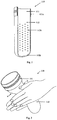
- Fig. 3 illustrates a schematic structural view of a bottle core of a soft core bottle under force according to an exemplary embodiment.
- the first bottle body 112 deforms due to the pressure.
- different parts of an inner side wall of the first bottle body 112 may contact with each other.
- clean water may be injected into the bottle core 110, and the first bottle body 112 may be kneaded in order to clean the bottle core 110.
- a plurality of protruding points 112a are provided on the inner side wall of the first bottle body 112 of the bottle core 110.
- friction generated on the inner side wall of the first bottle body 112 increases, which improves cleaning effect of kneading the bottle core 110 by manual work.
- the soft core bottle provided by the invention has the first bottle body of the bottle core made of soft material. Since the soft material may deform easily, a user may clean an inner wall of the bottle core by squeezing and kneading the bottle core, thus the problem that material of a commercially available bottle is always hard material causing inconvenience when the user cleans the bottle, is resolved. Therefore, an effect that the user may clean the bottle only by his/her hands conveniently and quickly without any tool is achieved.
- the plurality of protruding points are provided on the inner side wall of the first bottle body, thus the friction caused by rubbing the different parts of the inner side wall of the first bottle body with each other increases, which improves the cleaning effect of kneading the bottle core by manual work.
- the body portion and the bottom portion of the first bottle body may join with each other by the arcuate joint portion, such that the bottom portion of the first bottle body may forms a bottle bottom which can be cleaned in a range of 360°, i.e., any location on the bottom portion of the first bottle body can be cleaned.
- the difficulty of cleaning the bottle core by hands is lowered, and the cleaning effect is improved.
- Fig. 4 illustrates a schematic structural view of a soft core bottle according to an exemplary embodiment. As shown in Fig. 4 , the soft core bottle further includes the bottle housing 120.
- the bottle housing 120 is made of hard material.
- the bottle core 110 may be positioned in the bottle housing 120, and fixedly joined to the bottle housing 120 via the first bottle opening 111.
- the bottle housing 120 includes a second bottle opening 121 and a second bottle body 122.
- An inner side wall of the second bottle opening 121 is screwed to an outer side wall of the first bottle opening 111 by threads (e.g. screw threads).
- the first bottle opening 111 has an outer diameter which equals an inner diameter of the second bottle opening 121.
- the second bottle opening 121 may be fixed to the first bottle opening 111 in any one of the following two manners:
- the fixed manner of the second bottle opening 121 and the first bottle opening 111 may be another possible manner, which possible manner is also in the protection scope of the invention.
- the inner diameter of the first bottle opening 111 equals the inner diameter of the first bottle body 112
- the outer diameter of the first bottle opening 111 is larger than the outer diameter of the first bottle body 112
- the outer diameter of the first bottle body 112 is smaller than the inner diameter of the second bottle body 122, such that a gap is formed between the first bottle body 112 and the second bottle body 122, in order to make the soft core bottle adiabatic and heat retaining.
- the bottom portion of the first bottle body 112 contacts the bottom portion of the second bottle body 122 when the bottle core 110 is positioned in the bottle housing 120.
- the soft core bottle provided by the invention has the first bottle body of the bottle core made of soft material. Since the soft material may deform easily, a user may clean an inner wall of the bottle core by squeezing and kneading the bottle core, thus the problem that material of a commercially available bottle is always hard material causing inconvenience when the user cleans the bottle, is resolved. Therefore, an effect that the user may clean the bottle only by his/her hands conveniently and quickly without any tool is achieved.
- the inner side wall of the second bottle opening is screwed to the outer side wall of the first bottle opening by threads, such that the bottle core may be fixedly joined in the bottle housing, preventing the bottle core from swaying in or dropping from the bottle housing.
- the bottle core is prevented from swaying in the bottle housing after filled with liquid and the liquid is prevented from leaking out.
- the outer diameter of the first bottle body is smaller than the inner diameter of the second bottle body such that the gap is formed between the first bottle body and the second bottle body, a purpose that the soft core bottle is adiabatic and heat retaining is achieved.
- the soft core bottle may further include a bottle cover 130 as shown in Fig. 4 .
- the inner side wall of the second bottle opening 121 is screwed to a lower portion of the outer side wall of the first bottle opening 111 by threads 111c, and an inner side wall of an cover body 132 is screwed to an upper portion of the outer side wall of the first bottle opening 111 by threads 111b.
- the cover body 132 and the first bottle opening 111 may be fixed in following different manners:
- the fixed manner of the cover body 132 and the first bottle opening 111 may be another possible manner, which possible manner is also in the protection scope of the invention.
- Fig. 5 illustrates a schematic structural view of a soft core bottle according to an exemplary embodiment. As shown in Fig. 5 , the cover body 132 is joined at an upper edge of the second bottle opening 121 after screwed to the first bottle opening.
- the inner diameter of the cover body 132 equals the outer diameter of the first bottle opening 111
- the bottle cover 130 may be fixed to the first bottle opening 111 in such a manner that the inner side wall of the cover body 132 encloses the upper portion of the outer side wall of the first bottle opening 111 in an adsorption form, wherein the inner side wall of the cover body 132 and the upper portion of the outer side wall of the first bottle opening 111 may have threads or may not have threads.
- the inner diameter of the cover body 132 equals the outer diameter of the second bottle opening 121
- the bottle cover 130 may be fixed to the second bottle opening 121 in such a manner that the inner side wall of the cover body 132 encloses the upper portion of the outer side wall of the second bottle opening 121 in an adsorption form, wherein the inner side wall of the cover body 132 and the upper portion of the outer side wall of the second bottle opening 121 may have threads or may not have threads.
- the structure of the bottle cover 130 may also be another structure which may be used in connection with the first opening 111, such as the bottle cover 130 shown in Fig. 6 .
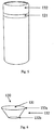
- Fig. 6 illustrates a schematic structural view of a bottle cover of a soft core bottle according to an exemplary embodiment.
- the bottle cover 130 includes a cover top 131 and the cover body 132, an outer diameter of a first end 132a of the cover body 132 is larger than an outer diameter of a second end 132b of the cover body 132, that is, the bottle cover 130 has a shape of circular truncated cone, cross sectional area of which decreases from top to bottom.
- the first end 132a of the cover body 132 connects with the cover top 131, and the outer diameter of the first end 132a of the cover body 132 is larger than the inner diameter of the first bottle opening, and the second end 132b of the cover body 132 is received by the first bottle opening.
- the hard material mentioned in various embodiments may be stainless steel, plastic, etc.
- the soft material may be silica gel, rubber, etc.
- the embodiments do not limit the hard material or the soft material to a specific type.
- the soft core bottle provided by the invention has the first bottle body of the bottle core made of soft material. Since the soft material may deform easily, a user may clean an inner wall of the bottle core by squeezing and kneading the bottle core, thus the problem that material of a commercially available bottle is always hard material causing inconvenience when the user cleans the bottle, is resolved. Therefore, an effect that the user may clean the bottle only by his/her hands conveniently and quickly without any tool is achieved.
- the inner side wall of the bottle cover is screwed to the upper portion of the outer side wall of the first bottle opening by threads, such that the bottle cover is fastened to the first bottle opening of the bottle core, ensuring the tightness of the bottle core, thus leakage of liquid in the bottle core can be prevented effectively after the bottle cover is screwed to the bottle core.
- the bottle cover is designed as a circular truncated cone shape whose cross sectional area decreases from top to bottom, the bottom end is received by the first bottle opening, thus the first bottle opening is plugged tightly.
- the bottle cover is designed as a circular cylinder shape, and parallel threads are provided on the outer side wall of the cover body of the bottle cover, the first bottle opening is plugged firmly, ensuring the tightness of the bottle core, thus leakage of liquid in the bottle core can be prevented effectively.
- the inner side wall of the cover body made of the soft material encloses the outer side wall of the first bottle opening or the outer side wall of the second bottle opening in an adsorptive manner, such that the first bottle opening can be plugged firmly by the bottle cover, ensuring the tightness of the bottle core, thus leakage of liquid in the bottle core can be prevented effectively.
Landscapes
- Engineering & Computer Science (AREA)
- Mechanical Engineering (AREA)
- Ceramic Engineering (AREA)
- Public Health (AREA)
- Animal Behavior & Ethology (AREA)
- General Health & Medical Sciences (AREA)
- Life Sciences & Earth Sciences (AREA)
- Veterinary Medicine (AREA)
- Health & Medical Sciences (AREA)
- Table Devices Or Equipment (AREA)
- Details Of Rigid Or Semi-Rigid Containers (AREA)
- Closures For Containers (AREA)
- Packages (AREA)
Abstract
Description
- The invention relates to a technical field of bottle, and more particularly, relates to a soft core bottle.
- Generally, a bottle is a container used for containing liquid. When the bottle is used for a long time, dirt may generate on an inner wall of the bottle.
- Recently, material of a commercially available bottle is always hard material. When a user needs to clean the inner wall of the bottle so as to remove dirt from the bottle, the user has to stretch his/her hand into the bottle and clean the bottle with a tool. Apparently, it is inconvenient to clean the bottle in this way.
- In order to solve a problem that material of a commercially available bottle is always hard material causing inconvenience when a user cleans the bottle, the invention provides a soft core bottle. Technical solutions of the invention are provided as follow:
- According to a first aspect of an embodiment of the invention, provided is a soft core bottle, which includes: a bottle housing and a bottle core;
- the bottle core comprises a first bottle opening and a first bottle body, and the first bottle body is made of soft material;
- the bottle housing is made of hard material; and
- the bottle core is fixedly joined in the bottle housing via the first bottle opening.
- The technical solution provided by the first aspect of the embodiments of the invention may have following beneficial effects: since the first bottle body of the bottle core is made of soft material which is easy to deform, when a user presses and kneads the bottle core, an inner side wall of the bottle core can be cleaned, thus solves a problem that material of a commercially available bottle is always hard material causing inconvenience when a user cleans the bottle, and an effect that the user may clean the bottle only by his/her hands conveniently and quickly without any tool is achieved.
- In a particular embodiment, the bottle housing comprises a second bottle opening and a second bottle body, and an inner side wall of the second bottle opening is screwed to an outer side wall of the first bottle opening by threads.
- This embodiment may have following beneficial effects: the inner side wall of the second bottle opening is screwed to the outer side wall of the first bottle opening by threads, such that the bottle core may be fixedly joined in the bottle housing, preventing the bottle core from swaying in or dropping out the bottle housing.
- In a particular embodiment, the soft core bottle further comprises a bottle cover;
the inner side wall of the second bottle opening is screwed to a lower portion of the outer side wall of the first bottle opening by threads; and
an inner side wall of the bottle cover is screwed to an upper portion of the outer side wall of the first bottle opening by threads. - This embodiment may have following beneficial effects: the inner side wall of the bottle cover is screwed to the upper portion of the outer side wall of the first bottle opening by threads, such that the bottle cover is fastened to the first bottle opening of the bottle core, ensuring the tightness of the bottle core, thus leakage of liquid in the bottle core can be prevented effectively after the bottle cover is screwed to the bottle core.
- In a particular embodiment, the soft core bottle further comprises a bottle cover, and the bottle cover is made of hard material;
the bottle cover comprises a cover top and a cover body, and an outer diameter of a first end of the cover body is larger than an outer diameter of a second end of the cover body, and the first end of the cover body is connected with the cover top,
wherein the outer diameter of the first end of the cover body is larger than an inner diameter of the first bottle opening, and the second end of the cover body is received by the first bottle opening;
or wherein an inner side wall of the first bottle opening is provided with at least two parallel threads, and an outer side wall of the cover body is fixed to an upper portion of the inner side wall of the first bottle opening by the parallel threads. - This embodiment may have following beneficial effects: since the bottle cover is designed as a circular cylinder shape whose cross sectional area decreases from top to bottom, or parallel threads are provided on the outer side wall of the cover body of the bottle cover, the first bottle opening is plugged firmly, ensuring the tightness of the bottle core, thus leakage of liquid in the bottle core can be prevented effectively.
- In a particular embodiment, the soft core bottle further comprises a bottle cover, and the bottle cover is made of soft material;
an inner diameter of an cover body equals an outer diameter of the first bottle opening, and an inner side wall of the cover body encloses the outer side wall of the first bottle opening in an adsorptive manner; or
the inner diameter of the cover body equals an outer diameter of the second bottle opening, and the inner side wall of the cover body encloses the outer side wall of the second bottle opening in the adsorptive manner. - This embodiment may have following beneficial effects: by means of the deformability and adsorptivity of soft material, the inner side wall of the cover body made of the soft material encloses the outer side wall of the first bottle opening or the outer side wall of the second bottle opening in the adsorption form, such that the first bottle opening can be plugged firmly by the bottle cover, ensuring the tightness of the bottle core, thus leakage of liquid in the bottle core can be prevented effectively.
- In a particular embodiment, a plurality of protruding points are provided on an inner side wall of the first bottle body.
- This embodiment may have following beneficial effects: since the plurality of protruding points are provided on the inner side wall of the first bottle body, when the bottle core is kneaded, friction on an inner side wall of the bottle core increases, which improves cleaning effect of kneading the bottle core by manual work.
- In a particular embodiment, the first bottle opening is joined with the first bottle body by soft material.
- In a particular embodiment, a bottle body portion and a bottom portion of the first bottle body are joined with each other via an arcuate joint portion.
- The This embodiment may have following beneficial effects: since the body portion and the bottom portion are joined with each other via the arcuate joint portion, the bottom portion of the first bottle body forms a bottle bottom which can be cleaned in a range of 360°, i.e., any location on the bottom portion of the first bottle body can be cleaned, lowering the difficulty of cleaning the bottle core by hands and improving the cleaning effect.
- In a particular embodiment, a bottom portion of the first bottle body contacts a bottom portion of the second bottle body when the bottle core is positioned in the second bottle body.
- This embodiment may have following beneficial effects:
- since the bottom portion of the first bottle body is located on and contacts the bottom portion of the second bottle body, the bottle core is prevented from swaying in the bottle housing after filled with liquid and the liquid is prevented from leaking out.
- In a particular embodiment, an inner diameter of the first bottle opening equals an inner diameter of the first bottle body, and an outer diameter of the first bottle opening is larger than an outer diameter of the first bottle body, and the outer diameter of the first bottle body is smaller than an inner diameter of the second bottle body.
- This embodiment may have following beneficial effects: since the outer diameter of the first bottle body is smaller than the inner diameter of the second bottle body, such that a gap is formed between the first bottle body and the second bottle body, a purpose that the soft core bottle is adiabatic and heat retaining is achieved.
- In a particular embodiment, the first bottle opening is firstly formed by injection molding with hard material, and the first bottle body is secondly formed by injection molding the first bottle opening with soft material such that part of the soft material encloses a surface of the first bottle opening.
- It should be appreciated that the general description in the above and the detailed description in the following are only illustrative, and do not limit the invention.
- The accompanying drawings, which are incorporated in and constitute a part of this specification, illustrate several aspects described below and together with the description, serve to explain the principles of the invention.
-
Fig. 1 illustrates a schematic structural view of a soft core bottle according to an exemplary embodiment; -
Fig. 2 illustrates a schematic structural view of a section of a bottle core of a soft core bottle according to an exemplary embodiment; -
Fig. 3 illustrates a schematic structural view of a bottle core of a soft core bottle under force according to an exemplary embodiment; -
Fig. 4 illustrates a schematic structural view of a soft core bottle according to an exemplary embodiment; -
Fig. 5 illustrates a schematic structural view of a soft core bottle according to an exemplary embodiment; -
Fig. 6 illustrates a schematic structural view of a bottle cover of a soft core bottle according to an exemplary embodiment. - Here, exemplary embodiments will be explained in detail, examples of the exemplary embodiments are illustrated in the drawings. When following description refers to the drawings, unless otherwise stated, similar numbers indicate similar elements throughout the drawings. Implementations described in the following exemplary embodiments do not represent all implementations consistent with the invention. In contrary, they are only examples of the apparatus and method which are in consistent with certain aspects of the invention as described in the appended claims in detail.
-
Fig. 1 illustrates a schematic structural view of a soft core bottle according to an exemplary embodiment. As shown inFig. 1 , the soft core bottle includes abottle housing 120 and a bottle core (or liner) 110. - The
bottle core 110 includes a first bottle opening 111 and afirst bottle body 112, and thefirst bottle body 112 is made of soft material. - The
bottle housing 120 is made of hard material, and thebottle core 110 is fixedly joined in thebottle housing 120 via the first bottle opening 111. - To sum up, the soft core bottle provided by the invention has the first bottle body of the bottle core made of soft material. Since the soft material may deform easily, a user may clean an inner wall of the bottle core by squeezing and kneading the bottle core, thus the problem that material of a commercially available bottle is always hard material causing inconvenience when the user cleans the bottle, is resolved. Therefore, an effect that the user may clean the bottle only by his/her hands conveniently and quickly without any tool is achieved.
- In order to allow the bottle core made of soft material matching with the bottle housing so as to achieve the effects of containing water and being cleaned easily, examples of the structure of the soft core bottle will be described below in combination with
Figs. 2 and4 . -
Fig. 2 illustrates a schematic structural view of a section of a bottle core of a soft core bottle according to an exemplary embodiment. As shown inFig. 2 , the soft core bottle includes abottle core 110. - The
bottle core 110 may include afirst bottle opening 111 and afirst bottle body 112, and thefirst bottle body 112 is made of soft material. The soft material may deform easily when it suffers pressure, and may recover when the pressure disappears. - Material of the first bottle opening 111 of the
bottle core 110 may be hard material or soft material. When the material of thefirst bottle opening 111 is hard material, thefirst bottle opening 111 may be joined with thefirst bottle body 112 by soft material. When the material of thefirst bottle opening 111 is soft material, thefirst bottle opening 111 and thefirst bottle body 112 may form an integral bottle core. - In an example, the
first bottle opening 111 is firstly formed by injection molding with hard material, and thefirst bottle body 112 is secondly formed by injection molding the first bottle opening 111 with soft material such that part of the soft material encloses a surface of thefirst bottle opening 111. Referring toFig. 2 , an inner layer 111a of the first bottle opening firstly formed by injection molding with hard material is shown as a black core portion of thefirst bottle opening 111, and the inner layer 111a of the first bottle opening is secondly formed by injection molding with soft material such that the soft material encloses a surface of the inner layer 111a of the first bottle opening, then thefirst bottle opening 111 is formed. - The
first bottle body 112 may include a body portion and abottom portion 112b which may join with each other via an arcuate joint portion, such that thebottom portion 112b of thefirst bottle body 112 forms a bottle bottom which can be cleaned in a range of 360°, i.e., any location on thebottom portion 112b of thefirst bottle body 112 can be cleaned. -
Fig. 3 illustrates a schematic structural view of a bottle core of a soft core bottle under force according to an exemplary embodiment. As shown inFig. 3 , when an outer side wall of thefirst bottle body 112 suffers a pressure from outside toward inside (for example, in pressure directions a and b), thefirst bottle body 112 deforms due to the pressure. When the deformation of thefirst bottle body 112 reaches to a certain extent, different parts of an inner side wall of thefirst bottle body 112 may contact with each other. At this moment, clean water may be injected into thebottle core 110, and thefirst bottle body 112 may be kneaded in order to clean thebottle core 110. - Further referring to
Fig. 2 , in an example, a plurality of protrudingpoints 112a are provided on the inner side wall of thefirst bottle body 112 of thebottle core 110. When thefirst bottle body 112 is kneaded, friction generated on the inner side wall of thefirst bottle body 112 increases, which improves cleaning effect of kneading thebottle core 110 by manual work. - To sum up, the soft core bottle provided by the invention has the first bottle body of the bottle core made of soft material. Since the soft material may deform easily, a user may clean an inner wall of the bottle core by squeezing and kneading the bottle core, thus the problem that material of a commercially available bottle is always hard material causing inconvenience when the user cleans the bottle, is resolved. Therefore, an effect that the user may clean the bottle only by his/her hands conveniently and quickly without any tool is achieved.
- In the present embodiment, the plurality of protruding points are provided on the inner side wall of the first bottle body, thus the friction caused by rubbing the different parts of the inner side wall of the first bottle body with each other increases, which improves the cleaning effect of kneading the bottle core by manual work.
- In the present embodiment, the body portion and the bottom portion of the first bottle body may join with each other by the arcuate joint portion, such that the bottom portion of the first bottle body may forms a bottle bottom which can be cleaned in a range of 360°, i.e., any location on the bottom portion of the first bottle body can be cleaned. Thereby, the difficulty of cleaning the bottle core by hands is lowered, and the cleaning effect is improved.
-
Fig. 4 illustrates a schematic structural view of a soft core bottle according to an exemplary embodiment. As shown inFig. 4 , the soft core bottle further includes thebottle housing 120. - The
bottle housing 120 is made of hard material. Thebottle core 110 may be positioned in thebottle housing 120, and fixedly joined to thebottle housing 120 via thefirst bottle opening 111. Thebottle housing 120 includes a second bottle opening 121 and asecond bottle body 122. An inner side wall of the second bottle opening 121 is screwed to an outer side wall of thefirst bottle opening 111 by threads (e.g. screw threads). Thefirst bottle opening 111 has an outer diameter which equals an inner diameter of thesecond bottle opening 121. - It should be noted that the second bottle opening 121 may be fixed to the first bottle opening 111 in any one of the following two manners:
- In a first manner, the threads on the inner side wall of the second bottle opening 121 and the outer side wall of the
first bottle opening 111 are rotation type threads, the inner side wall of the second bottle opening 121 is screwed to the outer side wall of thefirst bottle opening 111 by the threads in a rotation manner. The threads on both the inner side wall of the second bottle opening 121 and the outer side wall of thefirst bottle opening 111 are male (or external) threads; or the threads on the inner side wall of the second bottle opening 121 are male threads while the threads on the outer side wall of thefirst bottle opening 111 are female (or internal) threads; or the threads on the inner side wall of the second bottle opening 121 are female threads while the threads on the outer side wall of thefirst bottle opening 111 are male threads. - In a second manner, the threads on the inner side wall of the second bottle opening 121 and the outer side wall of the
first bottle opening 111 are non-rotation type threads, and the threads are made of soft material. The threads on both the inner side wall of the second bottle opening 121 and the outer side wall of thefirst bottle opening 111 are parallel with thefirst bottle opening 111. The inner side wall of the second bottle opening 121 is fixed to the outer side wall of thefirst bottle opening 111 by the threads in a stuck manner. The threads on both the inner side wall of the second bottle opening 121 and the outer side wall of thefirst bottle opening 111 are male threads; or the threads on the inner side wall of the second bottle opening 121 are male threads while the threads on the outer side wall of thefirst bottle opening 111 are female threads. It should be noted that the numbers of the threads on the second bottle opening 121 and/or thefirst bottle opening 111 are at least two in the case that the threads on both the inner side wall of the second bottle opening 121 and the outer side wall of thefirst bottle opening 111 are male threads, in order to fasten thebottle core 110. - For example, the fixed manner of the second bottle opening 121 and the
first bottle opening 111 may be another possible manner, which possible manner is also in the protection scope of the invention. - In an example, when the
bottle core 110 is provided in thebottle housing 120, the inner diameter of the first bottle opening 111 equals the inner diameter of thefirst bottle body 112, and the outer diameter of thefirst bottle opening 111 is larger than the outer diameter of thefirst bottle body 112, and the outer diameter of thefirst bottle body 112 is smaller than the inner diameter of thesecond bottle body 122, such that a gap is formed between thefirst bottle body 112 and thesecond bottle body 122, in order to make the soft core bottle adiabatic and heat retaining. - In an example, in order to prevent the
bottle core 110 from swaying in thebottle housing 120 after filled with liquid, the bottom portion of thefirst bottle body 112 contacts the bottom portion of thesecond bottle body 122 when thebottle core 110 is positioned in thebottle housing 120. - To sum up, the soft core bottle provided by the invention has the first bottle body of the bottle core made of soft material. Since the soft material may deform easily, a user may clean an inner wall of the bottle core by squeezing and kneading the bottle core, thus the problem that material of a commercially available bottle is always hard material causing inconvenience when the user cleans the bottle, is resolved. Therefore, an effect that the user may clean the bottle only by his/her hands conveniently and quickly without any tool is achieved.
- In the present embodiment, the inner side wall of the second bottle opening is screwed to the outer side wall of the first bottle opening by threads, such that the bottle core may be fixedly joined in the bottle housing, preventing the bottle core from swaying in or dropping from the bottle housing.
- In the present embodiment, by making the bottom portion of the first bottle body be located on and contact the bottom portion of the second bottle body, the bottle core is prevented from swaying in the bottle housing after filled with liquid and the liquid is prevented from leaking out.
- In the present embodiment, since the outer diameter of the first bottle body is smaller than the inner diameter of the second bottle body such that the gap is formed between the first bottle body and the second bottle body, a purpose that the soft core bottle is adiabatic and heat retaining is achieved.
- In other embodiments, in order to keep water temperature in the bottle core of the soft core bottle, or carry the soft core bottle (the bottle core of which is filled with water) conveniently, the soft core bottle may further include a
bottle cover 130 as shown inFig. 4 . - Further referring to
Fig. 4 , the inner side wall of the second bottle opening 121 is screwed to a lower portion of the outer side wall of thefirst bottle opening 111 bythreads 111c, and an inner side wall of ancover body 132 is screwed to an upper portion of the outer side wall of thefirst bottle opening 111 bythreads 111b. - In the case that the
bottle cover 130 is made of hard material, if the threads are made of materials with different properties, thecover body 132 and thefirst bottle opening 111 may be fixed in following different manners: - (1) In the case that the
bottle cover 130 is made of hard material and the inner diameter of thecover body 132 equals the outer diameter of thefirst bottle opening 111, thecover body 132 may be fixed with the first bottle opening 111 in any one of the following two manners:- In a first manner, the threads on the inner side wall of the
cover body 132 and the outer side wall of thefirst bottle opening 111 are rotation type threads, the inner side wall of thecover body 132 is screwed to the outer side wall of thefirst bottle opening 111 by the threads in a rotation manner. The threads on both the inner side wall of thecover body 132 and the outer side wall of thefirst bottle opening 111 are male threads; or the threads on the inner side wall of thecover body 132 are male threads while the threads on the outer side wall of thefirst bottle opening 111 are female threads; or the threads on the inner side wall of thecover body 132 are female threads while the threads on the outer side wall of thefirst bottle opening 111 are male threads. - In a second manner, the threads on the inner side wall of the
cover body 132 and the outer side wall of thefirst bottle opening 111 are non-rotation type threads, and the threads are made of soft material. The threads on both the inner side wall of thecover body 132 and the outer side wall of thefirst bottle opening 111 are parallel with thefirst bottle opening 111. The inner side wall of thecover body 132 is fixed to the outer side wall of thefirst bottle opening 111 by the threads in a stuck manner. The threads on both the inner side wall of thecover body 132 and the outer side wall of thefirst bottle opening 111 are male threads; or the threads on the inner side wall of thecover body 132 are male threads while the threads on the outer side wall of thefirst bottle opening 111 are female threads. It should be noted that the numbers of the threads on thecover body 132 and/or thefirst bottle opening 111 are at least two in the case that the threads on both the inner side wall of thecover body 132 and the outer side wall of thefirst bottle opening 111 are male threads, in order to fasten thebottle cover 130.
cover body 132 and thefirst bottle opening 111 may be another possible manner, which possible manner is also in the protection scope of the invention. - In a first manner, the threads on the inner side wall of the
- (2) In the case that the
bottle cover 130 is made of hard material and the outer diameter of thecover body 132 equals the inner diameter of thefirst bottle opening 111, thecover body 132 may be fixed with the first bottle opening 111 in any one of the following two manners:- In a first manner, the threads on the outer side wall of the
cover body 132 and thethreads 111b on the inner side wall of thefirst bottle opening 111 are rotation type threads, the outer side wall of thecover body 132 is screwed to the inner side wall of thefirst bottle opening 111 by the threads in a rotation manner. The threads on the outer side wall of thecover body 132 and thethreads 111b on the inner side wall of thefirst bottle opening 111 are male threads; or the threads on the outer side wall of thecover body 132 are male threads while thethreads 111b on the inner side wall of thefirst bottle opening 111 are female threads; or the threads on the outer side wall of thecover body 132 are female threads while thethreads 111b on the inner side wall of thefirst bottle opening 111 are male threads. - In a second manner, the threads on the outer side wall of the
cover body 132 andthreads 111b on the inner side wall of thefirst bottle opening 111 are non-rotation type threads, and the threads are made of soft material. The threads on the outer side wall of thecover body 132 and thethreads 111b on the inner side wall of thefirst bottle opening 111 are parallel with thefirst bottle opening 111. The outer side wall of thecover body 132 is fixed to the inner side wall of thefirst bottle opening 111 by the threads in a stuck manner. The threads on the outer side wall of thecover body 132 and thethreads 111b on the inner side wall of thefirst bottle opening 111 are male threads; or the threads on the outer side wall of thecover body 132 are male threads while thethreads 111b on the inner side wall of thefirst bottle opening 111 are female threads. It should be noted that the numbers of the threads on thecover body 132 and/or thefirst bottle opening 111 are at least two in the case that the threads on the outer side wall of thecover body 132 and thethreads 111b on the inner side wall of thefirst bottle opening 111 are male threads, in order to fasten thebottle cover 130.
- In a first manner, the threads on the outer side wall of the
- For example, the fixed manner of the
cover body 132 and thefirst bottle opening 111 may be another possible manner, which possible manner is also in the protection scope of the invention. -
Fig. 5 illustrates a schematic structural view of a soft core bottle according to an exemplary embodiment. As shown inFig. 5 , thecover body 132 is joined at an upper edge of the second bottle opening 121 after screwed to the first bottle opening. - Further referring to
Fig. 4 , in the case that thebottle cover 130 is made of soft material, the inner diameter of thecover body 132 equals the outer diameter of thefirst bottle opening 111, and thebottle cover 130 may be fixed to the first bottle opening 111 in such a manner that the inner side wall of thecover body 132 encloses the upper portion of the outer side wall of the first bottle opening 111 in an adsorption form, wherein the inner side wall of thecover body 132 and the upper portion of the outer side wall of thefirst bottle opening 111 may have threads or may not have threads. - In an example, in the case that the
bottle cover 130 is made of soft material, the inner diameter of thecover body 132 equals the outer diameter of the second bottle opening 121, and thebottle cover 130 may be fixed to the second bottle opening 121 in such a manner that the inner side wall of thecover body 132 encloses the upper portion of the outer side wall of the second bottle opening 121 in an adsorption form, wherein the inner side wall of thecover body 132 and the upper portion of the outer side wall of the second bottle opening 121 may have threads or may not have threads. - In a possible manner, the structure of the
bottle cover 130 may also be another structure which may be used in connection with thefirst opening 111, such as thebottle cover 130 shown inFig. 6 . -
Fig. 6 illustrates a schematic structural view of a bottle cover of a soft core bottle according to an exemplary embodiment. As shown inFig. 6 , thebottle cover 130 includes acover top 131 and thecover body 132, an outer diameter of afirst end 132a of thecover body 132 is larger than an outer diameter of asecond end 132b of thecover body 132, that is, thebottle cover 130 has a shape of circular truncated cone, cross sectional area of which decreases from top to bottom. Thefirst end 132a of thecover body 132 connects with thecover top 131, and the outer diameter of thefirst end 132a of thecover body 132 is larger than the inner diameter of the first bottle opening, and thesecond end 132b of thecover body 132 is received by the first bottle opening. - It should be noted that the hard material mentioned in various embodiments may be stainless steel, plastic, etc., and the soft material may be silica gel, rubber, etc. The embodiments do not limit the hard material or the soft material to a specific type.
- To sum up, the soft core bottle provided by the invention has the first bottle body of the bottle core made of soft material. Since the soft material may deform easily, a user may clean an inner wall of the bottle core by squeezing and kneading the bottle core, thus the problem that material of a commercially available bottle is always hard material causing inconvenience when the user cleans the bottle, is resolved. Therefore, an effect that the user may clean the bottle only by his/her hands conveniently and quickly without any tool is achieved.
- In a particular embodiment, the inner side wall of the bottle cover is screwed to the upper portion of the outer side wall of the first bottle opening by threads, such that the bottle cover is fastened to the first bottle opening of the bottle core, ensuring the tightness of the bottle core, thus leakage of liquid in the bottle core can be prevented effectively after the bottle cover is screwed to the bottle core.
- In a particular embodiment, since the bottle cover is designed as a circular truncated cone shape whose cross sectional area decreases from top to bottom, the bottom end is received by the first bottle opening, thus the first bottle opening is plugged tightly.
- In a particular embodiment, the bottle cover is designed as a circular cylinder shape, and parallel threads are provided on the outer side wall of the cover body of the bottle cover, the first bottle opening is plugged firmly, ensuring the tightness of the bottle core, thus leakage of liquid in the bottle core can be prevented effectively.
- In a particular embodiment, by means of the deformability and adsorptivity of soft material, the inner side wall of the cover body made of the soft material encloses the outer side wall of the first bottle opening or the outer side wall of the second bottle opening in an adsorptive manner, such that the first bottle opening can be plugged firmly by the bottle cover, ensuring the tightness of the bottle core, thus leakage of liquid in the bottle core can be prevented effectively.
Claims (11)
- A soft core bottle, characterized in that the soft core bottle comprises: a bottle housing (120) and a bottle core (110);
the bottle core (110) comprises a first bottle opening (111) and a first bottle body (112), and the first bottle body (112) is made of soft material;
the bottle housing (120) is made of hard material; and
the bottle core (110) is fixedly joined in the bottle housing (120) via the first bottle opening (111). - The soft core bottle according to claim 1, characterized in that the bottle housing (120) comprises a second bottle opening (121) and a second bottle body (122), and an inner side wall of the second bottle opening (121) is screwed to an outer side wall of the first bottle opening (111) by threads.
- The soft core bottle according to claim 1 or 2, characterized in that the soft core bottle further comprises a bottle cover (130);
the inner side wall of the second bottle opening (121) is screwed to a lower portion of the outer side wall of the first bottle opening (111) by threads; and
an inner side wall of the bottle cover (130) is screwed to an upper portion of the outer side wall of the first bottle opening (111) by threads. - The soft core bottle according to claim 1 or 2, characterized in that the soft core bottle further comprises a bottle cover (130), and the bottle (130) cover is made of hard material;
the bottle cover (130) comprises a cover top (131) and a cover body (132), and an outer diameter of a first end (131a) of the cover body (132) is larger than an outer diameter of a second end (131b) of the cover body (132), and the first end (131a) of the cover body (132) is connected with the cover top (131),
wherein the outer diameter of the first end (131a) of the cover body (132) is larger than an inner diameter of the first bottle opening (111), and the second end (131b) of the cover body (132) is received by the first bottle opening (111); or
wherein an inner side wall of the first bottle opening (111) is provided with at least two parallel threads, and an outer side wall of the cover body (132) is fixed to an upper portion of the inner side wall of the first bottle opening (111) by the parallel threads. - The soft core bottle according to claim 1 or 2, characterized in that the soft core bottle further comprises a bottle cover (130), and the bottle cover (130) is made of soft material;
an inner diameter of an cover body (132) of the bottle cover (130) equals an outer diameter of the first bottle opening (111), and an inner side wall of the cover body (132) encloses the outer side wall of the first bottle opening (111) in an adsorptive manner; or
the inner diameter of the cover body (132) equals an outer diameter of the second bottle opening (121), and the inner side wall of the cover body (132) encloses the outer side wall of the second bottle opening (121) in an adsorptive manner. - The soft core bottle according to any of claims 1-5, characterized in that a plurality of protruding points (112a) are provided on an inner side wall of the first bottle body (112).
- The soft core bottle according to any of claims 1-6, characterized in that the first bottle opening (111) is joined with the first bottle body (112) by soft material.
- The soft core bottle according to any of claim 1-7, characterized in that a bottle body portion and a bottom portion (112b) of the first bottle body (112) are joined with each other via an arcuate joint portion.
- The soft core bottle according to any of claims 2-8, characterized in that a bottom portion (112b) of the first bottle body (112) contacts a bottom portion of the second bottle body (122) when the bottle core (110) is positioned in the second bottle body (122).
- The soft core bottle according to any of claims 2-9, characterized in that an inner diameter of the first bottle opening (111) equals an inner diameter of the first bottle body (112), and an outer diameter of the first bottle opening (111) is larger than an outer diameter of the first bottle body (112), and the outer diameter of the first bottle body (112) is smaller than an inner diameter of the second bottle body (122).
- The soft core bottle according to any of claims 1-10, characterized in that the first bottle opening (111) is firstly formed by injection molding with hard material, and the first bottle body (112) is secondly formed by injection molding the first bottle opening (111) with soft material such that part of the soft material encloses a surface of the first bottle opening (111).
Applications Claiming Priority (1)
| Application Number | Priority Date | Filing Date | Title |
|---|---|---|---|
| CN201610150867.4A CN105708272B (en) | 2016-03-16 | 2016-03-16 | soft core cup |
Publications (2)
| Publication Number | Publication Date |
|---|---|
| EP3228213A1 true EP3228213A1 (en) | 2017-10-11 |
| EP3228213B1 EP3228213B1 (en) | 2019-01-02 |
Family
ID=56158737
Family Applications (1)
| Application Number | Title | Priority Date | Filing Date |
|---|---|---|---|
| EP17160564.5A Not-in-force EP3228213B1 (en) | 2016-03-16 | 2017-03-13 | Soft core bottle |
Country Status (7)
| Country | Link |
|---|---|
| US (1) | US10710772B2 (en) |
| EP (1) | EP3228213B1 (en) |
| JP (1) | JP6427206B2 (en) |
| KR (1) | KR20180033248A (en) |
| CN (1) | CN105708272B (en) |
| RU (1) | RU2664821C2 (en) |
| WO (1) | WO2017156988A1 (en) |
Families Citing this family (3)
| Publication number | Priority date | Publication date | Assignee | Title |
|---|---|---|---|---|
| CN105708272B (en) | 2016-03-16 | 2018-11-30 | 北京小米移动软件有限公司 | soft core cup |
| CN216425428U (en) * | 2020-11-10 | 2022-05-03 | 卡迈力有限公司 | Deformable sleeve with elastic core structure |
| CN112438205B (en) * | 2020-12-21 | 2021-11-16 | 罗源县凤山镇企业服务中心 | Light-shading tissue culture bottle |
Citations (5)
| Publication number | Priority date | Publication date | Assignee | Title |
|---|---|---|---|---|
| JPS51157379U (en) * | 1975-06-06 | 1976-12-15 | ||
| US5882119A (en) * | 1997-02-24 | 1999-03-16 | Fadal, Ii; Robert E. | Portable liquid containers |
| US20050056610A1 (en) * | 2003-09-16 | 2005-03-17 | Playtex Products, Inc. | Bottle assembly |
| US20130075393A1 (en) * | 2011-08-16 | 2013-03-28 | David B. Haynie | Collapsible bottle |
| CN203609143U (en) * | 2013-12-05 | 2014-05-28 | 陕西理工学院 | Portable water cup |
Family Cites Families (19)
| Publication number | Priority date | Publication date | Assignee | Title |
|---|---|---|---|---|
| US2876113A (en) * | 1956-08-13 | 1959-03-03 | Donn C Barton | Packaging device for merchandising food concentrates |
| US3784039A (en) * | 1972-01-10 | 1974-01-08 | Illinois Tool Works | Nursing bottle construction and assembly |
| CA1297807C (en) * | 1987-07-08 | 1992-03-24 | Frank R. Mckeown | Pressure applicator |
| US4821896A (en) * | 1988-03-24 | 1989-04-18 | Cheng Ping N | Nursing bottle with a liner and vent |
| US5195658A (en) * | 1991-03-12 | 1993-03-23 | Toyo Bussan Kabushiki Kaisha | Disposable container |
| US5356016A (en) * | 1991-11-20 | 1994-10-18 | Wiedemann Warren T | Baby nursing bottle |
| US20020153381A1 (en) * | 2001-04-24 | 2002-10-24 | Jeff Rohe | Ergonomic handles and grips for beverage containers |
| US20050184075A1 (en) * | 2004-02-24 | 2005-08-25 | Niko Designs, Llc | One-piece soft spout valve assembly for a no-spill drinking cup |
| CN2790256Y (en) * | 2005-04-26 | 2006-06-28 | 钟建雄 | a drinking water bag |
| CN2800889Y (en) * | 2005-07-13 | 2006-08-02 | 王凯 | Portable and clean type folding cup |
| CN201542254U (en) * | 2009-08-17 | 2010-08-11 | 廖令谦 | Double-layer cup with soft rubber casing |
| JP5713235B2 (en) | 2011-03-31 | 2015-05-07 | 株式会社吉野工業所 | Storage case for contact lenses |
| CN202154451U (en) * | 2011-08-11 | 2012-03-07 | 上海海事大学 | Water cup with easy cleaning |
| JP5661580B2 (en) * | 2011-08-29 | 2015-01-28 | 株式会社吉野工業所 | Double container |
| CN203914344U (en) * | 2013-12-17 | 2014-11-05 | 浙江朝日硅科技有限公司 | A kind of port organization of soft water tumbler |
| CN203914352U (en) * | 2014-05-04 | 2014-11-05 | 程锋 | transparent page double-layer cup |
| CN204232782U (en) * | 2014-11-24 | 2015-04-01 | 中州大学 | Split type water cup |
| CN105105501A (en) * | 2015-09-21 | 2015-12-02 | 宋正岩 | Foldable water cup |
| CN105708272B (en) * | 2016-03-16 | 2018-11-30 | 北京小米移动软件有限公司 | soft core cup |
-
2016
- 2016-03-16 CN CN201610150867.4A patent/CN105708272B/en not_active Expired - Fee Related
- 2016-09-06 RU RU2017103921A patent/RU2664821C2/en active
- 2016-09-06 KR KR1020187005142A patent/KR20180033248A/en not_active Ceased
- 2016-09-06 WO PCT/CN2016/098181 patent/WO2017156988A1/en not_active Ceased
- 2016-09-06 JP JP2016566639A patent/JP6427206B2/en active Active
-
2017
- 2017-02-17 US US15/435,698 patent/US10710772B2/en active Active
- 2017-03-13 EP EP17160564.5A patent/EP3228213B1/en not_active Not-in-force
Patent Citations (5)
| Publication number | Priority date | Publication date | Assignee | Title |
|---|---|---|---|---|
| JPS51157379U (en) * | 1975-06-06 | 1976-12-15 | ||
| US5882119A (en) * | 1997-02-24 | 1999-03-16 | Fadal, Ii; Robert E. | Portable liquid containers |
| US20050056610A1 (en) * | 2003-09-16 | 2005-03-17 | Playtex Products, Inc. | Bottle assembly |
| US20130075393A1 (en) * | 2011-08-16 | 2013-03-28 | David B. Haynie | Collapsible bottle |
| CN203609143U (en) * | 2013-12-05 | 2014-05-28 | 陕西理工学院 | Portable water cup |
Also Published As
| Publication number | Publication date |
|---|---|
| US10710772B2 (en) | 2020-07-14 |
| KR20180033248A (en) | 2018-04-02 |
| WO2017156988A1 (en) | 2017-09-21 |
| JP6427206B2 (en) | 2018-11-21 |
| RU2664821C2 (en) | 2018-08-22 |
| US20170267404A1 (en) | 2017-09-21 |
| JP2018516095A (en) | 2018-06-21 |
| CN105708272B (en) | 2018-11-30 |
| CN105708272A (en) | 2016-06-29 |
| EP3228213B1 (en) | 2019-01-02 |
Similar Documents
| Publication | Publication Date | Title |
|---|---|---|
| KR101479069B1 (en) | A Safety Cap | |
| EP3228213A1 (en) | Soft core bottle | |
| KR20140126245A (en) | Beverage container | |
| JP4943269B2 (en) | Sample extraction container | |
| CN104909056B (en) | Straw cover capable of being automatically sealed | |
| US7891027B2 (en) | Drain vent seal | |
| CN104909040A (en) | No-spout lid that opens and closes automatically | |
| KR101161317B1 (en) | Vessel having double packing for double cap | |
| TW202321124A (en) | Lid assembly and container with lid | |
| CN203740311U (en) | Bottle cap buckling structure | |
| CN209733328U (en) | Cup convenient to open | |
| CN204995126U (en) | Novel pressure release exhaust part and contain thermos cup of this part | |
| CN106419643B (en) | Sanitary stirring kettle | |
| CN205795435U (en) | Soft core water tumbler | |
| CN108262299B (en) | Waste liquid bottle and liquid suction device for plate washer | |
| KR101169553B1 (en) | Vessel having double packing for double cap | |
| CN204636045U (en) | A kind of adjustable for height pot cover | |
| TWI812503B (en) | Lid assembly and container with lid | |
| CN216822852U (en) | Switch tea stewing net | |
| CN219515563U (en) | Dropper container and cosmetic | |
| CN209536429U (en) | A pressure balance device and a suction cup using the same | |
| CN216064622U (en) | Air dedusting agent storage device capable of reversely spraying | |
| CN213503788U (en) | Anti-drop water guide core, water taking device and water taking system | |
| CN214691131U (en) | a liquid storage bottle | |
| CN209966184U (en) | Cup body assembly and food processor with same |
Legal Events
| Date | Code | Title | Description |
|---|---|---|---|
| PUAI | Public reference made under article 153(3) epc to a published international application that has entered the european phase |
Free format text: ORIGINAL CODE: 0009012 |
|
| STAA | Information on the status of an ep patent application or granted ep patent |
Free format text: STATUS: THE APPLICATION HAS BEEN PUBLISHED |
|
| AK | Designated contracting states |
Kind code of ref document: A1 Designated state(s): AL AT BE BG CH CY CZ DE DK EE ES FI FR GB GR HR HU IE IS IT LI LT LU LV MC MK MT NL NO PL PT RO RS SE SI SK SM TR |
|
| AX | Request for extension of the european patent |
Extension state: BA ME |
|
| STAA | Information on the status of an ep patent application or granted ep patent |
Free format text: STATUS: REQUEST FOR EXAMINATION WAS MADE |
|
| 17P | Request for examination filed |
Effective date: 20180409 |
|
| RBV | Designated contracting states (corrected) |
Designated state(s): AL AT BE BG CH CY CZ DE DK EE ES FI FR GB GR HR HU IE IS IT LI LT LU LV MC MK MT NL NO PL PT RO RS SE SI SK SM TR |
|
| GRAP | Despatch of communication of intention to grant a patent |
Free format text: ORIGINAL CODE: EPIDOSNIGR1 |
|
| RIC1 | Information provided on ipc code assigned before grant |
Ipc: A45F 3/16 20060101AFI20180723BHEP Ipc: A45F 3/20 20060101ALN20180723BHEP Ipc: A45F 3/18 20060101ALN20180723BHEP |
|
| STAA | Information on the status of an ep patent application or granted ep patent |
Free format text: STATUS: GRANT OF PATENT IS INTENDED |
|
| INTG | Intention to grant announced |
Effective date: 20180830 |
|
| GRAS | Grant fee paid |
Free format text: ORIGINAL CODE: EPIDOSNIGR3 |
|
| GRAA | (expected) grant |
Free format text: ORIGINAL CODE: 0009210 |
|
| STAA | Information on the status of an ep patent application or granted ep patent |
Free format text: STATUS: THE PATENT HAS BEEN GRANTED |
|
| AK | Designated contracting states |
Kind code of ref document: B1 Designated state(s): AL AT BE BG CH CY CZ DE DK EE ES FI FR GB GR HR HU IE IS IT LI LT LU LV MC MK MT NL NO PL PT RO RS SE SI SK SM TR |
|
| REG | Reference to a national code |
Ref country code: GB Ref legal event code: FG4D |
|
| RIN1 | Information on inventor provided before grant (corrected) |
Inventor name: ZHANG, LEI Inventor name: LI, NINGNING Inventor name: XING, ZHENG |
|
| REG | Reference to a national code |
Ref country code: CH Ref legal event code: EP Ref country code: AT Ref legal event code: REF Ref document number: 1083322 Country of ref document: AT Kind code of ref document: T Effective date: 20190115 |
|
| REG | Reference to a national code |
Ref country code: IE Ref legal event code: FG4D |
|
| REG | Reference to a national code |
Ref country code: DE Ref legal event code: R096 Ref document number: 602017001614 Country of ref document: DE |
|
| REG | Reference to a national code |
Ref country code: NL Ref legal event code: MP Effective date: 20190102 |
|
| REG | Reference to a national code |
Ref country code: LT Ref legal event code: MG4D |
|
| REG | Reference to a national code |
Ref country code: AT Ref legal event code: MK05 Ref document number: 1083322 Country of ref document: AT Kind code of ref document: T Effective date: 20190102 |
|
| PG25 | Lapsed in a contracting state [announced via postgrant information from national office to epo] |
Ref country code: NL Free format text: LAPSE BECAUSE OF FAILURE TO SUBMIT A TRANSLATION OF THE DESCRIPTION OR TO PAY THE FEE WITHIN THE PRESCRIBED TIME-LIMIT Effective date: 20190102 |
|
| PG25 | Lapsed in a contracting state [announced via postgrant information from national office to epo] |
Ref country code: SE Free format text: LAPSE BECAUSE OF FAILURE TO SUBMIT A TRANSLATION OF THE DESCRIPTION OR TO PAY THE FEE WITHIN THE PRESCRIBED TIME-LIMIT Effective date: 20190102 Ref country code: PT Free format text: LAPSE BECAUSE OF FAILURE TO SUBMIT A TRANSLATION OF THE DESCRIPTION OR TO PAY THE FEE WITHIN THE PRESCRIBED TIME-LIMIT Effective date: 20190502 Ref country code: ES Free format text: LAPSE BECAUSE OF FAILURE TO SUBMIT A TRANSLATION OF THE DESCRIPTION OR TO PAY THE FEE WITHIN THE PRESCRIBED TIME-LIMIT Effective date: 20190102 Ref country code: LT Free format text: LAPSE BECAUSE OF FAILURE TO SUBMIT A TRANSLATION OF THE DESCRIPTION OR TO PAY THE FEE WITHIN THE PRESCRIBED TIME-LIMIT Effective date: 20190102 Ref country code: PL Free format text: LAPSE BECAUSE OF FAILURE TO SUBMIT A TRANSLATION OF THE DESCRIPTION OR TO PAY THE FEE WITHIN THE PRESCRIBED TIME-LIMIT Effective date: 20190102 Ref country code: NO Free format text: LAPSE BECAUSE OF FAILURE TO SUBMIT A TRANSLATION OF THE DESCRIPTION OR TO PAY THE FEE WITHIN THE PRESCRIBED TIME-LIMIT Effective date: 20190402 Ref country code: FI Free format text: LAPSE BECAUSE OF FAILURE TO SUBMIT A TRANSLATION OF THE DESCRIPTION OR TO PAY THE FEE WITHIN THE PRESCRIBED TIME-LIMIT Effective date: 20190102 |
|
| PG25 | Lapsed in a contracting state [announced via postgrant information from national office to epo] |
Ref country code: IS Free format text: LAPSE BECAUSE OF FAILURE TO SUBMIT A TRANSLATION OF THE DESCRIPTION OR TO PAY THE FEE WITHIN THE PRESCRIBED TIME-LIMIT Effective date: 20190502 Ref country code: BG Free format text: LAPSE BECAUSE OF FAILURE TO SUBMIT A TRANSLATION OF THE DESCRIPTION OR TO PAY THE FEE WITHIN THE PRESCRIBED TIME-LIMIT Effective date: 20190402 Ref country code: RS Free format text: LAPSE BECAUSE OF FAILURE TO SUBMIT A TRANSLATION OF THE DESCRIPTION OR TO PAY THE FEE WITHIN THE PRESCRIBED TIME-LIMIT Effective date: 20190102 Ref country code: HR Free format text: LAPSE BECAUSE OF FAILURE TO SUBMIT A TRANSLATION OF THE DESCRIPTION OR TO PAY THE FEE WITHIN THE PRESCRIBED TIME-LIMIT Effective date: 20190102 Ref country code: LV Free format text: LAPSE BECAUSE OF FAILURE TO SUBMIT A TRANSLATION OF THE DESCRIPTION OR TO PAY THE FEE WITHIN THE PRESCRIBED TIME-LIMIT Effective date: 20190102 Ref country code: GR Free format text: LAPSE BECAUSE OF FAILURE TO SUBMIT A TRANSLATION OF THE DESCRIPTION OR TO PAY THE FEE WITHIN THE PRESCRIBED TIME-LIMIT Effective date: 20190403 |
|
| REG | Reference to a national code |
Ref country code: DE Ref legal event code: R097 Ref document number: 602017001614 Country of ref document: DE |
|
| PG25 | Lapsed in a contracting state [announced via postgrant information from national office to epo] |
Ref country code: MC Free format text: LAPSE BECAUSE OF FAILURE TO SUBMIT A TRANSLATION OF THE DESCRIPTION OR TO PAY THE FEE WITHIN THE PRESCRIBED TIME-LIMIT Effective date: 20190102 Ref country code: AL Free format text: LAPSE BECAUSE OF FAILURE TO SUBMIT A TRANSLATION OF THE DESCRIPTION OR TO PAY THE FEE WITHIN THE PRESCRIBED TIME-LIMIT Effective date: 20190102 Ref country code: SK Free format text: LAPSE BECAUSE OF FAILURE TO SUBMIT A TRANSLATION OF THE DESCRIPTION OR TO PAY THE FEE WITHIN THE PRESCRIBED TIME-LIMIT Effective date: 20190102 Ref country code: EE Free format text: LAPSE BECAUSE OF FAILURE TO SUBMIT A TRANSLATION OF THE DESCRIPTION OR TO PAY THE FEE WITHIN THE PRESCRIBED TIME-LIMIT Effective date: 20190102 Ref country code: DK Free format text: LAPSE BECAUSE OF FAILURE TO SUBMIT A TRANSLATION OF THE DESCRIPTION OR TO PAY THE FEE WITHIN THE PRESCRIBED TIME-LIMIT Effective date: 20190102 Ref country code: IT Free format text: LAPSE BECAUSE OF FAILURE TO SUBMIT A TRANSLATION OF THE DESCRIPTION OR TO PAY THE FEE WITHIN THE PRESCRIBED TIME-LIMIT Effective date: 20190102 Ref country code: RO Free format text: LAPSE BECAUSE OF FAILURE TO SUBMIT A TRANSLATION OF THE DESCRIPTION OR TO PAY THE FEE WITHIN THE PRESCRIBED TIME-LIMIT Effective date: 20190102 Ref country code: AT Free format text: LAPSE BECAUSE OF FAILURE TO SUBMIT A TRANSLATION OF THE DESCRIPTION OR TO PAY THE FEE WITHIN THE PRESCRIBED TIME-LIMIT Effective date: 20190102 Ref country code: CZ Free format text: LAPSE BECAUSE OF FAILURE TO SUBMIT A TRANSLATION OF THE DESCRIPTION OR TO PAY THE FEE WITHIN THE PRESCRIBED TIME-LIMIT Effective date: 20190102 |
|
| PLBE | No opposition filed within time limit |
Free format text: ORIGINAL CODE: 0009261 |
|
| STAA | Information on the status of an ep patent application or granted ep patent |
Free format text: STATUS: NO OPPOSITION FILED WITHIN TIME LIMIT |
|
| PG25 | Lapsed in a contracting state [announced via postgrant information from national office to epo] |
Ref country code: SM Free format text: LAPSE BECAUSE OF FAILURE TO SUBMIT A TRANSLATION OF THE DESCRIPTION OR TO PAY THE FEE WITHIN THE PRESCRIBED TIME-LIMIT Effective date: 20190102 Ref country code: LU Free format text: LAPSE BECAUSE OF NON-PAYMENT OF DUE FEES Effective date: 20190313 |
|
| 26N | No opposition filed |
Effective date: 20191003 |
|
| REG | Reference to a national code |
Ref country code: BE Ref legal event code: MM Effective date: 20190331 |
|
| PG25 | Lapsed in a contracting state [announced via postgrant information from national office to epo] |
Ref country code: IE Free format text: LAPSE BECAUSE OF NON-PAYMENT OF DUE FEES Effective date: 20190313 |
|
| PG25 | Lapsed in a contracting state [announced via postgrant information from national office to epo] |
Ref country code: BE Free format text: LAPSE BECAUSE OF NON-PAYMENT OF DUE FEES Effective date: 20190331 Ref country code: SI Free format text: LAPSE BECAUSE OF FAILURE TO SUBMIT A TRANSLATION OF THE DESCRIPTION OR TO PAY THE FEE WITHIN THE PRESCRIBED TIME-LIMIT Effective date: 20190102 |
|
| PG25 | Lapsed in a contracting state [announced via postgrant information from national office to epo] |
Ref country code: TR Free format text: LAPSE BECAUSE OF FAILURE TO SUBMIT A TRANSLATION OF THE DESCRIPTION OR TO PAY THE FEE WITHIN THE PRESCRIBED TIME-LIMIT Effective date: 20190102 |
|
| PG25 | Lapsed in a contracting state [announced via postgrant information from national office to epo] |
Ref country code: MT Free format text: LAPSE BECAUSE OF NON-PAYMENT OF DUE FEES Effective date: 20190313 |
|
| REG | Reference to a national code |
Ref country code: CH Ref legal event code: PL |
|
| PG25 | Lapsed in a contracting state [announced via postgrant information from national office to epo] |
Ref country code: LI Free format text: LAPSE BECAUSE OF NON-PAYMENT OF DUE FEES Effective date: 20200331 Ref country code: CH Free format text: LAPSE BECAUSE OF NON-PAYMENT OF DUE FEES Effective date: 20200331 |
|
| PG25 | Lapsed in a contracting state [announced via postgrant information from national office to epo] |
Ref country code: CY Free format text: LAPSE BECAUSE OF FAILURE TO SUBMIT A TRANSLATION OF THE DESCRIPTION OR TO PAY THE FEE WITHIN THE PRESCRIBED TIME-LIMIT Effective date: 20190102 |
|
| PG25 | Lapsed in a contracting state [announced via postgrant information from national office to epo] |
Ref country code: HU Free format text: LAPSE BECAUSE OF FAILURE TO SUBMIT A TRANSLATION OF THE DESCRIPTION OR TO PAY THE FEE WITHIN THE PRESCRIBED TIME-LIMIT; INVALID AB INITIO Effective date: 20170313 |
|
| PG25 | Lapsed in a contracting state [announced via postgrant information from national office to epo] |
Ref country code: MK Free format text: LAPSE BECAUSE OF FAILURE TO SUBMIT A TRANSLATION OF THE DESCRIPTION OR TO PAY THE FEE WITHIN THE PRESCRIBED TIME-LIMIT Effective date: 20190102 |
|
| REG | Reference to a national code |
Ref country code: DE Ref legal event code: R082 Ref document number: 602017001614 Country of ref document: DE Representative=s name: CBDL PATENTANWAELTE GBR, DE Ref country code: DE Ref legal event code: R082 Ref document number: 602017001614 Country of ref document: DE Representative=s name: CBDL PATENTANWAELTE EGBR, DE |
|
| P01 | Opt-out of the competence of the unified patent court (upc) registered |
Effective date: 20230523 |
|
| PGFP | Annual fee paid to national office [announced via postgrant information from national office to epo] |
Ref country code: DE Payment date: 20240320 Year of fee payment: 8 Ref country code: GB Payment date: 20240320 Year of fee payment: 8 |
|
| PGFP | Annual fee paid to national office [announced via postgrant information from national office to epo] |
Ref country code: FR Payment date: 20240328 Year of fee payment: 8 |
|
| REG | Reference to a national code |
Ref country code: DE Ref legal event code: R119 Ref document number: 602017001614 Country of ref document: DE |
|
| GBPC | Gb: european patent ceased through non-payment of renewal fee |
Effective date: 20250313 |
|
| PG25 | Lapsed in a contracting state [announced via postgrant information from national office to epo] |
Ref country code: DE Free format text: LAPSE BECAUSE OF NON-PAYMENT OF DUE FEES Effective date: 20251001 |
|
| PG25 | Lapsed in a contracting state [announced via postgrant information from national office to epo] |
Ref country code: GB Free format text: LAPSE BECAUSE OF NON-PAYMENT OF DUE FEES Effective date: 20250313 |
|
| PG25 | Lapsed in a contracting state [announced via postgrant information from national office to epo] |
Ref country code: FR Free format text: LAPSE BECAUSE OF NON-PAYMENT OF DUE FEES Effective date: 20250331 |