EP3228091B1 - Extendable patch panel - Google Patents
Extendable patch panel Download PDFInfo
- Publication number
- EP3228091B1 EP3228091B1 EP15805469.2A EP15805469A EP3228091B1 EP 3228091 B1 EP3228091 B1 EP 3228091B1 EP 15805469 A EP15805469 A EP 15805469A EP 3228091 B1 EP3228091 B1 EP 3228091B1
- Authority
- EP
- European Patent Office
- Prior art keywords
- connection
- feature
- connection part
- adapter
- patch panel
- Prior art date
- Legal status (The legal status is an assumption and is not a legal conclusion. Google has not performed a legal analysis and makes no representation as to the accuracy of the status listed.)
- Active
Links
Images




Classifications
-
- H—ELECTRICITY
- H04—ELECTRIC COMMUNICATION TECHNIQUE
- H04Q—SELECTING
- H04Q1/00—Details of selecting apparatus or arrangements
- H04Q1/02—Constructional details
- H04Q1/13—Patch panels for monitoring, interconnecting or testing circuits, e.g. patch bay, patch field or jack field; Patching modules
-
- G—PHYSICS
- G02—OPTICS
- G02B—OPTICAL ELEMENTS, SYSTEMS OR APPARATUS
- G02B6/00—Light guides; Structural details of arrangements comprising light guides and other optical elements, e.g. couplings
- G02B6/24—Coupling light guides
- G02B6/36—Mechanical coupling means
- G02B6/38—Mechanical coupling means having fibre to fibre mating means
- G02B6/3807—Dismountable connectors, i.e. comprising plugs
- G02B6/3873—Connectors using guide surfaces for aligning ferrule ends, e.g. tubes, sleeves, V-grooves, rods, pins, balls
- G02B6/3874—Connectors using guide surfaces for aligning ferrule ends, e.g. tubes, sleeves, V-grooves, rods, pins, balls using tubes, sleeves to align ferrules
- G02B6/3878—Connectors using guide surfaces for aligning ferrule ends, e.g. tubes, sleeves, V-grooves, rods, pins, balls using tubes, sleeves to align ferrules comprising a plurality of ferrules, branching and break-out means
- G02B6/3879—Linking of individual connector plugs to an overconnector, e.g. using clamps, clips, common housings comprising several individual connector plugs
-
- H—ELECTRICITY
- H01—ELECTRIC ELEMENTS
- H01R—ELECTRICALLY-CONDUCTIVE CONNECTIONS; STRUCTURAL ASSOCIATIONS OF A PLURALITY OF MUTUALLY-INSULATED ELECTRICAL CONNECTING ELEMENTS; COUPLING DEVICES; CURRENT COLLECTORS
- H01R13/00—Details of coupling devices of the kinds covered by groups H01R12/70 or H01R24/00 - H01R33/00
- H01R13/46—Bases; Cases
- H01R13/516—Means for holding or embracing insulating body, e.g. casing, hoods
- H01R13/518—Means for holding or embracing insulating body, e.g. casing, hoods for holding or embracing several coupling parts, e.g. frames
-
- H—ELECTRICITY
- H01—ELECTRIC ELEMENTS
- H01R—ELECTRICALLY-CONDUCTIVE CONNECTIONS; STRUCTURAL ASSOCIATIONS OF A PLURALITY OF MUTUALLY-INSULATED ELECTRICAL CONNECTING ELEMENTS; COUPLING DEVICES; CURRENT COLLECTORS
- H01R13/00—Details of coupling devices of the kinds covered by groups H01R12/70 or H01R24/00 - H01R33/00
- H01R13/73—Means for mounting coupling parts to apparatus or structures, e.g. to a wall
Definitions
- Modular components that can be assembled to form an extendable patch panel for use in telecommunications applications are disclosed.
- An example of such components are disclosed by the document US2014/334780 - Nguyen ANH NGOC, published on 13 November 2014 .
- Patch panels that support arrays of connectors or adapters for the interconnection of telecommunications equipment are known.
- Typical patch panels are constructed with a predefined shape and size so as to accommodate a predetermined number of columns and rows of various types of connectors.
- the dimensions of a patch panel may also be defined by the structure into which the patch panel is mounted. As a result, a specifically sized patch panel is often required for each particular application. Improvements are desired.
- connection part 100 of an extendable patch panel 10 is shown.
- the connection part 100 defines a first side 102, an opposite second side 104, a top end 106, and a bottom end 108.
- the connection part 100 can also be defined as having a front end 103 and a back end 105.
- terms such as “top”, “bottom”, “front”, and “back” are simply used to provide a relative point of reference for the various features of the connection part 100 and are not intended to require a particular orientation of the connection part 100.
- the connection part 100 can be formed from a base portion 110 and an adjoining frame portion 112 extending between the first and second sides 102, 104.
- the connection part 100 can be configured such that the frame portion 112 is disposed generally orthogonal to the base portion 110, wherein the base portion 110 defines the bottom end 108 of the connection part 100 and the frame portion 112 defines the top end 106 of the connection part 100.
- the frame portion 112 can be provided with an aperture 114 for holding a plurality of telecommunications components 12, such as fiber optic adapters (see Figures 11-15 ).
- one or more retaining protrusions 115 are provided extending from a side of the frame portion112 and into the aperture 114.
- the retaining protrusions 115 allow for a telecommunications component 12 to be held in an upper part of the aperture 114 which can facilitate operator access to a lower component 12 by allowing for the selective increasing of space between any two components 12.
- the protrusions 115 are provided with a rounded shape and deflect outward with the frame portion 112 as a component 12 is being moved past the protrusion 115. Once a component 12 is moved above the protrusion 115, the protrusion 115 retains the component 12 from below such that the component will not simply slide back in a downward direction.
- two retaining protrusions 115 are provided in a frame configured to hold four components 12 below the lowermost protrusion 115. As such, the spacing between the top two components 12 can be increased by raising the upper two components 12 past the first or second protrusion 115.
- the frame portion 112 can also be provided with a third retaining protrusion 115 if it is desired to retain the second to bottom component 12 in a raised position wherein the spacing is increased between the second to bottom component 12 and the bottom component 12.
- the frame portion aperture 114 can be configured to store any number of desired components 12.
- connection part 100 can be provided with various features that enhance the overall strength of the connection part 100 and the joint between the base and frame portions 110, 112.
- the connection part 100 can be provided with a first sidewall 116 adjoining the first side 102 of the connection part 100 at the base and frame portions 110, 112.
- the connection part 100 can be provided with a second sidewall 118 adjoining the second side 104 of the connection part 100 at the base and frame portions 110, 112.
- the connection part 100 may also be provided with support ribs 120a to 120f extending between the base portion 110 and the frame portion 112.
- the sidewalls 116, 118 and the ribs 120a to 120f significantly increase the structural integrity of the connection part 100 which is advantageous as adapters 12
- connection part 100 can be provided with one or more connection features to enable the connection parts 100 to be connected together in a side-by-side formation to form the extendable patch panel 10. As such, the number of interconnected connection parts 100 can be selected to obtain the desired size and length of the patch panel 10.
- a first connection feature 122 can be provided on the first or second side 102, 104 of the connection part 100 and a cooperating second connection feature 124 can be provided on the other of the first and second sides 102, 104.
- the first connection feature 122 of one connection part 100a slidably engages with the second connection feature 124 of an adjacent connection part 100b.
- Such a configuration is shown at Figure 9 where two connection parts 100a,100b are joined. Any number of connection parts 100 can be joined together.
- the first and second connection features 122, 124 are configured such that they constrain the adjacent and interlocked connection parts 100a,b from moving in a lateral direction (i.e.
- the first connection feature 122 includes a connection portion 122a proximate the top end 106 of the connection part.
- the second connection feature 124 is shown as including a connection portion 124a.
- the connection portions 122a, 124a lie along the same axis (e.g. an axis parallel to axis X) such that, when joined, the connection parts 100a,b are in a side-by-side arrangement with the front and back ends 103, 105 aligned along a common axis (e.g. an axis parallel to axis X).
- the first connection feature 122 may also include a connection portion 122b that is similar in construction to connection portion 122a and may also include a connection portion 124b that is similar in construction to connection portion 124a. As shown, the connection portions 122b, 124b are proximate the base portion 110 at the bottom end 108. In one aspect, the connection portions on each side 102, 104 of the connection part 100 are coaxially aligned such that connection portions 122a, 122b share a common axis parallel to axis Z and connection portions 124a, 124b share a common axis parallel to axis Z.
- connection portions 122a, 122b are each formed as a male tail structure and the connection portions 124a, 126a are each formed as an open ended female socket structure such that the connection portions 122a, 124a can slide onto the connection portions 122a, 122b to form a dovetail joint.
- connection portions 122a, 124a can slide onto the connection portions 122a, 122b to form a dovetail joint.
- an alignment structure 122c may be provided on the first side 102 of the connection part 100 while additional alignment structures 124c, 124d may be provided on the second side 104 of the connection part.
- the alignment structure 122c extends fully between the connection portions 122a, 122b and is disposed between the alignment structures 124c, 124d which extend partially between the connection portions 124a, 124b.
- the alignment structures 122c, 124c, 124d are formed as elongate members or ribs.
- connection parts 100 can be brought into initial alignment with each other such that the connection portions 122a, 122b can be interlocked to connection portions 124a, 124b by sliding one connection part 100a with respect to another connection part 100b along an axis parallel to the axis Z.
- the alignment structures 122c, 124c, 124d are configured such that they can engage with each other by moving the connection parts 100a,b towards each other in a lateral direction parallel to the axis X.
- connection part 100a can be aligned adjacent to another connection part 100b with the connection portions 122a, 122b of one connection part 100a above or below the connection portions 124a, 124b of the adjacent connection part 100b.
- proper alignment of the connecting parts 100a,b is ensured by the prior engagement of the alignment structures 122c, 124c, 124d.
- the upper connection part 100a can be displaced in a downward direction parallel to the axis Z until the connection portion 122a slides into the connection portion 124a and the connection portion 122b slides into the connection portion 126b to lock the connection parts 100a,b together at two distinct locations proximate the back end 105. This assembly process can be repeated until the desired number of connection parts 100 have been assembled together to form the extendable patch panel 10.
- connection part 100 may be additionally provided with a third connection feature 126 and a fourth connection feature 128 to provide for an additional point of securement between adjoining connection parts 100 proximate the front end 103.
- the third connection feature 126 includes a connection portion 126a that is provided on the base portion 110 proximate the front end 103.
- the fourth connection feature 128 includes a connection portion 128a provided on the base portion 110 directly across from the third connection feature 126.
- the connection portions 126a, 128a lie along the same axis (e.g.
- connection parts 100 are in a side-by-side arrangement with the front and back ends 103, 105 aligned along a common axis (e.g. an axis parallel to axis X).
- connection portion 126a is formed as a male tail structure and the connection portion 128a is formed as an open ended female socket structure into which the connection portion 126a can slide to form a dovetail joint, in the same manner as already described for connection portions 122a/124a and 122b/124b.
- connection portions 122a/124a, 122b/124b, and 126a/128a provide for three points of contact or securement between adjacent connection parts 100.
- connection part 100 can also be provided with a first lock feature 130 and a second lock feature 140 to prevent adjacent connection parts 100 from sliding out of engagement with each other in either direction along an axis parallel to axis Z once joined.
- the first lock feature 130 includes a first spring clip 132 and a first stop surface 134 at the connection part first side 102.
- the spring clip 132 is provided with a free end 132a that is disposed above a notched area 136 of the base portion 110.
- the second lock feature 140 includes a second spring clip 142 and a second stop surface 144 at the connection part second side 104, wherein the second spring clip 142 is provided with a free end 142a that is disposed above a notched area 146 of the base portion 110.
- the first stop surface 134 is provided with a sufficient length such that the stop surface 134 of one connection part 100 extends into the notch area 146 and below the free end 144a of an adjacent connection part 100.
- the second stop surface 144 is provided with a sufficient length such that the stop surface 144 of one connection part 100 extends into the notch area 136 and below the free end 132a of an adjacent connection part 100.
- connection parts 100a,b can be initially aligned with each other such that the second side 104 of a first connection part 100a is adjacent to the first side 102 of a second connection part 100b.
- the first connection part 100a can be initially disposed above the second connection part 100b and then slid downwardly along an axis parallel to axis Z such that the connection portions 122a/124a, 122b/124b, and 126a/128a become engaged.
- the connection parts 100 become fully aligned (e.g.
- the second stop surface 144 of the first connection part 100a will initially engage with the first spring clip 132 of the second connection part 100b from above and force the spring clip free end 132a to deflect inwardly.
- the spring clip free end 132a of the second connection part 100b will spring back or snap over the second stop surface 144 of the first stop surface 134 to prevent the first connection part 100a from subsequently being lifted back out of position in a direction towards the top end 106.
- the free end 142a of the second spring clip 142 of the first connection part 100a comes into downward contact with the first stop surface 134 of the second connection part 100b to prevent the first connection part 100a from being further displaced downwardly with respect to the second connection part 100b.
- the spring clips 132,142 and stop surfaces 134,144 once engaged, entirely prevent the connection part 100a from moving upwardly and downwardly along an axis parallel to the Z axis, thereby ensuring that the connection portions 122a/124a, 122b/124b, and 126a/128a cannot become disengaged.
- the spring clip free end 132a can be manually deflected inwardly beyond the reach of the stop surface 144 whereby the first connection part 100a can then be lifted upwardly and out of engagement with the second connection part 100b.
- the second spring clip 142 can be deflected inwardly beyond the reach of the stop surface 134 to allow the first connection part 100a to be displaced downwardly and out of engagement with the second connection part 100b.
- connection parts 100 are aligned together such that the front and back ends 103,105 are fully aligned along a common plane.
- the relative positions of the connection features 122, 124, 126, 128 and the lock features 130, 140 on each side 102, 104 of the connection parts 100 can be offset on each side 102, 104 of the connection parts 100 to achieve such a result.
- each connection part 100 can be integrally molded or otherwise formed such that all features of the connection part 100 are formed as a single component.
- a staggered configuration for an extendable patch panel 10 can also be achieved using a plurality of the above described connection parts 100 with the introduction of an intermediate adapter 150.
- the adapter 150 is shown at Figures 7-8 and a staggered configuration for a patch panel 10 is shown at Figures 9 and 12 .
- the adapter 150 replicates the connecting, aligning, and lock features of the first side 102 of the connection part 100 on a first side 152 of the adapter 150.
- the adapter 150 replicates the connecting, aligning, and lock features of the second side 104 of the connection part 100 on a second side 154 of the adapter 150, but in an offset manner.
- the first side 152 of the adapter 150 can be provided with the first connection feature 122 including the connection portion 122a, the connection portion 122b, and the alignment feature 122c.
- the first side 152 can also be provided with the third connection feature 126 including the third connection portion 126a and can be further provided with the various components of the first lock feature 130.
- the second side 154 of the adapter 150 can be provided with the second connection feature 124 including the connection portion 124a, the connection portion 124b, and the alignment features 124c,d.
- the second side 154 can also be provided with the fourth connection feature 128 including the fourth connection portion 128a.
- the second side 154 can be further provided with the various components of the second lock feature 140, presented in Figure 8 as lock feature 160.
- lock feature 160 has a stop surface 162 that performs the same general function as first stop surface 144 and engages with the spring clip 132 of the connection part 100.
- Lock feature 160 can also be provided with another stop surface 164 that replaces the spring clip 142 and engages with the stop surface 134 of the connection part 100 to prevent further downward movement of the adapter 150 with respect to the connection part 100. As such, lock feature 160 of the adapter 150 interacts with lock feature 130 of the connection part to secure the adapter 150 to the connection part 100.
- connection parts 100a and 100b are shown, any number of desired connection parts 100 can be joined together.
- the connection parts 100a and 100b are aligned together such that the front and back ends 103,105 are fully aligned along a common plane.
- Each of the connection parts 100a, 100b are shown as holding a plurality of fiber optic adapters 12.
- the fully assembled patch panel 10 is shown as being installed in a telecommunications enclosure 200 which may be configured to hold other telecommunications components 202.
- the telecommunications enclosure 200 shown in Figure 15 may be provided with a cover (not shown) and cable seals (not shown) to form an enclosed housing.
- the base 20 can be configured with a mounting surface 22 to provide a support surface for mounting telecommunications components 202, such as telecommunications cables, connectivity equipment, splices, splitters, wave division multiplexers, and terminations.
- connection parts 100a and 100b adjoining an adapter 150. Although two joined connection parts 100 and a single adapter 150 are shown, any number of desired connection parts 100 and adapters 150 can be joined together. As shown, the connection parts 100a, 100b are staggered such that the front and back ends 103,105 are not aligned along a common plane. Each of the connection parts 100a, 100b is shown as holding a plurality of fiber optic adapters 12.
- PARTS LIST 10 extendable patch panel 126 third connection feature 12 adapters 126a third connection portion 100 connection part 128 fourth connection feature 102 first side 128a fourth connection portion 103 front end 130 first lock feature 104 second side 132 first spring clip 105 back end 132a first spring clip free end 106 top end 134 first stop surface 108 bottom end 136 notched area in base 110 base portion 140 second lock feature 112 frame portion 142 second spring clip 114 aperture 142a second spring clip free end 115 retaining protrusions 116 first sidewall 144 second stop surface 118 second sidewall 146 notched area in base 120a-f support ribs 150 adapter part 122 first connection feature 152 first side 122a connection portion 154 second side 122b connection portion 156 stop 122c alignment structure 160 third
Landscapes
- Physics & Mathematics (AREA)
- Engineering & Computer Science (AREA)
- Computer Networks & Wireless Communication (AREA)
- General Physics & Mathematics (AREA)
- Optics & Photonics (AREA)
- Connection Of Plates (AREA)
- Light Guides In General And Applications Therefor (AREA)
Description
- Modular components that can be assembled to form an extendable patch panel for use in telecommunications applications are disclosed. An example of such components are disclosed by the document
US2014/334780 - Nguyen ANH NGOC, published on 13 November 2014 . - Patch panels that support arrays of connectors or adapters for the interconnection of telecommunications equipment are known. Typical patch panels are constructed with a predefined shape and size so as to accommodate a predetermined number of columns and rows of various types of connectors. The dimensions of a patch panel may also be defined by the structure into which the patch panel is mounted. As a result, a specifically sized patch panel is often required for each particular application. Improvements are desired.
- The invention is defined by the appended claims.The embodiments that do not fall under the scope of the claims have to be interpreted as examples useful for understanding the invention.
-
-
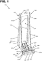
Figure 1 is a perspective view of a connection part that can be used to form an extendable patch panel having exemplary features of aspects in accordance with the principles of the present disclosure. -
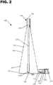
Figure 2 is a view of a first side of the connection part shown inFigure 1 . -
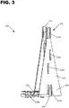
Figure 3 is a perspective view of a second side of the connection part shown inFigure 1 . -
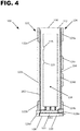
Figure 4 is a front view of the connection part shown inFigure 1 . -
Figure 5 is a rear view of the connection part shown inFigure 1 . -
Figure 6 is a top view of the connection part shown inFigure 1 . -
Figure 7 is a first perspective view of an adapter that can be used to form an extendable patch panel having exemplary features of aspects in accordance with the principles of the present disclosure. -
Figure 8 is a second perspective view of the adapter shown inFigure 7 . -
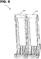
Figure 9 is a perspective view of a first extendable patch panel constructed from multiples of the connection part shown inFigure 1 . -
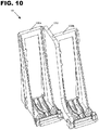
Figure 10 is a perspective view of a second extendable patch panel constructed from multiples of the connection part shown inFigure 1 and the adapter shown inFigure 7 . -
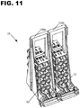
Figure 11 is a perspective view of the first extendable patch panel shown inFigure 9 with adapters installed into each connection part. -
Figure 12 is a bottom view of the first extendable patch panel shown inFigure 11 . -
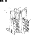
Figure 13 is a perspective view of the second extendable patch panel shown inFigure 10 with adapters installed into each connection part. -
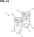
Figure 14 is a bottom view of the second extendable patch panel shown inFigure 13 . -
Figure 15 is a perspective view of a telecommunications tray including the first extendable patch panel shown inFigure 11 . - Reference will now be made in detail to the exemplary aspects of the present disclosure that are illustrated in the accompanying drawings. Wherever possible, the same reference numbers will be used throughout the drawings to refer to the same or like structure.
- Referring to
Figures 1-6 , aconnection part 100 of anextendable patch panel 10 is shown. In one aspect, theconnection part 100 defines afirst side 102, an oppositesecond side 104, atop end 106, and abottom end 108. Theconnection part 100 can also be defined as having afront end 103 and aback end 105. However, it is to be understood that terms such as "top", "bottom", "front", and "back" are simply used to provide a relative point of reference for the various features of theconnection part 100 and are not intended to require a particular orientation of theconnection part 100. - The
connection part 100 can be formed from abase portion 110 and anadjoining frame portion 112 extending between the first andsecond sides connection part 100 can be configured such that theframe portion 112 is disposed generally orthogonal to thebase portion 110, wherein thebase portion 110 defines thebottom end 108 of theconnection part 100 and theframe portion 112 defines thetop end 106 of theconnection part 100. Theframe portion 112 can be provided with anaperture 114 for holding a plurality oftelecommunications components 12, such as fiber optic adapters (seeFigures 11-15 ). - In one aspect, one or more
retaining protrusions 115 are provided extending from a side of the frame portion112 and into theaperture 114. Theretaining protrusions 115 allow for atelecommunications component 12 to be held in an upper part of theaperture 114 which can facilitate operator access to alower component 12 by allowing for the selective increasing of space between any twocomponents 12. As configured, theprotrusions 115 are provided with a rounded shape and deflect outward with theframe portion 112 as acomponent 12 is being moved past theprotrusion 115. Once acomponent 12 is moved above theprotrusion 115, theprotrusion 115 retains thecomponent 12 from below such that the component will not simply slide back in a downward direction. As shown, tworetaining protrusions 115 are provided in a frame configured to hold fourcomponents 12 below thelowermost protrusion 115. As such, the spacing between the top twocomponents 12 can be increased by raising the upper twocomponents 12 past the first orsecond protrusion 115. Theframe portion 112 can also be provided with athird retaining protrusion 115 if it is desired to retain the second tobottom component 12 in a raised position wherein the spacing is increased between the second tobottom component 12 and thebottom component 12. Likewise, theframe portion aperture 114 can be configured to store any number ofdesired components 12. - The
connection part 100 can be provided with various features that enhance the overall strength of theconnection part 100 and the joint between the base andframe portions connection part 100 can be provided with afirst sidewall 116 adjoining thefirst side 102 of theconnection part 100 at the base andframe portions connection part 100 can be provided with asecond sidewall 118 adjoining thesecond side 104 of theconnection part 100 at the base andframe portions connection part 100 may also be provided withsupport ribs 120a to 120f extending between thebase portion 110 and theframe portion 112. Thesidewalls ribs 120a to 120f significantly increase the structural integrity of theconnection part 100 which is advantageous asadapters 12 - In one aspect, the
connection part 100 can be provided with one or more connection features to enable theconnection parts 100 to be connected together in a side-by-side formation to form theextendable patch panel 10. As such, the number of interconnectedconnection parts 100 can be selected to obtain the desired size and length of thepatch panel 10. - In one example, a
first connection feature 122 can be provided on the first orsecond side connection part 100 and a cooperatingsecond connection feature 124 can be provided on the other of the first andsecond sides first connection feature 122 of oneconnection part 100a slidably engages with thesecond connection feature 124 of anadjacent connection part 100b. Such a configuration is shown atFigure 9 where twoconnection parts connection parts 100 can be joined together. The first and second connection features 122, 124 are configured such that they constrain the adjacent and interlockedconnection parts 100a,b from moving in a lateral direction (i.e. in a direction towards or away from the first andsecond sides back ends bottom ends - As shown, the
first connection feature 122 includes aconnection portion 122a proximate thetop end 106 of the connection part. Directly across from theconnection portion 122a, thesecond connection feature 124 is shown as including aconnection portion 124a. As shown, theconnection portions connection parts 100a,b are in a side-by-side arrangement with the front andback ends first connection feature 122 may also include aconnection portion 122b that is similar in construction toconnection portion 122a and may also include aconnection portion 124b that is similar in construction toconnection portion 124a. As shown, theconnection portions base portion 110 at thebottom end 108. In one aspect, the connection portions on eachside connection part 100 are coaxially aligned such thatconnection portions connection portions - In one aspect, the
connection portions connection portions connection portions connection portions connection portions - To aid in initial alignment of the
connection portions connection portions alignment structure 122c may be provided on thefirst side 102 of theconnection part 100 whileadditional alignment structures second side 104 of the connection part. As configured, thealignment structure 122c extends fully between theconnection portions alignment structures connection portions alignment structures connection parts 100 to be brought into initial alignment with each other such that theconnection portions connection portions connection part 100a with respect to anotherconnection part 100b along an axis parallel to the axis Z. In one aspect, thealignment structures connection parts 100a,b towards each other in a lateral direction parallel to the axis X. - With the above described configuration, one
connection part 100a can be aligned adjacent to anotherconnection part 100b with theconnection portions connection part 100a above or below theconnection portions adjacent connection part 100b. As stated previously, proper alignment of the connectingparts 100a,b is ensured by the prior engagement of thealignment structures upper connection part 100a can be displaced in a downward direction parallel to the axis Z until theconnection portion 122a slides into theconnection portion 124a and theconnection portion 122b slides into the connection portion 126b to lock theconnection parts 100a,b together at two distinct locations proximate theback end 105. This assembly process can be repeated until the desired number ofconnection parts 100 have been assembled together to form theextendable patch panel 10. - Each
connection part 100 may be additionally provided with athird connection feature 126 and afourth connection feature 128 to provide for an additional point of securement between adjoiningconnection parts 100 proximate thefront end 103. As shown, thethird connection feature 126 includes aconnection portion 126a that is provided on thebase portion 110 proximate thefront end 103. Similarly, thefourth connection feature 128 includes aconnection portion 128a provided on thebase portion 110 directly across from thethird connection feature 126. As shown, theconnection portions connection parts 100 are in a side-by-side arrangement with the front and back ends 103, 105 aligned along a common axis (e.g. an axis parallel to axis X). - In one aspect, the
connection portion 126a is formed as a male tail structure and theconnection portion 128a is formed as an open ended female socket structure into which theconnection portion 126a can slide to form a dovetail joint, in the same manner as already described forconnection portions 122a/124a and 122b/124b. It should be understood that a wide variety of interlocking shapes can be used for theconnection portions connection portions 122a/124a, 122b/124b, and 126a/128a provide for three points of contact or securement betweenadjacent connection parts 100. - Each
connection part 100 can also be provided with afirst lock feature 130 and asecond lock feature 140 to preventadjacent connection parts 100 from sliding out of engagement with each other in either direction along an axis parallel to axis Z once joined. In the example embodiment shown, thefirst lock feature 130 includes afirst spring clip 132 and afirst stop surface 134 at the connection partfirst side 102. Thespring clip 132 is provided with a free end 132a that is disposed above a notchedarea 136 of thebase portion 110. Similarly, thesecond lock feature 140 includes asecond spring clip 142 and a second stop surface 144 at the connection partsecond side 104, wherein thesecond spring clip 142 is provided with a free end 142a that is disposed above a notchedarea 146 of thebase portion 110. - The
first stop surface 134 is provided with a sufficient length such that thestop surface 134 of oneconnection part 100 extends into thenotch area 146 and below the free end 144a of anadjacent connection part 100. Likewise, the second stop surface 144 is provided with a sufficient length such that the stop surface 144 of oneconnection part 100 extends into thenotch area 136 and below the free end 132a of anadjacent connection part 100. Thus, an interference condition exists between the spring clips 132, 142 and therespective stop surface 134, 144. - As stated previously, two
connection parts 100a,b can be initially aligned with each other such that thesecond side 104 of afirst connection part 100a is adjacent to thefirst side 102 of asecond connection part 100b. In such an example, thefirst connection part 100a can be initially disposed above thesecond connection part 100b and then slid downwardly along an axis parallel to axis Z such that theconnection portions 122a/124a, 122b/124b, and 126a/128a become engaged. As theconnection parts 100 become fully aligned (e.g. the top ends 106 or bottom ends 108 are aligned), the second stop surface 144 of thefirst connection part 100a will initially engage with thefirst spring clip 132 of thesecond connection part 100b from above and force the spring clip free end 132a to deflect inwardly. As thefirst connection part 100a is further displaced downwardly, the spring clip free end 132a of thesecond connection part 100b will spring back or snap over the second stop surface 144 of thefirst stop surface 134 to prevent thefirst connection part 100a from subsequently being lifted back out of position in a direction towards thetop end 106. At the same time or near the same time, the free end 142a of thesecond spring clip 142 of thefirst connection part 100a comes into downward contact with thefirst stop surface 134 of thesecond connection part 100b to prevent thefirst connection part 100a from being further displaced downwardly with respect to thesecond connection part 100b. Thus, the spring clips 132,142 and stop surfaces 134,144, once engaged, entirely prevent theconnection part 100a from moving upwardly and downwardly along an axis parallel to the Z axis, thereby ensuring that theconnection portions 122a/124a, 122b/124b, and 126a/128a cannot become disengaged. If it is desired to disengage thefirst connection part 100a from thesecond connection part 100b, the spring clip free end 132a can be manually deflected inwardly beyond the reach of the stop surface 144 whereby thefirst connection part 100a can then be lifted upwardly and out of engagement with thesecond connection part 100b. Alternatively, thesecond spring clip 142 can be deflected inwardly beyond the reach of thestop surface 134 to allow thefirst connection part 100a to be displaced downwardly and out of engagement with thesecond connection part 100b. - As shown in
Figure 9 , the above described features result in anextendable patch panel 10 wherein each of theconnection parts 100 are aligned together such that the front and back ends 103,105 are fully aligned along a common plane. However, where a staggered orientation is preferred, the relative positions of the connection features 122, 124, 126, 128 and the lock features 130, 140 on eachside connection parts 100 can be offset on eachside connection parts 100 to achieve such a result. It is also noted that eachconnection part 100 can be integrally molded or otherwise formed such that all features of theconnection part 100 are formed as a single component. - A staggered configuration for an
extendable patch panel 10 can also be achieved using a plurality of the above describedconnection parts 100 with the introduction of anintermediate adapter 150. Theadapter 150 is shown atFigures 7-8 and a staggered configuration for apatch panel 10 is shown atFigures 9 and12 . To achieve this function, theadapter 150 replicates the connecting, aligning, and lock features of thefirst side 102 of theconnection part 100 on afirst side 152 of theadapter 150. Likewise, theadapter 150 replicates the connecting, aligning, and lock features of thesecond side 104 of theconnection part 100 on asecond side 154 of theadapter 150, but in an offset manner. - For example, the
first side 152 of theadapter 150 can be provided with thefirst connection feature 122 including theconnection portion 122a, theconnection portion 122b, and thealignment feature 122c. Thefirst side 152 can also be provided with thethird connection feature 126 including thethird connection portion 126a and can be further provided with the various components of thefirst lock feature 130. - The
second side 154 of theadapter 150 can be provided with thesecond connection feature 124 including theconnection portion 124a, theconnection portion 124b, and the alignment features 124c,d. Thesecond side 154 can also be provided with thefourth connection feature 128 including thefourth connection portion 128a. Thesecond side 154 can be further provided with the various components of thesecond lock feature 140, presented inFigure 8 aslock feature 160. As shown,lock feature 160 has astop surface 162 that performs the same general function as first stop surface 144 and engages with thespring clip 132 of theconnection part 100.Lock feature 160 can also be provided with anotherstop surface 164 that replaces thespring clip 142 and engages with thestop surface 134 of theconnection part 100 to prevent further downward movement of theadapter 150 with respect to theconnection part 100. As such, lock feature 160 of theadapter 150 interacts withlock feature 130 of the connection part to secure theadapter 150 to theconnection part 100. - Referring to
Figures 11-12 , a fully assembledpatch panel 10 havingconnection parts connection parts 100 are shown, any number of desiredconnection parts 100 can be joined together. As shown, theconnection parts connection parts fiber optic adapters 12. Referring toFigure 15 , the fully assembledpatch panel 10 is shown as being installed in atelecommunications enclosure 200 which may be configured to holdother telecommunications components 202. As will be appreciated by one having skill in the art, thetelecommunications enclosure 200 shown inFigure 15 may be provided with a cover (not shown) and cable seals (not shown) to form an enclosed housing. The base 20 can be configured with a mounting surface 22 to provide a support surface for mountingtelecommunications components 202, such as telecommunications cables, connectivity equipment, splices, splitters, wave division multiplexers, and terminations. - Referring to
Figures 13-14 , a staggered arrangement of a fully assembledpatch panel 10 is shown havingconnection parts adapter 150. Although two joinedconnection parts 100 and asingle adapter 150 are shown, any number of desiredconnection parts 100 andadapters 150 can be joined together. As shown, theconnection parts connection parts fiber optic adapters 12. - Various modifications and alterations of this disclosure will become apparent to those skilled in the art without departing from the scope and of this disclosure, and it should be understood that the scope of this disclosure is not to be unduly limited to the illustrative embodiments set forth herein.
PARTS LIST 10 extendable patch panel 126 third connection feature 12 adapters 126a third connection portion 100 connection part 128 fourth connection feature 102 first side 128a fourth connection portion 103 front end 130 first lock feature 104 second side 132 first spring clip 105 back end 132a first spring clip free end 106 top end 134 first stop surface 108 bottom end 136 notched area in base 110 base portion 140 second lock feature 112 frame portion 142 second spring clip 114 aperture 142a second spring clip free end 115 retaining protrusions 116 first sidewall 144 second stop surface 118 second sidewall 146 notched area in base 120a- f support ribs 150 adapter part 122 first connection feature 152 first side 122a connection portion 154 second side 122b connection portion 156 stop 122c alignment structure 160 third lock feature 124 second connection feature 162 stop surface 124a connection portion 164 stop surface 124b connection portion 200 telecommunications enclosure 124c alignment structure 124d alignment structure
Claims (11)
- An extendable telecommunications patch panel (10) comprising:a. a plurality of interconnectable connection parts (100), each of the connection parts (100) having a first side (102), a second side (104), a top end (106), and a bottom end (108) and including:i. a base portion (110) located at the bottom end (108) and extending between the first and second sides (102, 104);ii. a frame portion (112) extending from the base portion (110) to the top end (106), the frame portion (112) extending between the first and second sides (102, 104), the frame portion (112) defining an aperture (114) for receiving one or more fiber optic adapters (12);iii. a first connection feature (122) located on the connection part first side (102); andiv. a second connection feature (124) located on the connection part second side (104);v. the first connection feature (122) being configured to interlock with the second connection feature (124) of an adjacent connection part (100), the patch panel characterised by comprising an adapter (150) configured for attachment to the first side (102) of the connection part (100) and attachment to the second side (104) of an adjacent connection part (100).
- The extendable telecommunications patch panel (10) of claim 1, wherein:a. the first connection feature (122) includes a first connection portion (122a) and a second connection portion (122b); andb. the second connection feature (124) includes a third connection portion (124a) and a fourth connection portion (124b);c. wherein the first connection portion (122a) is configured to slidably engage with the third connection portion (124a) of an adjacent connection part (100);d. the second connection portion (122b) being configured to slidably engage with the fourth connection portion (124b) of the adjacent connection part (100).
- The extendable telecommunications patch panel (10) of any preceding claim, further comprising:a. a first alignment structure (122c) located on the connection part first side (102); andb. a second alignment structure (124c, 124d) located on the connection part second side (104);c. the first alignment structure (122c) being configured to engage with the second alignment structure (124c, 124d) of an adjacent connection part (100) to guide the first and second connection features (122, 124) into engagement;d. the first and second connection portions (122a, 122b) are configured as male tail portions and the third and fourth connection portions (124c, 124d) are configured as female socket portions to form a dovetail-type connection; ande. the first alignment structure (122c) is configured as a continuous rib extending between the first and second connection portion s (122a, 122b).
- The extendable telecommunications patch panel (10) of any preceding claim, further comprising:a. a third connection feature (126) located on the connection part first side (102); andb. a fourth connection feature (128) located on the connection part second side (104);c. the third connection feature (126) being configured to interlock with the fourth connection feature (128) of an adjacent connection part.
- The extendable telecommunications patch panel (10) of any preceding claim, further comprising:a. a first lock feature (130) located on the connection part first side (102); andb. a second lock feature (140) located on the connection part second side (104);c. the first lock feature (130) being configured to engage with the second lock feature (140) of an adjacent connection part (100) to lock adjacent connection parts (100) together;d. the first lock feature (130) includes a first spring clip (132) and a first stop surface (134);e. the second lock feature (140) includes a second spring clip (142) and a second stop surface (144);f. the first spring clip (132) is configured to engage with the second stop surface (144) of an adjacent connection part (100); andg. the second spring clip (142) is configured to engage with the first stop surface (134) of the adjacent connection part (100).
- The extendable telecommunications patch panel (10) of any preceding claim, wherein:a. the first connection feature (122) is located directly across from the second connection feature (124) such that the first and second connection features (122, 124) are disposed along a common plane.
- The extendable telecommunications patch panel (10) of claim 1, wherein:a. the adapter (150) is provided with a first adapter connection feature (122) on a first side (152), the first adapter connection feature (122) being configured to engage with the second connection feature (124) of the connection part (100); andb. the adapter (150) is provided with a second adapter connection feature (124) on a second side (154), the second adapter connection feature (124) being configured to engage with the first connection feature (122) of an adjacent connection part (100).
- The extendable telecommunications patch panel (10) of claim 7, wherein:a. the first adapter connection feature (124) is offset from the second adapter connection feature (126) to result in a staggered patch panel configuration.
- The extendable telecommunications patch panel (10) of any preceding claim, further comprising:a. a plurality of fiber optic adapters (12) retained in each of the connection parts (100).
- A method of building an extendable patch panel (10) including the steps of:a. providing a plurality of interconnectable connection parts (100a,b), each of the connection parts (100) having a first side (102), a second side (104), a top end (106), and a bottom end (108) and including:i. a base portion (110) located at the bottom end (108) and extending between the first and second sides (102, 104);ii. a frame portion (112) extending from the base portion (110) to the top end (106), the frame portion (102) extending between the first and second sides (102, 104);iii. a first connection feature (122) located on the connection part first side (102); andiv. a second connection feature (124) located on the connection part second side (104);b. providing an adapter (150) having a first adapter connection feature (122) and a second adapter connection feature (124);c. aligning the first connection feature (122) of the first connection part (100a) with the second adapter connection feature (124) of the adapter (150); andd. attaching the first connection part (100a) with the adapter (150) by sliding the first connection feature (122) of the first connection part (100a) into engagement with the second adapter connection feature (124) of the adapter (150).
- The method of building an extendable patch panel (10) of claim 10, further including the step of:a. aligning the second connection feature (124) of the second connection part (100b) with the first adapter connection feature (122) of the adapter (150); andb. attaching the second connection part (100b) with the adapter (150) by sliding the second connection feature (124) of the second connection part (100b) into engagement with the first adapter connection feature (122) of the adapter (150).
Applications Claiming Priority (2)
| Application Number | Priority Date | Filing Date | Title |
|---|---|---|---|
| US201462088347P | 2014-12-05 | 2014-12-05 | |
| PCT/EP2015/078735 WO2016087669A1 (en) | 2014-12-05 | 2015-12-04 | Extendable patch panel |
Publications (2)
| Publication Number | Publication Date |
|---|---|
| EP3228091A1 EP3228091A1 (en) | 2017-10-11 |
| EP3228091B1 true EP3228091B1 (en) | 2019-07-24 |
Family
ID=54834815
Family Applications (1)
| Application Number | Title | Priority Date | Filing Date |
|---|---|---|---|
| EP15805469.2A Active EP3228091B1 (en) | 2014-12-05 | 2015-12-04 | Extendable patch panel |
Country Status (7)
| Country | Link |
|---|---|
| US (3) | US10506306B2 (en) |
| EP (1) | EP3228091B1 (en) |
| AU (1) | AU2015357055B2 (en) |
| ES (1) | ES2748698T3 (en) |
| HU (1) | HUE046928T2 (en) |
| WO (1) | WO2016087669A1 (en) |
| ZA (1) | ZA201704363B (en) |
Families Citing this family (1)
| Publication number | Priority date | Publication date | Assignee | Title |
|---|---|---|---|---|
| ES2748698T3 (en) * | 2014-12-05 | 2020-03-17 | CommScope Connectivity Belgium BVBA | Expandable patch panel |
Family Cites Families (9)
| Publication number | Priority date | Publication date | Assignee | Title |
|---|---|---|---|---|
| TW232757B (en) | 1994-01-21 | 1994-10-21 | Adc Telecommunications Inc | High-density fiber distribution frame |
| US6591051B2 (en) | 2001-11-16 | 2003-07-08 | Adc Telecommunications, Inc. | Fiber termination block with angled slide |
| US7086539B2 (en) | 2002-10-21 | 2006-08-08 | Adc Telecommunications, Inc. | High density panel with rotating tray |
| US7220145B2 (en) * | 2004-04-14 | 2007-05-22 | Tyco Electronics Corporation | Patch panel system |
| US9261654B2 (en) * | 2009-10-13 | 2016-02-16 | Leviton Manufacturing Co., Inc. | Fiber optic adapter plates with integrated fiber optic adapters |
| JP5518979B2 (en) * | 2012-11-09 | 2014-06-11 | 株式会社フジクラ | Optical connector receptacle, receptacle housing, optical connector adapter, adapter housing |
| US9268103B2 (en) * | 2013-05-10 | 2016-02-23 | Senko Advanced Components, Inc. | Interlockable fiber optic connector adaptors |
| WO2015034811A1 (en) * | 2013-09-06 | 2015-03-12 | Corning Optical Communications LLC | Optical fiber cassette systems with fiber retaining covers |
| ES2748698T3 (en) * | 2014-12-05 | 2020-03-17 | CommScope Connectivity Belgium BVBA | Expandable patch panel |
-
2015
- 2015-12-04 ES ES15805469T patent/ES2748698T3/en active Active
- 2015-12-04 EP EP15805469.2A patent/EP3228091B1/en active Active
- 2015-12-04 HU HUE15805469A patent/HUE046928T2/en unknown
- 2015-12-04 WO PCT/EP2015/078735 patent/WO2016087669A1/en not_active Ceased
- 2015-12-04 US US15/532,908 patent/US10506306B2/en active Active
- 2015-12-04 AU AU2015357055A patent/AU2015357055B2/en not_active Ceased
-
2017
- 2017-06-27 ZA ZA2017/04363A patent/ZA201704363B/en unknown
-
2019
- 2019-11-14 US US16/683,965 patent/US11218785B2/en active Active
-
2022
- 2022-01-03 US US17/567,568 patent/US20220272426A1/en not_active Abandoned
Non-Patent Citations (1)
| Title |
|---|
| None * |
Also Published As
| Publication number | Publication date |
|---|---|
| US10506306B2 (en) | 2019-12-10 |
| AU2015357055B2 (en) | 2019-10-31 |
| US20170366874A1 (en) | 2017-12-21 |
| US11218785B2 (en) | 2022-01-04 |
| ZA201704363B (en) | 2021-01-27 |
| EP3228091A1 (en) | 2017-10-11 |
| US20220272426A1 (en) | 2022-08-25 |
| US20200154179A1 (en) | 2020-05-14 |
| AU2015357055A1 (en) | 2017-06-29 |
| ES2748698T3 (en) | 2020-03-17 |
| HUE046928T2 (en) | 2020-03-30 |
| WO2016087669A1 (en) | 2016-06-09 |
Similar Documents
| Publication | Publication Date | Title |
|---|---|---|
| AU2023200219B2 (en) | A high density patch panel with modular cassettes | |
| US6118075A (en) | Stackable universal pitch cable trough system | |
| EP4001983B1 (en) | Fiber optic cassette system mounting system | |
| US10598884B2 (en) | Fiber optic cassette system with releasable engagement | |
| CN101304166B (en) | Protector | |
| US8315497B2 (en) | Universal sliding adapter pack | |
| US8958679B2 (en) | Fibre-optic telecommunications module | |
| WO2009058758A1 (en) | Sliding adapter panel with living hinge and forward/rearward locking | |
| WO2013055714A1 (en) | Receptacle connector having internal latching mechanism | |
| US20120141070A1 (en) | Connector assembly with improved structure on a bracket for mounting connectors | |
| US20110111646A1 (en) | Fanning module, fanning strip, and cable management panel | |
| CN107623878B (en) | Finger clip type cable management assembly | |
| US20220272426A1 (en) | Extendable patch panel | |
| US20210112678A1 (en) | Modular telecommunications patch panel system | |
| EP4266103B1 (en) | Fiber optic connector assembly | |
| WO2017064278A1 (en) | System for cable storage and device mounting parts |
Legal Events
| Date | Code | Title | Description |
|---|---|---|---|
| STAA | Information on the status of an ep patent application or granted ep patent |
Free format text: STATUS: THE INTERNATIONAL PUBLICATION HAS BEEN MADE |
|
| PUAI | Public reference made under article 153(3) epc to a published international application that has entered the european phase |
Free format text: ORIGINAL CODE: 0009012 |
|
| STAA | Information on the status of an ep patent application or granted ep patent |
Free format text: STATUS: REQUEST FOR EXAMINATION WAS MADE |
|
| 17P | Request for examination filed |
Effective date: 20170606 |
|
| AK | Designated contracting states |
Kind code of ref document: A1 Designated state(s): AL AT BE BG CH CY CZ DE DK EE ES FI FR GB GR HR HU IE IS IT LI LT LU LV MC MK MT NL NO PL PT RO RS SE SI SK SM TR |
|
| AX | Request for extension of the european patent |
Extension state: BA ME |
|
| RIN1 | Information on inventor provided before grant (corrected) |
Inventor name: AMBROZ, JIRI Inventor name: SCHURMANS, ERIC Inventor name: ZAVREL, JIRI |
|
| RIN1 | Information on inventor provided before grant (corrected) |
Inventor name: ZAVREL, JIRI Inventor name: SCHURMANS, ERIC Inventor name: AMBROZ, JIRI |
|
| DAV | Request for validation of the european patent (deleted) | ||
| DAX | Request for extension of the european patent (deleted) | ||
| GRAP | Despatch of communication of intention to grant a patent |
Free format text: ORIGINAL CODE: EPIDOSNIGR1 |
|
| STAA | Information on the status of an ep patent application or granted ep patent |
Free format text: STATUS: GRANT OF PATENT IS INTENDED |
|
| INTG | Intention to grant announced |
Effective date: 20180924 |
|
| GRAJ | Information related to disapproval of communication of intention to grant by the applicant or resumption of examination proceedings by the epo deleted |
Free format text: ORIGINAL CODE: EPIDOSDIGR1 |
|
| STAA | Information on the status of an ep patent application or granted ep patent |
Free format text: STATUS: REQUEST FOR EXAMINATION WAS MADE |
|
| GRAP | Despatch of communication of intention to grant a patent |
Free format text: ORIGINAL CODE: EPIDOSNIGR1 |
|
| STAA | Information on the status of an ep patent application or granted ep patent |
Free format text: STATUS: GRANT OF PATENT IS INTENDED |
|
| INTC | Intention to grant announced (deleted) | ||
| INTG | Intention to grant announced |
Effective date: 20190222 |
|
| GRAS | Grant fee paid |
Free format text: ORIGINAL CODE: EPIDOSNIGR3 |
|
| GRAA | (expected) grant |
Free format text: ORIGINAL CODE: 0009210 |
|
| STAA | Information on the status of an ep patent application or granted ep patent |
Free format text: STATUS: THE PATENT HAS BEEN GRANTED |
|
| AK | Designated contracting states |
Kind code of ref document: B1 Designated state(s): AL AT BE BG CH CY CZ DE DK EE ES FI FR GB GR HR HU IE IS IT LI LT LU LV MC MK MT NL NO PL PT RO RS SE SI SK SM TR |
|
| REG | Reference to a national code |
Ref country code: GB Ref legal event code: FG4D |
|
| REG | Reference to a national code |
Ref country code: CH Ref legal event code: EP |
|
| REG | Reference to a national code |
Ref country code: DE Ref legal event code: R096 Ref document number: 602015034439 Country of ref document: DE |
|
| REG | Reference to a national code |
Ref country code: AT Ref legal event code: REF Ref document number: 1159711 Country of ref document: AT Kind code of ref document: T Effective date: 20190815 |
|
| REG | Reference to a national code |
Ref country code: IE Ref legal event code: FG4D |
|
| REG | Reference to a national code |
Ref country code: NL Ref legal event code: MP Effective date: 20190724 |
|
| REG | Reference to a national code |
Ref country code: LT Ref legal event code: MG4D |
|
| REG | Reference to a national code |
Ref country code: AT Ref legal event code: MK05 Ref document number: 1159711 Country of ref document: AT Kind code of ref document: T Effective date: 20190724 |
|
| PG25 | Lapsed in a contracting state [announced via postgrant information from national office to epo] |
Ref country code: AT Free format text: LAPSE BECAUSE OF FAILURE TO SUBMIT A TRANSLATION OF THE DESCRIPTION OR TO PAY THE FEE WITHIN THE PRESCRIBED TIME-LIMIT Effective date: 20190724 Ref country code: NO Free format text: LAPSE BECAUSE OF FAILURE TO SUBMIT A TRANSLATION OF THE DESCRIPTION OR TO PAY THE FEE WITHIN THE PRESCRIBED TIME-LIMIT Effective date: 20191024 Ref country code: SE Free format text: LAPSE BECAUSE OF FAILURE TO SUBMIT A TRANSLATION OF THE DESCRIPTION OR TO PAY THE FEE WITHIN THE PRESCRIBED TIME-LIMIT Effective date: 20190724 Ref country code: FI Free format text: LAPSE BECAUSE OF FAILURE TO SUBMIT A TRANSLATION OF THE DESCRIPTION OR TO PAY THE FEE WITHIN THE PRESCRIBED TIME-LIMIT Effective date: 20190724 Ref country code: HR Free format text: LAPSE BECAUSE OF FAILURE TO SUBMIT A TRANSLATION OF THE DESCRIPTION OR TO PAY THE FEE WITHIN THE PRESCRIBED TIME-LIMIT Effective date: 20190724 Ref country code: BG Free format text: LAPSE BECAUSE OF FAILURE TO SUBMIT A TRANSLATION OF THE DESCRIPTION OR TO PAY THE FEE WITHIN THE PRESCRIBED TIME-LIMIT Effective date: 20191024 Ref country code: NL Free format text: LAPSE BECAUSE OF FAILURE TO SUBMIT A TRANSLATION OF THE DESCRIPTION OR TO PAY THE FEE WITHIN THE PRESCRIBED TIME-LIMIT Effective date: 20190724 Ref country code: PT Free format text: LAPSE BECAUSE OF FAILURE TO SUBMIT A TRANSLATION OF THE DESCRIPTION OR TO PAY THE FEE WITHIN THE PRESCRIBED TIME-LIMIT Effective date: 20191125 Ref country code: LT Free format text: LAPSE BECAUSE OF FAILURE TO SUBMIT A TRANSLATION OF THE DESCRIPTION OR TO PAY THE FEE WITHIN THE PRESCRIBED TIME-LIMIT Effective date: 20190724 |
|
| PG25 | Lapsed in a contracting state [announced via postgrant information from national office to epo] |
Ref country code: AL Free format text: LAPSE BECAUSE OF FAILURE TO SUBMIT A TRANSLATION OF THE DESCRIPTION OR TO PAY THE FEE WITHIN THE PRESCRIBED TIME-LIMIT Effective date: 20190724 Ref country code: GR Free format text: LAPSE BECAUSE OF FAILURE TO SUBMIT A TRANSLATION OF THE DESCRIPTION OR TO PAY THE FEE WITHIN THE PRESCRIBED TIME-LIMIT Effective date: 20191025 Ref country code: LV Free format text: LAPSE BECAUSE OF FAILURE TO SUBMIT A TRANSLATION OF THE DESCRIPTION OR TO PAY THE FEE WITHIN THE PRESCRIBED TIME-LIMIT Effective date: 20190724 Ref country code: IS Free format text: LAPSE BECAUSE OF FAILURE TO SUBMIT A TRANSLATION OF THE DESCRIPTION OR TO PAY THE FEE WITHIN THE PRESCRIBED TIME-LIMIT Effective date: 20191124 Ref country code: RS Free format text: LAPSE BECAUSE OF FAILURE TO SUBMIT A TRANSLATION OF THE DESCRIPTION OR TO PAY THE FEE WITHIN THE PRESCRIBED TIME-LIMIT Effective date: 20190724 |
|
| REG | Reference to a national code |
Ref country code: ES Ref legal event code: FG2A Ref document number: 2748698 Country of ref document: ES Kind code of ref document: T3 Effective date: 20200317 |
|
| REG | Reference to a national code |
Ref country code: HU Ref legal event code: AG4A Ref document number: E046928 Country of ref document: HU |
|
| PG25 | Lapsed in a contracting state [announced via postgrant information from national office to epo] |
Ref country code: TR Free format text: LAPSE BECAUSE OF FAILURE TO SUBMIT A TRANSLATION OF THE DESCRIPTION OR TO PAY THE FEE WITHIN THE PRESCRIBED TIME-LIMIT Effective date: 20190724 |
|
| PG25 | Lapsed in a contracting state [announced via postgrant information from national office to epo] |
Ref country code: RO Free format text: LAPSE BECAUSE OF FAILURE TO SUBMIT A TRANSLATION OF THE DESCRIPTION OR TO PAY THE FEE WITHIN THE PRESCRIBED TIME-LIMIT Effective date: 20190724 Ref country code: PL Free format text: LAPSE BECAUSE OF FAILURE TO SUBMIT A TRANSLATION OF THE DESCRIPTION OR TO PAY THE FEE WITHIN THE PRESCRIBED TIME-LIMIT Effective date: 20190724 Ref country code: DK Free format text: LAPSE BECAUSE OF FAILURE TO SUBMIT A TRANSLATION OF THE DESCRIPTION OR TO PAY THE FEE WITHIN THE PRESCRIBED TIME-LIMIT Effective date: 20190724 Ref country code: EE Free format text: LAPSE BECAUSE OF FAILURE TO SUBMIT A TRANSLATION OF THE DESCRIPTION OR TO PAY THE FEE WITHIN THE PRESCRIBED TIME-LIMIT Effective date: 20190724 |
|
| PG25 | Lapsed in a contracting state [announced via postgrant information from national office to epo] |
Ref country code: CZ Free format text: LAPSE BECAUSE OF FAILURE TO SUBMIT A TRANSLATION OF THE DESCRIPTION OR TO PAY THE FEE WITHIN THE PRESCRIBED TIME-LIMIT Effective date: 20190724 Ref country code: SM Free format text: LAPSE BECAUSE OF FAILURE TO SUBMIT A TRANSLATION OF THE DESCRIPTION OR TO PAY THE FEE WITHIN THE PRESCRIBED TIME-LIMIT Effective date: 20190724 Ref country code: IS Free format text: LAPSE BECAUSE OF FAILURE TO SUBMIT A TRANSLATION OF THE DESCRIPTION OR TO PAY THE FEE WITHIN THE PRESCRIBED TIME-LIMIT Effective date: 20200224 Ref country code: SK Free format text: LAPSE BECAUSE OF FAILURE TO SUBMIT A TRANSLATION OF THE DESCRIPTION OR TO PAY THE FEE WITHIN THE PRESCRIBED TIME-LIMIT Effective date: 20190724 |
|
| REG | Reference to a national code |
Ref country code: DE Ref legal event code: R097 Ref document number: 602015034439 Country of ref document: DE |
|
| PLBE | No opposition filed within time limit |
Free format text: ORIGINAL CODE: 0009261 |
|
| STAA | Information on the status of an ep patent application or granted ep patent |
Free format text: STATUS: NO OPPOSITION FILED WITHIN TIME LIMIT |
|
| PG2D | Information on lapse in contracting state deleted |
Ref country code: IS |
|
| REG | Reference to a national code |
Ref country code: CH Ref legal event code: PL |
|
| 26N | No opposition filed |
Effective date: 20200603 |
|
| REG | Reference to a national code |
Ref country code: BE Ref legal event code: MM Effective date: 20191231 |
|
| PG25 | Lapsed in a contracting state [announced via postgrant information from national office to epo] |
Ref country code: MC Free format text: LAPSE BECAUSE OF FAILURE TO SUBMIT A TRANSLATION OF THE DESCRIPTION OR TO PAY THE FEE WITHIN THE PRESCRIBED TIME-LIMIT Effective date: 20190724 Ref country code: SI Free format text: LAPSE BECAUSE OF FAILURE TO SUBMIT A TRANSLATION OF THE DESCRIPTION OR TO PAY THE FEE WITHIN THE PRESCRIBED TIME-LIMIT Effective date: 20190724 |
|
| PG25 | Lapsed in a contracting state [announced via postgrant information from national office to epo] |
Ref country code: LU Free format text: LAPSE BECAUSE OF NON-PAYMENT OF DUE FEES Effective date: 20191204 Ref country code: IE Free format text: LAPSE BECAUSE OF NON-PAYMENT OF DUE FEES Effective date: 20191204 |
|
| PG25 | Lapsed in a contracting state [announced via postgrant information from national office to epo] |
Ref country code: CH Free format text: LAPSE BECAUSE OF NON-PAYMENT OF DUE FEES Effective date: 20191231 Ref country code: BE Free format text: LAPSE BECAUSE OF NON-PAYMENT OF DUE FEES Effective date: 20191231 Ref country code: LI Free format text: LAPSE BECAUSE OF NON-PAYMENT OF DUE FEES Effective date: 20191231 |
|
| PG25 | Lapsed in a contracting state [announced via postgrant information from national office to epo] |
Ref country code: CY Free format text: LAPSE BECAUSE OF FAILURE TO SUBMIT A TRANSLATION OF THE DESCRIPTION OR TO PAY THE FEE WITHIN THE PRESCRIBED TIME-LIMIT Effective date: 20190724 |
|
| PG25 | Lapsed in a contracting state [announced via postgrant information from national office to epo] |
Ref country code: MT Free format text: LAPSE BECAUSE OF FAILURE TO SUBMIT A TRANSLATION OF THE DESCRIPTION OR TO PAY THE FEE WITHIN THE PRESCRIBED TIME-LIMIT Effective date: 20190724 |
|
| PG25 | Lapsed in a contracting state [announced via postgrant information from national office to epo] |
Ref country code: MK Free format text: LAPSE BECAUSE OF FAILURE TO SUBMIT A TRANSLATION OF THE DESCRIPTION OR TO PAY THE FEE WITHIN THE PRESCRIBED TIME-LIMIT Effective date: 20190724 |
|
| PGFP | Annual fee paid to national office [announced via postgrant information from national office to epo] |
Ref country code: HU Payment date: 20221129 Year of fee payment: 8 |
|
| P01 | Opt-out of the competence of the unified patent court (upc) registered |
Effective date: 20230530 |
|
| PG25 | Lapsed in a contracting state [announced via postgrant information from national office to epo] |
Ref country code: HU Free format text: LAPSE BECAUSE OF NON-PAYMENT OF DUE FEES Effective date: 20231205 |
|
| PG25 | Lapsed in a contracting state [announced via postgrant information from national office to epo] |
Ref country code: HU Free format text: LAPSE BECAUSE OF NON-PAYMENT OF DUE FEES Effective date: 20231205 |
|
| PGFP | Annual fee paid to national office [announced via postgrant information from national office to epo] |
Ref country code: GB Payment date: 20251229 Year of fee payment: 11 |
|
| PGFP | Annual fee paid to national office [announced via postgrant information from national office to epo] |
Ref country code: IT Payment date: 20251219 Year of fee payment: 11 |
|
| PGFP | Annual fee paid to national office [announced via postgrant information from national office to epo] |
Ref country code: FR Payment date: 20251226 Year of fee payment: 11 |
|
| PGFP | Annual fee paid to national office [announced via postgrant information from national office to epo] |
Ref country code: ES Payment date: 20260102 Year of fee payment: 11 |
|
| PGFP | Annual fee paid to national office [announced via postgrant information from national office to epo] |
Ref country code: DE Payment date: 20251229 Year of fee payment: 11 |