EP3226531A1 - Image forming device with halftoning selection process - Google Patents
Image forming device with halftoning selection process Download PDFInfo
- Publication number
- EP3226531A1 EP3226531A1 EP17163312.6A EP17163312A EP3226531A1 EP 3226531 A1 EP3226531 A1 EP 3226531A1 EP 17163312 A EP17163312 A EP 17163312A EP 3226531 A1 EP3226531 A1 EP 3226531A1
- Authority
- EP
- European Patent Office
- Prior art keywords
- image data
- binarized image
- forming device
- image forming
- error
- Prior art date
- Legal status (The legal status is an assumption and is not a legal conclusion. Google has not performed a legal analysis and makes no representation as to the accuracy of the status listed.)
- Withdrawn
Links
- 238000000034 method Methods 0.000 title claims description 106
- 238000009792 diffusion process Methods 0.000 claims description 6
- 238000010586 diagram Methods 0.000 description 17
- 239000011159 matrix material Substances 0.000 description 17
- 230000000694 effects Effects 0.000 description 3
- 230000002093 peripheral effect Effects 0.000 description 2
- 239000000463 material Substances 0.000 description 1
Images




Classifications
-
- H—ELECTRICITY
- H04—ELECTRIC COMMUNICATION TECHNIQUE
- H04N—PICTORIAL COMMUNICATION, e.g. TELEVISION
- H04N1/00—Scanning, transmission or reproduction of documents or the like, e.g. facsimile transmission; Details thereof
- H04N1/40—Picture signal circuits
- H04N1/405—Halftoning, i.e. converting the picture signal of a continuous-tone original into a corresponding signal showing only two levels
-
- H—ELECTRICITY
- H04—ELECTRIC COMMUNICATION TECHNIQUE
- H04N—PICTORIAL COMMUNICATION, e.g. TELEVISION
- H04N1/00—Scanning, transmission or reproduction of documents or the like, e.g. facsimile transmission; Details thereof
- H04N1/00002—Diagnosis, testing or measuring; Detecting, analysing or monitoring not otherwise provided for
- H04N1/00005—Diagnosis, testing or measuring; Detecting, analysing or monitoring not otherwise provided for relating to image data
-
- H—ELECTRICITY
- H04—ELECTRIC COMMUNICATION TECHNIQUE
- H04N—PICTORIAL COMMUNICATION, e.g. TELEVISION
- H04N1/00—Scanning, transmission or reproduction of documents or the like, e.g. facsimile transmission; Details thereof
- H04N1/00002—Diagnosis, testing or measuring; Detecting, analysing or monitoring not otherwise provided for
- H04N1/00026—Methods therefor
- H04N1/00031—Testing, i.e. determining the result of a trial
-
- H—ELECTRICITY
- H04—ELECTRIC COMMUNICATION TECHNIQUE
- H04N—PICTORIAL COMMUNICATION, e.g. TELEVISION
- H04N1/00—Scanning, transmission or reproduction of documents or the like, e.g. facsimile transmission; Details thereof
- H04N1/00002—Diagnosis, testing or measuring; Detecting, analysing or monitoring not otherwise provided for
- H04N1/00026—Methods therefor
- H04N1/00068—Calculating or estimating
-
- H—ELECTRICITY
- H04—ELECTRIC COMMUNICATION TECHNIQUE
- H04N—PICTORIAL COMMUNICATION, e.g. TELEVISION
- H04N1/00—Scanning, transmission or reproduction of documents or the like, e.g. facsimile transmission; Details thereof
- H04N1/40—Picture signal circuits
- H04N1/40093—Modification of content of picture, e.g. retouching
-
- H—ELECTRICITY
- H04—ELECTRIC COMMUNICATION TECHNIQUE
- H04N—PICTORIAL COMMUNICATION, e.g. TELEVISION
- H04N1/00—Scanning, transmission or reproduction of documents or the like, e.g. facsimile transmission; Details thereof
- H04N1/40—Picture signal circuits
- H04N1/405—Halftoning, i.e. converting the picture signal of a continuous-tone original into a corresponding signal showing only two levels
- H04N1/4051—Halftoning, i.e. converting the picture signal of a continuous-tone original into a corresponding signal showing only two levels producing a dispersed dots halftone pattern, the dots having substantially the same size
- H04N1/4052—Halftoning, i.e. converting the picture signal of a continuous-tone original into a corresponding signal showing only two levels producing a dispersed dots halftone pattern, the dots having substantially the same size by error diffusion, i.e. transferring the binarising error to neighbouring dot decisions
-
- H—ELECTRICITY
- H04—ELECTRIC COMMUNICATION TECHNIQUE
- H04N—PICTORIAL COMMUNICATION, e.g. TELEVISION
- H04N1/00—Scanning, transmission or reproduction of documents or the like, e.g. facsimile transmission; Details thereof
- H04N1/40—Picture signal circuits
- H04N1/405—Halftoning, i.e. converting the picture signal of a continuous-tone original into a corresponding signal showing only two levels
- H04N1/4051—Halftoning, i.e. converting the picture signal of a continuous-tone original into a corresponding signal showing only two levels producing a dispersed dots halftone pattern, the dots having substantially the same size
- H04N1/4052—Halftoning, i.e. converting the picture signal of a continuous-tone original into a corresponding signal showing only two levels producing a dispersed dots halftone pattern, the dots having substantially the same size by error diffusion, i.e. transferring the binarising error to neighbouring dot decisions
- H04N1/4053—Halftoning, i.e. converting the picture signal of a continuous-tone original into a corresponding signal showing only two levels producing a dispersed dots halftone pattern, the dots having substantially the same size by error diffusion, i.e. transferring the binarising error to neighbouring dot decisions with threshold modulated relative to input image data or vice versa
-
- H—ELECTRICITY
- H04—ELECTRIC COMMUNICATION TECHNIQUE
- H04N—PICTORIAL COMMUNICATION, e.g. TELEVISION
- H04N1/00—Scanning, transmission or reproduction of documents or the like, e.g. facsimile transmission; Details thereof
- H04N1/40—Picture signal circuits
- H04N1/40062—Discrimination between different image types, e.g. two-tone, continuous tone
-
- H—ELECTRICITY
- H04—ELECTRIC COMMUNICATION TECHNIQUE
- H04N—PICTORIAL COMMUNICATION, e.g. TELEVISION
- H04N1/00—Scanning, transmission or reproduction of documents or the like, e.g. facsimile transmission; Details thereof
- H04N1/46—Colour picture communication systems
- H04N1/52—Circuits or arrangements for halftone screening
Definitions
- Inkjet printers, laser printers, etc. are known as image forming devices or printing devices that print binarized image data by forming a large number of dots on paper.
- Such printing devices change the number of dots formed in a certain area on the paper, so as to represent a pseudo-intermediate gradation of the binarized image data (refer to Patent Literature 1: Japanese Patent Publication No. 2007-67984 , for example).
- the binarized image data including black pixels that form the dots and white pixels that do not form the dots, is generated by executing a halftone process on each pixel value of multiple pixels included in multi-gradation original image data.
- the aforementioned halftone process has several types, such as halftone process by a dither method, halftone process by an error diffusion method, and so on.
- the image quality of the binarized image data may vary due to compatibility between the original image data and the type of the halftone process.
- the invention provides a printing device that is capable of suppressing the unevenness in the image quality of the binarized image data.
- the disclosure provides a printing device, including a generation part, a determination part and a printing part.
- the generation part generates a plurality of types of binarized image data with respect to original image data.
- the determination part determines the binarized image data, in which an error between each of the plurality of the types of the binarized image data and the original image data is smaller, among the plurality of the types of the binarized image data.
- the printing part prints the binarized image data determined by the determination part on a medium.
- the image forming device comprises a division part dividing the original image data into a plurality of blocks. Further, according to one embodiment, in the aforementioned image forming device, the generation part generates the plurality of the types of the binarized image data by executing a plurality of types of processes on each of the blocks.
- the image forming device respectively calculates an error between each of the plurality of the types of the binarized image data and the blocks for each of the blocks.
- the determination part determines the binarized image data, in which the error that is calculated is smaller, among the plurality of the types of the binarized image data for each of the blocks.
- image forming device comprises a calculation part, respectively calculating the error between each of the plurality of the types of the binarized image data and the original image data.
- each of the plurality of the types of the binarized image data comprises a plurality of first pixels and a plurality of second pixels.
- the calculation part calculates an error between a pixel value of a pixel included in the original image data and a pixel value of the first pixel or a pixel value of the second pixel of the binarized image data corresponding to the pixel included in the original image data.
- the calculation part uses a pixel value that corresponds to a density of a background color of the medium as the pixel value of the first pixel when calculating the error.
- the image forming device prints the binarized image data on the medium with a recording agent.
- the calculation part uses a pixel value that corresponds to a density of a color of the recording agent as the pixel value of the second pixel when calculating the error.
- the recording agent can be an ink or a toner.
- the plurality of the types of the processes comprise an error diffusion method and/or a dither method.
- the plurality of the types of the processes are a dither method using a plurality of types of dither matrices.
- the plurality of the types of the dither matrices have different sizes or different threshold values.
- the image forming device comprises an acquisition part acquiring the original image data.
- the first pixel and the second pixel are a white pixel and a black pixel respectively.
- the division part divides the original image data into a plurality of blocks, and the generation part generates multiple types of the binarized image data for each block. Accordingly, the calculation part calculates the error for each block. Therefore, it is possible to determine the binarized image data corresponding to the halftone process that is more compatible with the original image data for each block. As a result, the unevenness in the image quality of the binarized image data can be more effectively suppressed.
- the blocks can be arranged side by side along the printing direction of the binarized image data of the printing part. Therefore, for example, after the binarized image data for a certain block is determined, the determination of the binarized image data for a block adjacent to the certain block can be started simultaneously when printing of the binarized image data for the certain block is started. Thereby, the time required for the printing device to carry out the processes can be shortened.
- the calculation part when calculating the error, uses the pixel value corresponding to the density of the color of the black toner (an example of the recording agent) as the pixel value of the black pixel of the binarized image data.
- the density of the color of the black toner is taken into consideration when the error is calculated by the calculation part.
- the error can be calculated with high accuracy.
- the halftone process performed by the dither method using multiple types of dither matrices that have different sizes and/or threshold values can be used as the multiple types of halftone processes.
- the unevenness in the image quality of the binarized image data can be suppressed.
- the storage part 8 is a memory for storing two types of dither matrices that have different sizes and threshold values (e.g., a dither matrix having a size of 2 ⁇ 2 and a dither matrix having a size of 4 ⁇ 4) (so-called dot pattern), for example. Details of the dither matrices will be described later.
- the generation part 10 executes two types of halftone processes (a first halftone process and a second halftone process) on each pixel value of the pixels included in the entire original image data, so as to generate two types of binarized image data (first binarized image data and second binarized image data) corresponding to the entire original image data.
- Each of the two types of halftone processes is a halftone process performed by a dither method that uses the two types of dither matrices stored in the storage part 8.
- the binarized image data is halftone image data that has a gradation value of one bit, and includes a plurality of pixels arranged in a matrix. That is, each of the pixels included in the binarized image data has a pixel value of "0" or "255" (binary).
- the pixel having the pixel value of "255" is a white pixel that does not form a dot
- the pixel having the pixel value of "0" is a black pixel that forms a dot.
- the binarized image data has the same resolution as the original image data, for example.
- the calculation part 12 calculates errors respectively between the two types of binarized image data and the original image data. That is, the calculation part 12 calculates the error (e.g., mean square) between the pixel value of the pixel (white pixel or black pixel) included in the binarized image data and the pixel value of the pixel of the original image data corresponding to the aforesaid pixel, respectively for the two types of binarized image data.
- the error e.g., mean square
- the printing part 16 prints the binarized image data determined by the determination part 14 on the paper 4.
- the printing part 16 discharges black ink (an example of a recording agent) from a recording head (not shown) to the paper 4 at an appropriate timing while reciprocally moving the recording head in a direction substantially perpendicular to a conveyance direction of the paper 4, so as to form a large number of dots on the paper 4.
- black ink an example of a recording agent
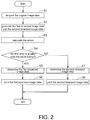
- FIG. 2 is a flowchart showing the flow of processes performed by the printing device 2 according to the first embodiment.
- FIG. 3 is a conceptual diagram showing an example of the flow of processes performed by the printing device 2 according to the first embodiment.
- each pixel array of the original image data and the binarized image data is set to a size of 8 ⁇ 8 (that is, the size has 8 pixels in a horizontal direction and 8 pixels in a vertical direction).
- the first halftone process the pixel value of the pixel included in the original image data is compared with the threshold value of the dither matrix having the size of 2 ⁇ 2 corresponding to the aforesaid pixel. Through the comparison, as shown in FIG.
- the calculation part 12 calculates an error between the generated first binarized image data and the original image data, and calculates an error between the generated second binarized image data and the original image data (S3).
- the error (mean square) between the first binarized image data and the original image data is "8911"
- the error (mean square) between the second binarized image data and the original image data is "9034.”
- the determination part 14 determines the binarized image data, in which the error calculated by the calculation part 12 is the smallest, among the first binarized image data and the second binarized image data. As shown in the example of FIG. 3 , if the error (first error) between the first binarized image data and the original image data is smaller than the error (second error) between the second binarized image data and the original image data (YES in S4), the determination part 14 determines the first binarized image data (S5). In this case, the printing part 16 prints the first binarized image data determined by the determination part 14 on the paper 4 (S6).
- the process flow returns to Step S4, and if the error obtained by executing the second halftone process is smaller than the error obtained by executing the first halftone process (NO in S4), the determination part 14 determines the second binarized image data (S7). In this case, the printing part 16 prints the second binarized image data determined by the determination part 14 on the paper 4 (S8).
- the determination part 14 determines the binarized image data, in which the error calculated by the calculation part 12 is the smallest, among the first binarized image data and the second binarized image data.
- the halftone process corresponding to the binarized image data determined in this manner is considered to be more compatible with the original image data. Therefore, by printing the binarized image data determined in this manner on the paper 4, the unevenness in the image quality of the binarized image data can be suppressed.
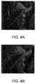
- FIG. 4A is a diagram showing an example of the first binarized image data obtained by executing the first halftone process on the original image data.
- FIG. 4B is a diagram showing an example of the second binarized image data obtained by executing the second halftone process on the original image data.
- the resolutions of the first binarized image data and the second binarized image data were both 1200dpi.
- the first halftone process was a halftone process performed by a dither method that used a dither matrix having a size of 2 ⁇ 2
- the second halftone process was a halftone process performed by a dither method that used a dither matrix having a size of 4 ⁇ 4.
- the error (mean square) between the first binarized image data and the original image data was "14021.225”
- the error (mean square) between the second binarized image data and the original image data was "13244.292.”
- the image quality of the second binarized image data having the smaller error is higher than the image quality of the first binarized image data.
- the unevenness in the image quality of the binarized image data can be suppressed by determining one of the first binarized image data and the second binarized image data according to the error calculated by the calculation part 12.
- FIG. 5 is a block diagram showing the functional configuration of the printing device 2A according to the second embodiment.
- FIG. 6 is a conceptual diagram showing an example of the flow of processes performed by the printing device 2A according to the second embodiment.
- components the same as those of the first embodiment are assigned with the same reference numerals and descriptions thereof are omitted.
- the printing device 2A of the second embodiment differs from the first embodiment in the configuration of a calculation part 12A. That is, when calculating the error, the calculation part 12A uses the pixel value "200" corresponding to the density of a background color of the paper 4 (e.g., white plain paper), instead of the pixel value "255" described in the first embodiment, as the pixel value of each white pixel of the first binarized image data and the second binarized image data.
- a background color of the paper 4 e.g., white plain paper
- the calculation part 12A uses the pixel value "15" corresponding to the density of the color of a black ink used by the printing part 16, instead of the pixel value "0" described in the first embodiment, as the pixel value of each black pixel of the first binarized image data and the second binarized image data.
- the pixel value "200" corresponding to the density of the background color of the paper 4 as described above is a density obtained in advance by measuring the density of the background color of the paper 4 with a colorimeter, and is a relative density when a black reference density of a color chart is set to "0" and a white reference density is set to "255.”
- the pixel value "15" corresponding to the density of the black ink as described above is a density obtained in advance by measuring the density of the dots formed on the paper 4 with the black ink with the colorimeter, and is a relative density when the black reference density of the color chart is set to "0" and the white reference density is set to "255.”
- the pixel values "200” and "15” are respectively stored in advance in a storage part 8A as pixel value data.
- the error (mean square) between the first binarized image data and the original image data is "5189” and the error (mean square) between the second binarized image data and the original image data is "4932.”
- the density of the background color of the paper 4 and the density of the color of the black ink are taken into consideration when the error is calculated by the calculation part 12A.
- the error can be calculated with high accuracy.
- the second embodiment illustrates a case where the printing device 2A is an inkjet printer. However, the same processing as described above can be executed even when the printing device 2A is a laser printer.
- the printing part 16 fixes a black toner (an example of the recording agent) onto the paper 4, so as to form a large number of dots on the paper 4.
- the calculation part 12A uses the pixel value (e.g., the pixel value "10") corresponding to the density of the color of the black toner used by the printing part 16, instead of the pixel value "0" described in the first embodiment, as the pixel value of each black pixel of the first binarized image data and the second binarized image data.
- FIG. 7 is a block diagram showing the functional configuration of the printing device 2B according to the third embodiment.
- the printing device 2B includes a division part 18 in addition to an acquisition part 6, a generation part 10B, a calculation part 12B, a determination part 14B, and a printing part 16B.
- the division part 18 divides the original image data acquired by the acquisition part 6 into a plurality of blocks (three, for example). As shown in FIG. 9 (which will be described later), the blocks are arranged side by side along a printing direction (sub-scanning direction) of the binarized image data of the printing part 16B.
- the generation part 10B executes the first halftone process and the second halftone process on the blocks, so as to generate the first binarized image data and the second binarized image data corresponding to each of the blocks.
- the calculation part 12B calculates the errors between the block and the first binarized image data and between the block and the second binarized image data.
- the determination part 14B determines the binarized image data, in which the calculated error is the smallest, among the first binarized image data and the second binarized image data for each block.
- the printing part 16B prints the determined binarized image data on the paper 4 for each block.
- FIG. 8 is a flowchart showing the flow of processes performed by the printing device 2B according to the third embodiment.
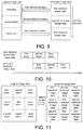
- FIG. 9 is a conceptual diagram showing an example of the flow of processes performed by the printing device 2B according to the third embodiment.
- the acquisition part 6 acquires the original image data that has been transmitted from the external terminal device, for example (S11). Then, the division part 18 divides the original image data acquired by the acquisition part 6 into a plurality of blocks (S12). In the example shown in FIG. 9 , the division part 18 divides the original image data into three blocks (a first block, a second block, and a third block). The three blocks are arranged side by side along a longitudinal direction (i.e., the printing direction of the binarized image data) of the original image data, for example.
- a longitudinal direction i.e., the printing direction of the binarized image data
- the generation part 10B executes the first halftone process and the second halftone process respectively on each pixel value of the pixels included in the first block, so as to generate the first binarized image data and the second binarized image data corresponding to the first block (S13).
- the calculation part 12B calculates the error between the generated first binarized image data and the first block, and calculates the error between the generated second binarized image data and the first block (S 14).
- the determination part 14B determines the binarized image data, in which the error calculated by the calculation part 12B is the smallest, among the first binarized image data and the second binarized image data for the first block. As shown in the example of FIG. 9 , if the error (first error) between the first binarized image data and the first block is smaller than the error (second error) between the second binarized image data and the first block (YES in S15), the determination part 14B determines the first binarized image data for the first block (S16). In this case, the printing part 16B prints the first binarized image data, as the binarized image data corresponding to the first block, on the paper 4 (S17).
- the process flow returns to Step S15, and if the error between the second binarized image data and the first block is smaller than the error between the first binarized image data and the first block (NO in S15), the determination part 14B determines the second binarized image data for the first block (S18). In this case, the printing part 16B prints the second binarized image data, as the binarized image data corresponding to the first block, on the paper 4 (S19).
- the aforementioned Steps S13 to S19 are executed for the second block.
- the determination part 14B determines the second binarized image data for the second block, and the printing part 16B prints the second binarized image data, as the binarized image data corresponding to the second block, on the paper 4.
- the determination part 14B determines the first binarized image data for the third block, and the printing part 16B prints the first binarized image data, as the binarized image data corresponding to the third block, on the paper 4.
- the error is calculated for each block. Therefore, it is possible to determine the binarized image data corresponding to the halftone process that is most compatible with the original image data for each block. For example, if the original image data includes both a character area and a photograph area, dividing the original image data into a block including the character area and a block including the photograph area makes it possible to appropriately determine the binarized image data that is respectively compatible with the block including the character area and the block including the photograph area. As a result, the unevenness in the image quality of the binarized image data printed on the paper 4 can be effectively suppressed.
- the configuration is made such that determination of the binarized image data for the second block is started after printing of the binarized image data for the first block is completed.
- determination of the binarized image data for the second block may be started simultaneously when printing of the binarized image data for the first block is started at a timing when determination of the binarized image data for the first block has been completed. Thereby, the time required for the printing device 2B to carry out the processes can be shortened.
- the division part 18 divides the original image data into three blocks in the third embodiment, the number of the blocks that are divided can be set as desired. In the example shown in FIG. 11 , the division part 18 divides the original image data into a total of nine blocks (first block to ninth block). In this way, as the number of the blocks that are divided increases, the unevenness in the image quality of the binarized image data printed on the paper 4 can be more effectively suppressed.
- the printing device 2 (2A, 2B) is constituted by an inkjet printer.
- the invention is not limited thereto, and the printing device 2 (2A, 2B) may also be constituted by a laser printer or a multifunction peripheral (MFP), for example.
- MFP multifunction peripheral
- the acquisition part 6 acquires the original image data read by a scanner.
- the generation part 10 (10B) executes two types of halftone processes on the original image data.
- the invention is not limited thereto, and the generation part 10 (10B) may execute three or more types of halftone processes, for example.
- the generation part 10 (10B) is configured to execute the halftone process by the dither method using multiple types of dither matrices that have different sizes and threshold values.
- the invention is not limited thereto, and the generation part 10 (10B) may execute the halftone process by the dither method using multiple types of dither matrices that have the same sizes but are different only in threshold values, for example.
- the halftone process by the dither method is used as the halftone process to be executed by the generation part 10 (10B).
- the invention is not limited thereto, and a halftone process by an error diffusion method may be used, for example.
- a combination of the halftone process by the dither method and the halftone process by the error diffusion method can be used.
- the halftone process may be executed with using one of threshold values of multiple types.
- a first threshold value e.g., "128”
- a second threshold value e.g., "135"
- the pixel value of the original image data is larger than the first threshold value, the pixel value is converted to "255,” and if the pixel value of the original image data is smaller than the first threshold value, the pixel value is converted to "0.”
- the pixel value of the original image data is larger than the second threshold value, the pixel value is converted to "255,” and if the pixel value of the original image data is smaller than the second threshold value, the pixel value is converted to "0.”
- the error is calculated for the entire original image data.
- the invention is not limited thereto, and the error may be calculated for only a part of the original image data.
- the printing device of the invention is applicable to serve as an inkjet printer, a laser printer, or the like, for example.
Landscapes
- Engineering & Computer Science (AREA)
- Multimedia (AREA)
- Signal Processing (AREA)
- Health & Medical Sciences (AREA)
- Biomedical Technology (AREA)
- General Health & Medical Sciences (AREA)
- Facsimile Image Signal Circuits (AREA)
- Color, Gradation (AREA)
- Image Processing (AREA)
- Ink Jet (AREA)
- Particle Formation And Scattering Control In Inkjet Printers (AREA)
- Computer Vision & Pattern Recognition (AREA)
- Physics & Mathematics (AREA)
- General Physics & Mathematics (AREA)
- Theoretical Computer Science (AREA)
Abstract
Description
- The invention relates to an image forming device for forming binarized image data.
- Inkjet printers, laser printers, etc., for example, are known as image forming devices or printing devices that print binarized image data by forming a large number of dots on paper. Such printing devices change the number of dots formed in a certain area on the paper, so as to represent a pseudo-intermediate gradation of the binarized image data (refer to Patent Literature 1: Japanese Patent Publication No.
2007-67984 - With respect to the conventional printing devices, the binarized image data, including black pixels that form the dots and white pixels that do not form the dots, is generated by executing a halftone process on each pixel value of multiple pixels included in multi-gradation original image data. The aforementioned halftone process has several types, such as halftone process by a dither method, halftone process by an error diffusion method, and so on.
- In terms of the aforementioned conventional printing devices, since the halftone process is fixed to one type in advance, the image quality of the binarized image data may vary due to compatibility between the original image data and the type of the halftone process.
- In view of the above, the invention provides a printing device that is capable of suppressing the unevenness in the image quality of the binarized image data.
- In view of the aforementioned, according to one embodiment, the disclosure provides a printing device, including a generation part, a determination part and a printing part. The generation part generates a plurality of types of binarized image data with respect to original image data. The determination part determines the binarized image data, in which an error between each of the plurality of the types of the binarized image data and the original image data is smaller, among the plurality of the types of the binarized image data. The printing part prints the binarized image data determined by the determination part on a medium.
- According to one embodiment, in the aforementioned image forming device, the image forming device comprises a division part dividing the original image data into a plurality of blocks. Further, according to one embodiment, in the aforementioned image forming device, the generation part generates the plurality of the types of the binarized image data by executing a plurality of types of processes on each of the blocks.
- According to one embodiment, in the aforementioned image forming devices, the image forming device respectively calculates an error between each of the plurality of the types of the binarized image data and the blocks for each of the blocks. In addition, the determination part determines the binarized image data, in which the error that is calculated is smaller, among the plurality of the types of the binarized image data for each of the blocks.
- According to one embodiment, in the aforementioned image forming devices, the printing part prints the binarized image data that is determined on the medium for each of the blocks.
- According to one embodiment, in the aforementioned image forming devices, the blocks are arranged side by side along a predetermined direction of the binarized image data by the printing part. In addition, according to one embodiment, in the aforementioned image forming devices, the predetermined direction can be a printing direction of the binarized image data.
- According to one embodiment, in the aforementioned image forming devices, image forming device comprises a calculation part, respectively calculating the error between each of the plurality of the types of the binarized image data and the original image data.
- According to one embodiment, in the aforementioned image forming devices, each of the plurality of the types of the binarized image data comprises a plurality of first pixels and a plurality of second pixels.
- According to one embodiment, in the aforementioned image forming devices, the calculation part calculates an error between a pixel value of a pixel included in the original image data and a pixel value of the first pixel or a pixel value of the second pixel of the binarized image data corresponding to the pixel included in the original image data.
- According to one embodiment, in the aforementioned image forming devices, the calculation part uses a pixel value that corresponds to a density of a background color of the medium as the pixel value of the first pixel when calculating the error.
- According to one embodiment, in the aforementioned image forming devices, the image forming device prints the binarized image data on the medium with a recording agent. Further, according to one embodiment, in the aforementioned image forming devices, the calculation part uses a pixel value that corresponds to a density of a color of the recording agent as the pixel value of the second pixel when calculating the error. In one embodiment, the recording agent can be an ink or a toner.
- According to one embodiment, in the aforementioned image forming devices, the plurality of the types of the processes comprise an error diffusion method and/or a dither method. Alternatively, in one embodiment, the plurality of the types of the processes are a dither method using a plurality of types of dither matrices. Further, the plurality of the types of the dither matrices have different sizes or different threshold values.
- According to one embodiment, in the aforementioned image forming devices, the image forming device comprises an acquisition part acquiring the original image data. In addition, in the aforementioned embodiments, the first pixel and the second pixel are a white pixel and a black pixel respectively.
- According to this embodiment, the determination part preferentially determines the binarized image data, in which the error calculated by the calculation part is smaller, among the multiple types of the binarized image data. Among the multiple types of halftone processes, the halftone process corresponding to the binarized image data as determined is considered to be more compatible with the original image data. Therefore, by printing the binarized image data as determined on the paper, the unevenness in the image quality of the binarized image data can be suppressed.
- According to above embodiments, the division part divides the original image data into a plurality of blocks, and the generation part generates multiple types of the binarized image data for each block. Accordingly, the calculation part calculates the error for each block. Therefore, it is possible to determine the binarized image data corresponding to the halftone process that is more compatible with the original image data for each block. As a result, the unevenness in the image quality of the binarized image data can be more effectively suppressed.
- According to above embodiments, the blocks can be arranged side by side along the printing direction of the binarized image data of the printing part. Therefore, for example, after the binarized image data for a certain block is determined, the determination of the binarized image data for a block adjacent to the certain block can be started simultaneously when printing of the binarized image data for the certain block is started. Thereby, the time required for the printing device to carry out the processes can be shortened.
- According to above embodiments, when calculating the error, the calculation part uses the pixel value corresponding to the density of the background color of the paper as the pixel value of the white pixel of the binarized image data. Thereby, the density of the background color of the paper is taken into consideration when the error is calculated by the calculation part. Thus, the error can be calculated with high accuracy.
- According to above embodiments, when calculating the error, the calculation part uses the pixel value corresponding to the density of the color of the black ink (an example of the recording agent) as the pixel value of the black pixel of the binarized image data. Thereby, the density of the color of the black ink is taken into consideration when the error is calculated by the calculation part. Thus, the error can be calculated with high accuracy.
- According to above embodiments, when calculating the error, the calculation part uses the pixel value corresponding to the density of the color of the black toner (an example of the recording agent) as the pixel value of the black pixel of the binarized image data. Thereby, the density of the color of the black toner is taken into consideration when the error is calculated by the calculation part. Thus, the error can be calculated with high accuracy.
- According to the above embodiments, at least one of the halftone process performed by the dither method and the halftone process performed by the error diffusion method can be used as the multiple types of halftone processes.
- According to the above embodiments, the halftone process performed by the dither method using multiple types of dither matrices that have different sizes and/or threshold values can be used as the multiple types of halftone processes.
- According to the printing device of an embodiment of the disclosure, the unevenness in the image quality of the binarized image data can be suppressed.
-
-
FIG. 1 is a block diagram showing the functional configuration of the printing device according to the first embodiment. -
FIG. 2 is a flowchart showing the flow of processes performed by the printing device according to the first embodiment. -
FIG. 3 is a conceptual diagram showing an example of the flow of processes performed by the printing device according to the first embodiment. -
FIG. 4A is a diagram showing an example of the first binarized image data obtained by executing the first halftone process on the original image data. -
FIG. 4B is a diagram showing an example of the second binarized image data obtained by executing the second halftone process on the original image data. -
FIG. 5 is a block diagram showing the functional configuration of the printing device according to the second embodiment. -
FIG. 6 is a conceptual diagram showing an example of the flow of processes performed by the printing device according to the second embodiment. -
FIG. 7 is a block diagram showing the functional configuration of the printing device according to the third embodiment. -
FIG. 8 is a flowchart showing the flow of processes performed by the printing device according to the third embodiment. -
FIG. 9 is a conceptual diagram showing an example of the flow of processes performed by the printing device according to the third embodiment. -
FIG. 10 is a timing chart showing an example of the flow of processes performed by the printing device according to a modified example of the third embodiment. -
FIG. 11 is a conceptual diagram showing an example of the flow of processes performed by the printing device according to the modified example of the third embodiment. - Hereinafter, embodiments of the invention are described in detail with reference to the figures. The embodiments described below are all inclusive or specific examples. The values, shapes, materials, components, arrangement positions and connection forms of the components, steps and order of the steps, and so on in the following embodiments are merely examples and are not intended to limit the invention. Moreover, among the components in the following embodiments, those that are not recited in the independent claims are described as optional components. The figures are not necessarily drawn to precisely show the dimensions or dimensional ratios.
- First, a functional configuration of An
image forming device 2 of the first embodiment is described with reference toFIG. 1 . In this and following embodiments, a printing device will be used to explain the embodiment as an example for the image forming device.FIG. 1 is a block diagram showing the functional configuration of theprinting device 2 according to the first embodiment. - The
printing device 2 of the first embodiment is, for example, an inkjet printer for printing binarized image data by forming a large number of dots on paper (an example of medium) 4. As shown inFIG. 1 , theprinting device 2 includes anacquisition part 6, astorage part 8, ageneration part 10, acalculation part 12, adetermination part 14, and aprinting part 16. Theprinting device 2 is connected to an external terminal device (e.g., a personal computer) (not shown) in a communicable manner. Besides, thepaper 4 is a piece of white plain paper or the like, for example. - The
acquisition part 6 acquires original image data that has been transmitted from the external terminal device, for example. The original image data is multi-gradation grayscale image data that has an 8-bit gradation value, for example, and includes a plurality of pixels arranged in a matrix. That is, each of the pixels included in the original image data has a pixel value of "0" to "255." - The
storage part 8 is a memory for storing two types of dither matrices that have different sizes and threshold values (e.g., a dither matrix having a size of 2×2 and a dither matrix having a size of 4×4) (so-called dot pattern), for example. Details of the dither matrices will be described later. - The
generation part 10 executes two types of halftone processes (a first halftone process and a second halftone process) on each pixel value of the pixels included in the entire original image data, so as to generate two types of binarized image data (first binarized image data and second binarized image data) corresponding to the entire original image data. Each of the two types of halftone processes is a halftone process performed by a dither method that uses the two types of dither matrices stored in thestorage part 8. The binarized image data is halftone image data that has a gradation value of one bit, and includes a plurality of pixels arranged in a matrix. That is, each of the pixels included in the binarized image data has a pixel value of "0" or "255" (binary). Here, the pixel having the pixel value of "255" is a white pixel that does not form a dot, and the pixel having the pixel value of "0" is a black pixel that forms a dot. The binarized image data has the same resolution as the original image data, for example. - The
calculation part 12 calculates errors respectively between the two types of binarized image data and the original image data. That is, thecalculation part 12 calculates the error (e.g., mean square) between the pixel value of the pixel (white pixel or black pixel) included in the binarized image data and the pixel value of the pixel of the original image data corresponding to the aforesaid pixel, respectively for the two types of binarized image data. In the case of calculating a mean square as the error, for example, when the total number of the pixels included in each of the original image data and the binarized image data is N, the pixel value of the pixel included in the binarized image data is Pi (i = 1, 2, ..., N), and the pixel value of the pixel of the original image data corresponding to the pixel of the aforesaid binarized image data is Pi' (i=1, 2, ..., N), the error Av is calculated according to the following Equation (1).
- The
determination part 14 preferentially determines (or selects) the binarized image data, in which the error calculated by thecalculation part 12 is smaller, among the aforementioned two types of binarized image data. That is, thedetermination part 14 determines the binarized image data, in which the error calculated by thecalculation part 12 is the smallest, among the aforementioned two types of binarized image data. - The
printing part 16 prints the binarized image data determined by thedetermination part 14 on thepaper 4. Theprinting part 16 discharges black ink (an example of a recording agent) from a recording head (not shown) to thepaper 4 at an appropriate timing while reciprocally moving the recording head in a direction substantially perpendicular to a conveyance direction of thepaper 4, so as to form a large number of dots on thepaper 4. By forming a large number of dots on thepaper 4 in this way, the binarized image data is printed on thepaper 4. - Next, a flow of processes performed by the
printing device 2 is described with reference toFIG. 2 andFIG. 3 .FIG. 2 is a flowchart showing the flow of processes performed by theprinting device 2 according to the first embodiment.FIG. 3 is a conceptual diagram showing an example of the flow of processes performed by theprinting device 2 according to the first embodiment. To make the following easily comprehensible, in the example shown inFIG. 3 , each pixel array of the original image data and the binarized image data is set to a size of 8×8 (that is, the size has 8 pixels in a horizontal direction and 8 pixels in a vertical direction). - As shown in
FIG. 2 , first, theacquisition part 6 acquires the original image data that has been transmitted from the external terminal device, for example (S1). Then, as shown inFIG. 3 , thegeneration part 10 executes the first halftone process and the second halftone process respectively on each pixel value of the pixels included in the entire original image data, so as to generate the first binarized image data and the second binarized image data (S2). In the example shown inFIG. 3 , the first halftone process is a halftone process performed by a dither method that uses a dither matrix having a size of 2×2, and the second halftone process is a halftone process performed by a dither method that uses a dither matrix having a size of 4×4. As shown inFIG. 3 , the dither matrix having the size of 2×2 and the dither matrix having the size of 4×4 have different sizes and threshold values. - A brief explanation of the first halftone process and the second halftone process is provided. In the first halftone process, the pixel value of the pixel included in the original image data is compared with the threshold value of the dither matrix having the size of 2×2 corresponding to the aforesaid pixel. Through the comparison, as shown in
FIG. 3 , if the pixel value of the original image data is larger than the corresponding threshold value of the dither matrix having the size of 2×2, the pixel value is converted to "255," and if the pixel value of the original image data is smaller than the corresponding threshold value of the dither matrix having the size of 2×2, the pixel value is converted to "0." That is, by the first halftone process, the pixel value of the pixel included in the original image data is binarized to either "255" or "0." For example, the pixel values "173," "161," "67," and "75" of the four pixels that occupy the pixel array having the size of 2×2 on the upper left of the original image data shown inFIG. 3 are respectively compared with the threshold values "32," "160," "96," and "224" of the dither matrix having the size of 2×2. As a result, the pixel values "173," "161," "67," and "75" of the original image data are converted to pixel values "255," "255," "0," and "0" respectively. - On the other hand, in the second halftone process, the pixel value of the pixel included in the original image data is compared with the threshold value of the dither matrix having the size of 4×4 corresponding to the aforesaid pixel in the same manner as the first halftone process described above. Through the comparison, as shown in
FIG. 3 , if the pixel value of the original image data is larger than the corresponding threshold value of the dither matrix having the size of 4×4, the pixel value is converted to "255," and if the pixel value of the original image data is smaller than the corresponding threshold value of the dither matrix having the size of 4×4, the pixel value is converted to "0." - Thereafter, the
calculation part 12 calculates an error between the generated first binarized image data and the original image data, and calculates an error between the generated second binarized image data and the original image data (S3). In the example shown inFIG. 3 , the error (mean square) between the first binarized image data and the original image data is "8911" and the error (mean square) between the second binarized image data and the original image data is "9034." - Then, the
determination part 14 determines the binarized image data, in which the error calculated by thecalculation part 12 is the smallest, among the first binarized image data and the second binarized image data. As shown in the example ofFIG. 3 , if the error (first error) between the first binarized image data and the original image data is smaller than the error (second error) between the second binarized image data and the original image data (YES in S4), thedetermination part 14 determines the first binarized image data (S5). In this case, theprinting part 16 prints the first binarized image data determined by thedetermination part 14 on the paper 4 (S6). - The process flow returns to Step S4, and if the error obtained by executing the second halftone process is smaller than the error obtained by executing the first halftone process (NO in S4), the
determination part 14 determines the second binarized image data (S7). In this case, theprinting part 16 prints the second binarized image data determined by thedetermination part 14 on the paper 4 (S8). - The effect achieved by the
printing device 2 of the first embodiment will be described hereinafter. As described above, thedetermination part 14 determines the binarized image data, in which the error calculated by thecalculation part 12 is the smallest, among the first binarized image data and the second binarized image data. The halftone process corresponding to the binarized image data determined in this manner is considered to be more compatible with the original image data. Therefore, by printing the binarized image data determined in this manner on thepaper 4, the unevenness in the image quality of the binarized image data can be suppressed. - Here, in order to confirm the aforementioned effect, comparison was performed on the image quality of the first binarized image data and the second binarized image data obtained by respectively executing the first halftone process and the second halftone process on the original image data (so-called Lenna image).
FIG. 4A is a diagram showing an example of the first binarized image data obtained by executing the first halftone process on the original image data.FIG. 4B is a diagram showing an example of the second binarized image data obtained by executing the second halftone process on the original image data. - In the examples shown in
FIG. 4A and FIG. 4B , the resolutions of the first binarized image data and the second binarized image data were both 1200dpi. Moreover, the first halftone process was a halftone process performed by a dither method that used a dither matrix having a size of 2×2, and the second halftone process was a halftone process performed by a dither method that used a dither matrix having a size of 4×4. Furthermore, the error (mean square) between the first binarized image data and the original image data was "14021.225," and the error (mean square) between the second binarized image data and the original image data was "13244.292." - As clearly shown in
FIG. 4A and FIG. 4B , it can be said that the image quality of the second binarized image data having the smaller error is higher than the image quality of the first binarized image data. Thus, it was confirmed that the unevenness in the image quality of the binarized image data can be suppressed by determining one of the first binarized image data and the second binarized image data according to the error calculated by thecalculation part 12. - Next, a functional configuration of a
printing device 2A of the second embodiment is described with reference toFIG. 5 andFIG. 6 .FIG. 5 is a block diagram showing the functional configuration of theprinting device 2A according to the second embodiment.FIG. 6 is a conceptual diagram showing an example of the flow of processes performed by theprinting device 2A according to the second embodiment. In the following embodiments, components the same as those of the first embodiment are assigned with the same reference numerals and descriptions thereof are omitted. - As shown in
FIG. 5 , theprinting device 2A of the second embodiment differs from the first embodiment in the configuration of acalculation part 12A. That is, when calculating the error, thecalculation part 12A uses the pixel value "200" corresponding to the density of a background color of the paper 4 (e.g., white plain paper), instead of the pixel value "255" described in the first embodiment, as the pixel value of each white pixel of the first binarized image data and the second binarized image data. Moreover, when calculating the error, thecalculation part 12A uses the pixel value "15" corresponding to the density of the color of a black ink used by theprinting part 16, instead of the pixel value "0" described in the first embodiment, as the pixel value of each black pixel of the first binarized image data and the second binarized image data. - The pixel value "200" corresponding to the density of the background color of the
paper 4 as described above is a density obtained in advance by measuring the density of the background color of thepaper 4 with a colorimeter, and is a relative density when a black reference density of a color chart is set to "0" and a white reference density is set to "255." In addition, the pixel value "15" corresponding to the density of the black ink as described above is a density obtained in advance by measuring the density of the dots formed on thepaper 4 with the black ink with the colorimeter, and is a relative density when the black reference density of the color chart is set to "0" and the white reference density is set to "255." The pixel values "200" and "15" are respectively stored in advance in astorage part 8A as pixel value data. - In the example shown in
FIG. 6 , the error (mean square) between the first binarized image data and the original image data is "5189" and the error (mean square) between the second binarized image data and the original image data is "4932." - Accordingly, in the second embodiment, the density of the background color of the
paper 4 and the density of the color of the black ink are taken into consideration when the error is calculated by thecalculation part 12A. Thus, the error can be calculated with high accuracy. - The second embodiment illustrates a case where the
printing device 2A is an inkjet printer. However, the same processing as described above can be executed even when theprinting device 2A is a laser printer. - In the case where the
printing device 2A is a laser printer, theprinting part 16 fixes a black toner (an example of the recording agent) onto thepaper 4, so as to form a large number of dots on thepaper 4. In this case, when calculating the error, thecalculation part 12A uses the pixel value (e.g., the pixel value "10") corresponding to the density of the color of the black toner used by theprinting part 16, instead of the pixel value "0" described in the first embodiment, as the pixel value of each black pixel of the first binarized image data and the second binarized image data. - Next, a functional configuration of a
printing device 2B of the third embodiment is described with reference toFIG. 7. FIG. 7 is a block diagram showing the functional configuration of theprinting device 2B according to the third embodiment. - As shown in
FIG. 7 , theprinting device 2B according to the third embodiment includes adivision part 18 in addition to anacquisition part 6, ageneration part 10B, acalculation part 12B, adetermination part 14B, and aprinting part 16B. Thedivision part 18 divides the original image data acquired by theacquisition part 6 into a plurality of blocks (three, for example). As shown inFIG. 9 (which will be described later), the blocks are arranged side by side along a printing direction (sub-scanning direction) of the binarized image data of theprinting part 16B. - The
generation part 10B executes the first halftone process and the second halftone process on the blocks, so as to generate the first binarized image data and the second binarized image data corresponding to each of the blocks. For each block, thecalculation part 12B calculates the errors between the block and the first binarized image data and between the block and the second binarized image data. - The
determination part 14B determines the binarized image data, in which the calculated error is the smallest, among the first binarized image data and the second binarized image data for each block. Theprinting part 16B prints the determined binarized image data on thepaper 4 for each block. - Next, a flow of processes performed by the
printing device 2B of the third embodiment is described with reference toFIG. 8 andFIG. 9 .FIG. 8 is a flowchart showing the flow of processes performed by theprinting device 2B according to the third embodiment.FIG. 9 is a conceptual diagram showing an example of the flow of processes performed by theprinting device 2B according to the third embodiment. - As shown in
FIG. 8 , first, theacquisition part 6 acquires the original image data that has been transmitted from the external terminal device, for example (S11). Then, thedivision part 18 divides the original image data acquired by theacquisition part 6 into a plurality of blocks (S12). In the example shown inFIG. 9 , thedivision part 18 divides the original image data into three blocks (a first block, a second block, and a third block). The three blocks are arranged side by side along a longitudinal direction (i.e., the printing direction of the binarized image data) of the original image data, for example. - Thereafter, the
generation part 10B executes the first halftone process and the second halftone process respectively on each pixel value of the pixels included in the first block, so as to generate the first binarized image data and the second binarized image data corresponding to the first block (S13). Thereafter, thecalculation part 12B calculates the error between the generated first binarized image data and the first block, and calculates the error between the generated second binarized image data and the first block (S 14). - Thereafter, the
determination part 14B determines the binarized image data, in which the error calculated by thecalculation part 12B is the smallest, among the first binarized image data and the second binarized image data for the first block. As shown in the example ofFIG. 9 , if the error (first error) between the first binarized image data and the first block is smaller than the error (second error) between the second binarized image data and the first block (YES in S15), thedetermination part 14B determines the first binarized image data for the first block (S16). In this case, theprinting part 16B prints the first binarized image data, as the binarized image data corresponding to the first block, on the paper 4 (S17). - The process flow returns to Step S15, and if the error between the second binarized image data and the first block is smaller than the error between the first binarized image data and the first block (NO in S15), the
determination part 14B determines the second binarized image data for the first block (S18). In this case, theprinting part 16B prints the second binarized image data, as the binarized image data corresponding to the first block, on the paper 4 (S19). - Next, if the binarized image data (i.e., one of the first binarized image data and the second binarized image data) for the remaining second block and third block is not printed on the paper 4 (NO in S20), the aforementioned Steps S13 to S19 are executed for the second block. In the example shown in
FIG. 9 , thedetermination part 14B determines the second binarized image data for the second block, and theprinting part 16B prints the second binarized image data, as the binarized image data corresponding to the second block, on thepaper 4. - Thereafter, if the binarized image data for the remaining third block is not printed on the paper 4 (NO in S20), the aforementioned Steps S13 to S19 are executed for the third block. In the example shown in
FIG. 9 , thedetermination part 14B determines the first binarized image data for the third block, and theprinting part 16B prints the first binarized image data, as the binarized image data corresponding to the third block, on thepaper 4. - Accordingly, with the
printing device 2B according to the third embodiment, the error is calculated for each block. Therefore, it is possible to determine the binarized image data corresponding to the halftone process that is most compatible with the original image data for each block. For example, if the original image data includes both a character area and a photograph area, dividing the original image data into a block including the character area and a block including the photograph area makes it possible to appropriately determine the binarized image data that is respectively compatible with the block including the character area and the block including the photograph area. As a result, the unevenness in the image quality of the binarized image data printed on thepaper 4 can be effectively suppressed. - In the third embodiment, for example, the configuration is made such that determination of the binarized image data for the second block is started after printing of the binarized image data for the first block is completed.
- Instead of this configuration, as shown in
FIG. 10 , for example, determination of the binarized image data for the second block may be started simultaneously when printing of the binarized image data for the first block is started at a timing when determination of the binarized image data for the first block has been completed. Thereby, the time required for theprinting device 2B to carry out the processes can be shortened. - Moreover, although the
division part 18 divides the original image data into three blocks in the third embodiment, the number of the blocks that are divided can be set as desired. In the example shown inFIG. 11 , thedivision part 18 divides the original image data into a total of nine blocks (first block to ninth block). In this way, as the number of the blocks that are divided increases, the unevenness in the image quality of the binarized image data printed on thepaper 4 can be more effectively suppressed. - The printing devices according to the first to third embodiments of the invention have been described above. Nevertheless, the invention is not limited to the first to third embodiments. For example, the first to third embodiments described above may be combined where appropriate.
- For example, in the above embodiments, the printing device 2 (2A, 2B) is constituted by an inkjet printer. However, the invention is not limited thereto, and the printing device 2 (2A, 2B) may also be constituted by a laser printer or a multifunction peripheral (MFP), for example. In the case where the printing device 2 (2A, 2B) is constituted by a multifunction peripheral, the
acquisition part 6 acquires the original image data read by a scanner. - For example, in the above embodiments, the generation part 10 (10B) executes two types of halftone processes on the original image data. However, the invention is not limited thereto, and the generation part 10 (10B) may execute three or more types of halftone processes, for example.
- For example, in the above embodiments, the generation part 10 (10B) is configured to execute the halftone process by the dither method using multiple types of dither matrices that have different sizes and threshold values. However, the invention is not limited thereto, and the generation part 10 (10B) may execute the halftone process by the dither method using multiple types of dither matrices that have the same sizes but are different only in threshold values, for example.
- For example, in the above embodiments, the halftone process by the dither method is used as the halftone process to be executed by the generation part 10 (10B). However, the invention is not limited thereto, and a halftone process by an error diffusion method may be used, for example. Alternatively, a combination of the halftone process by the dither method and the halftone process by the error diffusion method can be used.
- Alternatively, the halftone process may be executed with using one of threshold values of multiple types. In this case, for example, a first threshold value (e.g., "128") is used in the first halftone process and a second threshold value (e.g., "135") is used in the second halftone process. For example, in the first halftone process, if the pixel value of the original image data is larger than the first threshold value, the pixel value is converted to "255," and if the pixel value of the original image data is smaller than the first threshold value, the pixel value is converted to "0." Likewise, in the second halftone process, if the pixel value of the original image data is larger than the second threshold value, the pixel value is converted to "255," and if the pixel value of the original image data is smaller than the second threshold value, the pixel value is converted to "0."
- For example, in the first embodiment described above, the error is calculated for the entire original image data. However, the invention is not limited thereto, and the error may be calculated for only a part of the original image data.
- The printing device of the invention is applicable to serve as an inkjet printer, a laser printer, or the like, for example.
-
- 2, 2A, 2B
- printing device
- 4
- medium
- 6
- acquisition part
- 8, 8A
- storage part
- 10, 10B
- generation part
- 12, 12A, 12B
- calculation part
- 14, 14B
- determination part
- 16, 16B
- printing part
- 18
- division part
Claims (15)
- An image forming device (2A), characterized in that the image forming device (2A) comprises:a generation part (10), configured to generate a plurality of types of binarized image data with respect to original image data;a determination part (14), configured to determine the binarized image data, in which an error between each of the plurality of the types of the binarized image data and the original image data is smaller, among the plurality of the types of the binarized image data; anda printing part (16), configured to print the binarized image data determined by the determination part (14) on a medium (4).
- The image forming device (2A) according to claim 1, characterized in that the image forming device (2A) comprises a division part (18) configured to divide the original image data into a plurality of blocks.
- The image forming device (2A) according to claim 2, characterized in that the generation part (10) is configured to generate the plurality of the types of the binarized image data by executing a plurality of types of processes on each of the blocks.
- The image forming device (2A) according to any one of claims 2-3, characterized in that the image forming device (2A) is configured to respectively calculate an error between each of the plurality of the types of the binarized image data and the blocks for each of the blocks,
wherein the determination part (14) is configured to determine the binarized image data, in which the error that is calculated is smaller, among the plurality of the types of the binarized image data for each of the blocks. - The image forming device (2A) according to any one of claims 2-4, characterized in that the printing part (16) is configured to print the binarized image data that is determined on the medium (4) for each of the blocks.
- The image forming device (2A) according to any one of claims 2-5, characterized in that the blocks are arranged side by side along a predetermined direction of the binarized image data by the printing part (16).
- The image forming device (2A) according to any one of claims 1-6, characterized in that the image forming device (2A) comprises a calculation part (12) respectively calculating the error between each of the plurality of the types of the binarized image data and the original image data.
- The image forming device (2A) according to any one of claims 1-7, characterized in that each of the plurality of the types of the binarized image data comprises a plurality of first pixels and a plurality of second pixels.
- The image forming device (2A) according to claim 8, characterized in that the calculation part (12A) is configured to calculate an error between a pixel value of a pixel included in the original image data and a pixel value of the first pixel or a pixel value of the second pixel of the binarized image data corresponding to the pixel included in the original image data.
- The image forming device (2A) according to claim 8 or 9, characterized in that the calculation part (12A) is configured to use a pixel value that corresponds to a density of a background color of the medium (4) as the pixel value of the first pixel when calculating the error.
- The image forming device (2A) according to any one of claims 1-10, characterized in that the image forming device (2A) is configured to print the binarized image data on the medium (4) with a recording agent.
- The image forming device (2A) according to claim 11, characterized in that the calculation part (12A) is configured to use a pixel value that corresponds to a density of a color of the recording agent as the pixel value of the second pixel when calculating the error.
- The image forming device (2A) according to any one of claims 3-12, characterized in that the plurality of the types of the processes comprise an error diffusion method and/or a dither method.
- The image forming device (2A) according to any one of claims 3-12, characterized in that the plurality of the types of the processes are a dither method using a plurality of types of dither matrices.
- The image forming device (2A) according to claim 14, characterized in that the plurality of the types of the dither matrices have different sizes or different threshold values.
Applications Claiming Priority (1)
| Application Number | Priority Date | Filing Date | Title |
|---|---|---|---|
| JP2016073229A JP2017184197A (en) | 2016-03-31 | 2016-03-31 | Printer |
Publications (1)
| Publication Number | Publication Date |
|---|---|
| EP3226531A1 true EP3226531A1 (en) | 2017-10-04 |
Family
ID=58461080
Family Applications (1)
| Application Number | Title | Priority Date | Filing Date |
|---|---|---|---|
| EP17163312.6A Withdrawn EP3226531A1 (en) | 2016-03-31 | 2017-03-28 | Image forming device with halftoning selection process |
Country Status (4)
| Country | Link |
|---|---|
| US (1) | US10257386B2 (en) |
| EP (1) | EP3226531A1 (en) |
| JP (1) | JP2017184197A (en) |
| CN (1) | CN107277291B (en) |
Cited By (1)
| Publication number | Priority date | Publication date | Assignee | Title |
|---|---|---|---|---|
| US11909939B2 (en) | 2018-11-27 | 2024-02-20 | Toppan Printing Co., Ltd. | Method of generating image data, method of producing display, program, computer-readable storage medium, and display production system |
Families Citing this family (1)
| Publication number | Priority date | Publication date | Assignee | Title |
|---|---|---|---|---|
| JP7050599B2 (en) * | 2018-07-06 | 2022-04-08 | シャープ株式会社 | Image processing device and image processing method |
Citations (7)
| Publication number | Priority date | Publication date | Assignee | Title |
|---|---|---|---|---|
| JPS62269471A (en) * | 1986-05-16 | 1987-11-21 | Matsushita Graphic Commun Syst Inc | Evaluating device for image binarization processing |
| US20020054354A1 (en) * | 2000-09-20 | 2002-05-09 | Suzuko Fukao | Image processing apparatus and image processing method |
| US20050008245A1 (en) * | 2003-07-11 | 2005-01-13 | Terumitsu Katougi | Image processing method, image processor, image forming apparatus and memory product |
| US20060197989A1 (en) * | 2005-03-07 | 2006-09-07 | Toshiba Corporation | Multi-configured halftone system |
| JP2007067984A (en) | 2005-09-01 | 2007-03-15 | Dainippon Printing Co Ltd | Density correction method and density correction apparatus for binary image |
| US20120188610A1 (en) * | 2011-01-26 | 2012-07-26 | Canon Kabushiki Kaisha | Image processing apparatus and image processing method |
| EP3125521A1 (en) * | 2014-03-27 | 2017-02-01 | Fujifilm Corporation | Printing system, halftone processing rule generation method, characteristic parameter acquisition method, image processing device and method, halftone processing rule, halftone image, printed matter production method, inkjet printing system, and program |
Family Cites Families (22)
| Publication number | Priority date | Publication date | Assignee | Title |
|---|---|---|---|---|
| JPS61285867A (en) * | 1985-06-12 | 1986-12-16 | Dainippon Screen Mfg Co Ltd | Recording method and device for dot picture |
| JP2621865B2 (en) * | 1987-05-21 | 1997-06-18 | キヤノン株式会社 | Image processing device |
| JP3077873B2 (en) * | 1994-06-07 | 2000-08-21 | 大日本スクリーン製造株式会社 | Method and apparatus for creating printing plate image |
| US5745660A (en) * | 1995-04-26 | 1998-04-28 | Polaroid Corporation | Image rendering system and method for generating stochastic threshold arrays for use therewith |
| US6100996A (en) * | 1996-03-08 | 2000-08-08 | Canon Kabushiki Kaisha | Image processing apparatus and method, print control apparatus and method, and printer |
| JPH1056569A (en) * | 1996-08-07 | 1998-02-24 | Riso Kagaku Corp | Image processing method and apparatus |
| US6404508B1 (en) * | 1997-03-12 | 2002-06-11 | Minolta Co., Ltd. | Gradation reproduction |
| JPH10313407A (en) * | 1997-05-12 | 1998-11-24 | Riso Kagaku Corp | Image processing device |
| US6868183B1 (en) * | 1999-04-01 | 2005-03-15 | Kabushiki Kaisha Toshiba | Image processing apparatus, image forming apparatus, and image processing method depending on the type of original image |
| JP2001053969A (en) * | 1999-08-09 | 2001-02-23 | Mitsubishi Heavy Ind Ltd | Image reproduction method for digital printing press |
| DE19958553A1 (en) * | 1999-12-04 | 2001-06-07 | Luratech Ges Fuer Luft Und Rau | Image compression scheme for scanned images divides picture into three levels allows separate maximum compression of text and pictures |
| JP2002152526A (en) * | 2000-11-07 | 2002-05-24 | Canon Inc | Printing method and printing apparatus |
| JP4015150B2 (en) * | 2004-12-15 | 2007-11-28 | 京セラミタ株式会社 | Image processing device |
| JP4814039B2 (en) * | 2005-10-27 | 2011-11-09 | 株式会社リコー | Image processing apparatus, image processing program, and recording medium |
| JP4975002B2 (en) * | 2007-12-20 | 2012-07-11 | キヤノン株式会社 | Image processing apparatus, image forming apparatus, and image processing method |
| JP4912342B2 (en) * | 2008-03-18 | 2012-04-11 | 京セラミタ株式会社 | Image forming apparatus |
| JP2011053771A (en) * | 2009-08-31 | 2011-03-17 | Brother Industries Ltd | Device and program for controlling print |
| JP5526873B2 (en) * | 2010-03-09 | 2014-06-18 | 株式会社リコー | Pseudo halftone processing device, image forming system |
| JP4935916B2 (en) * | 2010-03-15 | 2012-05-23 | ブラザー工業株式会社 | Image processing program and image processing apparatus |
| JP5909935B2 (en) * | 2011-09-05 | 2016-04-27 | 株式会社リコー | Image processing method, image processing program, and information processing apparatus |
| JP2013165401A (en) * | 2012-02-10 | 2013-08-22 | Brother Ind Ltd | Controller and program |
| JP2017184196A (en) * | 2016-03-31 | 2017-10-05 | 船井電機株式会社 | Image processing device and image processing method |
-
2016
- 2016-03-31 JP JP2016073229A patent/JP2017184197A/en active Pending
-
2017
- 2017-03-28 EP EP17163312.6A patent/EP3226531A1/en not_active Withdrawn
- 2017-03-29 CN CN201710199981.0A patent/CN107277291B/en not_active Expired - Fee Related
- 2017-03-30 US US15/473,615 patent/US10257386B2/en not_active Expired - Fee Related
Patent Citations (7)
| Publication number | Priority date | Publication date | Assignee | Title |
|---|---|---|---|---|
| JPS62269471A (en) * | 1986-05-16 | 1987-11-21 | Matsushita Graphic Commun Syst Inc | Evaluating device for image binarization processing |
| US20020054354A1 (en) * | 2000-09-20 | 2002-05-09 | Suzuko Fukao | Image processing apparatus and image processing method |
| US20050008245A1 (en) * | 2003-07-11 | 2005-01-13 | Terumitsu Katougi | Image processing method, image processor, image forming apparatus and memory product |
| US20060197989A1 (en) * | 2005-03-07 | 2006-09-07 | Toshiba Corporation | Multi-configured halftone system |
| JP2007067984A (en) | 2005-09-01 | 2007-03-15 | Dainippon Printing Co Ltd | Density correction method and density correction apparatus for binary image |
| US20120188610A1 (en) * | 2011-01-26 | 2012-07-26 | Canon Kabushiki Kaisha | Image processing apparatus and image processing method |
| EP3125521A1 (en) * | 2014-03-27 | 2017-02-01 | Fujifilm Corporation | Printing system, halftone processing rule generation method, characteristic parameter acquisition method, image processing device and method, halftone processing rule, halftone image, printed matter production method, inkjet printing system, and program |
Cited By (1)
| Publication number | Priority date | Publication date | Assignee | Title |
|---|---|---|---|---|
| US11909939B2 (en) | 2018-11-27 | 2024-02-20 | Toppan Printing Co., Ltd. | Method of generating image data, method of producing display, program, computer-readable storage medium, and display production system |
Also Published As
| Publication number | Publication date |
|---|---|
| US20170289400A1 (en) | 2017-10-05 |
| US10257386B2 (en) | 2019-04-09 |
| CN107277291B (en) | 2019-06-11 |
| JP2017184197A (en) | 2017-10-05 |
| CN107277291A (en) | 2017-10-20 |
Similar Documents
| Publication | Publication Date | Title |
|---|---|---|
| JP2006289947A (en) | Printing apparatus, printing apparatus control program, printing apparatus control method, printing data generation apparatus, printing data generation program, and printing data generation method | |
| JP2004230672A (en) | Image processing method | |
| US8995021B2 (en) | Black trapping methods, apparatus and systems for binary images | |
| JP4925899B2 (en) | Bitmap-based trapping method and printing system | |
| US8427694B2 (en) | Image processing apparatus, image processing method and image processing program product generating processing data having consistent pixel density | |
| US11108917B2 (en) | Correction value setting method, recording method, and recording device using patches recorded in different concentration ranges alternately arranged in a direction intersecting a nozzle array | |
| US9147140B2 (en) | Image processing apparatus, method, and product for converting image data into fewer gradations based on total value of pixels in a group except for a detected pixel having a specific value | |
| US10257386B2 (en) | Image formation based on image data with smallest error generated using one of plural dither matrices | |
| US20170289399A1 (en) | Image processing apparatus and image processing method | |
| JP6249240B2 (en) | Image processing device | |
| US7369710B2 (en) | Image processing device, image processing method and image processing program | |
| JP2004140826A (en) | Method of decompressing bit-map | |
| US8941880B2 (en) | Image processing apparatus, image processing method, and program | |
| US11521302B2 (en) | Image processing apparatus and image processing method | |
| US10404892B2 (en) | Image forming apparatus for outputting a halftone image and image forming method | |
| US12307308B2 (en) | Printing apparatus, method of controlling printing apparatus, and storage medium | |
| JP5826147B2 (en) | Image forming apparatus | |
| JP2007008177A (en) | Printing apparatus, printing apparatus control program, printing apparatus control method, printing data generation apparatus, printing data generation program, and printing data generation method | |
| JP4337670B2 (en) | Image processing apparatus, image processing method, and program | |
| JP2011119904A (en) | Image processing apparatus, image forming apparatus, and image processing method | |
| CN112140738A (en) | Image processing method and image processing apparatus | |
| JP4665492B2 (en) | Inkjet printer | |
| JP2006005634A (en) | Image processing apparatus, image processing method, image processing program, and recording medium recording the program | |
| JP2006067294A (en) | Image processing method and image processing apparatus |
Legal Events
| Date | Code | Title | Description |
|---|---|---|---|
| PUAI | Public reference made under article 153(3) epc to a published international application that has entered the european phase |
Free format text: ORIGINAL CODE: 0009012 |
|
| STAA | Information on the status of an ep patent application or granted ep patent |
Free format text: STATUS: THE APPLICATION HAS BEEN PUBLISHED |
|
| AK | Designated contracting states |
Kind code of ref document: A1 Designated state(s): AL AT BE BG CH CY CZ DE DK EE ES FI FR GB GR HR HU IE IS IT LI LT LU LV MC MK MT NL NO PL PT RO RS SE SI SK SM TR |
|
| AX | Request for extension of the european patent |
Extension state: BA ME |
|
| STAA | Information on the status of an ep patent application or granted ep patent |
Free format text: STATUS: REQUEST FOR EXAMINATION WAS MADE |
|
| 17P | Request for examination filed |
Effective date: 20180219 |
|
| RBV | Designated contracting states (corrected) |
Designated state(s): AL AT BE BG CH CY CZ DE DK EE ES FI FR GB GR HR HU IE IS IT LI LT LU LV MC MK MT NL NO PL PT RO RS SE SI SK SM TR |
|
| STAA | Information on the status of an ep patent application or granted ep patent |
Free format text: STATUS: THE APPLICATION HAS BEEN WITHDRAWN |
|
| 18W | Application withdrawn |
Effective date: 20191025 |