EP3226338B1 - Wound-type cell - Google Patents
Wound-type cell Download PDFInfo
- Publication number
- EP3226338B1 EP3226338B1 EP17159512.7A EP17159512A EP3226338B1 EP 3226338 B1 EP3226338 B1 EP 3226338B1 EP 17159512 A EP17159512 A EP 17159512A EP 3226338 B1 EP3226338 B1 EP 3226338B1
- Authority
- EP
- European Patent Office
- Prior art keywords
- current collector
- winding start
- start end
- wound
- electrode plate
- Prior art date
- Legal status (The legal status is an assumption and is not a legal conclusion. Google has not performed a legal analysis and makes no representation as to the accuracy of the status listed.)
- Active
Links
Images





Classifications
-
- H—ELECTRICITY
- H01—ELECTRIC ELEMENTS
- H01M—PROCESSES OR MEANS, e.g. BATTERIES, FOR THE DIRECT CONVERSION OF CHEMICAL ENERGY INTO ELECTRICAL ENERGY
- H01M10/00—Secondary cells; Manufacture thereof
- H01M10/05—Accumulators with non-aqueous electrolyte
- H01M10/058—Construction or manufacture
- H01M10/0587—Construction or manufacture of accumulators having only wound construction elements, i.e. wound positive electrodes, wound negative electrodes and wound separators
-
- H—ELECTRICITY
- H01—ELECTRIC ELEMENTS
- H01M—PROCESSES OR MEANS, e.g. BATTERIES, FOR THE DIRECT CONVERSION OF CHEMICAL ENERGY INTO ELECTRICAL ENERGY
- H01M10/00—Secondary cells; Manufacture thereof
- H01M10/04—Construction or manufacture in general
- H01M10/0431—Cells with wound or folded electrodes
-
- H—ELECTRICITY
- H01—ELECTRIC ELEMENTS
- H01M—PROCESSES OR MEANS, e.g. BATTERIES, FOR THE DIRECT CONVERSION OF CHEMICAL ENERGY INTO ELECTRICAL ENERGY
- H01M10/00—Secondary cells; Manufacture thereof
- H01M10/05—Accumulators with non-aqueous electrolyte
- H01M10/052—Li-accumulators
- H01M10/0525—Rocking-chair batteries, i.e. batteries with lithium insertion or intercalation in both electrodes; Lithium-ion batteries
-
- H—ELECTRICITY
- H01—ELECTRIC ELEMENTS
- H01M—PROCESSES OR MEANS, e.g. BATTERIES, FOR THE DIRECT CONVERSION OF CHEMICAL ENERGY INTO ELECTRICAL ENERGY
- H01M50/00—Constructional details or processes of manufacture of the non-active parts of electrochemical cells other than fuel cells, e.g. hybrid cells
- H01M50/40—Separators; Membranes; Diaphragms; Spacing elements inside cells
- H01M50/463—Separators, membranes or diaphragms characterised by their shape
-
- H—ELECTRICITY
- H01—ELECTRIC ELEMENTS
- H01M—PROCESSES OR MEANS, e.g. BATTERIES, FOR THE DIRECT CONVERSION OF CHEMICAL ENERGY INTO ELECTRICAL ENERGY
- H01M50/00—Constructional details or processes of manufacture of the non-active parts of electrochemical cells other than fuel cells, e.g. hybrid cells
- H01M50/50—Current conducting connections for cells or batteries
- H01M50/531—Electrode connections inside a battery casing
- H01M50/536—Electrode connections inside a battery casing characterised by the method of fixing the leads to the electrodes, e.g. by welding
-
- H—ELECTRICITY
- H01—ELECTRIC ELEMENTS
- H01M—PROCESSES OR MEANS, e.g. BATTERIES, FOR THE DIRECT CONVERSION OF CHEMICAL ENERGY INTO ELECTRICAL ENERGY
- H01M50/00—Constructional details or processes of manufacture of the non-active parts of electrochemical cells other than fuel cells, e.g. hybrid cells
- H01M50/50—Current conducting connections for cells or batteries
- H01M50/531—Electrode connections inside a battery casing
- H01M50/538—Connection of several leads or tabs of wound or folded electrode stacks
-
- Y—GENERAL TAGGING OF NEW TECHNOLOGICAL DEVELOPMENTS; GENERAL TAGGING OF CROSS-SECTIONAL TECHNOLOGIES SPANNING OVER SEVERAL SECTIONS OF THE IPC; TECHNICAL SUBJECTS COVERED BY FORMER USPC CROSS-REFERENCE ART COLLECTIONS [XRACs] AND DIGESTS
- Y02—TECHNOLOGIES OR APPLICATIONS FOR MITIGATION OR ADAPTATION AGAINST CLIMATE CHANGE
- Y02E—REDUCTION OF GREENHOUSE GAS [GHG] EMISSIONS, RELATED TO ENERGY GENERATION, TRANSMISSION OR DISTRIBUTION
- Y02E60/00—Enabling technologies; Technologies with a potential or indirect contribution to GHG emissions mitigation
- Y02E60/10—Energy storage using batteries
-
- Y—GENERAL TAGGING OF NEW TECHNOLOGICAL DEVELOPMENTS; GENERAL TAGGING OF CROSS-SECTIONAL TECHNOLOGIES SPANNING OVER SEVERAL SECTIONS OF THE IPC; TECHNICAL SUBJECTS COVERED BY FORMER USPC CROSS-REFERENCE ART COLLECTIONS [XRACs] AND DIGESTS
- Y02—TECHNOLOGIES OR APPLICATIONS FOR MITIGATION OR ADAPTATION AGAINST CLIMATE CHANGE
- Y02P—CLIMATE CHANGE MITIGATION TECHNOLOGIES IN THE PRODUCTION OR PROCESSING OF GOODS
- Y02P70/00—Climate change mitigation technologies in the production process for final industrial or consumer products
- Y02P70/50—Manufacturing or production processes characterised by the final manufactured product
Definitions
- the present invention relates to the field of battery, and particularly relates to a wound-type cell.
- a blank positive current collector 111 Al foil
- a blank negative current collector 211 Cu foil
- the inside of the wound-type cell needs to redundantly wind a part of separator 3 which is positioned between the blank positive current collector 111 and the blank negative current collector 211 and is beyond the blank positive current collector 111 and the blank negative current collector 211, and this will lead to the waste of separator.
- an object of the present invention is to provide a wound-type cell, which can reduce a usage amount of a separator and a thickness of the wound-type cell, and improve the energy density of the wound-type cell.
- the present invention is defined in the independent claim.
- the present invention has the following beneficial effects: in the wound-type cell according to the present invention, because the third winding start end of the separator extends along the direction away from the second end of the second winding start end and is not folded back, there is no need to wind back the separator in large length as in the prior art, thereby reducing a usage amount of the separator and the cost of the separator.
- the way that the third winding start end of the separator extends can avoid the third winding start end overlapping with the second winding start end in the thickness direction, thereby reducing a thickness of the wound-type cell and improve the energy density of the wound-type cell. At the same time, it is easy to realize automatic production of the wound-type cell of the present invention.
- a wound-type cell comprises: a first electrode plate 1 having a first current collector 11 and a first active material layer 12 coated on a surface of the first current collector 11; a second electrode plate 2 having a second current collector 21 and a second active material layer 22 coated on a surface of the second current collector 21, and a second winding start end E2 of the second electrode plate 2 is positioned at an inner side of a first winding start end E1 of the first electrode plate 1 in a thickness direction T; a separator 3 provided between the first electrode plate 1 and the second electrode plate 2 to separate the first electrode plate 1 from the second electrode plate 2; a first electrode tab 4 electrically connected to the first current collector 11; and a second electrode tab 5 electrically connected to the second current collector 21.
- a third winding start end E3 of the separator 3 is positioned at an outer side of the second winding start end E2 of the second electrode plate 2 in a length direction L, extends along a direction away from a second end E21 of the second winding start end E2 and is not folded back.
- the third winding start end E3 of the separator 3 extends along the direction away from the second end E21 of the second winding start end E2 and is not folded back, there is no need to wind back the separator 3 in large length as in the prior art, thereby reducing a usage amount of the separator 3 and the cost of the separator 3.
- the way that the third winding start end E3 of the separator 3 extends can avoid the third winding start end E3 overlapping with the second winding start end E2 in the thickness direction T, thereby reducing a thickness of the wound-type cell and improve the energy density of the wound-type cell. At the same time, it is easy to realize automatic production of the wound-type cell of the present invention.
- a length of the third winding start end E3 of the separator 3 is between 1 mm and 10 mm, preferably, the length of the third winding start end E3 of the separator 3 is between 1 mm and 5 mm.
- a first half-circle of the second electrode plate 2 which is wound around the second winding start end E2 is a first layer of the second electrode plate 2
- the first layer of the second electrode plate 2 and the second winding start end E2 face each other and a part of the separator 3 is provided between the first layer of the second electrode plate 2 and the second winding start end E2.
- the third winding start end E3 of the separator 3 is formed by two layers in the thickness direction T.
- the third winding start end E3 is a part of one layer and a part of the other layer which are clamped in a clamping groove G of a later mentioned winding mandrel; in the formed wound-type cell, the third winding start end E3 of the separator 3 is two layers, preferably, the two layers are attached together.
- the first electrode plate 1 may be a positive electrode plate or a negative electrode plate
- the second electrode plate 2 may be a negative electrode plate or a positive electrode plate.
- the first electrode plate 1 is a positive electrode plate and the second electrode plate 2 is a negative electrode plate
- the first active material layer 12 is a positive active material layer
- the first active material layer 12 may be selected from at least one of lithium cobalt oxide (LiCoO 2 ), lithium ferric phosphate (LiFePO 4 ) and lithium manganese oxide (LiMn 2 O 4 ).
- the second active material layer 22 is a negative active material layer, and specifically, the second active material layer 22 may be selected from at least one of carbon and silicon.
- the first electrode tab 4 is provided as one or more in number (referring to FIG. 7 through FIG. 9 ).
- the first electrode tabs 4 are preferably aligned in the thickness direction T, however it allows each first electrode tab 4 to have a certain deviation in aligned position due to machining tolerance of each first electrode tab 4.
- the second electrode tab 5 is provided as one or more in number (referring to FIG. 7 , FIG. 10 and FIG. 11 ).
- the second electrode tabs 5 are preferably aligned in the thickness direction T, however it allows each second electrode tab 5 to have a certain deviation in aligned position due to machining tolerance of each second electrode tab 5.
- the first current collector 11 is an aluminum foil
- the second current collector 21 is a copper foil
- a thickness of the first electrode tab 4 is more than a thickness of the first current collector 11. This can ensure a connection strength and an overcurrent sectional area of the first electrode tab 4.
- a thickness of second electrode tab 5 is more than a thickness of the second current collector 21. This can ensure a connection strength and an overcurrent sectional area of the second electrode tab 5.
- the first electrode plate 1 has a blank first current collector 111 which is positioned at the first winding start end E1 and is not coated with the first active material layer 12; correspondingly, the second electrode plate 2 has a blank second current collector 211 which is positioned at the second winding start end E2 and is not coated with the second active material layer 22.
- the way that the third winding start end E3 of the separator 3 extends can avoid superposition of a thickness of the third winding start end E3 and the thickness of the second electrode tab 5 in the thickness direction T, thereby reducing the thickness of the wound-type cell and improve the energy density of the wound-type cell.
- a side of the second current collector 21 which directly faces the blank first current collector 111 is not coated with the second active material layer 22. Because the blank first current collector 111 is not coated with the first active material layer 12, if the side of the second current collector 21 which directly faces the blank first current collector 111 is coated with the second active material layer 22, it is not only helpless to the capacity (lithium-ions cannot realize the reciprocating process of intercalation and deintercalation between the blank first current collector 111 and the second current collector 21 that directly faces the blank first current collector 111) but also increases the thickness of the wound-type cell and reduces the energy density of the wound-type cell. Therefore, the side of the second current collector 21 which directly faces the blank first current collector 111 may be not coated with the second active material layer 22, and this will avoid waste in material and improve the energy density of the wound-type cell.
- a side of the first current collector 11 which directly faces the blank second current collector 211 is not coated with the first active material layer 12. Because the blank second current collector 211 is not coated with the second active material layer 22, if the side of the first current collector 11 which directly faces the blank second current collector 211 is coated with the first active material layer 12, it is not only helpless to the capacity (lithium-ion cannot realize the reciprocating process of intercalation and deintercalation between the blank second current collector 211 and the first current collector 11 which directly faces the blank second current collector 211) but also increases the thickness of the wound-type cell and reduces the energy density of the wound-type cell. Therefore, the side of the first current collector 11 which directly faces the blank second current collector 211 may be not coated with the first active material layer 12, and this will avoid waste in material and improve the energy density of the wound-type cell.
- an inner side of an arc-shaped portion C of the second current collector 21 which directly faces a first end E11 of the first winding start end E1 is not coated with the second active material layer 22.
- the inner side of the arc-shaped portion C may be not coated with the second active material layer 22, and this will avoid waste in material and improve the energy density of the wound-type cell.
- the first end E11 of the first winding start end E1 is beyond the second end E21 of the second winding start end E2 in the length direction L and a position of the first electrode tab 4 is beyond the second end E21 of the second winding start end E2 in the length direction L.
- This winding way can further reduce the usage amount of the separator 3 and in turn reduce the cost.
- the second end E21 of the second winding start end E2 is beyond the first end E11 of the first winding start end E1 in the length direction L and a position of the second electrode tab 5 is beyond the first end E11 of the first winding start end E1 in the length direction L.
- the first electrode plate 1 further has a first groove 13, a bottom of the first groove 13 is a blank first current collector 111 which is exposed and a peripheral side of the first groove 13 is the first active material layer 12; correspondingly, the second electrode plate 2 further has a second groove 23, a bottom of the second groove 23 is a blank second current collector 211 and a peripheral side of the second groove 23 is the second active material layer 22.
- the first electrode tab 4 and the first current collector 11 are integrally formed.
- the first electrode tab 4 is formed by directly cutting the first current collector 11. More preferably, as shown in FIG. 9 , the first electrode tab 4 is formed by directly cutting a portion of the first current collector 11 and bending the cut portion.
- the second electrode tab 5 and the second current collector 21 are integrally formed.
- the second electrode tab 5 is formed by directly cutting the second current collector 21. More preferably, as shown in FIG. 11 , the second electrode tab 5 is formed by directly cutting a portion of the second current collector 21 and bending the cut portion.
- the first electrode tab 4 is formed separately and welded to the corresponding blank first current collector 111.
- the second electrode tab 5 is formed separately and welded to the corresponding blank second current collector 211.
- the welding is laser welding, ultrasonic welding or resistance welding.
- the forming mode of the first electrode tab 4 preferably uses the integrally forming mode.
- the forming mode of the second electrode tab 5 preferably uses the integrally forming mode.
- a winding mandrel according to a second aspect of the present disclosure is used for the wound-type cell according to the first aspect of the present invention
- the winding mandrel comprises a first winding mandrel S1 and a second winding mandrel S2 which are sequentially provided along the length direction L, a first end surface S11 of the first winding mandrel S1 and a second end surface S21 of the second winding mandrel S2 face each other and form a clamping groove G; an end of the first end surface S11 which is away from the second winding start end E2 is beyond an end of the first end surface S11 which is close to the second winding start end E2 in the length direction L; correspondingly, an end of the second end surface S21 which is away from the second winding start end E2 is beyond an end of the second end surface S21 which is close to the second winding start end E2 in the length direction L.
- the first end surface S11and the second end surface S21 are parallel to each other.
Landscapes
- Chemical & Material Sciences (AREA)
- Chemical Kinetics & Catalysis (AREA)
- Electrochemistry (AREA)
- General Chemical & Material Sciences (AREA)
- Engineering & Computer Science (AREA)
- Manufacturing & Machinery (AREA)
- Materials Engineering (AREA)
- Secondary Cells (AREA)
- Battery Electrode And Active Subsutance (AREA)
- Connection Of Batteries Or Terminals (AREA)
Description
- The present invention relates to the field of battery, and particularly relates to a wound-type cell.
- With the commercial development of Lithium-ion cell, the requirement of market on energy density and mechanical abuse performance of the Lithium-ion cell is becoming higher and higher. Referring to
FIG. 1 , at a winding start end of a conventional wound-type cell, a blank positive current collector 111 (Al foil) is shorter than a blank negative current collector 211 (Cu foil) which is positioned at an inner side of the blank positivecurrent collector 111, so the inside of the wound-type cell needs to redundantly wind a part ofseparator 3 which is positioned between the blank positivecurrent collector 111 and the blank negativecurrent collector 211 and is beyond the blank positivecurrent collector 111 and the blank negativecurrent collector 211, and this will lead to the waste of separator. Related technologies are known fromUS 2003/180605 A1 ,WO 2016/013179 A1 ,US 2009/297929 A1 ,US 2004/161662 A1 ,US 2011/151295 A1 , andUS 2015/325832 A1 . - In view of the problem existing in the background, an object of the present invention is to provide a wound-type cell, which can reduce a usage amount of a separator and a thickness of the wound-type cell, and improve the energy density of the wound-type cell. The present invention is defined in the independent claim.
- The present invention has the following beneficial effects: in the wound-type cell according to the present invention, because the third winding start end of the separator extends along the direction away from the second end of the second winding start end and is not folded back, there is no need to wind back the separator in large length as in the prior art, thereby reducing a usage amount of the separator and the cost of the separator. In addition, the way that the third winding start end of the separator extends can avoid the third winding start end overlapping with the second winding start end in the thickness direction, thereby reducing a thickness of the wound-type cell and improve the energy density of the wound-type cell. At the same time, it is easy to realize automatic production of the wound-type cell of the present invention.
-
-
FIG. 1 is a schematic view of a wound-type cell and a winding mandrel of the prior art. -
FIG. 2 is a schematic view of an embodiment of a wound-type cell and a winding mandrel according to the present disclosure in which a first winding start end, a second winding start end and a third winding start end each are indicated by a dotted line frame. -
FIG. 3 is a schematic view of an embodiment according to the present invention of the wound-type cell ofFIG. 2 . -
FIG. 4 is a schematic view of an example,not according to the present invention, of the wound-type cell ofFIG. 2 . -
FIG. 5 is a schematic view of another example,not according to the present invention, of the wound-type cell and the winding mandrel, in which a first winding start end, a second winding start end and a third winding start end each are indicated by a dotted line frame. -
FIG. 6 is a schematic view of the wound-type cell,not according to the present invention, ofFIG. 5 . -
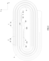
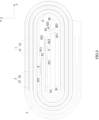
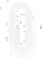
FIG. 7 is a schematic view of still another example of the wound-type cell, not according to the present invention, in which a first winding start end, a second winding start end and a third winding start end each are indicated by a dotted line frame. -
FIG. 8 is a schematic view of an embodiment of a first electrode tab formed in the wound-type cell according to the present invention, in which a first active material layer on a first current collector is omitted for the sake of clarity. -
FIG. 9 is a schematic view of another embodiment of the first electrode tab formed in the wound-type cell according to the present invention, in which the first active material layer on the first current collector is omitted for the sake of clarity. -
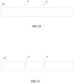
FIG. 10 is a schematic view of another embodiment of a second electrode tab formed in the wound-type cell according to the present invention, in which a second active material layer on a second current collector is omitted for the sake of clarity. -
FIG. 11 is a schematic view of another embodiment of the second electrode tab formed in the wound-type cell according to the present invention, in which the second active material layer on the second current collector is omitted for the sake of clarity. - Reference numerals are represented as follows:
- 1 first electrode plate
- 11 first current collector
111 blank first current collector - 12 first active material layer
- 13 first groove
- 11 first current collector
- 2 second electrode plate
- 21 second current collector
211 blank second current collector - 22 second active material layer
- 23 second groove
- 21 second current collector
- 3 separator
- 4 first electrode tab
- 5 second electrode tab
- E1 first winding start end
E11 first end - E2 second winding start end
E21 second end - E3 third winding start end
- C arc-shaped portion
- S1 first winding mandrel
- S11 first end surface
- S12 first side surface
- S2 second winding mandrel
- S21 second end surface
- S22 second side surface
- G clamping groove
- L length direction
- T thickness direction
- Hereinafter a wound-type cell and a winding mandrel according to the present invention will be described in detail in combination with the figures.
- Firstly, a wound-type cell according to a first aspect of the present invention will be described.
- Referring to
FIG. 2 through FIG. 11 , a wound-type cell according to the present disclosure comprises: afirst electrode plate 1 having a firstcurrent collector 11 and a firstactive material layer 12 coated on a surface of the firstcurrent collector 11; asecond electrode plate 2 having a secondcurrent collector 21 and a secondactive material layer 22 coated on a surface of the secondcurrent collector 21, and a second winding start end E2 of thesecond electrode plate 2 is positioned at an inner side of a first winding start end E1 of thefirst electrode plate 1 in a thickness direction T; aseparator 3 provided between thefirst electrode plate 1 and thesecond electrode plate 2 to separate thefirst electrode plate 1 from thesecond electrode plate 2; afirst electrode tab 4 electrically connected to the firstcurrent collector 11; and asecond electrode tab 5 electrically connected to the secondcurrent collector 21. A third winding start end E3 of theseparator 3 is positioned at an outer side of the second winding start end E2 of thesecond electrode plate 2 in a length direction L, extends along a direction away from a second end E21 of the second winding start end E2 and is not folded back. - In the wound-type cell according to the present invention, because the third winding start end E3 of the
separator 3 extends along the direction away from the second end E21 of the second winding start end E2 and is not folded back, there is no need to wind back theseparator 3 in large length as in the prior art, thereby reducing a usage amount of theseparator 3 and the cost of theseparator 3. In addition, the way that the third winding start end E3 of theseparator 3 extends can avoid the third winding start end E3 overlapping with the second winding start end E2 in the thickness direction T, thereby reducing a thickness of the wound-type cell and improve the energy density of the wound-type cell. At the same time, it is easy to realize automatic production of the wound-type cell of the present invention. - In an embodiment of a wound-type cell according to the present invention, a length of the third winding start end E3 of the
separator 3 is between 1 mm and 10 mm, preferably, the length of the third winding start end E3 of theseparator 3 is between 1 mm and 5 mm. - In an embodiment of the wound-type cell according to the present invention, referring to
FIG. 2 through FIG. 7 , a first half-circle of thesecond electrode plate 2 which is wound around the second winding start end E2 is a first layer of thesecond electrode plate 2, the first layer of thesecond electrode plate 2 and the second winding start end E2 face each other and a part of theseparator 3 is provided between the first layer of thesecond electrode plate 2 and the second winding start end E2. - In an embodiment of the wound-type cell according to the present invention, referring to
FIG. 2 through FIG. 7 , the third winding start end E3 of theseparator 3 is formed by two layers in the thickness direction T. The third winding start end E3 is a part of one layer and a part of the other layer which are clamped in a clamping groove G of a later mentioned winding mandrel; in the formed wound-type cell, the third winding start end E3 of theseparator 3 is two layers, preferably, the two layers are attached together. - In an embodiment of the wound-type cell according to the present invention, the
first electrode plate 1 may be a positive electrode plate or a negative electrode plate, correspondingly, thesecond electrode plate 2 may be a negative electrode plate or a positive electrode plate. Preferably, thefirst electrode plate 1 is a positive electrode plate and thesecond electrode plate 2 is a negative electrode plate, correspondingly, the firstactive material layer 12 is a positive active material layer, and specifically, the firstactive material layer 12 may be selected from at least one of lithium cobalt oxide (LiCoO2), lithium ferric phosphate (LiFePO4) and lithium manganese oxide (LiMn2O4). The secondactive material layer 22 is a negative active material layer, and specifically, the secondactive material layer 22 may be selected from at least one of carbon and silicon. - In an embodiment of the wound-type cell according to the present invention, the
first electrode tab 4 is provided as one or more in number (referring toFIG. 7 through FIG. 9 ). When thefirst electrode tab 4 of the wound-type cell is provided as more than one in number, thefirst electrode tabs 4 are preferably aligned in the thickness direction T, however it allows eachfirst electrode tab 4 to have a certain deviation in aligned position due to machining tolerance of eachfirst electrode tab 4. - In an embodiment of the wound-type cell according to the present invention, the
second electrode tab 5 is provided as one or more in number (referring toFIG. 7 ,FIG. 10 and FIG. 11 ). When thesecond electrode tab 5 of the wound-type cell is provided as more than one in number, thesecond electrode tabs 5 are preferably aligned in the thickness direction T, however it allows eachsecond electrode tab 5 to have a certain deviation in aligned position due to machining tolerance of eachsecond electrode tab 5. - In an embodiment of the wound-type cell according to the present invention, the first
current collector 11 is an aluminum foil, the secondcurrent collector 21 is a copper foil. - In an embodiment of the wound-type cell according to the present invention, a thickness of the
first electrode tab 4 is more than a thickness of the firstcurrent collector 11. This can ensure a connection strength and an overcurrent sectional area of thefirst electrode tab 4. - In an embodiment of the wound-type cell according to the present invention, a thickness of
second electrode tab 5 is more than a thickness of the secondcurrent collector 21. This can ensure a connection strength and an overcurrent sectional area of thesecond electrode tab 5. - In an embodiment of the wound-type cell according to the present invention, referring to
FIG. 2 through FIG. 6 , thefirst electrode plate 1 has a blank firstcurrent collector 111 which is positioned at the first winding start end E1 and is not coated with the firstactive material layer 12; correspondingly, thesecond electrode plate 2 has a blank secondcurrent collector 211 which is positioned at the second winding start end E2 and is not coated with the secondactive material layer 22. When thesecond electrode tab 5 is connected to the blank secondcurrent collector 211, the way that the third winding start end E3 of theseparator 3 extends can avoid superposition of a thickness of the third winding start end E3 and the thickness of thesecond electrode tab 5 in the thickness direction T, thereby reducing the thickness of the wound-type cell and improve the energy density of the wound-type cell. - In an embodiment of the wound-type cell according to the present invention, referring to
FIG. 2 through FIG. 6 , a side of the secondcurrent collector 21 which directly faces the blank firstcurrent collector 111 is not coated with the secondactive material layer 22. Because the blank firstcurrent collector 111 is not coated with the firstactive material layer 12, if the side of the secondcurrent collector 21 which directly faces the blank firstcurrent collector 111 is coated with the secondactive material layer 22, it is not only helpless to the capacity (lithium-ions cannot realize the reciprocating process of intercalation and deintercalation between the blank firstcurrent collector 111 and the secondcurrent collector 21 that directly faces the blank first current collector 111) but also increases the thickness of the wound-type cell and reduces the energy density of the wound-type cell. Therefore, the side of the secondcurrent collector 21 which directly faces the blank firstcurrent collector 111 may be not coated with the secondactive material layer 22, and this will avoid waste in material and improve the energy density of the wound-type cell. - In an embodiment of the wound-type cell according to the present invention, referring to
FIG. 2 through FIG. 6 , a side of the firstcurrent collector 11 which directly faces the blank secondcurrent collector 211 is not coated with the firstactive material layer 12. Because the blank secondcurrent collector 211 is not coated with the secondactive material layer 22, if the side of the firstcurrent collector 11 which directly faces the blank secondcurrent collector 211 is coated with the firstactive material layer 12, it is not only helpless to the capacity (lithium-ion cannot realize the reciprocating process of intercalation and deintercalation between the blank secondcurrent collector 211 and the firstcurrent collector 11 which directly faces the blank second current collector 211) but also increases the thickness of the wound-type cell and reduces the energy density of the wound-type cell. Therefore, the side of the firstcurrent collector 11 which directly faces the blank secondcurrent collector 211 may be not coated with the firstactive material layer 12, and this will avoid waste in material and improve the energy density of the wound-type cell. - In an embodiment of the wound-type cell according to the present invention, referring to
FIG. 2 through FIG. 6 , an inner side of an arc-shaped portion C of the secondcurrent collector 21 which directly faces a first end E11 of the first winding start end E1 is not coated with the secondactive material layer 22. Because the first end E11 of the first winding start end E1, which directly faces the inner side of the arc-shaped portion C of the secondcurrent collector 21, is not coated with the firstactive material layer 12, if the inner side of the arc-shaped portion C is coated with the secondactive material layer 22, it is not only helpless to the capacity (lithium-ion cannot realize the reciprocating process of intercalation and deintercalation between the inner side of the arc-shaped portion C of the secondcurrent collector 21 and the first end E11 of the first winding start end E1) but also increases the thickness of the wound-type cell and reduces the energy density of the wound-type cell. Therefore, the inner side of the arc-shaped portion C may be not coated with the secondactive material layer 22, and this will avoid waste in material and improve the energy density of the wound-type cell. - In an embodiment of the wound-type cell according to the present invention, referring to
FIG. 2 through FIG. 4 , the first end E11 of the first winding start end E1 is beyond the second end E21 of the second winding start end E2 in the length direction L and a position of thefirst electrode tab 4 is beyond the second end E21 of the second winding start end E2 in the length direction L. This winding way can further reduce the usage amount of theseparator 3 and in turn reduce the cost. - In an embodiment of the wound-type cell according to the present invention, referring to
FIG. 5 andFIG. 6 , the second end E21 of the second winding start end E2 is beyond the first end E11 of the first winding start end E1 in the length direction L and a position of thesecond electrode tab 5 is beyond the first end E11 of the first winding start end E1 in the length direction L. - In an embodiment of the wound-type cell according to the present invention, referring to
FIG. 7 , thefirst electrode plate 1 further has afirst groove 13, a bottom of thefirst groove 13 is a blank firstcurrent collector 111 which is exposed and a peripheral side of thefirst groove 13 is the firstactive material layer 12; correspondingly, thesecond electrode plate 2 further has asecond groove 23, a bottom of thesecond groove 23 is a blank secondcurrent collector 211 and a peripheral side of thesecond groove 23 is the secondactive material layer 22. - In an embodiment of the wound-type cell according to the present invention, the
first electrode tab 4 and the firstcurrent collector 11 are integrally formed. For example, referring toFIG. 8 , thefirst electrode tab 4 is formed by directly cutting the firstcurrent collector 11. More preferably, as shown inFIG. 9 , thefirst electrode tab 4 is formed by directly cutting a portion of the firstcurrent collector 11 and bending the cut portion. - In an embodiment of the wound-type cell according to the present invention, the
second electrode tab 5 and the secondcurrent collector 21 are integrally formed. For example, referring toFIG. 10 , thesecond electrode tab 5 is formed by directly cutting the secondcurrent collector 21. More preferably, as shown inFIG. 11 , thesecond electrode tab 5 is formed by directly cutting a portion of the secondcurrent collector 21 and bending the cut portion. - In an embodiment of the wound-type cell according to the present invention, the
first electrode tab 4 is formed separately and welded to the corresponding blank firstcurrent collector 111. - In an embodiment of the wound-type cell according to the present invention, the
second electrode tab 5 is formed separately and welded to the corresponding blank secondcurrent collector 211. - In an embodiment of the wound-type cell according to the present invention, the welding is laser welding, ultrasonic welding or resistance welding.
- The forming mode of the
first electrode tab 4 preferably uses the integrally forming mode. The forming mode of thesecond electrode tab 5 preferably uses the integrally forming mode. - Secondly, a winding mandrel according to a second aspect of the present disclosure will be described.
- Referring to
FIG. 2 through FIG. 5 , a winding mandrel according to a second aspect of the present disclosure is used for the wound-type cell according to the first aspect of the present invention, the winding mandrel comprises a first winding mandrel S1 and a second winding mandrel S2 which are sequentially provided along the length direction L, a first end surface S11 of the first winding mandrel S1 and a second end surface S21 of the second winding mandrel S2 face each other and form a clamping groove G; an end of the first end surface S11 which is away from the second winding start end E2 is beyond an end of the first end surface S11 which is close to the second winding start end E2 in the length direction L; correspondingly, an end of the second end surface S21 which is away from the second winding start end E2 is beyond an end of the second end surface S21 which is close to the second winding start end E2 in the length direction L. - In an embodiment of the wound-type cell according to the present invention, referring to
FIG. 2 through FIG. 5 , the first end surface S11and the second end surface S21 are parallel to each other. - In an embodiment of the wound-type cell according to the present disclosure, referring to
FIG. 2 through FIG. 5 , an angle between the first end surface S11 and a first side surface S12 of the first winding mandrel S1 which is close to the blank secondcurrent collector 211 is between 160 degrees and 110 degrees; correspondingly, an angle between the second end surface S21 and a second side surface S22 of the second winding mandrel S2 which is close to the blank secondcurrent collector 211 is between 20 degrees and 70 degrees.
Claims (3)
- A wound-type cell, comprising:a first electrode plate (1) having a first current collector (11) and a first active material layer (12) coated on a surface of the first current collector (11);a second electrode plate (2) having a second current collector (21) and a second active material layer (22) coated on a surface of the second current collector (21), and a second winding start end (E2) of the second electrode plate (2) being positioned at an inner side of a first winding start end (E1) of the first electrode plate (1) in a thickness direction (T), and the first winding start end (E1) and the second winding start end (E2) facing to a same direction in a length direction (L);a separator (3) provided between the first electrode plate (1) and the second electrode plate (2) to separate the first electrode plate (1) from the second electrode plate (2);a first electrode tab (4) electrically connected to the first current collector (11); anda second electrode tab (5) electrically connected to the second current collector (21);whereinthe first electrode plate (1) has a blank first current collector (111) which is positioned at the first winding start end (E1) and is not coated with the first active material layer (12);the second electrode plate (2) has a blank second current collector (211) which is positioned at the second winding start end (E2) and is not coated with the second active material layer (22);the first electrode tab (4) and the first current collector (11) are integrally formed, or the first electrode tab (4) is formed separately and welded to the corresponding blank first current collector (111);the second electrode tab (5) and the second current collector (21) are integrally formed, or the second electrode tab (5) is formed separately and welded to the corresponding blank second current collector (211);the first end (E11) of the first winding start end (E1) is beyond the second end (E21) of the second winding start end (E2) in the length direction (L) and a position of the first electrode tab (4) is beyond the second end (E21) of the second winding start end (E2) in the length direction (L);the separator (3) is formed by two layers sandwiching the second electrode plate (2), and a third winding start end (E3) of the separator (3) is formed by the two layers and positioned at an outer side of the second winding start end (E2) of the second electrode plate (2) in the length direction (L), extends along a direction away from the second end (E21) of the second winding start end (E2) and is not folded back;an inner side of an arc-shaped portion (C) of the second current collector (21) which directly faces a first end (E11) of the first winding start end (E1) is not coated with the second active material layer (22);a side of the second current collector (21) which directly faces the blank first current collector (111) is not coated with the second active material layer (22);a side of the first current collector (11) which directly faces the blank second current collector (211) is not coated with the first active material layer (12);the third winding start end (E3) of the separator (3) is positioned between the first electrode tab (4) and the second electrode tab (5) in the length direction (L).
- The wound-type cell according to Claim 1, wherein the first electrode plate (1) is a positive electrode plate; the second electrode plate (2) is a negative electrode plate.
- The wound-type cell according to Claim 1, wherein the first electrode tab (4) is provided as one or more in number; the second electrode tab (5) is provided as one or more in number.
Priority Applications (1)
| Application Number | Priority Date | Filing Date | Title |
|---|---|---|---|
| EP25162625.5A EP4546550A3 (en) | 2016-03-31 | 2017-03-07 | Wound-type cell |
Applications Claiming Priority (1)
| Application Number | Priority Date | Filing Date | Title |
|---|---|---|---|
| CN201610196793.8A CN107293806B (en) | 2016-03-31 | 2016-03-31 | wound battery |
Related Child Applications (2)
| Application Number | Title | Priority Date | Filing Date |
|---|---|---|---|
| EP25162625.5A Division-Into EP4546550A3 (en) | 2016-03-31 | 2017-03-07 | Wound-type cell |
| EP25162625.5A Division EP4546550A3 (en) | 2016-03-31 | 2017-03-07 | Wound-type cell |
Publications (2)
| Publication Number | Publication Date |
|---|---|
| EP3226338A1 EP3226338A1 (en) | 2017-10-04 |
| EP3226338B1 true EP3226338B1 (en) | 2025-04-23 |
Family
ID=58261562
Family Applications (2)
| Application Number | Title | Priority Date | Filing Date |
|---|---|---|---|
| EP25162625.5A Pending EP4546550A3 (en) | 2016-03-31 | 2017-03-07 | Wound-type cell |
| EP17159512.7A Active EP3226338B1 (en) | 2016-03-31 | 2017-03-07 | Wound-type cell |
Family Applications Before (1)
| Application Number | Title | Priority Date | Filing Date |
|---|---|---|---|
| EP25162625.5A Pending EP4546550A3 (en) | 2016-03-31 | 2017-03-07 | Wound-type cell |
Country Status (4)
| Country | Link |
|---|---|
| US (2) | US20170288273A1 (en) |
| EP (2) | EP4546550A3 (en) |
| CN (3) | CN116581395A (en) |
| ES (1) | ES3033188T3 (en) |
Families Citing this family (6)
| Publication number | Priority date | Publication date | Assignee | Title |
|---|---|---|---|---|
| CN110380108B (en) * | 2018-04-12 | 2021-10-08 | 宁德新能源科技有限公司 | Cell and electrochemical device having the same |
| CN109524606B (en) | 2018-11-05 | 2022-07-26 | 宁德新能源科技有限公司 | Pole piece, battery cell and battery |
| WO2022047674A1 (en) * | 2020-09-02 | 2022-03-10 | 宁德新能源科技有限公司 | Cell assembly and electrochemical device |
| CN113193163B (en) * | 2021-04-28 | 2022-08-12 | 宁德新能源科技有限公司 | Cells and electrical devices |
| CN113569379A (en) * | 2021-06-22 | 2021-10-29 | 惠州锂威新能源科技有限公司 | Three-dimensional modeling method for coiled battery cell |
| US20240234970A1 (en) * | 2023-01-11 | 2024-07-11 | Samsung Sdi Co., Ltd. | Cylindrical secondary battery |
Citations (3)
| Publication number | Priority date | Publication date | Assignee | Title |
|---|---|---|---|---|
| US20030180605A1 (en) * | 2001-08-06 | 2003-09-25 | Toru Mizutani | Non-aqueous electrolytic battery and its manufacturing method |
| US20150325832A1 (en) * | 2013-01-29 | 2015-11-12 | Kabushiki Kaisha Toyota Jidoshokki | Battery |
| WO2016013179A1 (en) * | 2014-07-23 | 2016-01-28 | 三洋電機株式会社 | Non-aqueous electrolyte secondary battery |
Family Cites Families (14)
| Publication number | Priority date | Publication date | Assignee | Title |
|---|---|---|---|---|
| US4000351A (en) * | 1971-05-10 | 1976-12-28 | The Gates Rubber Company | Spirally wound electrolytic cell and method for its winding |
| US6468692B1 (en) * | 1999-06-08 | 2002-10-22 | Ngk Insulators, Ltd. | Lithium secondary battery with sealed casing members |
| KR100449757B1 (en) * | 2001-11-23 | 2004-09-22 | 삼성에스디아이 주식회사 | Battery unit and secondary battery applying the such |
| KR100509606B1 (en) * | 2003-02-19 | 2005-08-22 | 삼성에스디아이 주식회사 | Jelly-roll type battery unit and winding method thereof and lithum secondary battery using the same |
| JP4968182B2 (en) * | 2008-05-29 | 2012-07-04 | ソニー株式会社 | Winding electrode body and non-aqueous electrolyte secondary battery |
| KR101009517B1 (en) * | 2008-06-23 | 2011-01-18 | 삼성에스디아이 주식회사 | Electrode Assembly and Lithium Secondary Battery Using the Same |
| CN201397861Y (en) | 2009-03-31 | 2010-02-03 | 天津力神电池股份有限公司 | Square lithium ion battery winding needle |
| KR101152515B1 (en) * | 2009-12-17 | 2012-06-01 | 삼성에스디아이 주식회사 | Electrode assembly and secondary battery using the same |
| KR101334625B1 (en) * | 2011-03-31 | 2013-11-29 | 주식회사 엘지화학 | Mandrel for Preparation of Jelly-roll Type Electrode Assembly |
| CN202395099U (en) * | 2011-12-20 | 2012-08-22 | 东莞市华创自动化设备有限公司 | Lamination device |
| KR101669216B1 (en) * | 2013-09-09 | 2016-10-25 | 삼성전자주식회사 | Electrode assembly and secondary battery including the same |
| CN203733899U (en) * | 2013-11-28 | 2014-07-23 | 东莞新能源科技有限公司 | Wound-type lithium ion cell |
| KR102238367B1 (en) * | 2015-03-13 | 2021-04-09 | 삼성에스디아이 주식회사 | electrode assembly and secondary battery having electrode assembly |
| CN205508963U (en) * | 2016-03-31 | 2016-08-24 | 宁德新能源科技有限公司 | Coiling type battery cell |
-
2016
- 2016-03-31 CN CN202310760777.7A patent/CN116581395A/en active Pending
- 2016-03-31 CN CN201610196793.8A patent/CN107293806B/en active Active
- 2016-03-31 CN CN202310759063.4A patent/CN116544526A/en active Pending
-
2017
- 2017-03-07 EP EP25162625.5A patent/EP4546550A3/en active Pending
- 2017-03-07 ES ES17159512T patent/ES3033188T3/en active Active
- 2017-03-07 EP EP17159512.7A patent/EP3226338B1/en active Active
- 2017-03-13 US US15/457,775 patent/US20170288273A1/en not_active Abandoned
-
2018
- 2018-10-31 US US16/177,087 patent/US10693192B2/en active Active
Patent Citations (4)
| Publication number | Priority date | Publication date | Assignee | Title |
|---|---|---|---|---|
| US20030180605A1 (en) * | 2001-08-06 | 2003-09-25 | Toru Mizutani | Non-aqueous electrolytic battery and its manufacturing method |
| US20150325832A1 (en) * | 2013-01-29 | 2015-11-12 | Kabushiki Kaisha Toyota Jidoshokki | Battery |
| WO2016013179A1 (en) * | 2014-07-23 | 2016-01-28 | 三洋電機株式会社 | Non-aqueous electrolyte secondary battery |
| US20170170525A1 (en) * | 2014-07-23 | 2017-06-15 | Sanyo Electric Co., Ltd. | Nonaqueous electrolyte secondary battery |
Also Published As
| Publication number | Publication date |
|---|---|
| US20190067746A1 (en) | 2019-02-28 |
| EP4546550A3 (en) | 2026-04-22 |
| CN116581395A (en) | 2023-08-11 |
| EP3226338A1 (en) | 2017-10-04 |
| CN107293806A (en) | 2017-10-24 |
| ES3033188T3 (en) | 2025-07-31 |
| US10693192B2 (en) | 2020-06-23 |
| US20170288273A1 (en) | 2017-10-05 |
| CN107293806B (en) | 2023-07-18 |
| CN116544526A (en) | 2023-08-04 |
| EP4546550A2 (en) | 2025-04-30 |
Similar Documents
| Publication | Publication Date | Title |
|---|---|---|
| US10693192B2 (en) | Wound-type cell | |
| CN111584823B (en) | Pole piece, battery core and battery | |
| US10833371B2 (en) | Wound-type cell | |
| JP6505859B2 (en) | Nonaqueous electrolyte secondary battery | |
| CN110476273A (en) | Secondary battery and method of manufacturing the same | |
| EP3196961B1 (en) | Secondary battery | |
| JP5790179B2 (en) | Winding type battery and method for manufacturing winding type battery | |
| CN103891024A (en) | Cell provided with spiral electrode, and method for manufacturing same | |
| JPWO2017010046A1 (en) | Winding battery | |
| JP2008300141A (en) | Multilayer secondary battery and manufacturing method thereof | |
| US20110293996A1 (en) | Stacked secondary battery and production method thereof | |
| US10158107B2 (en) | Battery comprising insulative films | |
| WO2020129880A1 (en) | Secondary battery and manufacturing method therefor | |
| JP7353302B2 (en) | secondary battery | |
| US11552374B2 (en) | Electrode for non-aqueous electrolyte secondary battery and non-aqueous electrolyte secondary battery | |
| US20200203776A1 (en) | Wound battery and manufacturing method of wound battery | |
| CN205508964U (en) | Coiling type battery cell | |
| CN205564899U (en) | Coiling type battery cell | |
| EP3654433B1 (en) | Electrode assembly and battery having the same | |
| CN205508963U (en) | Coiling type battery cell | |
| CN107302109A (en) | Takeup type battery core | |
| CN107302110A (en) | Takeup type battery core | |
| CN108886170B (en) | Pole piece, battery cell and energy storage device | |
| CN107293804B (en) | wound battery | |
| US9786886B2 (en) | Nonaqueous battery |
Legal Events
| Date | Code | Title | Description |
|---|---|---|---|
| PUAI | Public reference made under article 153(3) epc to a published international application that has entered the european phase |
Free format text: ORIGINAL CODE: 0009012 |
|
| STAA | Information on the status of an ep patent application or granted ep patent |
Free format text: STATUS: REQUEST FOR EXAMINATION WAS MADE |
|
| 17P | Request for examination filed |
Effective date: 20170307 |
|
| AK | Designated contracting states |
Kind code of ref document: A1 Designated state(s): AL AT BE BG CH CY CZ DE DK EE ES FI FR GB GR HR HU IE IS IT LI LT LU LV MC MK MT NL NO PL PT RO RS SE SI SK SM TR |
|
| AX | Request for extension of the european patent |
Extension state: BA ME |
|
| STAA | Information on the status of an ep patent application or granted ep patent |
Free format text: STATUS: EXAMINATION IS IN PROGRESS |
|
| 17Q | First examination report despatched |
Effective date: 20190219 |
|
| GRAP | Despatch of communication of intention to grant a patent |
Free format text: ORIGINAL CODE: EPIDOSNIGR1 |
|
| STAA | Information on the status of an ep patent application or granted ep patent |
Free format text: STATUS: GRANT OF PATENT IS INTENDED |
|
| RIC1 | Information provided on ipc code assigned before grant |
Ipc: H01M 50/538 20210101ALI20241029BHEP Ipc: H01M 50/536 20210101ALI20241029BHEP Ipc: H01M 10/0587 20100101ALI20241029BHEP Ipc: H01M 10/04 20060101AFI20241029BHEP |
|
| INTG | Intention to grant announced |
Effective date: 20241112 |
|
| GRAS | Grant fee paid |
Free format text: ORIGINAL CODE: EPIDOSNIGR3 |
|
| GRAA | (expected) grant |
Free format text: ORIGINAL CODE: 0009210 |
|
| STAA | Information on the status of an ep patent application or granted ep patent |
Free format text: STATUS: THE PATENT HAS BEEN GRANTED |
|
| P01 | Opt-out of the competence of the unified patent court (upc) registered |
Free format text: CASE NUMBER: APP_12048/2025 Effective date: 20250312 |
|
| RAP3 | Party data changed (applicant data changed or rights of an application transferred) |
Owner name: NINGDE AMPEREX TECHNOLOGY LIMITED |
|
| AK | Designated contracting states |
Kind code of ref document: B1 Designated state(s): AL AT BE BG CH CY CZ DE DK EE ES FI FR GB GR HR HU IE IS IT LI LT LU LV MC MK MT NL NO PL PT RO RS SE SI SK SM TR |
|
| REG | Reference to a national code |
Ref country code: GB Ref legal event code: FG4D |
|
| REG | Reference to a national code |
Ref country code: CH Ref legal event code: EP |
|
| REG | Reference to a national code |
Ref country code: DE Ref legal event code: R096 Ref document number: 602017089021 Country of ref document: DE |
|
| REG | Reference to a national code |
Ref country code: IE Ref legal event code: FG4D |
|
| REG | Reference to a national code |
Ref country code: NL Ref legal event code: FP |
|
| REG | Reference to a national code |
Ref country code: ES Ref legal event code: FG2A Ref document number: 3033188 Country of ref document: ES Kind code of ref document: T3 Effective date: 20250731 |
|
| REG | Reference to a national code |
Ref country code: AT Ref legal event code: MK05 Ref document number: 1788703 Country of ref document: AT Kind code of ref document: T Effective date: 20250423 |
|
| PG25 | Lapsed in a contracting state [announced via postgrant information from national office to epo] |
Ref country code: PT Free format text: LAPSE BECAUSE OF FAILURE TO SUBMIT A TRANSLATION OF THE DESCRIPTION OR TO PAY THE FEE WITHIN THE PRESCRIBED TIME-LIMIT Effective date: 20250825 Ref country code: FI Free format text: LAPSE BECAUSE OF FAILURE TO SUBMIT A TRANSLATION OF THE DESCRIPTION OR TO PAY THE FEE WITHIN THE PRESCRIBED TIME-LIMIT Effective date: 20250423 |
|
| REG | Reference to a national code |
Ref country code: LT Ref legal event code: MG9D |
|
| PG25 | Lapsed in a contracting state [announced via postgrant information from national office to epo] |
Ref country code: GR Free format text: LAPSE BECAUSE OF FAILURE TO SUBMIT A TRANSLATION OF THE DESCRIPTION OR TO PAY THE FEE WITHIN THE PRESCRIBED TIME-LIMIT Effective date: 20250724 Ref country code: NO Free format text: LAPSE BECAUSE OF FAILURE TO SUBMIT A TRANSLATION OF THE DESCRIPTION OR TO PAY THE FEE WITHIN THE PRESCRIBED TIME-LIMIT Effective date: 20250723 |
|
| PG25 | Lapsed in a contracting state [announced via postgrant information from national office to epo] |
Ref country code: PL Free format text: LAPSE BECAUSE OF FAILURE TO SUBMIT A TRANSLATION OF THE DESCRIPTION OR TO PAY THE FEE WITHIN THE PRESCRIBED TIME-LIMIT Effective date: 20250423 |
|
| PG25 | Lapsed in a contracting state [announced via postgrant information from national office to epo] |
Ref country code: BG Free format text: LAPSE BECAUSE OF FAILURE TO SUBMIT A TRANSLATION OF THE DESCRIPTION OR TO PAY THE FEE WITHIN THE PRESCRIBED TIME-LIMIT Effective date: 20250423 |
|
| PG25 | Lapsed in a contracting state [announced via postgrant information from national office to epo] |
Ref country code: HR Free format text: LAPSE BECAUSE OF FAILURE TO SUBMIT A TRANSLATION OF THE DESCRIPTION OR TO PAY THE FEE WITHIN THE PRESCRIBED TIME-LIMIT Effective date: 20250423 |
|
| PG25 | Lapsed in a contracting state [announced via postgrant information from national office to epo] |
Ref country code: AT Free format text: LAPSE BECAUSE OF FAILURE TO SUBMIT A TRANSLATION OF THE DESCRIPTION OR TO PAY THE FEE WITHIN THE PRESCRIBED TIME-LIMIT Effective date: 20250423 |
|
| PG25 | Lapsed in a contracting state [announced via postgrant information from national office to epo] |
Ref country code: RS Free format text: LAPSE BECAUSE OF FAILURE TO SUBMIT A TRANSLATION OF THE DESCRIPTION OR TO PAY THE FEE WITHIN THE PRESCRIBED TIME-LIMIT Effective date: 20250723 |
|
| PG25 | Lapsed in a contracting state [announced via postgrant information from national office to epo] |
Ref country code: IS Free format text: LAPSE BECAUSE OF FAILURE TO SUBMIT A TRANSLATION OF THE DESCRIPTION OR TO PAY THE FEE WITHIN THE PRESCRIBED TIME-LIMIT Effective date: 20250823 |
|
| PG25 | Lapsed in a contracting state [announced via postgrant information from national office to epo] |
Ref country code: LV Free format text: LAPSE BECAUSE OF FAILURE TO SUBMIT A TRANSLATION OF THE DESCRIPTION OR TO PAY THE FEE WITHIN THE PRESCRIBED TIME-LIMIT Effective date: 20250423 |
|
| PG25 | Lapsed in a contracting state [announced via postgrant information from national office to epo] |
Ref country code: DK Free format text: LAPSE BECAUSE OF FAILURE TO SUBMIT A TRANSLATION OF THE DESCRIPTION OR TO PAY THE FEE WITHIN THE PRESCRIBED TIME-LIMIT Effective date: 20250423 Ref country code: SM Free format text: LAPSE BECAUSE OF FAILURE TO SUBMIT A TRANSLATION OF THE DESCRIPTION OR TO PAY THE FEE WITHIN THE PRESCRIBED TIME-LIMIT Effective date: 20250423 |
|
| PG25 | Lapsed in a contracting state [announced via postgrant information from national office to epo] |
Ref country code: CZ Free format text: LAPSE BECAUSE OF FAILURE TO SUBMIT A TRANSLATION OF THE DESCRIPTION OR TO PAY THE FEE WITHIN THE PRESCRIBED TIME-LIMIT Effective date: 20250423 |
|
| PG25 | Lapsed in a contracting state [announced via postgrant information from national office to epo] |
Ref country code: EE Free format text: LAPSE BECAUSE OF FAILURE TO SUBMIT A TRANSLATION OF THE DESCRIPTION OR TO PAY THE FEE WITHIN THE PRESCRIBED TIME-LIMIT Effective date: 20250423 |
|
| REG | Reference to a national code |
Ref country code: DE Ref legal event code: R097 Ref document number: 602017089021 Country of ref document: DE |
|
| PG25 | Lapsed in a contracting state [announced via postgrant information from national office to epo] |
Ref country code: SK Free format text: LAPSE BECAUSE OF FAILURE TO SUBMIT A TRANSLATION OF THE DESCRIPTION OR TO PAY THE FEE WITHIN THE PRESCRIBED TIME-LIMIT Effective date: 20250423 Ref country code: RO Free format text: LAPSE BECAUSE OF FAILURE TO SUBMIT A TRANSLATION OF THE DESCRIPTION OR TO PAY THE FEE WITHIN THE PRESCRIBED TIME-LIMIT Effective date: 20250423 |
|
| PLBE | No opposition filed within time limit |
Free format text: ORIGINAL CODE: 0009261 |
|
| STAA | Information on the status of an ep patent application or granted ep patent |
Free format text: STATUS: NO OPPOSITION FILED WITHIN TIME LIMIT |
|
| REG | Reference to a national code |
Ref country code: CH Ref legal event code: L10 Free format text: ST27 STATUS EVENT CODE: U-0-0-L10-L00 (AS PROVIDED BY THE NATIONAL OFFICE) Effective date: 20260304 |
|
| PGFP | Annual fee paid to national office [announced via postgrant information from national office to epo] |
Ref country code: NL Payment date: 20260213 Year of fee payment: 10 |
|
| 26N | No opposition filed |
Effective date: 20260126 |
|
| PGFP | Annual fee paid to national office [announced via postgrant information from national office to epo] |
Ref country code: GB Payment date: 20260202 Year of fee payment: 10 |
|
| PGFP | Annual fee paid to national office [announced via postgrant information from national office to epo] |
Ref country code: DE Payment date: 20260204 Year of fee payment: 10 |
|
| PGFP | Annual fee paid to national office [announced via postgrant information from national office to epo] |
Ref country code: IT Payment date: 20260220 Year of fee payment: 10 |
|
| PGFP | Annual fee paid to national office [announced via postgrant information from national office to epo] |
Ref country code: FR Payment date: 20260209 Year of fee payment: 10 |