EP3226148A1 - Electromagnetic field analysis method for anisotropic conductive material - Google Patents
Electromagnetic field analysis method for anisotropic conductive material Download PDFInfo
- Publication number
- EP3226148A1 EP3226148A1 EP17157394.2A EP17157394A EP3226148A1 EP 3226148 A1 EP3226148 A1 EP 3226148A1 EP 17157394 A EP17157394 A EP 17157394A EP 3226148 A1 EP3226148 A1 EP 3226148A1
- Authority
- EP
- European Patent Office
- Prior art keywords
- electromagnetic field
- analysis
- analysis method
- conductive material
- anisotropic conductive
- Prior art date
- Legal status (The legal status is an assumption and is not a legal conclusion. Google has not performed a legal analysis and makes no representation as to the accuracy of the status listed.)
- Granted
Links
Images


Classifications
-
- G—PHYSICS
- G06—COMPUTING OR CALCULATING; COUNTING
- G06F—ELECTRIC DIGITAL DATA PROCESSING
- G06F30/00—Computer-aided design [CAD]
- G06F30/20—Design optimisation, verification or simulation
- G06F30/23—Design optimisation, verification or simulation using finite element methods [FEM] or finite difference methods [FDM]
-
- G—PHYSICS
- G01—MEASURING; TESTING
- G01N—INVESTIGATING OR ANALYSING MATERIALS BY DETERMINING THEIR CHEMICAL OR PHYSICAL PROPERTIES
- G01N27/00—Investigating or analysing materials by the use of electric, electrochemical, or magnetic means
- G01N27/60—Investigating or analysing materials by the use of electric, electrochemical, or magnetic means by investigating electrostatic variables, e.g. electrographic flaw testing
-
- G—PHYSICS
- G06—COMPUTING OR CALCULATING; COUNTING
- G06F—ELECTRIC DIGITAL DATA PROCESSING
- G06F30/00—Computer-aided design [CAD]
- G06F30/20—Design optimisation, verification or simulation
-
- G—PHYSICS
- G01—MEASURING; TESTING
- G01R—MEASURING ELECTRIC VARIABLES; MEASURING MAGNETIC VARIABLES
- G01R29/00—Arrangements for measuring or indicating electric quantities not covered by groups G01R19/00 - G01R27/00
- G01R29/08—Measuring electromagnetic field characteristics
- G01R29/0807—Measuring electromagnetic field characteristics characterised by the application
- G01R29/0814—Field measurements related to measuring influence on or from apparatus, components or humans, e.g. in ESD, EMI, EMC, EMP testing, measuring radiation leakage; detecting presence of micro- or radiowave emitters; dosimetry; testing shielding; measurements related to lightning
- G01R29/0842—Measurements related to lightning, e.g. measuring electric disturbances, warning systems
-
- G—PHYSICS
- G01—MEASURING; TESTING
- G01R—MEASURING ELECTRIC VARIABLES; MEASURING MAGNETIC VARIABLES
- G01R31/00—Arrangements for testing electric properties; Arrangements for locating electric faults; Arrangements for electrical testing characterised by what is being tested not provided for elsewhere
- G01R31/005—Testing of electric installations on transport means
- G01R31/008—Testing of electric installations on transport means on air- or spacecraft, railway rolling stock or sea-going vessels
-
- G—PHYSICS
- G06—COMPUTING OR CALCULATING; COUNTING
- G06F—ELECTRIC DIGITAL DATA PROCESSING
- G06F2113/00—Details relating to the application field
- G06F2113/26—Composites
-
- G—PHYSICS
- G06—COMPUTING OR CALCULATING; COUNTING
- G06F—ELECTRIC DIGITAL DATA PROCESSING
- G06F2113/00—Details relating to the application field
- G06F2113/28—Fuselage, exterior or interior
Definitions
- the present invention relates to electromagnetic field analysis methods for anisotropic conductive materials having anisotropic conductivity.
- FDTD finite-difference time-domain
- CFRP carbon fiber reinforced plastic
- a known analysis method in the related art that deals with anisotropic conductivity involves the use of conductivity tensor representation.
- the anisotropic conductivity is expressed by an off-diagonal element of a conductivity tensor occurring when the conductivity defined on a three-orthogonal-axes coordinate system is rotated about a z-axis. Then, the conductivity tensor is applied to Maxwell's equation, and a finite difference method is used, whereby a discretized expression is obtained for each axis.
- An aspect of the present invention provides an electromagnetic field analysis method for an anisotropic conductive material, in which an analysis grid having a first side and a second side that are orthogonal to each other is used to analyze an electromagnetic property of an anisotropic conductive material in which conductivity in a first direction is different from conductivity in a second direction.
- One or both of the first direction and the second direction are parallel to a direction different from either one of the first side and the second side of the analysis grid, and one electromagnetic field component located on the first side and extending along the second side is calculated based on electromagnetic field components that are located on the second sides surrounding the one electromagnetic field component and that extend along the second sides.
- the one electromagnetic field component may be calculated as an average value of the electromagnetic field components.
- the one electromagnetic field component may be calculated based on any of the electromagnetic field components included in the anisotropic conductive material.
- the analysis grid may be a cubical analysis grid extending along three orthogonal axes.
- the electromagnetic field components may include four electromagnetic field components respectively located on four of the second sides coupled to the first side at two nodal points of opposite ends of the first side on which the one electromagnetic field component is located.
- the electromagnetic field analysis method may use a finite-difference time-domain method.
- the analysis grid may be a cubical analysis grid extending along three orthogonal axes.
- a conductivity tensor obtained when conductivity defined in a coordinate system of the three orthogonal axes is rotated about an axis orthogonal to both of the first direction and the second direction may be applied to Ampere's expression and may subsequently be discretized by using a finite difference method.
- an undefined electromagnetic field component included in the discretized expression may be calculated as the one electromagnetic field component from the electromagnetic field components.
- the anisotropic conductive material may be fiber reinforced plastic in which plastic is reinforced with conductive fiber extending in either one of the first direction and the second direction.
- the electromagnetic property, such as the electric current distribution, of a material having anisotropic conductivity is calculated by using a finite-difference time-domain (FDTD) method.
- the FDTD method is a numerical analysis method that involves calculating electromagnetic field components along three orthogonal axes by using a cubical analysis grid (Yee grid) in which the respective sides extend along three orthogonal xyz axes.
- the anisotropic conductive material being analyzed has anisotropic conductivity in which the conductivity in a certain direction differs from that in another direction.
- the anisotropic conductive material is fiber reinforced plastic (FRP) in which plastic is reinforced with conductive fibers.
- FRP fiber reinforced plastic
- the conductivity in the fiber direction is higher than that in another direction, so that electric current flows readily in the fiber direction.
- an analysis technique using anisotropic-conductivity tensor representation is employed.
- the anisotropic conductivity in the direction different from the three orthogonal axes can be derived by using a relational expression of a current density J and an electric field E expressed with expression (1) below and rotating the current density and the electric field about the z-axis by an angle ⁇ , as in expression (2) below.
- ⁇ p denotes the conductivity in the fiber direction
- ⁇ t denotes the conductivity in a direction orthogonal to the fiber direction within the x-y plane.
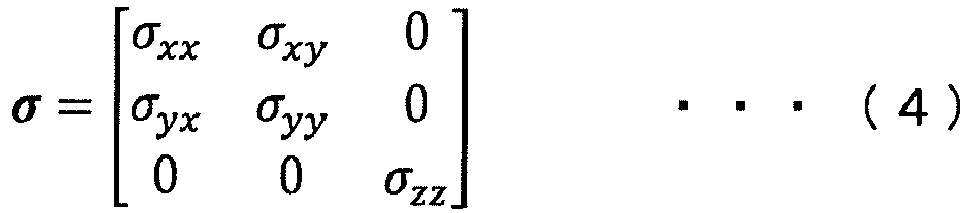
- the conductivity of the material having anisotropy in any direction within the x-y plane can be expressed with expression (4) below, assuming that components ⁇ xx , ⁇ yy , and ⁇ zz correspond to the respective axial directions and off-diagonal elements mentioned above are denoted by ⁇ xy , and ⁇ yx .
- ⁇ ⁇ xx ⁇ xy 0 ⁇ yx ⁇ yy 0 0 0 ⁇ zz
- each parameter is satisfied at any one point in a three-dimensional space.
- discretized components E x , E y , and E z exist at different positions in the analysis grid.
- the electric field in the Yee grid is located in an area corresponding to the sides of the grid, and the components E x , E y , and E z are located on different sides (i.e., sides extending along the respective axes) of each grid. In discretization, the position of the electric field has to be clarified.
- the electromagnetic field analysis method does not use the assumption based on expression (10) above but approximates the value of the undefined component E x (indicated by a solid arrow in Fig. 1A ) as an average value of four components E x (indicated by voided arrows in Fig. 1A ), which are components E x that are located on sides where the components E x are defined (referred to as "defined components E x " hereinafter) and that are located on four sides surrounding the undefined component E x . Furthermore, the same applies to the component E y . Specifically, as illustrated in Fig.
- the value of the undefined component E y is approximated as an average value of four components E y , which are components E y that are located on sides where the components E y are defined (referred to as “defined components E y " hereinafter) and that are located on four sides surrounding the undefined component E y .
- i , j 1 2 , k E x n
- i + 1 2 , j , k E y n
- the undefined component E x is located on a side extending along a peripheral edge of the object being analyzed (i.e., the boundary with the peripheral space)
- only two defined components E x (within the boundary), included in the object being analyzed, of the four defined components E x to be averaged out are used to calculate the undefined component E x , and the values of the two remaining defined components E x included in the peripheral space are not used.
- the undefined component E x may be calculated based on a plurality of surrounding defined components E x , and the method of interpolating the undefined component E x from the positions and the number of defined components E x and from a plurality of defined components E x is not limited to that described above.
- an iterative method as typified by the Gauss-Seidel method, is applied as a more efficient method, instead of simultaneously using expression (7) and expression (8), such that the calculation is performed repeatedly until the rates of change of the components E x and E y become sufficiently small (lower than or equal to a predetermined threshold value). Then, during this repeated calculation process, the undefined components E x and E y are interpolated, as appropriate, with a plurality of components E x and E y by using expression (11) and expression (12).
- the electromagnetic field analysis method according to this embodiment is compared with the above-described analysis method in the related art to study the validity of the two methods.
- An analytic model used for performing the comparison is a unidirectional-material flat plate, as illustrated in Fig. 2A .
- This flat plate has a size of 300 mm by 300 mm by 10 mm, and the number of mesh is 21x21x1.
- a metal rod defined by a single line on a grid is coupled to an object being analyzed and an absorption boundary so as to define the metal rod as an electrode.
- An applicator electrode and a return electrode are coupled to opposite ends of the flat plate on a diagonal line thereof that is parallel to the fiber direction.
- the applied current has a peak value of 3 kA in a waveform of component A for an aircraft lightning test regulated under SAE ARP-5416.
- the current density is calculated in this analytic example, the current density to be determined in the electromagnetic field analysis method according to this embodiment has to be calculated in view of the effect of an off-diagonal element of a conductivity tensor, as indicated in expression (13) and expression (14) below.
- J x ⁇ xx E x + ⁇ xy E y
- J y ⁇ yx E x + ⁇ yy E y
- the current density which is the calculation result described above, is a value at each side of the grid.
- the current density in each cell is calculated as an average value of current densities surrounding the cell.
- Figs. 2B and 2C illustrate results of this analytic example and illustrate the current density after 6.4 ⁇ s at which the applied current reaches the peak value.
- Fig. 2B corresponds to the analysis method in the related art
- Fig. 2C corresponds to the electromagnetic field analysis method according to this embodiment.
- Each analysis result indicates the electric current distribution displayed by filling in the cells formed by the analysis grid using color gradation.
- the vector directions formed by components J x and J y in expression (12) and expression (13) are indicated by arrows.
- the current direction in each cell is parallel to the fiber direction, but current concentration caused by anisotropy cannot be calculated.
- an undefined component E x located on a side extending along the y-axis of the analysis grid is calculated based on a plurality of defined components E x surrounding the undefined component E x and located on sides extending along the x-axis, and an undefined component E y is similarly calculated based on a plurality of defined components E y .
- the undefined components E x and E y are calculated by interpolation based on the plurality of surrounding defined components E x and E y .
- an electromagnetic field analysis of an anisotropic conductive material having anisotropic conductivity can be performed with high accuracy.
- the anisotropic conductive material to be analyzed is fiber reinforced plastic in the above embodiment
- the anisotropic conductive material according to the embodiment of the present invention is not particularly limited so long as the conductivity in a predetermined first direction is different from that in another direction, and does not have to be fiber reinforced plastic.
Landscapes
- Engineering & Computer Science (AREA)
- Physics & Mathematics (AREA)
- Theoretical Computer Science (AREA)
- General Physics & Mathematics (AREA)
- Computer Hardware Design (AREA)
- Evolutionary Computation (AREA)
- Geometry (AREA)
- General Engineering & Computer Science (AREA)
- Chemical & Material Sciences (AREA)
- Chemical Kinetics & Catalysis (AREA)
- Electrochemistry (AREA)
- Health & Medical Sciences (AREA)
- Life Sciences & Earth Sciences (AREA)
- Analytical Chemistry (AREA)
- Biochemistry (AREA)
- General Health & Medical Sciences (AREA)
- Immunology (AREA)
- Pathology (AREA)
- Shielding Devices Or Components To Electric Or Magnetic Fields (AREA)
Abstract
Description
- The present invention relates to electromagnetic field analysis methods for anisotropic conductive materials having anisotropic conductivity.
- When designing airframes of aircrafts, countermeasures against lightning are necessary for preventing, for instance, fuel ignition occurring from sparks caused by lightning strikes. With regard to such a countermeasure against lightning, it is important to clarify the electric current distribution within the airframe when struck by lightning. In order to achieve this, a highly-accurate electromagnetic field analysis method is desired.
- With regard to an electromagnetic field analysis method of this kind, a finite-difference time-domain (FDTD) method is widely used (for instance, see
JP-2001-183404 A - As a structural material for the airframe of an aircraft, a composite material, such as carbon fiber reinforced plastic (CFRP) with high specific strength, is being put to practical use. When performing an electromagnetic field analysis of such a composite material, since each fiber is electrically conductive, the anisotropic conductivity in the fiber direction has to be taken into consideration.
- A known analysis method in the related art that deals with anisotropic conductivity involves the use of conductivity tensor representation.
- In this analysis method, the anisotropic conductivity is expressed by an off-diagonal element of a conductivity tensor occurring when the conductivity defined on a three-orthogonal-axes coordinate system is rotated about a z-axis. Then, the conductivity tensor is applied to Maxwell's equation, and a finite difference method is used, whereby a discretized expression is obtained for each axis.
- In the definition of a Yee grid, electromagnetic fields of the respective discretized axes are located at different positions in the grid. However, the obtained discretized expression has a mixture of electromagnetic fields at different positions (i.e., electromagnetic fields at positions not defined in the Yee grid). Thus, the calculation cannot be performed with the expression in this state (this will be described later in detail in the embodiment). In the analysis method in the related art, the analysis is attempted based on an assumption that these electric fields at different positions are identical to each other.
- However, simply defining these electric fields at different positions as being identical to each other, as in the above-described analysis method in the related art, leads to reduced approximation accuracy.
- It is desirable to perform an electromagnetic field analysis of an anisotropic conductive material having anisotropic conductivity with higher accuracy than in the related art. This object is achieved with the features of the claims.
- An aspect of the present invention provides an electromagnetic field analysis method for an anisotropic conductive material, in which an analysis grid having a first side and a second side that are orthogonal to each other is used to analyze an electromagnetic property of an anisotropic conductive material in which conductivity in a first direction is different from conductivity in a second direction. One or both of the first direction and the second direction are parallel to a direction different from either one of the first side and the second side of the analysis grid, and one electromagnetic field component located on the first side and extending along the second side is calculated based on electromagnetic field components that are located on the second sides surrounding the one electromagnetic field component and that extend along the second sides.
- The one electromagnetic field component may be calculated as an average value of the electromagnetic field components.
- In a case where the one electromagnetic field component is located on the first side extending along a peripheral edge of the anisotropic conductive material, the one electromagnetic field component may be calculated based on any of the electromagnetic field components included in the anisotropic conductive material.
- The analysis grid may be a cubical analysis grid extending along three orthogonal axes. The electromagnetic field components may include four electromagnetic field components respectively located on four of the second sides coupled to the first side at two nodal points of opposite ends of the first side on which the one electromagnetic field component is located.
- The electromagnetic field analysis method may use a finite-difference time-domain method. The analysis grid may be a cubical analysis grid extending along three orthogonal axes. A conductivity tensor obtained when conductivity defined in a coordinate system of the three orthogonal axes is rotated about an axis orthogonal to both of the first direction and the second direction may be applied to Ampere's expression and may subsequently be discretized by using a finite difference method. When performing calculation repeatedly by applying an iterative method to the discretized expression, an undefined electromagnetic field component included in the discretized expression may be calculated as the one electromagnetic field component from the electromagnetic field components.
- In the electromagnetic field analysis method according to the above aspect, the anisotropic conductive material may be fiber reinforced plastic in which plastic is reinforced with conductive fiber extending in either one of the first direction and the second direction.
- An embodiment of the present invention will be described below with reference to the drawings.
-
Figs. 1A and 1B illustrate calculation methods for determining an undefined electromagnetic field component from a plurality of defined electromagnetic field components; and -
Fig. 2A illustrates an analytic model in an analytic example,Fig. 2B illustrates an analysis result obtained in accordance with an analysis method in the related art, andFig. 2C illustrates an analysis result obtained in accordance with an electromagnetic field analysis method according to an embodiment. - In an electromagnetic field analysis method for an anisotropic conductive material (simply referred to as "electromagnetic field analysis method" hereinafter) according to this embodiment, the electromagnetic property, such as the electric current distribution, of a material having anisotropic conductivity is calculated by using a finite-difference time-domain (FDTD) method. The FDTD method is a numerical analysis method that involves calculating electromagnetic field components along three orthogonal axes by using a cubical analysis grid (Yee grid) in which the respective sides extend along three orthogonal xyz axes.
- The anisotropic conductive material being analyzed has anisotropic conductivity in which the conductivity in a certain direction differs from that in another direction. In this embodiment, the anisotropic conductive material is fiber reinforced plastic (FRP) in which plastic is reinforced with conductive fibers. In such FRP, the conductivity in the fiber direction is higher than that in another direction, so that electric current flows readily in the fiber direction.
- In the electromagnetic field analysis method according to this embodiment, an analysis technique using anisotropic-conductivity tensor representation is employed.
- This analysis technique will be described in detail below.
- In view of a state where the object being analyzed is rotated about an axis orthogonal to the fiber direction, the anisotropic conductivity in the direction different from the three orthogonal axes can be derived by using a relational expression of a current density J and an electric field E expressed with expression (1) below and rotating the current density and the electric field about the z-axis by an angle θ, as in expression (2) below. Each underlined part in expression (3) obtained by modifying expression (2) is an off-diagonal element of a conductivity tensor. This off-diagonal element is zero when θ = 0.


- In this case, σp denotes the conductivity in the fiber direction, and σt denotes the conductivity in a direction orthogonal to the fiber direction within the x-y plane.
- The conductivity of the material having anisotropy in any direction within the x-y plane can be expressed with expression (4) below, assuming that components σxx, σyy, and σzz correspond to the respective axial directions and off-diagonal elements mentioned above are denoted by σxy, and σyx.
- In order to directly solve Maxwell's equation in the FDTD method, expression (6) below is obtained by applying expression (4) to Ampere's expression (5) in Maxwell's equation.


- In expression (6), each parameter is satisfied at any one point in a three-dimensional space. However, in the definition of a Yee grid in the FDTD method, discretized components Ex, Ey, and Ez exist at different positions in the analysis grid. The electric field in the Yee grid is located in an area corresponding to the sides of the grid, and the components Ex, Ey, and Ez are located on different sides (i.e., sides extending along the respective axes) of each grid. In discretization, the position of the electric field has to be clarified.
- By denoting the position of the electric field as "|i, j, k" and discretizing expression (6) using a finite difference method, expression (7) to expression (9) below are obtained.


- In expression (7) and expression (8), there is a mixture of electric fields at different positions. Specifically, in a Yee grid, there is a component Ex (referred to as "undefined component Ex" hereinafter) located on a side where the component Ex is not defined (i.e., the side where a component Ey is defined along the y-axis), and a component Ey (referred to as "undefined component Ey" hereinafter) located on a side where the component Ey is not defined (i.e., the side where the component Ex is defined along the x-axis). Therefore, the calculations cannot be performed using the expressions in these states.
- With respect to this problem, the analysis technique in the related art simultaneously uses expression (7) and expression (8), assuming that these electric fields at different positions are identical to each other, as in expression (10) below.

- However, defining these electric fields at different positions as being identical to each other leads to reduced approximation accuracy.
- As illustrated in
Fig. 1A , the electromagnetic field analysis method according to this embodiment does not use the assumption based on expression (10) above but approximates the value of the undefined component Ex (indicated by a solid arrow inFig. 1A ) as an average value of four components Ex (indicated by voided arrows inFig. 1A ), which are components Ex that are located on sides where the components Ex are defined (referred to as "defined components Ex" hereinafter) and that are located on four sides surrounding the undefined component Ex. Furthermore, the same applies to the component Ey. Specifically, as illustrated inFig. 1B , similar to the case of the component Ex, the value of the undefined component Ey is approximated as an average value of four components Ey, which are components Ey that are located on sides where the components Ey are defined (referred to as "defined components Ey" hereinafter) and that are located on four sides surrounding the undefined component Ey. - In detail, the undefined component Ex and the undefined component Ey are calculated using expression (11) and expression (12) below.


- However, if the undefined component Ex is located on a side extending along a peripheral edge of the object being analyzed (i.e., the boundary with the peripheral space), only two defined components Ex (within the boundary), included in the object being analyzed, of the four defined components Ex to be averaged out are used to calculate the undefined component Ex, and the values of the two remaining defined components Ex included in the peripheral space are not used.
- For instance, in
Fig. 1A , in a case where the right analysis grid is included in the object being analyzed and the left analysis grid belongs to the peripheral space, only two defined components Ex of i + 1/2 are used for calculating the undefined component Ex. - The same applies to the undefined component Ey.
- The undefined component Ex may be calculated based on a plurality of surrounding defined components Ex, and the method of interpolating the undefined component Ex from the positions and the number of defined components Ex and from a plurality of defined components Ex is not limited to that described above.
- If expression (11) and expression (12) above are substituted into expression (7) and expression (8), there would be eight unknowns for Ex and Ey. By applying them to various locations on the analysis grids and simultaneously applying them in the entire analytic space to configure a matrix, an analysis is possible.
- However, in this embodiment, an iterative method, as typified by the Gauss-Seidel method, is applied as a more efficient method, instead of simultaneously using expression (7) and expression (8), such that the calculation is performed repeatedly until the rates of change of the components Ex and Ey become sufficiently small (lower than or equal to a predetermined threshold value). Then, during this repeated calculation process, the undefined components Ex and Ey are interpolated, as appropriate, with a plurality of components Ex and Ey by using expression (11) and expression (12).
- Consequently, the electromagnetic property of the anisotropic conductive material can be analyzed.
- Next, an analytic example using the electromagnetic field analysis method according to this embodiment will be described.
- In this analytic example, the electromagnetic field analysis method according to this embodiment is compared with the above-described analysis method in the related art to study the validity of the two methods.
- An analytic model used for performing the comparison is a unidirectional-material flat plate, as illustrated in
Fig. 2A . This flat plate has a size of 300 mm by 300 mm by 10 mm, and the number of mesh is 21x21x1. - A metal rod defined by a single line on a grid is coupled to an object being analyzed and an absorption boundary so as to define the metal rod as an electrode. An applicator electrode and a return electrode are coupled to opposite ends of the flat plate on a diagonal line thereof that is parallel to the fiber direction.
- The applied current has a peak value of 3 kA in a waveform of component A for an aircraft lightning test regulated under SAE ARP-5416.
- Although the current density is calculated in this analytic example, the current density to be determined in the electromagnetic field analysis method according to this embodiment has to be calculated in view of the effect of an off-diagonal element of a conductivity tensor, as indicated in expression (13) and expression (14) below.


- Because the electric field in a Yee grid is located in an area corresponding to the sides of each grid, the current density, which is the calculation result described above, is a value at each side of the grid. The current density in each cell is calculated as an average value of current densities surrounding the cell.
-
Figs. 2B and 2C illustrate results of this analytic example and illustrate the current density after 6.4 µs at which the applied current reaches the peak value. Specifically,Fig. 2B corresponds to the analysis method in the related art, whereasFig. 2C corresponds to the electromagnetic field analysis method according to this embodiment. - Each analysis result indicates the electric current distribution displayed by filling in the cells formed by the analysis grid using color gradation. In order to display the direction in which the electric current flows in each cell, the vector directions formed by components Jx and Jy in expression (12) and expression (13) are indicated by arrows.
- As illustrated in
Fig. 2B , in the analysis method in the related art, the current direction in each cell is parallel to the fiber direction, but current concentration caused by anisotropy cannot be calculated. - In contrast, as illustrated in
Fig. 2C , in the electromagnetic field analysis method according to this embodiment, strong electric current distribution is calculated on the diagonal line of the flat plate in a manner such as to couple the two electrodes to each other. Thus, it can be considered that electric current distribution according to the anisotropic conductivity in the fiber direction is reproduced. - Accordingly, in the electromagnetic field analysis method according to this embodiment, an undefined component Ex located on a side extending along the y-axis of the analysis grid is calculated based on a plurality of defined components Ex surrounding the undefined component Ex and located on sides extending along the x-axis, and an undefined component Ey is similarly calculated based on a plurality of defined components Ey.
- In other words, the undefined components Ex and Ey are calculated by interpolation based on the plurality of surrounding defined components Ex and Ey.
- Therefore, as compared with the related art in which it is simply defined that the electric fields at different positions are identical to each other, an electromagnetic field analysis of an anisotropic conductive material having anisotropic conductivity can be performed with high accuracy.
- An embodiment to which the present invention is applicable is not limited to the above embodiment, and modifications are permissible, as appropriate, so long as they do not depart from the scope of the invention.
- For instance, although the anisotropic conductive material to be analyzed is fiber reinforced plastic in the above embodiment, the anisotropic conductive material according to the embodiment of the present invention is not particularly limited so long as the conductivity in a predetermined first direction is different from that in another direction, and does not have to be fiber reinforced plastic.
Claims (6)
- An electromagnetic field analysis method for an anisotropic conductive material, wherein an analysis grid having a first side and a second side that are orthogonal to each other is used to analyze an electromagnetic property of an anisotropic conductive material in which conductivity in a first direction is different from conductivity in a second direction,
wherein one or both of the first direction and the second direction are parallel to a direction different from either one of the first side and the second side of the analysis grid, and
wherein one electromagnetic field component located on the first side and extending along the second side is calculated based on electromagnetic field components that are located on the second sides surrounding the one electromagnetic field component and that extend along the second sides. - The electromagnetic field analysis method according to Claim 1,
wherein the one electromagnetic field component is calculated as an average value of the electromagnetic field components. - The electromagnetic field analysis method according to one of Claims 1 and 2,
wherein in a case where the one electromagnetic field component is located on the first side extending along a peripheral edge of the anisotropic conductive material, the one electromagnetic field component is calculated based on any of the electromagnetic field components included in the anisotropic conductive material. - The electromagnetic field analysis method according to any one of Claims 1 to 3,
wherein the analysis grid is a cubical analysis grid extending along three orthogonal axes, and
wherein the electromagnetic field components comprise four electromagnetic field components respectively located on four of the second sides coupled to the first side at two nodal points of opposite ends of the first side on which the one electromagnetic field component is located. - The electromagnetic field analysis method according to any one of Claims 1 to 4,
wherein the electromagnetic field analysis method uses a finite-difference time-domain method,
wherein the analysis grid is a cubical analysis grid extending along three orthogonal axes,
wherein a conductivity tensor obtained when conductivity defined in a coordinate system of the three orthogonal axes is rotated about an axis orthogonal to both of the first direction and the second direction is applied to Ampere's expression and is subsequently discretized by using a finite difference method, and
wherein when performing calculation repeatedly by applying an iterative method to the discretized expression, an undefined electromagnetic field component included in the discretized expression is calculated as the one electromagnetic field component from the electromagnetic field components. - The electromagnetic field analysis method according to any one of Claims 1 to 5,
wherein the anisotropic conductive material is fiber reinforced plastic in which plastic is reinforced with conductive fiber extending in either one of the first direction and the second direction.
Applications Claiming Priority (1)
| Application Number | Priority Date | Filing Date | Title |
|---|---|---|---|
| JP2016069876A JP6317776B2 (en) | 2016-03-31 | 2016-03-31 | Lightning protection test method for aircraft fuselage structural materials |
Publications (2)
| Publication Number | Publication Date |
|---|---|
| EP3226148A1 true EP3226148A1 (en) | 2017-10-04 |
| EP3226148B1 EP3226148B1 (en) | 2018-11-21 |
Family
ID=58191272
Family Applications (1)
| Application Number | Title | Priority Date | Filing Date |
|---|---|---|---|
| EP17157394.2A Active EP3226148B1 (en) | 2016-03-31 | 2017-02-22 | Electromagnetic field analysis method for anisotropic conductive material |
Country Status (4)
| Country | Link |
|---|---|
| US (1) | US10119936B2 (en) |
| EP (1) | EP3226148B1 (en) |
| JP (1) | JP6317776B2 (en) |
| ES (1) | ES2710619T3 (en) |
Cited By (1)
| Publication number | Priority date | Publication date | Assignee | Title |
|---|---|---|---|---|
| CN110119586A (en) * | 2019-05-21 | 2019-08-13 | 中煤科工集团西安研究院有限公司 | Axial conductivity anisotropy transient electromagnetic three-component three-dimensional FDTD forward modeling method |
Families Citing this family (2)
| Publication number | Priority date | Publication date | Assignee | Title |
|---|---|---|---|---|
| JP2021110997A (en) * | 2020-01-07 | 2021-08-02 | 住友重機械工業株式会社 | Simulation method, simulation device, and program |
| CN120373162B (en) * | 2025-06-26 | 2025-09-12 | 中国人民解放军国防科技大学 | Method and system for designing electromagnetic performance of laminated structure material based on artificial intelligence |
Citations (4)
| Publication number | Priority date | Publication date | Assignee | Title |
|---|---|---|---|---|
| JP2001183404A (en) | 1999-12-24 | 2001-07-06 | Nippon Telegr & Teleph Corp <Ntt> | Electromagnetic field simulation method |
| US20090055121A1 (en) * | 2006-12-11 | 2009-02-26 | Sharp Kabushiki Kaisha | Computer-readable medium storing electromagnetic field analysis program, and method of causing computer to perform electromagnetic field analysis |
| US20110238196A1 (en) * | 2010-03-24 | 2011-09-29 | Masanori Takahashi | Method for simulating electromagnetic field, electromagnetic field simulation apparatus and method for manufacturing semiconductor device |
| US20150142397A1 (en) * | 2012-05-23 | 2015-05-21 | Lumerical Computational Solutions, Inc. | Apparatus and Method for Transforming a Coordinate System to Simulate an Anisotropic Medium |
Family Cites Families (6)
| Publication number | Priority date | Publication date | Assignee | Title |
|---|---|---|---|---|
| JP4040269B2 (en) * | 2001-06-22 | 2008-01-30 | 日本電信電話株式会社 | Two-dimensional electromagnetic field simulation method |
| JP3630120B2 (en) * | 2001-07-16 | 2005-03-16 | Tdk株式会社 | Method and program for analyzing characteristics of magnetic conversion device |
| JP3824561B2 (en) * | 2002-07-05 | 2006-09-20 | 独立行政法人科学技術振興機構 | Electromagnetic environment analysis method, electromagnetic environment analysis program, and recording medium recording the program |
| US7248041B2 (en) * | 2003-07-28 | 2007-07-24 | Cummins, Inc. | Device and method for measuring transient magnetic performance |
| JP4984586B2 (en) * | 2006-03-17 | 2012-07-25 | 富士通株式会社 | Electromagnetic field simulator and electromagnetic field simulation program |
| JP2010262338A (en) * | 2009-04-30 | 2010-11-18 | Fujitsu Ltd | Electromagnetic flow distribution processing apparatus, electromagnetic flow distribution processing method, and electromagnetic flow distribution processing program |
-
2016
- 2016-03-31 JP JP2016069876A patent/JP6317776B2/en active Active
-
2017
- 2017-01-26 US US15/417,085 patent/US10119936B2/en active Active
- 2017-02-22 EP EP17157394.2A patent/EP3226148B1/en active Active
- 2017-02-22 ES ES17157394T patent/ES2710619T3/en active Active
Patent Citations (4)
| Publication number | Priority date | Publication date | Assignee | Title |
|---|---|---|---|---|
| JP2001183404A (en) | 1999-12-24 | 2001-07-06 | Nippon Telegr & Teleph Corp <Ntt> | Electromagnetic field simulation method |
| US20090055121A1 (en) * | 2006-12-11 | 2009-02-26 | Sharp Kabushiki Kaisha | Computer-readable medium storing electromagnetic field analysis program, and method of causing computer to perform electromagnetic field analysis |
| US20110238196A1 (en) * | 2010-03-24 | 2011-09-29 | Masanori Takahashi | Method for simulating electromagnetic field, electromagnetic field simulation apparatus and method for manufacturing semiconductor device |
| US20150142397A1 (en) * | 2012-05-23 | 2015-05-21 | Lumerical Computational Solutions, Inc. | Apparatus and Method for Transforming a Coordinate System to Simulate an Anisotropic Medium |
Cited By (2)
| Publication number | Priority date | Publication date | Assignee | Title |
|---|---|---|---|---|
| CN110119586A (en) * | 2019-05-21 | 2019-08-13 | 中煤科工集团西安研究院有限公司 | Axial conductivity anisotropy transient electromagnetic three-component three-dimensional FDTD forward modeling method |
| CN110119586B (en) * | 2019-05-21 | 2023-02-28 | 中煤科工集团西安研究院有限公司 | Axial conductivity anisotropy transient electromagnetic three-component three-dimensional FDTD forward modeling method |
Also Published As
| Publication number | Publication date |
|---|---|
| EP3226148B1 (en) | 2018-11-21 |
| US20170284964A1 (en) | 2017-10-05 |
| US10119936B2 (en) | 2018-11-06 |
| JP6317776B2 (en) | 2018-04-25 |
| ES2710619T3 (en) | 2019-04-26 |
| JP2017182516A (en) | 2017-10-05 |
Similar Documents
| Publication | Publication Date | Title |
|---|---|---|
| Page et al. | An efficient method for incorporating computational fluid dynamics into sonic boom prediction | |
| EP3073278B1 (en) | Electromagnetic field analysis method for anisotropic conductive material | |
| EP3226148B1 (en) | Electromagnetic field analysis method for anisotropic conductive material | |
| Sclafani et al. | DPW-5 analysis of the CRM in a wing-body configuration using structured and unstructured meshes | |
| CN110119586B (en) | Axial conductivity anisotropy transient electromagnetic three-component three-dimensional FDTD forward modeling method | |
| Souders et al. | Vorlax 2020: Benchmarking examples of a modernized potential flow solver | |
| Coder et al. | Contributions to the 6th AIAA CFD drag prediction workshop using structured grid methods | |
| Alkasi | Analysis and Comparison of Lightning Indirect Effects in Aluminum, Composite Fiber Reinforced Plastic and Expanded Copper Foil embedded CFRP Aircraft with EMA3D | |
| CN110415350B (en) | Method and system for constructing pneumatic model of pipeline transport tool | |
| Jamison | Grid-mode transonic store separation analyses using modern design of experiments | |
| Roos | Generation of flexible aircraft LFT models for robustness analysis | |
| Ordaz et al. | Integration of off-track sonic boom analysis in conceptual design of supersonic aircraft | |
| Rallabhandi et al. | An unstructured wave drag code for preliminary design of future supersonic aircraft | |
| Church et al. | Lifting-Line Predictions for Lift and Twist Distributions to Minimize Induced Drag in Ground Effect | |
| Lee et al. | Towards an effective nonplanar wing design strategy | |
| Wang et al. | Edge diffraction in NURBS-UTD method | |
| Wang et al. | Optimum shapes for minimising bond stress in scarf repairs | |
| Jones et al. | Application of a full potential method for analysis of complex aircraft geometries | |
| Pendenza | A robust mesh deformation technique for long-term ice accretion simulations | |
| Ordaz et al. | Boom Minimization Framework for Supersonic Aircraft Using CFD Analysis | |
| Ollivier Gooch | Analysis of unstructured meshes from GMGW-1/HiLiftPW-3 | |
| Vasekar et al. | Failure analysis and optimization of universal joint yoke subjected by torsion and shear | |
| Chiba et al. | Feedback-Circulating Design Space Exploration by Multi-Sampling Kriging Model: Exploitation for the Lift Rise by an Aircraft Flap with Yaw-Wise Rotation | |
| Salah el Din et al. | Impact of multipole matching resolution on supersonic aircraft sonic boom assessment | |
| Quak et al. | Time domain Born approximation to the far‐field scattering of plane electromagnetic waves by a penetrable object |
Legal Events
| Date | Code | Title | Description |
|---|---|---|---|
| PUAI | Public reference made under article 153(3) epc to a published international application that has entered the european phase |
Free format text: ORIGINAL CODE: 0009012 |
|
| STAA | Information on the status of an ep patent application or granted ep patent |
Free format text: STATUS: THE APPLICATION HAS BEEN PUBLISHED |
|
| AK | Designated contracting states |
Kind code of ref document: A1 Designated state(s): AL AT BE BG CH CY CZ DE DK EE ES FI FR GB GR HR HU IE IS IT LI LT LU LV MC MK MT NL NO PL PT RO RS SE SI SK SM TR |
|
| AX | Request for extension of the european patent |
Extension state: BA ME |
|
| STAA | Information on the status of an ep patent application or granted ep patent |
Free format text: STATUS: REQUEST FOR EXAMINATION WAS MADE |
|
| 17P | Request for examination filed |
Effective date: 20180322 |
|
| RBV | Designated contracting states (corrected) |
Designated state(s): AL AT BE BG CH CY CZ DE DK EE ES FI FR GB GR HR HU IE IS IT LI LT LU LV MC MK MT NL NO PL PT RO RS SE SI SK SM TR |
|
| GRAP | Despatch of communication of intention to grant a patent |
Free format text: ORIGINAL CODE: EPIDOSNIGR1 |
|
| STAA | Information on the status of an ep patent application or granted ep patent |
Free format text: STATUS: GRANT OF PATENT IS INTENDED |
|
| RIC1 | Information provided on ipc code assigned before grant |
Ipc: G06F 17/10 20060101AFI20180423BHEP Ipc: G06F 17/50 20060101ALI20180423BHEP |
|
| INTG | Intention to grant announced |
Effective date: 20180523 |
|
| GRAS | Grant fee paid |
Free format text: ORIGINAL CODE: EPIDOSNIGR3 |
|
| GRAA | (expected) grant |
Free format text: ORIGINAL CODE: 0009210 |
|
| STAA | Information on the status of an ep patent application or granted ep patent |
Free format text: STATUS: THE PATENT HAS BEEN GRANTED |
|
| AK | Designated contracting states |
Kind code of ref document: B1 Designated state(s): AL AT BE BG CH CY CZ DE DK EE ES FI FR GB GR HR HU IE IS IT LI LT LU LV MC MK MT NL NO PL PT RO RS SE SI SK SM TR |
|
| REG | Reference to a national code |
Ref country code: CH Ref legal event code: EP |
|
| REG | Reference to a national code |
Ref country code: IE Ref legal event code: FG4D |
|
| REG | Reference to a national code |
Ref country code: DE Ref legal event code: R096 Ref document number: 602017000928 Country of ref document: DE |
|
| REG | Reference to a national code |
Ref country code: AT Ref legal event code: REF Ref document number: 1068368 Country of ref document: AT Kind code of ref document: T Effective date: 20181215 |
|
| REG | Reference to a national code |
Ref country code: NL Ref legal event code: MP Effective date: 20181121 |
|
| REG | Reference to a national code |
Ref country code: AT Ref legal event code: MK05 Ref document number: 1068368 Country of ref document: AT Kind code of ref document: T Effective date: 20181121 |
|
| REG | Reference to a national code |
Ref country code: ES Ref legal event code: FG2A Ref document number: 2710619 Country of ref document: ES Kind code of ref document: T3 Effective date: 20190426 |
|
| PG25 | Lapsed in a contracting state [announced via postgrant information from national office to epo] |
Ref country code: HR Free format text: LAPSE BECAUSE OF FAILURE TO SUBMIT A TRANSLATION OF THE DESCRIPTION OR TO PAY THE FEE WITHIN THE PRESCRIBED TIME-LIMIT Effective date: 20181121 Ref country code: LV Free format text: LAPSE BECAUSE OF FAILURE TO SUBMIT A TRANSLATION OF THE DESCRIPTION OR TO PAY THE FEE WITHIN THE PRESCRIBED TIME-LIMIT Effective date: 20181121 Ref country code: FI Free format text: LAPSE BECAUSE OF FAILURE TO SUBMIT A TRANSLATION OF THE DESCRIPTION OR TO PAY THE FEE WITHIN THE PRESCRIBED TIME-LIMIT Effective date: 20181121 Ref country code: BG Free format text: LAPSE BECAUSE OF FAILURE TO SUBMIT A TRANSLATION OF THE DESCRIPTION OR TO PAY THE FEE WITHIN THE PRESCRIBED TIME-LIMIT Effective date: 20190221 Ref country code: IS Free format text: LAPSE BECAUSE OF FAILURE TO SUBMIT A TRANSLATION OF THE DESCRIPTION OR TO PAY THE FEE WITHIN THE PRESCRIBED TIME-LIMIT Effective date: 20190321 Ref country code: LT Free format text: LAPSE BECAUSE OF FAILURE TO SUBMIT A TRANSLATION OF THE DESCRIPTION OR TO PAY THE FEE WITHIN THE PRESCRIBED TIME-LIMIT Effective date: 20181121 Ref country code: NO Free format text: LAPSE BECAUSE OF FAILURE TO SUBMIT A TRANSLATION OF THE DESCRIPTION OR TO PAY THE FEE WITHIN THE PRESCRIBED TIME-LIMIT Effective date: 20190221 Ref country code: AT Free format text: LAPSE BECAUSE OF FAILURE TO SUBMIT A TRANSLATION OF THE DESCRIPTION OR TO PAY THE FEE WITHIN THE PRESCRIBED TIME-LIMIT Effective date: 20181121 |
|
| PG25 | Lapsed in a contracting state [announced via postgrant information from national office to epo] |
Ref country code: RS Free format text: LAPSE BECAUSE OF FAILURE TO SUBMIT A TRANSLATION OF THE DESCRIPTION OR TO PAY THE FEE WITHIN THE PRESCRIBED TIME-LIMIT Effective date: 20181121 Ref country code: NL Free format text: LAPSE BECAUSE OF FAILURE TO SUBMIT A TRANSLATION OF THE DESCRIPTION OR TO PAY THE FEE WITHIN THE PRESCRIBED TIME-LIMIT Effective date: 20181121 Ref country code: SE Free format text: LAPSE BECAUSE OF FAILURE TO SUBMIT A TRANSLATION OF THE DESCRIPTION OR TO PAY THE FEE WITHIN THE PRESCRIBED TIME-LIMIT Effective date: 20181121 Ref country code: GR Free format text: LAPSE BECAUSE OF FAILURE TO SUBMIT A TRANSLATION OF THE DESCRIPTION OR TO PAY THE FEE WITHIN THE PRESCRIBED TIME-LIMIT Effective date: 20190222 Ref country code: PT Free format text: LAPSE BECAUSE OF FAILURE TO SUBMIT A TRANSLATION OF THE DESCRIPTION OR TO PAY THE FEE WITHIN THE PRESCRIBED TIME-LIMIT Effective date: 20190321 Ref country code: AL Free format text: LAPSE BECAUSE OF FAILURE TO SUBMIT A TRANSLATION OF THE DESCRIPTION OR TO PAY THE FEE WITHIN THE PRESCRIBED TIME-LIMIT Effective date: 20181121 |
|
| PG25 | Lapsed in a contracting state [announced via postgrant information from national office to epo] |
Ref country code: DK Free format text: LAPSE BECAUSE OF FAILURE TO SUBMIT A TRANSLATION OF THE DESCRIPTION OR TO PAY THE FEE WITHIN THE PRESCRIBED TIME-LIMIT Effective date: 20181121 Ref country code: CZ Free format text: LAPSE BECAUSE OF FAILURE TO SUBMIT A TRANSLATION OF THE DESCRIPTION OR TO PAY THE FEE WITHIN THE PRESCRIBED TIME-LIMIT Effective date: 20181121 Ref country code: IT Free format text: LAPSE BECAUSE OF FAILURE TO SUBMIT A TRANSLATION OF THE DESCRIPTION OR TO PAY THE FEE WITHIN THE PRESCRIBED TIME-LIMIT Effective date: 20181121 Ref country code: PL Free format text: LAPSE BECAUSE OF FAILURE TO SUBMIT A TRANSLATION OF THE DESCRIPTION OR TO PAY THE FEE WITHIN THE PRESCRIBED TIME-LIMIT Effective date: 20181121 |
|
| REG | Reference to a national code |
Ref country code: DE Ref legal event code: R097 Ref document number: 602017000928 Country of ref document: DE |
|
| PG25 | Lapsed in a contracting state [announced via postgrant information from national office to epo] |
Ref country code: RO Free format text: LAPSE BECAUSE OF FAILURE TO SUBMIT A TRANSLATION OF THE DESCRIPTION OR TO PAY THE FEE WITHIN THE PRESCRIBED TIME-LIMIT Effective date: 20181121 Ref country code: SK Free format text: LAPSE BECAUSE OF FAILURE TO SUBMIT A TRANSLATION OF THE DESCRIPTION OR TO PAY THE FEE WITHIN THE PRESCRIBED TIME-LIMIT Effective date: 20181121 Ref country code: SM Free format text: LAPSE BECAUSE OF FAILURE TO SUBMIT A TRANSLATION OF THE DESCRIPTION OR TO PAY THE FEE WITHIN THE PRESCRIBED TIME-LIMIT Effective date: 20181121 Ref country code: EE Free format text: LAPSE BECAUSE OF FAILURE TO SUBMIT A TRANSLATION OF THE DESCRIPTION OR TO PAY THE FEE WITHIN THE PRESCRIBED TIME-LIMIT Effective date: 20181121 |
|
| PLBE | No opposition filed within time limit |
Free format text: ORIGINAL CODE: 0009261 |
|
| STAA | Information on the status of an ep patent application or granted ep patent |
Free format text: STATUS: NO OPPOSITION FILED WITHIN TIME LIMIT |
|
| 26N | No opposition filed |
Effective date: 20190822 |
|
| PG25 | Lapsed in a contracting state [announced via postgrant information from national office to epo] |
Ref country code: LU Free format text: LAPSE BECAUSE OF NON-PAYMENT OF DUE FEES Effective date: 20190222 Ref country code: SI Free format text: LAPSE BECAUSE OF FAILURE TO SUBMIT A TRANSLATION OF THE DESCRIPTION OR TO PAY THE FEE WITHIN THE PRESCRIBED TIME-LIMIT Effective date: 20181121 Ref country code: MC Free format text: LAPSE BECAUSE OF FAILURE TO SUBMIT A TRANSLATION OF THE DESCRIPTION OR TO PAY THE FEE WITHIN THE PRESCRIBED TIME-LIMIT Effective date: 20181121 |
|
| REG | Reference to a national code |
Ref country code: BE Ref legal event code: MM Effective date: 20190228 |
|
| REG | Reference to a national code |
Ref country code: IE Ref legal event code: MM4A |
|
| PG25 | Lapsed in a contracting state [announced via postgrant information from national office to epo] |
Ref country code: IE Free format text: LAPSE BECAUSE OF NON-PAYMENT OF DUE FEES Effective date: 20190222 |
|
| PG25 | Lapsed in a contracting state [announced via postgrant information from national office to epo] |
Ref country code: BE Free format text: LAPSE BECAUSE OF NON-PAYMENT OF DUE FEES Effective date: 20190228 |
|
| PG25 | Lapsed in a contracting state [announced via postgrant information from national office to epo] |
Ref country code: TR Free format text: LAPSE BECAUSE OF FAILURE TO SUBMIT A TRANSLATION OF THE DESCRIPTION OR TO PAY THE FEE WITHIN THE PRESCRIBED TIME-LIMIT Effective date: 20181121 |
|
| PG25 | Lapsed in a contracting state [announced via postgrant information from national office to epo] |
Ref country code: MT Free format text: LAPSE BECAUSE OF NON-PAYMENT OF DUE FEES Effective date: 20190222 |
|
| REG | Reference to a national code |
Ref country code: CH Ref legal event code: PL |
|
| PG25 | Lapsed in a contracting state [announced via postgrant information from national office to epo] |
Ref country code: LI Free format text: LAPSE BECAUSE OF NON-PAYMENT OF DUE FEES Effective date: 20200229 Ref country code: CH Free format text: LAPSE BECAUSE OF NON-PAYMENT OF DUE FEES Effective date: 20200229 |
|
| PG25 | Lapsed in a contracting state [announced via postgrant information from national office to epo] |
Ref country code: CY Free format text: LAPSE BECAUSE OF FAILURE TO SUBMIT A TRANSLATION OF THE DESCRIPTION OR TO PAY THE FEE WITHIN THE PRESCRIBED TIME-LIMIT Effective date: 20181121 |
|
| PG25 | Lapsed in a contracting state [announced via postgrant information from national office to epo] |
Ref country code: HU Free format text: LAPSE BECAUSE OF FAILURE TO SUBMIT A TRANSLATION OF THE DESCRIPTION OR TO PAY THE FEE WITHIN THE PRESCRIBED TIME-LIMIT; INVALID AB INITIO Effective date: 20170222 |
|
| PG25 | Lapsed in a contracting state [announced via postgrant information from national office to epo] |
Ref country code: MK Free format text: LAPSE BECAUSE OF FAILURE TO SUBMIT A TRANSLATION OF THE DESCRIPTION OR TO PAY THE FEE WITHIN THE PRESCRIBED TIME-LIMIT Effective date: 20181121 |
|
| PGFP | Annual fee paid to national office [announced via postgrant information from national office to epo] |
Ref country code: ES Payment date: 20250331 Year of fee payment: 9 |
|
| PGFP | Annual fee paid to national office [announced via postgrant information from national office to epo] |
Ref country code: GB Payment date: 20260219 Year of fee payment: 10 |
|
| PGFP | Annual fee paid to national office [announced via postgrant information from national office to epo] |
Ref country code: DE Payment date: 20260218 Year of fee payment: 10 |
|
| PGFP | Annual fee paid to national office [announced via postgrant information from national office to epo] |
Ref country code: FR Payment date: 20260218 Year of fee payment: 10 |