EP3226129A1 - Rfid-based device wireless updates - Google Patents
Rfid-based device wireless updates Download PDFInfo
- Publication number
- EP3226129A1 EP3226129A1 EP17161536.2A EP17161536A EP3226129A1 EP 3226129 A1 EP3226129 A1 EP 3226129A1 EP 17161536 A EP17161536 A EP 17161536A EP 3226129 A1 EP3226129 A1 EP 3226129A1
- Authority
- EP
- European Patent Office
- Prior art keywords
- rfid tag
- wireless network
- update
- software
- rfid
- Prior art date
- Legal status (The legal status is an assumption and is not a legal conclusion. Google has not performed a legal analysis and makes no representation as to the accuracy of the status listed.)
- Ceased
Links
Images




Classifications
-
- G—PHYSICS
- G06—COMPUTING OR CALCULATING; COUNTING
- G06F—ELECTRIC DIGITAL DATA PROCESSING
- G06F8/00—Arrangements for software engineering
- G06F8/60—Software deployment
- G06F8/65—Updates
-
- G—PHYSICS
- G06—COMPUTING OR CALCULATING; COUNTING
- G06F—ELECTRIC DIGITAL DATA PROCESSING
- G06F16/00—Information retrieval; Database structures therefor; File system structures therefor
- G06F16/90—Details of database functions independent of the retrieved data types
- G06F16/95—Retrieval from the web
- G06F16/955—Retrieval from the web using information identifiers, e.g. uniform resource locators [URL]
- G06F16/9554—Retrieval from the web using information identifiers, e.g. uniform resource locators [URL] by using bar codes
-
- G—PHYSICS
- G06—COMPUTING OR CALCULATING; COUNTING
- G06F—ELECTRIC DIGITAL DATA PROCESSING
- G06F8/00—Arrangements for software engineering
- G06F8/70—Software maintenance or management
- G06F8/71—Version control; Configuration management
-
- G—PHYSICS
- G06—COMPUTING OR CALCULATING; COUNTING
- G06K—GRAPHICAL DATA READING; PRESENTATION OF DATA; RECORD CARRIERS; HANDLING RECORD CARRIERS
- G06K7/00—Methods or arrangements for sensing record carriers, e.g. for reading patterns
- G06K7/10—Methods or arrangements for sensing record carriers, e.g. for reading patterns by electromagnetic radiation, e.g. optical sensing; by corpuscular radiation
- G06K7/10009—Methods or arrangements for sensing record carriers, e.g. for reading patterns by electromagnetic radiation, e.g. optical sensing; by corpuscular radiation sensing by radiation using wavelengths larger than 0.1 mm, e.g. radio-waves or microwaves
- G06K7/10366—Methods or arrangements for sensing record carriers, e.g. for reading patterns by electromagnetic radiation, e.g. optical sensing; by corpuscular radiation sensing by radiation using wavelengths larger than 0.1 mm, e.g. radio-waves or microwaves the interrogation device being adapted for miscellaneous applications
-
- H—ELECTRICITY
- H04—ELECTRIC COMMUNICATION TECHNIQUE
- H04L—TRANSMISSION OF DIGITAL INFORMATION, e.g. TELEGRAPHIC COMMUNICATION
- H04L67/00—Network arrangements or protocols for supporting network services or applications
- H04L67/34—Network arrangements or protocols for supporting network services or applications involving the movement of software or configuration parameters
Definitions
- Portable devices such as mobile phones, tablet devices, digital cameras, and other types of computing and electronic devices are manufactured and then packaged for shipment and retail sales.
- the devices are manufactured and packaged with a current firmware and/or software image, such as the operating system of a device.
- the initial firmware and/or software may be out-of-date, or may not be the latest version for a particular device. This can cause an unfavorable user experience and customer dissatisfaction when having to first update the firmware and/or software for a newly purchased device.
- This need to update the software and/or firmware of devices in existing inventory is overly expensive and results in lost revenue, given that the devices need to be removed from the packaging and then re-packaged, in addition to the labor, time, and infrastructure needed to facilitate updating the devices.
- Embodiments of RFID-based device wireless updates are described, such as for any type of computing, mobile, and/or electronic device that may be implemented with a radio-frequency identification (RFID) tag that can be utilized to update the device firmware and/or software over-the-air (e . g ., via a wireless network). Further, even while a device is still packaged in shipping or retail packaging, a RFID tag can be utilized to determine whether the device firmware and/or software, such as an operating system of the device, is the latest version, or whether the device firmware or software needs to be updated. As noted above, devices are generally manufactured with a current firmware and/or software image, such as the operating system of a device.
- the initial firmware and/or software may be out-of-date, or may not be the latest version for a particular device.
- embodiments of RFID-based device wireless updates can be implemented to update the device firmware and/or software, even for devices that are still in shipping and/or retail packaging, either at a manufacturing facility, in-transit, or stored at a distribution or retail site.
- a mobile phone device can include a RFID tag that is implemented to share encrypted information about the device software, and can decrypt and update the device software and/or firmware over-the-air (e . g ., via wireless communication).
- the RFID tag hardware provides a communication bus to read secure data that a processor of the mobile device can read, and also provides an interrupt line connected to a power manager integrated circuit (PMIC) of the mobile device to allow booting of the device from a dormant state.
- PMIC power manager integrated circuit
- the described system can be used in manufacturing, distribution, and service centers, as well as may be implemented as a kiosk from which a user can update device firmware and software in a device.
- a RFID reader can be used to interrogate a RFID tag of a device, and receive a response of a software version indicator that indicates device software on the device is not a latest version.
- the RFID reader communicates wireless network connection information and a file location of a device software update to the RFID tag of the device.
- the RFID tag includes memory to maintain the file location and the wireless network connection information that is associated with a wireless network.
- the RFID reader can then communicate a power-up command to the RFID tag effective to initiate the RFID tag enabling an interrupt enable line to power the device on.
- a bootloader application executing on the device can determine from an update enable flag stored in the RFID tag memory that the device software update is available. The bootloader application can then obtain the wireless network connection information stored in the RFID tag memory effective to configure a wireless radio system of the device for communication via the wireless network. The bootloader application can also obtain the file location of the device software update from the RFID tag memory, and download the device software update from the file location via the wireless network. The device software update can then be stored in device memory and the device powered-down with the device software update available from the device memory when the device is subsequently powered on, such as when the device is purchased, opened from the packaging by a consumer, and powered on. Alternatively, the device software update can be downloaded and stored in device memory, and the update to the device software is completed before the device is powered off.
- the device software update can be available locally on the RFID reader, such as for a smaller-sized software patch, or for a new file for direct download to the RFID tag of the device.
- the update can then be pushed directly from the RFID reader to the RFID tag memory of the embedded RFID tag, and the RFID reader communicates the power-up command to the RFID tag of the device.
- the file location of the software update that is stored in the RFID tag memory indicates that the device software update is stored locally in the RFID tag memory, and the bootloader application of the device can access the software update from the RFID tag memory when the device is powered-up.
- the term “powered on” indicates that a device is on and in an operational state
- the term “powered off” indicates that the device is off.
- the term “powered-up” is used to indicate that a device is in the process of turning-on, such as when a user of the device presses the power switch to turn the device on, or when the power switch is toggled to turn the device on. After the device has “powered-up” from the “powered off” state, the device is then in the “powered on” state.
- the term “powered-down” is used to indicate that a device is in the process of turning-off, such as when the user of the device presses the power switch to turn the device off, or when the power switch is toggled to turn the device off. After the device has “powered-down” from the “powered on” state, the device is then in the “powered off” state.
- RFID-based device wireless updates can be implemented in any number of different devices, systems, environments, and/or configurations, embodiments of RFID-based device wireless updates are described in the context of the following example devices, systems, and methods.
- FIG. 1 illustrates an example system 100 in which embodiments of RFID-based device wireless updates can be implemented.
- the example system includes a representation 102 of multiple devices 104, such as devices packaged in shipping and/or retail packaging, either at a manufacturing facility, in-transit, or stored at a distribution or retail site.
- the devices 104 may be any type of mobile phone, tablet device, computing device ( e . g ., portable and desktop computers), consumer electronic device ( e . g ., television, appliance, and the like), or other types of computing and electronic devices that are typically battery powered or may have a small coin cell battery used to boot a device bios or bootloader application.
- the devices 104 are generally manufactured with a current firmware and/or software image, such as the operating system of a device. However, by the time the devices are packaged and shipped to a distributor, the initial firmware and/or software may be out-of-date, or may not be the latest version for a particular device.
- a radio-frequency identification (RFID) reader 106 can be used to interrogate a RFID tag in each of the devices 104, notably while the devices remain packaged, to determine whether one or more of the devices are in need of a firmware or software update.
- RFID radio-frequency identification
- each of the devices 104 maintain device software status information 108, such as data stored in a memory of the RFID tag in each respective device.
- the RFID reader can receive a response of a device identifier 110 and a software version indicator 112 from each of the respective devices.
- the RFID reader 106 can then communicate, via a wireless network 114 (e . g ., a Wi-Fi network), with a server device 116 to determine whether the device software for each of the devices 104 is or is not the latest version of the device software.
- a wireless network 114 e . g ., a Wi-Fi network
- the RFID reader 106 can communicate the device identifier 110 and the software version indicator 112 for one of the devices 104 to the server device 116, which then compares the information with similar stored information about the device to assess whether the particular device has the latest version of device software.
- the server device 116 can communicate the device information back to the RFID reader 106, which then determines whether the particular device has the latest version of device software.
- the RFID reader 106 can communicate a file location of a device software update to the RFID tag in the device, and the software update file location 118 is stored in the RFID tag memory.
- the file location 118 of a device software update is a universal resource locator (URL) to a server device 120 that maintains the device software update 122 for the particular device 104 that does not have the latest version of device software.
- URL universal resource locator
- the server device 116 that assesses whether the device 104 has the latest version of the device software, and the server device 120 that maintains the device software update 122 can be implemented together as one server device, or alternatively, may be implemented as multiple server devices.
- the RFID reader 106 can communicate wireless network connection information to the RFID tag of the device, and the wireless network connection information that is associated with the wireless network 114 is stored in the RFID tag memory as the wireless network and key 124.
- the wireless network connection information includes an identification of the wireless network 114 and the network credentials ( e . g ., the network key) to join the wireless network for wireless communication.
- the RFID reader 106 can also communicate an update indicator to the RFID tag of the device 104 and the update indicator is set in the RFID tag memory as an update enable flag 126, which then serves as a software update indication for a bootloader application of the device 104 when the device is powered-up.
- the RFID reader 106 communicates a power-up command to the RFID tag of the device 104 and the power-up command is set in the RFID tag memory as an interrupt enable 128, which is effective to initiate the RFID tag enabling an interrupt line to power the device on, initiating the device to download the device software update from the file location utilizing the wireless network connection information.
- the server device 120 can communicate the device software update 122 to the RFID reader 106, such as for a smaller-sized software patch, or for a new file for direct download to the RFID tag of the device.
- the update can then be pushed directly from the RFID reader to the RFID tag memory of the embedded RFID tag, and the RFID reader 106 communicates the power-up command to the RFID tag as the interrupt enable 128.
- the software update file location 118 that is stored in the RFID tag memory indicates that the device software update 122 is stored locally in the RFID tag memory, and the wireless network connection information that is associated with the wireless network 114 would not be needed by the bootloader application of the device 104 when the device is powered-up.
- the device When the interrupt enable 128 is set in the RFID tag memory of the device 104, the device powers-up and a bootloader application is executed on the device.
- the bootloader application reads the update enable flag 126 stored in the RFID tag memory, which indicates to the bootloader application that the device software update 122 for the device software is available.
- the bootloader application can obtain the wireless network and key 124 ( e . g ., the wireless network connection information) that is stored in the RFID tag memory, and configures a wireless radio system (e . g ., Wi-Fi system) of the device for communication via the wireless network 114.
- the bootloader application also obtains the software update file location 118 from the RFID tag memory, and in the first example, communicates with the server device 120 to download the device software update 122 from the file location via the wireless network 114.
- the bootloader application reads the update enable flag 126 stored in the RFID tag memory and, in the case of the software update being stored locally in the RFID tag memory of the RFID tag, the bootloader application reads the device software update 122 from the RFID tag memory.
- the device software update 122 can then be stored in device memory ( e . g ., when downloaded from the server device 120 or read from the RFID tag memory) and the device powered-down with the device software update available from the device memory when the device is subsequently powered on, such as when the device is purchased, opened from the packaging by a consumer, and powered on.
- the device software update 122 can then be applied to update the device software, the software version indicator 112 in the RFID tag memory updated to reflect the now current version of the device software, and an update pass or fail flag 130 can be set accordingly.
- the bootloader application can download and store the device software update 122, as well as perform updating the device software with the device software update before the device is powered off.
- the bootloader application can also update the software version indicator 112 in the RFID tag memory, set the update pass or fail flag 130 accordingly, and then initiate powering-down the device.
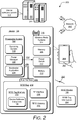
- FIG. 2 further illustrates an example system 200 with a device 104 as described with reference to FIG. 1 , and in which embodiments of RFID-based device wireless updates can be implemented.
- the example device 104 may be any type of computing and/or electronic device, such as a mobile phone 202, tablet device, digital camera, or other types of consumer electronics, appliances, computers, and the like.
- the device 104 can be implemented with various components, such as a processing system 204 ( e . g ., one or more processors), a memory 206, an integrated display device 208, and any number and combination of various components as further described with reference to the example device shown in FIG. 6 .
- the device 104 includes a power source, such as a battery 210, to power the various device components.
- the device 104 also includes a power switch 212 that can be toggled to power-up or power-down the device.
- the device 104 can include the different wireless radio systems 214, such as for Wi-Fi, Bluetooth TM , Mobile Broadband, LTE, Near Field Communication (NFC), or any other wireless radio system or format for communication via respective wireless networks (e . g ., the wireless network 114 as described with reference to FIG. 1 ).
- the device 104 implements the wireless radio systems 214 that each include a radio device, antenna 216, and chipset that is implemented for cellular, wireless, and other network communication with other devices, networks, and services.
- a wireless radio system 214 can be configured to implement any suitable communication protocol or standard.
- the device 104 implements components and features of a radio-frequency identification (RFID) tag 218 that is implemented to store, in memory 220 of the RFID tag, at least the device software status information 108 as shown and described with reference to FIG. 1 .
- RFID radio-frequency identification
- any suitable non-volatile memory e . g ., the device memory 206 can be used to store the data and information that is associated with the device 104 separate from the RFID tag 218 and the RFID tag memory 220.
- the RFID tag 218 is also implemented for two-way wireless communication 222 with RFID readers, such as the RFID reader 106 (also referred to as a RFID interrogator) that interrogates the RFID tag 218 for the device software status information 108 that is stored in the RFID tag memory 220.
- RFID tags are small electronic tags or labels that can be programmed with data and other information.
- the RFID reader 106 can transmit an interrogation signal as a broadcast message requesting RFID tags that are in range to return the data and information that the RFID tags have stored.
- the RFID tags can then wirelessly communicate the data and information to the RFID reader via a radio frequency (RF) communication channel, which the RFID reader 106 receives as the RFID tag information 224.
- RF radio frequency
- a RFID tag (e . g ., the RFID tag 218) can include an ASIC / CPU module, a communication bus for communicating with the processing system 204 of the device 104, an RFID antenna 226, and a transmitter and receiver (or may be implemented as a transceiver) for two-way communication with the RFID reader 106.
- the ASIC / CPU module of the RFID tag 218 formulates a response that may include data from the RFID tag, and the response is wirelessly transmitted to the RFID reader.
- the response signals from a RFID tag 218 can be communicated using low frequency (LF), high frequency (HF), or ultra-high frequency (UHF) radio waves.
- the RFID tag data can be stored in non-volatile memory, and the ASIC / CPU module can be implemented as fixed or programmable logic for processing the RFID tag data, as well as modulating and demodulating the RF signals.
- the processing system 204 includes an operating system 228 of the device 104, and a power manager 230 that controls and toggles an interrupt enable line 232 connected to the power switch 212.
- the device can then be powered-down remotely while still in the packaging. Further, the device 104 can be powered-up to download the device software update 122 and then initiated to power-down utilizing the interrupt enable line 232.
- the processing system 204 also includes a bootloader application 234 to implement embodiments of RFID-based device wireless updates.
- the bootloader application 234 can be implemented as a software application or module, such as computer-executable software instructions that are executable with a processor ( e . g ., with the processing system 204).
- the operating system 228, the power manager 230, and the bootloader application 234 can be stored on computer-readable storage memory ( e . g ., the device memory 206), such as any suitable memory device or electronic data storage implemented in the device. Further, although shown and described as separate components, the power manager 230 and/or the bootloader application 234 may be implemented as a module or component of the operating system 228.
- the processing system 204, to include the operating system 228, the power manager 230, and/or the bootloader application 234 can communicate with the RFID tag 218 via a communication bus 236 that is implemented in the device 104.
- the RFID tag memory 220 e .
- non-volatile memory can be accessed by the RFID reader 106 via a radio frequency (RF) interface 238 of the RFID tag 218, or can be accessed via a bus interface 240 that connects the communication bus 236 to the RFID tag.
- the processing system 204 can communicate with the RFID tag 218 via the communication bus 236 and the bus interface 240 when the device 104 is powered-on.
- the interrupt enable line 232 is connected to the power switch 212 of the device 104, and the power switch can be turned on and off via an output signal from the RFID tag 218, via the bus interface 240 and the communication bus 236 to the power manager 230.
- the device 104 can be wirelessly powered-up ( e . g ., turned-on) or powered-down ( e . g ., turned off) by a command sent from the external RFID reader 106 to the RFID tag 218, which then communicates the command to the power manager 230 that toggles the interrupt enable line 232 connected to the power switch 212.
- the device 104 can also be powered-down remotely while still in the packaging.
- the RFID reader 106 can be used to interrogate the RFID tag 218 in the device 104, notably while the device is still packaged for shipment and/or retail, to determine whether the device needs a firmware or software update, such as an update of the operating system 228.
- the RFID reader can receive a response of the device identifier 110 and the software version indicator 112 from the device 104, as stored in the RFID tag memory 220.
- the RFID reader 106 can then communicate, via a network 242 (e . g ., a Wi-Fi network), with a server device 244 to determine whether the device software for the device 104 is the latest version of the device software.
- a network 242 e . g ., a Wi-Fi network
- the RFID reader 106 can communicate the device identifier 110 and the software version indicator 112 for the device 104 to the server device 244, which then compares the information with similar stored information about the device to assess whether the particular device has the latest version of device software.
- the server device 244 can communicate the device information back to the RFID reader 106, which then determines whether the particular device has the latest version of device software.
- the example system 200 includes the network 242 that generally represents any type of communication and data network, and any of the server and user devices described herein can communicate via the network 242 (or combination of networks), such as for data communication between the device 104 and the server device 244.
- the network 242 can be implemented to include wired and/or wireless networks (e .g ., to include the wireless network 114).
- the network can also be implemented using any type of network topology and/or communication protocol, and can be represented or otherwise implemented as a combination of two or more networks, to include cellular networks, IP-based networks, and/or the Internet.
- the network 242 may also include mobile operator networks that are managed by a network provider of a cellular network, a mobile network operator, and/or other network operators, such as a communication service provider, mobile phone provider, and/or Internet service provider.
- the RFID reader 106 can communicate the file location of the device software update 122 to the RFID tag 218 in the device 104, and the software update file location 118 is stored in the RFID tag memory 220.
- the file location 118 of the device software update 122 is a universal resource locator (URL) to the server device 244 that maintains the device software update for the device 104 that does not have the latest version of device software.
- URL universal resource locator
- the RFID reader 106 can communicate wireless network connection information to the RFID tag 218 of the device 104, and the wireless network connection information that is associated with the network 242 is stored in the RFID tag memory 220 as the wireless network and key 124.
- the wireless network connection information includes an identification of the network 242 and the network credentials (e.g., the network key) to join the wireless network for wireless communication.
- the RFID reader 106 can also communicate an update indicator to the RFID tag 218 of the device 104 and the update indicator is set in the RFID tag memory 220 as the update enable flag 126, which then serves as a software update indication for the bootloader application 234 of the device 104 when the device is powered-up.
- the device software update 122 can be communicated to the RFID reader 106, such as for a smaller-sized software patch, or for a new file for direct download to the RFID tag 218 of the device 104.
- the update can then be pushed directly from the RFID reader 106 to the RFID tag memory 220 of the embedded RFID tag 218 in the device.
- the RFID reader 106 communicates a power-up command to the RFID tag 218 of the device 104 and the power-up command is set in the RFID tag memory 220 as the interrupt enable 128, which is effective to initiate the RFID tag 218 enabling the interrupt enable line 232 via the power manager 230 to power the device on, initiating the device to download the device software update 122 from the file location utilizing the wireless network connection information.
- the interrupt enable 128 is set in the RFID tag memory 220 of the device 104
- the device powers-up and the bootloader application 234 is executed on the device.
- the bootloader application reads the update enable flag 126 stored in the RFID tag memory 220, which indicates to the bootloader application that the device software update 122 for the device software is available.
- the bootloader application 234 obtains the wireless network and key 124 (e.g., the wireless network connection information) that is stored in the RFID tag memory 220, and configures a wireless radio system 214 (e.g., Wi-Fi system) of the device for communication via the network 242.
- the bootloader application 234 also obtains the software update file location 118 from the RFID tag memory 220, and in this example, communicates with the server device 244 to download the device software update 122 from the file location via the network 242.
- the bootloader application 234 obtains the device software update that is stored locally in the RFID tag memory 220.
- the device software update 122 can then be stored in the device memory 206 and the device powered-down with the device software update available from the device memory when the device is subsequently powered on, such as when the device is purchased, opened from the packaging by a consumer, and powered on.
- the device software update 122 can then be applied to update the device software, the software version indicator 112 in the RFID tag memory 220 updated to reflect the now current version of the device software, and an update pass or fail flag 130 can be set accordingly.
- the bootloader application 234 can download and store the device software update 122, as well as perform updating the device software with the device software update before the device is powered off.
- the bootloader application 234 can also update the software version indicator 112 in the RFID tag memory, set the update pass or fail flag 130 accordingly, and then initiate powering-down the device.
- Example methods 300, 400, and 500 are described with reference to respective FIGs. 3 , 4 , and 5 in accordance with implementations of RFID-based device wireless updates.
- any services, components, modules, methods, and/or operations described herein can be implemented using software, firmware, hardware ( e.g ., fixed logic circuitry), manual processing, or any combination thereof.
- Some operations of the example methods may be described in the general context of executable instructions stored on computer-readable storage memory that is local and/or remote to a computer processing system, and implementations can include software applications, programs, functions, and the like.
- any of the functionality described herein can be performed, at least in part, by one or more hardware logic components, such as, and without limitation, Field-programmable Gate Arrays (FPGAs), Application-specific Integrated Circuits (ASICs), Application-specific Standard Products (ASSPs), System-on-a-chip systems (SoCs), Complex Programmable Logic Devices (CPLDs), and the like.
- FPGAs Field-programmable Gate Arrays
- ASICs Application-specific Integrated Circuits
- ASSPs Application-specific Standard Products
- SoCs System-on-a-chip systems
- CPLDs Complex Programmable Logic Devices
- FIG. 3 illustrates example method(s) 300 of RFID-based device wireless updates as described herein, and is generally described with reference to the RFID reader 106.
- the order in which the method is described is not intended to be construed as a limitation, and any number or combination of the described method operations can be performed in any order to perform a method, or an alternate method.
- a radio-frequency identification (RFID) tag of a device is interrogated with a RFID reader.
- the RFID reader 106 interrogates the RFID tag 218 in the device 104 to determine whether the device needs a firmware or software update, such as an update of the operating system 228.
- the RFID reader 106 interrogates the device 104 while the device is still packaged for shipment and/or retail, and while the device is powered off.
- a software version indicator is received from the RFID tag of the device.
- the RFID reader 106 receives a response of the device identifier 110 and the software version indicator 112 from the device 104, as stored in the RFID tag memory 220.
- the RFID reader 106 determines that the device software is not a latest version based on the response of the software version indicator 112 from the RFID tag 218.
- the RFID reader 106 communicates the device identifier 110 and the software version indicator 112 for the device 104 to the server device 244, which then compares the information with similar stored information about the device to assess whether the particular device has the latest version of device software.
- the server device 244 communicates the device information back to the RFID reader 106, which then determines whether the device 104 has the latest version of device software.
- wireless network connection information is communicated to the RFID tag of the device.
- the RFID reader 106 communicates wireless network connection information to the RFID tag 218 of the device 104, and the wireless network connection information that is associated with the network 242 is stored in the RFID tag memory 220 as the wireless network and key 124.
- the wireless network connection information includes an identification of the network 242 and the network credentials (e.g., the network key) to join the wireless network for wireless communication.
- a file location of a device software update is communicated to the RFID tag of the device.
- the RFID reader 106 communicates the file location of the device software update 122 to the RFID tag 218 in the device 104, and the software update file location 118 is stored in the RFID tag memory 220.
- the file location 118 of the device software update 122 is a universal resource locator (URL) to the server device 244 that maintains the device software update for the device 104 that does not have the latest version of device software.
- URL universal resource locator
- an update indicator is communicated to the RFID tag of the device effective to set an update enable flag in the memory of the RFID tag.
- the RFID reader 106 communicates an update indicator to the RFID tag 218 of the device 104 and the update indicator is set in the RFID tag memory 220 as the update enable flag 126, which then serves as a software update indication for the bootloader application 234 of the device 104 when the device is powered-up.
- a power-up command is communicated to the RFID tag effective to initiate the RFID tag enabling an interrupt line to power the device on.
- the RFID reader 106 communicates a power-up command to the RFID tag 218 of the device 104 and the power-up command is set in the RFID tag memory 220 as the interrupt enable 128, which is effective to initiate the RFID tag 218 enabling the interrupt enable line 232 via the power manager 230 to power the device on, initiating the device 104 to download the device software update 122 from the file location utilizing the wireless network connection information.
- the interrupt enable 128 is set in the RFID tag memory 220 of the device 104, the device powers-up and the bootloader application 234 is executed on the device to download the device software update 122 from the file location utilizing the wireless network connection information.
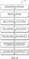
- FIG. 4 illustrates example method(s) 400 of RFID-based device wireless updates, and is generally described with reference to the device 104 that implements the RFID tag 218.
- the order in which the method is described is not intended to be construed as a limitation, and any number or combination of the described method operations can be performed in any order to perform a method, or an alternate method.
- an interrogation of a radio-frequency identification (RFID) tag is received from a RFID reader.
- the RFID tag 218 receives an interrogation from the RFID reader 106 to determine whether the device needs a firmware or software update, such as an update of the operating system 228.
- the RFID reader 106 can interrogate the device 104 while the device is still packaged for shipment and/or retail, and while the device is powered off.
- a software version indicator of the device software is the response.
- the RFID tag 218 responds to the RFID reader 106 with the device identifier 110 and the software version indicator 112, as stored in the RFID tag memory 220.
- an update indicator is received from the RFID reader to indicate that the device software is not a latest version and, at 408, an update enable flag is stored in memory of the RFID tag of the device responsive to receiving the update indicator.
- the RFID tag 218 receives an update indicator from the RFID reader 106 and the update indicator is set in the RFID tag memory 220 as the update enable flag 126, which then serves as a software update indication for the bootloader application 234 of the device 104 when the device is powered-up.
- wireless network connection information and a file location of a device software update is received from a RFID reader and, at 412, the wireless network connection information and the file location of the device software update is stored in the memory of the RFID tag of the device.
- the RFID tag 218 receives the wireless network connection information that is associated with the network 242 and stored in the RFID tag memory 220 as the wireless network and key 124, and the RFID tag 218 receives the file location of the device software update 122 from the RFID reader 106, and the software update file location 118 is stored in the RFID tag memory 220.
- the wireless network connection information includes an identification of the network 242 and the network credentials (e.g., the network key) to join the wireless network for wireless communication.
- the file location 118 of the device software update 122 can be a universal resource locator (URL) to the server device 244 that maintains the device software update for the device 104.
- URL universal resource locator
- a power-up command to the RFID tag is received from the RFID reader initiating powering-up the device based on a determination that the device software is not the latest version.
- the RFID tag 218 receives a power-up command from the RFID reader 106 that is set in the RFID tag memory 220 as the interrupt enable 128, which is effective to initiate the RFID tag 218 enabling the interrupt enable line 232 via the power manager 230 to power the device on, initiating the device 104 to download the device software update 122 from the file location utilizing the wireless network connection information.
- FIG. 5 illustrates example method(s) 500 of RFID-based device wireless updates, and is generally described with reference to the device 104 that implements the RFID tag 218.
- the order in which the method is described is not intended to be construed as a limitation, and any number or combination of the described method operations can be performed in any order to perform a method, or an alternate method.
- the device is powered-up when the RFID tag of the device enables an interrupt line to power the device on.
- the RFID tag 218 enables the interrupt enable line 232 via the power manager 230 to power the device 104 on.
- the interrupt enable 128 is set in the RFID tag memory 220 of the device 104, the device powers-up and the bootloader application 234 is executed on the device.
- the bootloader application 234 reads the update enable flag 126 stored in the RFID tag memory 220, which indicates to the bootloader application that the device software update 122 for the device software is available.
- the wireless network connection information stored in the memory of the RFID tag is obtained effective to configure a wireless radio system of the device for communication via the wireless network.
- the bootloader application 234 obtains the wireless network and key 124 (e.g., the wireless network connection information) that is stored in the RFID tag memory 220, and configures a wireless radio system 214 (e.g., Wi-Fi system) of the device for communication via the network 242.
- the file location of the device software update is obtained from the memory of the RFID tag and, at 510, the device software update stored on a server device is accessed via the wireless network based on the file location as a universal resource locator (URL) to the server device.
- the bootloader application 234 obtains the software update file location 118 from the RFID tag memory 220 and communicates with the server device 244 to download the device software update 122 from the file location via the network 242.
- the device software update is downloaded from the file location via the wireless network and, at 514, the device software update is stored in device memory.
- the bootloader application 234 initiates downloading the device software update 122 from the file location 118 at the server device 244 via the network 242, and the device software update 122 is stored in the device memory 206.
- the device software is updated with the device software update.
- the bootloader application 234 is executed to perform updating the device software with the device software update 122 before the device is powered off.
- the device is powered-down.
- the bootloader application 234 powers-down the device 104 with the device software update 122 available from the device memory 206 when the device is subsequently powered on.
- FIG. 6 illustrates various components of an example device 600 in which embodiments of RFID-based device wireless updates can be implemented.
- the example device 600 can be implemented as any of the devices described with reference to the previous FIGS. 1-5 , such as any type of client device, mobile phone, tablet, computing, communication, entertainment, gaming, media playback, and/or other type of electronic device.
- the devices 104 shown in FIGs. 1 and 2 may be implemented as the example device 600.
- the device 600 includes communication transceivers 602 that enable wired and/or wireless communication of device data 604 with other devices, such as the device identifier 110, the software version indicator 112, and the other device software status information 108 as described with reference to the devices 104 shown in FIGs. 1 and 2 .
- the device data can include any type of audio, video, and/or image data.
- Example transceivers include wireless personal area network (WPAN) radios compliant with various IEEE 802.15 (Bluetooth TM ) standards, wireless local area network (WLAN) radios compliant with any of the various IEEE 802.11 (WiFi TM ) standards, wireless wide area network (WWAN) radios for cellular phone communication, wireless metropolitan area network (WMAN) radios compliant with various IEEE 802.15 (WiMAX TM ) standards, and wired local area network (LAN) Ethernet transceivers for network data communication.
- WPAN wireless personal area network
- WLAN wireless local area network
- WiFi TM wireless wide area network
- WWAN wireless wide area network
- WMAN wireless metropolitan area network
- LAN wired local area network
- the device 600 may also include one or more data input ports 606 via which any type of data, media content, and/or inputs can be received, such as user-selectable inputs to the device, messages, music, television content, recorded content, and any other type of audio, video, and/or image data received from any content and/or data source.
- the data input ports may include USB ports, coaxial cable ports, and other serial or parallel connectors (including internal connectors) for flash memory, DVDs, CDs, and the like. These data input ports may be used to couple the device to any type of components, peripherals, or accessories such as microphones and/or cameras.
- the device 600 includes a processing system 608 of one or more processors (e . g ., any of microprocessors, controllers, and the like) and/or a processor and memory system implemented as a system-on-chip (SoC) that processes computer-executable instructions.
- the processor system may be implemented at least partially in hardware, which can include components of an integrated circuit or on-chip system, an application-specific integrated circuit (ASIC), a field-programmable gate array (FPGA), a complex programmable logic device (CPLD), and other implementations in silicon and/or other hardware.
- the device can be implemented with any one or combination of software, hardware, firmware, or fixed logic circuitry that is implemented in connection with processing and control circuits, which are generally identified at 610.
- the device 600 may further include any type of a system bus or other data and command transfer system that couples the various components within the device.
- a system bus can include any one or combination of different bus structures and architectures, as well as control and data lines.
- the device 600 also includes computer-readable storage memory 612 that enable data storage, such as data storage devices that can be accessed by a computing device, and that provide persistent storage of data and executable instructions (e . g ., software applications, programs, functions, and the like). Examples of the computer-readable storage memory 612 include volatile memory and non-volatile memory, fixed and removable media devices, and any suitable memory device or electronic data storage that maintains data for computing device access.
- the computer-readable storage memory can include various implementations of random access memory (RAM), read-only memory (ROM), flash memory, and other types of storage media in various memory device configurations.
- the device 600 may also include a mass storage media device.
- the computer-readable storage memory 612 provides data storage mechanisms to store the device data 604, other types of information and/or data, and various device applications 614 (e . g ., software applications).
- an operating system 616 can be maintained as software instructions with a memory device and executed by the processing system 608.
- the device applications may also include a device manager, such as any form of a control application, software application, signalprocessing and control module, code that is native to a particular device, a hardware abstraction layer for a particular device, and so on.
- the device 600 includes a bootloader application 618 that implements embodiments of RFID-based device wireless updates, and may be implemented with hardware components and/or in software, such as when the device 600 is implemented as the device 104 described with reference to FIGS. 1-5 .
- An example of the bootloader application 618 is the bootloader application 234 that is implemented as an application in the device 104.
- the device 600 also includes a radio-frequency identification (RFID) tag 620, such as described with reference to the RFID tag 218 implemented in the device 104.
- RFID radio-frequency identification
- the device 600 can also include one or more device sensors 622, such as any one or more of an ambient light sensor, a proximity sensor, a touch sensor, an infrared (IR) sensor, and the like from which a stowed context of the device can be determined.
- the device 600 can also include one or more power sources 624, such as when the device is implemented as a mobile device.
- the power sources may include a charging and/or power system, and can be implemented as a flexible strip battery, a rechargeable battery, a charged super-capacitor, and/or any other type of active or passive power source.
- the device 600 also includes an audio and/or video processing system 626 that generates audio data for an audio system 628 and/or generates display data for a display system 630.
- the audio system and/or the display system may include any devices that process, display, and/or otherwise render audio, video, display, and/or image data.
- Display data and audio signals can be communicated to an audio component and/or to a display component via an RF (radio frequency) link, S-video link, HDMI (high-definition multimedia interface), composite video link, component video link, DVI (digital video interface), analog audio connection, or other similar communication link, such as media data port 632.
- the audio system and/or the display system are integrated components of the example device.
- the audio system and/or the display system are external, peripheral components to the example device.
Landscapes
- Engineering & Computer Science (AREA)
- Theoretical Computer Science (AREA)
- General Engineering & Computer Science (AREA)
- Physics & Mathematics (AREA)
- Software Systems (AREA)
- General Physics & Mathematics (AREA)
- Databases & Information Systems (AREA)
- Computer Security & Cryptography (AREA)
- Toxicology (AREA)
- Health & Medical Sciences (AREA)
- Data Mining & Analysis (AREA)
- Computer Vision & Pattern Recognition (AREA)
- Artificial Intelligence (AREA)
- General Health & Medical Sciences (AREA)
- Electromagnetism (AREA)
- Signal Processing (AREA)
- Computer Networks & Wireless Communication (AREA)
- Stored Programmes (AREA)
- Information Transfer Between Computers (AREA)
Abstract
Description
- Portable devices, such as mobile phones, tablet devices, digital cameras, and other types of computing and electronic devices are manufactured and then packaged for shipment and retail sales. Typically, the devices are manufactured and packaged with a current firmware and/or software image, such as the operating system of a device. However, by the time the devices are packaged and shipped to a distributor for retail sales, the initial firmware and/or software may be out-of-date, or may not be the latest version for a particular device. This can cause an unfavorable user experience and customer dissatisfaction when having to first update the firmware and/or software for a newly purchased device. This need to update the software and/or firmware of devices in existing inventory is overly expensive and results in lost revenue, given that the devices need to be removed from the packaging and then re-packaged, in addition to the labor, time, and infrastructure needed to facilitate updating the devices.
- Embodiments of RFID-based device wireless updates are described with reference to the following Figures. The same numbers may be used throughout to reference like features and components that are shown in the Figures:
-
FIG. 1 illustrates an example system in which embodiments of RFID-based device wireless updates can be implemented. -
FIG. 2 further illustrates an example system in which embodiments of RFID-based device wireless updates can be implemented. -
FIG. 3 illustrates example method(s) of RFID-based device wireless updates in accordance with one or more embodiments. -
FIG. 4 illustrates example method(s) of RFID-based device wireless updates in accordance with one or more embodiments. -
FIG. 5 illustrates example method(s) of RFID-based device wireless updates in accordance with one or more embodiments. -
FIG. 6 illustrates various components of an example device that can implement embodiments of RFID-based device wireless updates. - Embodiments of RFID-based device wireless updates are described, such as for any type of computing, mobile, and/or electronic device that may be implemented with a radio-frequency identification (RFID) tag that can be utilized to update the device firmware and/or software over-the-air (e.g., via a wireless network). Further, even while a device is still packaged in shipping or retail packaging, a RFID tag can be utilized to determine whether the device firmware and/or software, such as an operating system of the device, is the latest version, or whether the device firmware or software needs to be updated. As noted above, devices are generally manufactured with a current firmware and/or software image, such as the operating system of a device. However, by the time the devices are packaged and shipped to a distributor, the initial firmware and/or software may be out-of-date, or may not be the latest version for a particular device. Rather than having to open the packaging of each device, or selling a device to a consumer with out-of-date software, embodiments of RFID-based device wireless updates can be implemented to update the device firmware and/or software, even for devices that are still in shipping and/or retail packaging, either at a manufacturing facility, in-transit, or stored at a distribution or retail site.
- A mobile phone device, for example, can include a RFID tag that is implemented to share encrypted information about the device software, and can decrypt and update the device software and/or firmware over-the-air (e.g., via wireless communication). The RFID tag hardware provides a communication bus to read secure data that a processor of the mobile device can read, and also provides an interrupt line connected to a power manager integrated circuit (PMIC) of the mobile device to allow booting of the device from a dormant state. The described system can be used in manufacturing, distribution, and service centers, as well as may be implemented as a kiosk from which a user can update device firmware and software in a device.
- In aspects of RFID-based device wireless updates, a RFID reader can be used to interrogate a RFID tag of a device, and receive a response of a software version indicator that indicates device software on the device is not a latest version. The RFID reader communicates wireless network connection information and a file location of a device software update to the RFID tag of the device. The RFID tag includes memory to maintain the file location and the wireless network connection information that is associated with a wireless network. The RFID reader can then communicate a power-up command to the RFID tag effective to initiate the RFID tag enabling an interrupt enable line to power the device on.
- A bootloader application executing on the device can determine from an update enable flag stored in the RFID tag memory that the device software update is available. The bootloader application can then obtain the wireless network connection information stored in the RFID tag memory effective to configure a wireless radio system of the device for communication via the wireless network. The bootloader application can also obtain the file location of the device software update from the RFID tag memory, and download the device software update from the file location via the wireless network. The device software update can then be stored in device memory and the device powered-down with the device software update available from the device memory when the device is subsequently powered on, such as when the device is purchased, opened from the packaging by a consumer, and powered on. Alternatively, the device software update can be downloaded and stored in device memory, and the update to the device software is completed before the device is powered off.
- In other aspects of RFID-based device wireless updates, the device software update can be available locally on the RFID reader, such as for a smaller-sized software patch, or for a new file for direct download to the RFID tag of the device. The update can then be pushed directly from the RFID reader to the RFID tag memory of the embedded RFID tag, and the RFID reader communicates the power-up command to the RFID tag of the device. In this instance, the file location of the software update that is stored in the RFID tag memory indicates that the device software update is stored locally in the RFID tag memory, and the bootloader application of the device can access the software update from the RFID tag memory when the device is powered-up.
- As used herein, the term "powered on" indicates that a device is on and in an operational state, and the term "powered off" indicates that the device is off. The term "powered-up" is used to indicate that a device is in the process of turning-on, such as when a user of the device presses the power switch to turn the device on, or when the power switch is toggled to turn the device on. After the device has "powered-up" from the "powered off" state, the device is then in the "powered on" state. The term "powered-down" is used to indicate that a device is in the process of turning-off, such as when the user of the device presses the power switch to turn the device off, or when the power switch is toggled to turn the device off. After the device has "powered-down" from the "powered on" state, the device is then in the "powered off" state.
- While features and concepts of RFID-based device wireless updates can be implemented in any number of different devices, systems, environments, and/or configurations, embodiments of RFID-based device wireless updates are described in the context of the following example devices, systems, and methods.
-
FIG. 1 illustrates anexample system 100 in which embodiments of RFID-based device wireless updates can be implemented. The example system includes arepresentation 102 ofmultiple devices 104, such as devices packaged in shipping and/or retail packaging, either at a manufacturing facility, in-transit, or stored at a distribution or retail site. Thedevices 104 may be any type of mobile phone, tablet device, computing device (e.g., portable and desktop computers), consumer electronic device (e.g., television, appliance, and the like), or other types of computing and electronic devices that are typically battery powered or may have a small coin cell battery used to boot a device bios or bootloader application. As noted above, thedevices 104 are generally manufactured with a current firmware and/or software image, such as the operating system of a device. However, by the time the devices are packaged and shipped to a distributor, the initial firmware and/or software may be out-of-date, or may not be the latest version for a particular device. - A radio-frequency identification (RFID)
reader 106 can be used to interrogate a RFID tag in each of thedevices 104, notably while the devices remain packaged, to determine whether one or more of the devices are in need of a firmware or software update. Although the examples and discussion herein refer mainly to device software and whether the device software is up-to-date or is the latest version of the device software, the techniques described herein may be similarly implemented for any type of device firmware. In this example, each of thedevices 104 maintain devicesoftware status information 108, such as data stored in a memory of the RFID tag in each respective device. In response to theRFID reader 106 interrogating thedevices 104, the RFID reader can receive a response of adevice identifier 110 and asoftware version indicator 112 from each of the respective devices. - The
RFID reader 106 can then communicate, via a wireless network 114 (e.g., a Wi-Fi network), with aserver device 116 to determine whether the device software for each of thedevices 104 is or is not the latest version of the device software. For example, theRFID reader 106 can communicate thedevice identifier 110 and thesoftware version indicator 112 for one of thedevices 104 to theserver device 116, which then compares the information with similar stored information about the device to assess whether the particular device has the latest version of device software. Alternatively, theserver device 116 can communicate the device information back to theRFID reader 106, which then determines whether the particular device has the latest version of device software. - In the event that the
device 104 does not have the latest version of device software, as determined at theserver device 116 and/or at theRFID reader 106, theRFID reader 106 can communicate a file location of a device software update to the RFID tag in the device, and the softwareupdate file location 118 is stored in the RFID tag memory. In implementations, thefile location 118 of a device software update is a universal resource locator (URL) to aserver device 120 that maintains thedevice software update 122 for theparticular device 104 that does not have the latest version of device software. Although shown and described as separate server devices, theserver device 116 that assesses whether thedevice 104 has the latest version of the device software, and theserver device 120 that maintains thedevice software update 122, can be implemented together as one server device, or alternatively, may be implemented as multiple server devices. - Additionally, the
RFID reader 106 can communicate wireless network connection information to the RFID tag of the device, and the wireless network connection information that is associated with thewireless network 114 is stored in the RFID tag memory as the wireless network andkey 124. The wireless network connection information includes an identification of thewireless network 114 and the network credentials (e.g., the network key) to join the wireless network for wireless communication. TheRFID reader 106 can also communicate an update indicator to the RFID tag of thedevice 104 and the update indicator is set in the RFID tag memory as an update enableflag 126, which then serves as a software update indication for a bootloader application of thedevice 104 when the device is powered-up. Further, theRFID reader 106 communicates a power-up command to the RFID tag of thedevice 104 and the power-up command is set in the RFID tag memory as an interrupt enable 128, which is effective to initiate the RFID tag enabling an interrupt line to power the device on, initiating the device to download the device software update from the file location utilizing the wireless network connection information. - Alternatively, the
server device 120 can communicate thedevice software update 122 to theRFID reader 106, such as for a smaller-sized software patch, or for a new file for direct download to the RFID tag of the device. The update can then be pushed directly from the RFID reader to the RFID tag memory of the embedded RFID tag, and theRFID reader 106 communicates the power-up command to the RFID tag as the interrupt enable 128. In this instance, the softwareupdate file location 118 that is stored in the RFID tag memory indicates that thedevice software update 122 is stored locally in the RFID tag memory, and the wireless network connection information that is associated with thewireless network 114 would not be needed by the bootloader application of thedevice 104 when the device is powered-up. - When the interrupt enable 128 is set in the RFID tag memory of the
device 104, the device powers-up and a bootloader application is executed on the device. The bootloader application reads the update enableflag 126 stored in the RFID tag memory, which indicates to the bootloader application that thedevice software update 122 for the device software is available. The bootloader application can obtain the wireless network and key 124 (e.g., the wireless network connection information) that is stored in the RFID tag memory, and configures a wireless radio system (e.g., Wi-Fi system) of the device for communication via thewireless network 114. The bootloader application also obtains the softwareupdate file location 118 from the RFID tag memory, and in the first example, communicates with theserver device 120 to download thedevice software update 122 from the file location via thewireless network 114. Alternatively, the bootloader application reads the update enableflag 126 stored in the RFID tag memory and, in the case of the software update being stored locally in the RFID tag memory of the RFID tag, the bootloader application reads thedevice software update 122 from the RFID tag memory. - The
device software update 122 can then be stored in device memory (e.g., when downloaded from theserver device 120 or read from the RFID tag memory) and the device powered-down with the device software update available from the device memory when the device is subsequently powered on, such as when the device is purchased, opened from the packaging by a consumer, and powered on. Thedevice software update 122 can then be applied to update the device software, thesoftware version indicator 112 in the RFID tag memory updated to reflect the now current version of the device software, and an update pass or failflag 130 can be set accordingly. As an alternative to just downloading and storing thedevice software update 122, and then powering-down thedevice 104, the bootloader application can download and store thedevice software update 122, as well as perform updating the device software with the device software update before the device is powered off. The bootloader application can also update thesoftware version indicator 112 in the RFID tag memory, set the update pass or failflag 130 accordingly, and then initiate powering-down the device. -
FIG. 2 further illustrates anexample system 200 with adevice 104 as described with reference toFIG. 1 , and in which embodiments of RFID-based device wireless updates can be implemented. As noted above, theexample device 104 may be any type of computing and/or electronic device, such as amobile phone 202, tablet device, digital camera, or other types of consumer electronics, appliances, computers, and the like. Thedevice 104 can be implemented with various components, such as a processing system 204 (e.g., one or more processors), amemory 206, anintegrated display device 208, and any number and combination of various components as further described with reference to the example device shown inFIG. 6 . Additionally, thedevice 104 includes a power source, such as abattery 210, to power the various device components. Thedevice 104 also includes apower switch 212 that can be toggled to power-up or power-down the device. - Further, the
device 104 can include the differentwireless radio systems 214, such as for Wi-Fi, Bluetooth™, Mobile Broadband, LTE, Near Field Communication (NFC), or any other wireless radio system or format for communication via respective wireless networks (e.g., thewireless network 114 as described with reference toFIG. 1 ). Generally, thedevice 104 implements thewireless radio systems 214 that each include a radio device,antenna 216, and chipset that is implemented for cellular, wireless, and other network communication with other devices, networks, and services. Awireless radio system 214 can be configured to implement any suitable communication protocol or standard. - In this example, the
device 104 implements components and features of a radio-frequency identification (RFID)tag 218 that is implemented to store, inmemory 220 of the RFID tag, at least the devicesoftware status information 108 as shown and described with reference toFIG. 1 . Alternatively, any suitable non-volatile memory (e.g., the device memory 206) can be used to store the data and information that is associated with thedevice 104 separate from theRFID tag 218 and theRFID tag memory 220. TheRFID tag 218 is also implemented for two-way wireless communication 222 with RFID readers, such as the RFID reader 106 (also referred to as a RFID interrogator) that interrogates theRFID tag 218 for the devicesoftware status information 108 that is stored in theRFID tag memory 220. Generally, RFID tags are small electronic tags or labels that can be programmed with data and other information. TheRFID reader 106 can transmit an interrogation signal as a broadcast message requesting RFID tags that are in range to return the data and information that the RFID tags have stored. The RFID tags can then wirelessly communicate the data and information to the RFID reader via a radio frequency (RF) communication channel, which theRFID reader 106 receives as theRFID tag information 224. - In implementations, a RFID tag (e.g., the RFID tag 218) can include an ASIC / CPU module, a communication bus for communicating with the
processing system 204 of thedevice 104, anRFID antenna 226, and a transmitter and receiver (or may be implemented as a transceiver) for two-way communication with theRFID reader 106. In response to receipt of an interrogation signal, the ASIC / CPU module of theRFID tag 218 formulates a response that may include data from the RFID tag, and the response is wirelessly transmitted to the RFID reader. The response signals from aRFID tag 218 can be communicated using low frequency (LF), high frequency (HF), or ultra-high frequency (UHF) radio waves. The RFID tag data can be stored in non-volatile memory, and the ASIC / CPU module can be implemented as fixed or programmable logic for processing the RFID tag data, as well as modulating and demodulating the RF signals. - In this example, the
processing system 204 includes anoperating system 228 of thedevice 104, and apower manager 230 that controls and toggles an interrupt enableline 232 connected to thepower switch 212. In an event that thedevice 104 has been stowed, but inadvertently powered on, the device can then be powered-down remotely while still in the packaging. Further, thedevice 104 can be powered-up to download thedevice software update 122 and then initiated to power-down utilizing the interrupt enableline 232. Theprocessing system 204 also includes abootloader application 234 to implement embodiments of RFID-based device wireless updates. Thebootloader application 234 can be implemented as a software application or module, such as computer-executable software instructions that are executable with a processor (e.g., with the processing system 204). - As software applications, the
operating system 228, thepower manager 230, and thebootloader application 234 can be stored on computer-readable storage memory (e.g., the device memory 206), such as any suitable memory device or electronic data storage implemented in the device. Further, although shown and described as separate components, thepower manager 230 and/or thebootloader application 234 may be implemented as a module or component of theoperating system 228. In implementations, theprocessing system 204, to include theoperating system 228, thepower manager 230, and/or thebootloader application 234 can communicate with theRFID tag 218 via acommunication bus 236 that is implemented in thedevice 104. In implementations, the RFID tag memory 220 (e.g., non-volatile memory) can be accessed by theRFID reader 106 via a radio frequency (RF)interface 238 of theRFID tag 218, or can be accessed via a bus interface 240 that connects thecommunication bus 236 to the RFID tag. Theprocessing system 204 can communicate with theRFID tag 218 via thecommunication bus 236 and the bus interface 240 when thedevice 104 is powered-on. - In this example, the interrupt enable
line 232 is connected to thepower switch 212 of thedevice 104, and the power switch can be turned on and off via an output signal from theRFID tag 218, via the bus interface 240 and thecommunication bus 236 to thepower manager 230. As noted above, thedevice 104 can be wirelessly powered-up (e.g., turned-on) or powered-down (e.g., turned off) by a command sent from theexternal RFID reader 106 to theRFID tag 218, which then communicates the command to thepower manager 230 that toggles the interrupt enableline 232 connected to thepower switch 212. Thedevice 104 can also be powered-down remotely while still in the packaging. - As described with reference to
FIG. 1 , theRFID reader 106 can be used to interrogate theRFID tag 218 in thedevice 104, notably while the device is still packaged for shipment and/or retail, to determine whether the device needs a firmware or software update, such as an update of theoperating system 228. In response to the interrogation from theRFID reader 106, the RFID reader can receive a response of thedevice identifier 110 and thesoftware version indicator 112 from thedevice 104, as stored in theRFID tag memory 220. TheRFID reader 106 can then communicate, via a network 242 (e.g., a Wi-Fi network), with aserver device 244 to determine whether the device software for thedevice 104 is the latest version of the device software. For example, theRFID reader 106 can communicate thedevice identifier 110 and thesoftware version indicator 112 for thedevice 104 to theserver device 244, which then compares the information with similar stored information about the device to assess whether the particular device has the latest version of device software. Alternatively, theserver device 244 can communicate the device information back to theRFID reader 106, which then determines whether the particular device has the latest version of device software. - The
example system 200 includes thenetwork 242 that generally represents any type of communication and data network, and any of the server and user devices described herein can communicate via the network 242 (or combination of networks), such as for data communication between thedevice 104 and theserver device 244. Thenetwork 242 can be implemented to include wired and/or wireless networks (e.g., to include the wireless network 114). The network can also be implemented using any type of network topology and/or communication protocol, and can be represented or otherwise implemented as a combination of two or more networks, to include cellular networks, IP-based networks, and/or the Internet. Thenetwork 242 may also include mobile operator networks that are managed by a network provider of a cellular network, a mobile network operator, and/or other network operators, such as a communication service provider, mobile phone provider, and/or Internet service provider. - In the event that the
device 104 does not have the latest version of device software, as determined at theserver device 244 and/or at theRFID reader 106, theRFID reader 106 can communicate the file location of thedevice software update 122 to theRFID tag 218 in thedevice 104, and the softwareupdate file location 118 is stored in theRFID tag memory 220. In implementations, thefile location 118 of thedevice software update 122 is a universal resource locator (URL) to theserver device 244 that maintains the device software update for thedevice 104 that does not have the latest version of device software. Additionally, theRFID reader 106 can communicate wireless network connection information to theRFID tag 218 of thedevice 104, and the wireless network connection information that is associated with thenetwork 242 is stored in theRFID tag memory 220 as the wireless network andkey 124. The wireless network connection information includes an identification of thenetwork 242 and the network credentials (e.g., the network key) to join the wireless network for wireless communication. TheRFID reader 106 can also communicate an update indicator to theRFID tag 218 of thedevice 104 and the update indicator is set in theRFID tag memory 220 as the update enableflag 126, which then serves as a software update indication for thebootloader application 234 of thedevice 104 when the device is powered-up. As an alternative noted above, thedevice software update 122 can be communicated to theRFID reader 106, such as for a smaller-sized software patch, or for a new file for direct download to theRFID tag 218 of thedevice 104. The update can then be pushed directly from theRFID reader 106 to theRFID tag memory 220 of the embeddedRFID tag 218 in the device. - Further, the
RFID reader 106 communicates a power-up command to theRFID tag 218 of thedevice 104 and the power-up command is set in theRFID tag memory 220 as the interruptenable 128, which is effective to initiate theRFID tag 218 enabling the interrupt enableline 232 via thepower manager 230 to power the device on, initiating the device to download thedevice software update 122 from the file location utilizing the wireless network connection information. When the interruptenable 128 is set in theRFID tag memory 220 of thedevice 104, the device powers-up and thebootloader application 234 is executed on the device. The bootloader application reads the update enableflag 126 stored in theRFID tag memory 220, which indicates to the bootloader application that thedevice software update 122 for the device software is available. Thebootloader application 234 obtains the wireless network and key 124 (e.g., the wireless network connection information) that is stored in theRFID tag memory 220, and configures a wireless radio system 214 (e.g., Wi-Fi system) of the device for communication via thenetwork 242. Thebootloader application 234 also obtains the softwareupdate file location 118 from theRFID tag memory 220, and in this example, communicates with theserver device 244 to download thedevice software update 122 from the file location via thenetwork 242. Alternatively, thebootloader application 234 obtains the device software update that is stored locally in theRFID tag memory 220. - The
device software update 122 can then be stored in thedevice memory 206 and the device powered-down with the device software update available from the device memory when the device is subsequently powered on, such as when the device is purchased, opened from the packaging by a consumer, and powered on. Thedevice software update 122 can then be applied to update the device software, thesoftware version indicator 112 in theRFID tag memory 220 updated to reflect the now current version of the device software, and an update pass or failflag 130 can be set accordingly. As an alternative to just downloading and storing thedevice software update 122, and then powering-down thedevice 104, thebootloader application 234 can download and store thedevice software update 122, as well as perform updating the device software with the device software update before the device is powered off. Thebootloader application 234 can also update thesoftware version indicator 112 in the RFID tag memory, set the update pass or failflag 130 accordingly, and then initiate powering-down the device. -
Example methods FIGs. 3 ,4 , and5 in accordance with implementations of RFID-based device wireless updates. Generally, any services, components, modules, methods, and/or operations described herein can be implemented using software, firmware, hardware (e.g., fixed logic circuitry), manual processing, or any combination thereof. Some operations of the example methods may be described in the general context of executable instructions stored on computer-readable storage memory that is local and/or remote to a computer processing system, and implementations can include software applications, programs, functions, and the like. Alternatively or in addition, any of the functionality described herein can be performed, at least in part, by one or more hardware logic components, such as, and without limitation, Field-programmable Gate Arrays (FPGAs), Application-specific Integrated Circuits (ASICs), Application-specific Standard Products (ASSPs), System-on-a-chip systems (SoCs), Complex Programmable Logic Devices (CPLDs), and the like. -
FIG. 3 illustrates example method(s) 300 of RFID-based device wireless updates as described herein, and is generally described with reference to theRFID reader 106. The order in which the method is described is not intended to be construed as a limitation, and any number or combination of the described method operations can be performed in any order to perform a method, or an alternate method. - At 302, a radio-frequency identification (RFID) tag of a device is interrogated with a RFID reader. For example, the
RFID reader 106 interrogates theRFID tag 218 in thedevice 104 to determine whether the device needs a firmware or software update, such as an update of theoperating system 228. Notably, theRFID reader 106 interrogates thedevice 104 while the device is still packaged for shipment and/or retail, and while the device is powered off. At 304, a software version indicator is received from the RFID tag of the device. For example, theRFID reader 106 receives a response of thedevice identifier 110 and thesoftware version indicator 112 from thedevice 104, as stored in theRFID tag memory 220. - At 306, a determination is made that device software is not a latest version based on the response of the software version indicator from the RFID tag. For example, the
RFID reader 106 determines that the device software is not a latest version based on the response of thesoftware version indicator 112 from theRFID tag 218. In implementations, theRFID reader 106 communicates thedevice identifier 110 and thesoftware version indicator 112 for thedevice 104 to theserver device 244, which then compares the information with similar stored information about the device to assess whether the particular device has the latest version of device software. Alternatively, theserver device 244 communicates the device information back to theRFID reader 106, which then determines whether thedevice 104 has the latest version of device software. - At 308, wireless network connection information is communicated to the RFID tag of the device. For example, the
RFID reader 106 communicates wireless network connection information to theRFID tag 218 of thedevice 104, and the wireless network connection information that is associated with thenetwork 242 is stored in theRFID tag memory 220 as the wireless network andkey 124. The wireless network connection information includes an identification of thenetwork 242 and the network credentials (e.g., the network key) to join the wireless network for wireless communication. - At 310, a file location of a device software update is communicated to the RFID tag of the device. For example, the
RFID reader 106 communicates the file location of thedevice software update 122 to theRFID tag 218 in thedevice 104, and the softwareupdate file location 118 is stored in theRFID tag memory 220. In implementations, thefile location 118 of thedevice software update 122 is a universal resource locator (URL) to theserver device 244 that maintains the device software update for thedevice 104 that does not have the latest version of device software. - At 312, an update indicator is communicated to the RFID tag of the device effective to set an update enable flag in the memory of the RFID tag. For example, the
RFID reader 106 communicates an update indicator to theRFID tag 218 of thedevice 104 and the update indicator is set in theRFID tag memory 220 as the update enableflag 126, which then serves as a software update indication for thebootloader application 234 of thedevice 104 when the device is powered-up. - At 314, a power-up command is communicated to the RFID tag effective to initiate the RFID tag enabling an interrupt line to power the device on. For example, the
RFID reader 106 communicates a power-up command to theRFID tag 218 of thedevice 104 and the power-up command is set in theRFID tag memory 220 as the interruptenable 128, which is effective to initiate theRFID tag 218 enabling the interrupt enableline 232 via thepower manager 230 to power the device on, initiating thedevice 104 to download thedevice software update 122 from the file location utilizing the wireless network connection information. When the interruptenable 128 is set in theRFID tag memory 220 of thedevice 104, the device powers-up and thebootloader application 234 is executed on the device to download thedevice software update 122 from the file location utilizing the wireless network connection information. -
FIG. 4 illustrates example method(s) 400 of RFID-based device wireless updates, and is generally described with reference to thedevice 104 that implements theRFID tag 218. The order in which the method is described is not intended to be construed as a limitation, and any number or combination of the described method operations can be performed in any order to perform a method, or an alternate method. - At 402, an interrogation of a radio-frequency identification (RFID) tag is received from a RFID reader. For example, the
RFID tag 218 receives an interrogation from theRFID reader 106 to determine whether the device needs a firmware or software update, such as an update of theoperating system 228. TheRFID reader 106 can interrogate thedevice 104 while the device is still packaged for shipment and/or retail, and while the device is powered off. At 404, a software version indicator of the device software is the response. For example, theRFID tag 218 responds to theRFID reader 106 with thedevice identifier 110 and thesoftware version indicator 112, as stored in theRFID tag memory 220. - At 406, an update indicator is received from the RFID reader to indicate that the device software is not a latest version and, at 408, an update enable flag is stored in memory of the RFID tag of the device responsive to receiving the update indicator. For example, the
RFID tag 218 receives an update indicator from theRFID reader 106 and the update indicator is set in theRFID tag memory 220 as the update enableflag 126, which then serves as a software update indication for thebootloader application 234 of thedevice 104 when the device is powered-up. - At 410, wireless network connection information and a file location of a device software update is received from a RFID reader and, at 412, the wireless network connection information and the file location of the device software update is stored in the memory of the RFID tag of the device. For example, the
RFID tag 218 receives the wireless network connection information that is associated with thenetwork 242 and stored in theRFID tag memory 220 as the wireless network and key 124, and theRFID tag 218 receives the file location of thedevice software update 122 from theRFID reader 106, and the softwareupdate file location 118 is stored in theRFID tag memory 220. The wireless network connection information includes an identification of thenetwork 242 and the network credentials (e.g., the network key) to join the wireless network for wireless communication. Thefile location 118 of thedevice software update 122 can be a universal resource locator (URL) to theserver device 244 that maintains the device software update for thedevice 104. - At 414, a power-up command to the RFID tag is received from the RFID reader initiating powering-up the device based on a determination that the device software is not the latest version. For example, the
RFID tag 218 receives a power-up command from theRFID reader 106 that is set in theRFID tag memory 220 as the interruptenable 128, which is effective to initiate theRFID tag 218 enabling the interrupt enableline 232 via thepower manager 230 to power the device on, initiating thedevice 104 to download thedevice software update 122 from the file location utilizing the wireless network connection information. -
FIG. 5 illustrates example method(s) 500 of RFID-based device wireless updates, and is generally described with reference to thedevice 104 that implements theRFID tag 218. The order in which the method is described is not intended to be construed as a limitation, and any number or combination of the described method operations can be performed in any order to perform a method, or an alternate method. - At 502, the device is powered-up when the RFID tag of the device enables an interrupt line to power the device on. For example, the
RFID tag 218 enables the interrupt enableline 232 via thepower manager 230 to power thedevice 104 on. When the interruptenable 128 is set in theRFID tag memory 220 of thedevice 104, the device powers-up and thebootloader application 234 is executed on the device. - At 504, a determination is made from the update enable flag stored in the memory of the RFID tag that a device software update to the device software is available. For example, the
bootloader application 234 reads the update enableflag 126 stored in theRFID tag memory 220, which indicates to the bootloader application that thedevice software update 122 for the device software is available. - At 506, the wireless network connection information stored in the memory of the RFID tag is obtained effective to configure a wireless radio system of the device for communication via the wireless network. For example, the
bootloader application 234 obtains the wireless network and key 124 (e.g., the wireless network connection information) that is stored in theRFID tag memory 220, and configures a wireless radio system 214 (e.g., Wi-Fi system) of the device for communication via thenetwork 242. - At 508, the file location of the device software update is obtained from the memory of the RFID tag and, at 510, the device software update stored on a server device is accessed via the wireless network based on the file location as a universal resource locator (URL) to the server device. For example, the
bootloader application 234 obtains the softwareupdate file location 118 from theRFID tag memory 220 and communicates with theserver device 244 to download thedevice software update 122 from the file location via thenetwork 242. - At 512, the device software update is downloaded from the file location via the wireless network and, at 514, the device software update is stored in device memory. For example, the
bootloader application 234 initiates downloading thedevice software update 122 from thefile location 118 at theserver device 244 via thenetwork 242, and thedevice software update 122 is stored in thedevice memory 206. - At 516, optionally, the device software is updated with the device software update. For example the
bootloader application 234 is executed to perform updating the device software with thedevice software update 122 before the device is powered off. At 518, the device is powered-down. For example, thebootloader application 234 powers-down thedevice 104 with thedevice software update 122 available from thedevice memory 206 when the device is subsequently powered on. -
FIG. 6 illustrates various components of anexample device 600 in which embodiments of RFID-based device wireless updates can be implemented. Theexample device 600 can be implemented as any of the devices described with reference to the previousFIGS. 1-5 , such as any type of client device, mobile phone, tablet, computing, communication, entertainment, gaming, media playback, and/or other type of electronic device. For example, thedevices 104 shown inFIGs. 1 and2 , as well as the server devices, may be implemented as theexample device 600. - The
device 600 includescommunication transceivers 602 that enable wired and/or wireless communication of device data 604 with other devices, such as thedevice identifier 110, thesoftware version indicator 112, and the other devicesoftware status information 108 as described with reference to thedevices 104 shown inFIGs. 1 and2 . Additionally, the device data can include any type of audio, video, and/or image data. Example transceivers include wireless personal area network (WPAN) radios compliant with various IEEE 802.15 (Bluetooth™) standards, wireless local area network (WLAN) radios compliant with any of the various IEEE 802.11 (WiFi™) standards, wireless wide area network (WWAN) radios for cellular phone communication, wireless metropolitan area network (WMAN) radios compliant with various IEEE 802.15 (WiMAX™) standards, and wired local area network (LAN) Ethernet transceivers for network data communication. - The
device 600 may also include one or moredata input ports 606 via which any type of data, media content, and/or inputs can be received, such as user-selectable inputs to the device, messages, music, television content, recorded content, and any other type of audio, video, and/or image data received from any content and/or data source. The data input ports may include USB ports, coaxial cable ports, and other serial or parallel connectors (including internal connectors) for flash memory, DVDs, CDs, and the like. These data input ports may be used to couple the device to any type of components, peripherals, or accessories such as microphones and/or cameras. - The
device 600 includes aprocessing system 608 of one or more processors (e.g., any of microprocessors, controllers, and the like) and/or a processor and memory system implemented as a system-on-chip (SoC) that processes computer-executable instructions. The processor system may be implemented at least partially in hardware, which can include components of an integrated circuit or on-chip system, an application-specific integrated circuit (ASIC), a field-programmable gate array (FPGA), a complex programmable logic device (CPLD), and other implementations in silicon and/or other hardware. Alternatively or in addition, the device can be implemented with any one or combination of software, hardware, firmware, or fixed logic circuitry that is implemented in connection with processing and control circuits, which are generally identified at 610. Thedevice 600 may further include any type of a system bus or other data and command transfer system that couples the various components within the device. A system bus can include any one or combination of different bus structures and architectures, as well as control and data lines. - The
device 600 also includes computer-readable storage memory 612 that enable data storage, such as data storage devices that can be accessed by a computing device, and that provide persistent storage of data and executable instructions (e.g., software applications, programs, functions, and the like). Examples of the computer-readable storage memory 612 include volatile memory and non-volatile memory, fixed and removable media devices, and any suitable memory device or electronic data storage that maintains data for computing device access. The computer-readable storage memory can include various implementations of random access memory (RAM), read-only memory (ROM), flash memory, and other types of storage media in various memory device configurations. Thedevice 600 may also include a mass storage media device. - The computer-
readable storage memory 612 provides data storage mechanisms to store the device data 604, other types of information and/or data, and various device applications 614 (e.g., software applications). For example, anoperating system 616 can be maintained as software instructions with a memory device and executed by theprocessing system 608. The device applications may also include a device manager, such as any form of a control application, software application, signalprocessing and control module, code that is native to a particular device, a hardware abstraction layer for a particular device, and so on. In this example, thedevice 600 includes abootloader application 618 that implements embodiments of RFID-based device wireless updates, and may be implemented with hardware components and/or in software, such as when thedevice 600 is implemented as thedevice 104 described with reference toFIGS. 1-5 . An example of thebootloader application 618 is thebootloader application 234 that is implemented as an application in thedevice 104. - The
device 600 also includes a radio-frequency identification (RFID)tag 620, such as described with reference to theRFID tag 218 implemented in thedevice 104. Thedevice 600 can also include one ormore device sensors 622, such as any one or more of an ambient light sensor, a proximity sensor, a touch sensor, an infrared (IR) sensor, and the like from which a stowed context of the device can be determined. Thedevice 600 can also include one ormore power sources 624, such as when the device is implemented as a mobile device. The power sources may include a charging and/or power system, and can be implemented as a flexible strip battery, a rechargeable battery, a charged super-capacitor, and/or any other type of active or passive power source. - The
device 600 also includes an audio and/orvideo processing system 626 that generates audio data for anaudio system 628 and/or generates display data for adisplay system 630. The audio system and/or the display system may include any devices that process, display, and/or otherwise render audio, video, display, and/or image data. Display data and audio signals can be communicated to an audio component and/or to a display component via an RF (radio frequency) link, S-video link, HDMI (high-definition multimedia interface), composite video link, component video link, DVI (digital video interface), analog audio connection, or other similar communication link, such asmedia data port 632. In implementations, the audio system and/or the display system are integrated components of the example device. Alternatively, the audio system and/or the display system are external, peripheral components to the example device. - Although embodiments of RFID-based device wireless updates have been described in language specific to features and/or methods, the subject of the appended claims is not necessarily limited to the specific features or methods described. Rather, the specific features and methods are disclosed as example implementations of RFID-based device wireless updates, and other equivalent features and methods are intended to be within the scope of the appended claims. Further, various different embodiments are described and it is to be appreciated that each described embodiment can be implemented independently or in connection with one or more other described embodiments.
Claims (20)
- A method, comprising:interrogating a radio-frequency identification (RFID) tag of a device with a RFID reader;determining that device software is not a latest version based on a response of a software version indicator from the RFID tag;communicating wireless network connection information to the RFID tag of the device, the RFID tag including memory to maintain the wireless network connection information that is associated with a wireless network;communicating a file location of a device software update to the RFID tag, the memory maintaining the file location;communicating a power-up command to the RFID tag effective to initiate the RFID tag enabling an interrupt line to power the device on, initiating the device to download the device software update from the file location utilizing the wireless network connection information.
- The method as recited in claim 1, further comprising:communicating an update indicator to the RFID tag of the device effective to set an update enable flag in the memory of the RFID tag, the update enable flag serving as a software update indication for a bootloader application of the device when the device is powered-up.
- The method as recited in claim 1 or claim 2, wherein the wireless network connection information comprises an identification of the wireless network and network credentials to join the wireless network.
- The method as recited in any of claims 1 to 3, wherein said initiating the device to download the device software update stored on a server device via the wireless network based on the file location as a universal resource locator (URL) to the server device.
- The method as recited in any of claims 1 to 4, wherein said interrogating the RFID tag of a device with the RFID reader while the device is powered off.
- The method as recited in any of claims 1 to 5, wherein said determining that the device software is not the latest version further comprises:communicating the software version indicator to a server device that compares software versions to assess whether the device software for the device is the latest version; andreceiving the determination from the server device that the device software is not the latest version.
- A method, comprising:powering-up a device when a radio-frequency identification (RFID) tag of the device enables an interrupt line to power the device on;determining from an update enable flag stored in memory of the RFID tag that a device software update to device software is available;obtaining wireless network connection information stored in the memory of the RFID tag effective to configure a wireless radio system of the device for communication via a wireless network;obtaining a file location of the device software update from the memory of the RFID tag; anddownloading the device software update from the file location via the wireless network.
- A method as recited in claim 7, further comprising:storing the device software update in device memory; andpowering-down the device with the device software update available from the device memory when the device is subsequently powered on.
- A method as recited in claim 7 or claim 8, further comprising:storing the device software update in device memory;executing a bootloader application that performs updating the device software with the device software update; andpowering-down the device.
- A method as recited in any of claims 7 to 9, further comprising:receiving an interrogation of the RFID tag from a RFID reader;responding with a software version indicator of the device software; andreceiving a power-up command to the RFID tag from the RFID reader initiating said powering-up the device based on a determination that the device software is not a latest version.
- A method as recited in any of claims 7 to 10, further comprising:receiving the wireless network connection information and the file location of the device software update from a RFID reader; andstoring the wireless network connection information and the file location of the device software update in the memory of the RFID tag of the device.
- A method as recited in any of claims 7 to 11, further comprising:receiving an update indicator from a RFID reader to indicate that the device software is not a latest version; andstoring the update enable flag in the memory of the RFID tag of the device responsive to receiving the update indicator.
- A method as recited in any of claims 7 to 12, wherein the wireless network connection information comprises an identification of the wireless network and network credentials to join the wireless network.
- A method as recited in any of claims 7 to 13, further comprising:accessing the device software update stored on a server device via the wireless network based on the file location as a universal resource locator (URL) to the server device.
- A device, comprising:a radio-frequency identification (RFID) tag to receive a power-up command from a RFID reader and enable an interrupt line that powers-up the device;a processing system to execute a bootloader application implemented to:determine that a device software update is available;obtain wireless network connection information stored in memory of the RFID tag effective to configure a wireless radio system of the device for communication via a wireless network;obtain a file location of the device software update from the memory of the RFID tag; anddownload the device software update from the file location via the wireless network.
- The device as recited in claim 15, further comprising:a device memory to store the device software update that is downloaded to the device; andthe bootloader application initiates to power-down the device.
- The device as recited in claim 15 or claim 16, wherein the RFID tag is implemented to:receive an interrogation from the RFID reader; andrespond with a software version indicator of the device software.
- The device as recited in any of claims 15 to 17, wherein the RFID tag is implemented to receive the wireless network connection information and the file location of the device software update from the RFID reader, the wireless network connection information comprising an identification of the wireless network and network credentials to join the wireless network.
- The device as recited in any of claims 15 to 18, wherein the RFID tag is implemented to receive an update indicator from the RFID reader to indicate that the device software is not a latest version, and store an update enable flag in the memory of the RFID tag of the device.
- The device as recited in any of claims 15 to 19, wherein the bootloader application is implemented to access the device software update stored on a server device via the wireless network based on the file location as a universal resource locator (URL) to the server device.
Applications Claiming Priority (1)
| Application Number | Priority Date | Filing Date | Title |
|---|---|---|---|
| US15/085,315 US20170286084A1 (en) | 2016-03-30 | 2016-03-30 | Rfid-based device wireless updates |
Publications (1)
| Publication Number | Publication Date |
|---|---|
| EP3226129A1 true EP3226129A1 (en) | 2017-10-04 |
Family
ID=58454849
Family Applications (1)
| Application Number | Title | Priority Date | Filing Date |
|---|---|---|---|
| EP17161536.2A Ceased EP3226129A1 (en) | 2016-03-30 | 2017-03-17 | Rfid-based device wireless updates |
Country Status (3)
| Country | Link |
|---|---|
| US (1) | US20170286084A1 (en) |
| EP (1) | EP3226129A1 (en) |
| JP (1) | JP6322843B2 (en) |
Cited By (2)
| Publication number | Priority date | Publication date | Assignee | Title |
|---|---|---|---|---|
| CN114138313A (en) * | 2020-09-03 | 2022-03-04 | 意法半导体(格勒诺布尔2)公司 | Method of storing instructions in a program memory and associated system |
| EP4276552A2 (en) | 2022-05-12 | 2023-11-15 | Turck Holding GmbH | Network device for use in a communication network and method for producing a network device |
Families Citing this family (8)
| Publication number | Priority date | Publication date | Assignee | Title |
|---|---|---|---|---|
| JP6583641B2 (en) * | 2017-01-10 | 2019-10-02 | 京セラドキュメントソリューションズ株式会社 | Software update system, electronic device and management server |
| US10970058B2 (en) * | 2017-01-18 | 2021-04-06 | Hewlett-Packard Development Company, L.P. | Software package installations with proximity tags |
| EP3506086B1 (en) * | 2017-12-28 | 2024-05-22 | ELATEC GmbH | Method for updating or upgrading firmware of a radio frequency identification reader |
| CN110445871A (en) * | 2019-08-14 | 2019-11-12 | 益逻触控系统公司 | Operation method of self-service terminal and self-service terminal |
| JP7565680B2 (en) * | 2019-09-30 | 2024-10-11 | カシオ計算機株式会社 | Portable information terminal and program |
| JP7428049B2 (en) * | 2020-03-30 | 2024-02-06 | 大日本印刷株式会社 | Devices, secure elements and device secure boot methods |
| EP3926463A1 (en) * | 2020-06-18 | 2021-12-22 | ABB Schweiz AG | System for determining availability of software update for automation apparatus |
| US12602236B2 (en) * | 2022-12-29 | 2026-04-14 | Schneider Electric USA, Inc. | Device customization while remaining in an integral outer package using NFC or RFID to update or upgrade firmware prior to initial power-up |
Citations (1)
| Publication number | Priority date | Publication date | Assignee | Title |
|---|---|---|---|---|
| US20110314462A1 (en) * | 2010-06-21 | 2011-12-22 | Research In Motion Limited | Firmware Upgrade System and Method in a Device Management Architecture |
Family Cites Families (6)
| Publication number | Priority date | Publication date | Assignee | Title |
|---|---|---|---|---|
| US6256682B1 (en) * | 1998-05-06 | 2001-07-03 | Apple Computer, Inc. | Signaling of power modes over an interface bus |
| EP2348405A1 (en) * | 2009-12-22 | 2011-07-27 | EchoStar Global B.V. | A method and system for changing software or firmware on an electronic device |
| US9369959B2 (en) * | 2011-10-31 | 2016-06-14 | Nokia Technologies Oy | Wirelessly transferring data to a packaged electronic device |
| US8712394B2 (en) * | 2011-12-14 | 2014-04-29 | Blackberry Limited | Systems, methods, and apparatus to prepare a mobile device for provisioning |
| US9159013B2 (en) * | 2013-01-04 | 2015-10-13 | Google Technology Holdings LLC | Mobile device with RFID capability and corresponding boot sequence |
| US9864594B1 (en) * | 2014-09-30 | 2018-01-09 | Amazon Technologies, Inc. | Software upgrade and operation testing of a packaged electronic device |
-
2016
- 2016-03-30 US US15/085,315 patent/US20170286084A1/en not_active Abandoned
-
2017
- 2017-03-17 EP EP17161536.2A patent/EP3226129A1/en not_active Ceased
- 2017-03-30 JP JP2017068097A patent/JP6322843B2/en active Active
Patent Citations (1)
| Publication number | Priority date | Publication date | Assignee | Title |
|---|---|---|---|---|
| US20110314462A1 (en) * | 2010-06-21 | 2011-12-22 | Research In Motion Limited | Firmware Upgrade System and Method in a Device Management Architecture |
Non-Patent Citations (1)
| Title |
|---|
| RICHARD SCHMIDMAIER ET AL: "Interactive RFID and NFC Enable New Applications in Electronics Interactive RFID and NFC Enable New Applications in Electronics Zero-power technology for late customization, Track&Trace, Bidirectional Communication and easy Bluetooth pairing", 1 January 2013 (2013-01-01), XP055390801, Retrieved from the Internet <URL:https://www.pcb-pool.com/download/Interactive RFID and NFC Enable New Applications in Electronics, embedded world 2013.pdf> [retrieved on 20170713] * |
Cited By (5)
| Publication number | Priority date | Publication date | Assignee | Title |
|---|---|---|---|---|
| CN114138313A (en) * | 2020-09-03 | 2022-03-04 | 意法半导体(格勒诺布尔2)公司 | Method of storing instructions in a program memory and associated system |
| US12229063B2 (en) | 2020-09-03 | 2025-02-18 | Stmicroelectronics (Grenoble 2) Sas | Method of storing instructions in program memory and associated system |
| EP4276552A2 (en) | 2022-05-12 | 2023-11-15 | Turck Holding GmbH | Network device for use in a communication network and method for producing a network device |
| US20230370329A1 (en) * | 2022-05-12 | 2023-11-16 | Turck Holding Gmbh | Network device for use in a communication network and method of manufacturing a network device |
| DE102022111863A1 (en) | 2022-05-12 | 2023-11-16 | Turck Holding Gmbh | Power supply unit for use in a communication network and manufacturing method for a power supply unit |
Also Published As
| Publication number | Publication date |
|---|---|
| US20170286084A1 (en) | 2017-10-05 |
| JP2017182808A (en) | 2017-10-05 |
| JP6322843B2 (en) | 2018-05-16 |
Similar Documents
| Publication | Publication Date | Title |
|---|---|---|
| EP3226129A1 (en) | Rfid-based device wireless updates | |
| US10567967B2 (en) | Hardware verification with RFID-stored build information | |
| US9842288B1 (en) | RFID-based hand sensory apparatus for monitoring handled inventory | |
| US10620782B2 (en) | Apparatus and method for remotely controlling peripheral devices in mobile communication terminal | |
| US10044215B2 (en) | Method, apparatus, and server for updating software | |
| EP2755131B1 (en) | A method and system for changing software or firmware on an electronic device | |
| CN101364911B (en) | Household appliance network system capable of realizing equipment recognition | |
| US9740894B1 (en) | Silent RFID state and restore back | |
| US11246177B2 (en) | Unmanned aerial vehicle system and method | |
| US10019613B1 (en) | Wireless RFID-based hand sensory apparatus with contextual antenna selection | |
| CN102484661A (en) | Communication device and communication method | |
| EP3195180B1 (en) | System and method for location-based security | |
| AU2019207606B2 (en) | System and method for controlling the power states of a mobile computing device | |
| EP3389332B1 (en) | Commissioning of a plurality of devices | |
| US20180198472A1 (en) | Electronic device having multiband antenna and method for switching in electronic device having multiband antenna | |
| US12511130B2 (en) | Tracking device user account information | |
| US20150142937A1 (en) | Method and system for remote equipment data installation | |
| US20170064647A1 (en) | RFID Contextual Location Determination and Sensing | |
| US9749954B2 (en) | RFID contextual location determination and sensing | |
| CN109643238B (en) | Operating system installation via radio frequency identification chip | |
| US9276624B2 (en) | Antenna system with self-identifying antenna | |
| AU2020258279B2 (en) | System and method for control policy retention | |
| GB2549167B (en) | RFID-based power status and battery management | |
| US11455159B2 (en) | Wirelessly updating field programmable gate arrays upon detection of hardware vulnerability | |
| KR101647124B1 (en) | Right management system for product based on hardware and mehtod performing thereof |
Legal Events
| Date | Code | Title | Description |
|---|---|---|---|
| PUAI | Public reference made under article 153(3) epc to a published international application that has entered the european phase |
Free format text: ORIGINAL CODE: 0009012 |
|
| AK | Designated contracting states |
Kind code of ref document: A1 Designated state(s): AL AT BE BG CH CY CZ DE DK EE ES FI FR GB GR HR HU IE IS IT LI LT LU LV MC MK MT NL NO PL PT RO RS SE SI SK SM TR |
|
| AX | Request for extension of the european patent |
Extension state: BA ME |
|
| STAA | Information on the status of an ep patent application or granted ep patent |
Free format text: STATUS: REQUEST FOR EXAMINATION WAS MADE |
|
| 17P | Request for examination filed |
Effective date: 20180329 |
|
| RBV | Designated contracting states (corrected) |
Designated state(s): AL AT BE BG CH CY CZ DE DK EE ES FI FR GB GR HR HU IE IS IT LI LT LU LV MC MK MT NL NO PL PT RO RS SE SI SK SM TR |
|
| STAA | Information on the status of an ep patent application or granted ep patent |
Free format text: STATUS: THE APPLICATION HAS BEEN REFUSED |
|
| 18R | Application refused |
Effective date: 20201214 |