EP3226102A2 - Accessory for portable electronic device - Google Patents
Accessory for portable electronic device Download PDFInfo
- Publication number
- EP3226102A2 EP3226102A2 EP17163350.6A EP17163350A EP3226102A2 EP 3226102 A2 EP3226102 A2 EP 3226102A2 EP 17163350 A EP17163350 A EP 17163350A EP 3226102 A2 EP3226102 A2 EP 3226102A2
- Authority
- EP
- European Patent Office
- Prior art keywords
- electronic device
- portable electronic
- magnetic
- cover
- shielding
- Prior art date
- Legal status (The legal status is an assumption and is not a legal conclusion. Google has not performed a legal analysis and makes no representation as to the accuracy of the status listed.)
- Granted
Links
Images




Classifications
-
- G—PHYSICS
- G06—COMPUTING OR CALCULATING; COUNTING
- G06F—ELECTRIC DIGITAL DATA PROCESSING
- G06F1/00—Details not covered by groups G06F3/00 - G06F13/00 and G06F21/00
- G06F1/16—Constructional details or arrangements
- G06F1/1613—Constructional details or arrangements for portable computers
- G06F1/1626—Constructional details or arrangements for portable computers with a single-body enclosure integrating a flat display, e.g. Personal Digital Assistants [PDAs]
-
- A—HUMAN NECESSITIES
- A45—HAND OR TRAVELLING ARTICLES
- A45C—PURSES; LUGGAGE; HAND CARRIED BAGS
- A45C11/00—Receptacles for purposes not provided for in groups A45C1/00-A45C9/00
-
- A—HUMAN NECESSITIES
- A45—HAND OR TRAVELLING ARTICLES
- A45C—PURSES; LUGGAGE; HAND CARRIED BAGS
- A45C13/00—Details; Accessories
- A45C13/002—Protective covers
-
- A—HUMAN NECESSITIES
- A45—HAND OR TRAVELLING ARTICLES
- A45F—TRAVELLING OR CAMP EQUIPMENT: SACKS OR PACKS CARRIED ON THE BODY
- A45F5/00—Holders or carriers for hand articles; Holders or carriers for use while travelling or camping
-
- G—PHYSICS
- G06—COMPUTING OR CALCULATING; COUNTING
- G06F—ELECTRIC DIGITAL DATA PROCESSING
- G06F1/00—Details not covered by groups G06F3/00 - G06F13/00 and G06F21/00
- G06F1/16—Constructional details or arrangements
- G06F1/1613—Constructional details or arrangements for portable computers
- G06F1/1633—Constructional details or arrangements of portable computers not specific to the type of enclosures covered by groups G06F1/1615 - G06F1/1626
- G06F1/1637—Details related to the display arrangement, including those related to the mounting of the display in the housing
- G06F1/1652—Details related to the display arrangement, including those related to the mounting of the display in the housing the display being flexible, e.g. mimicking a sheet of paper, or rollable
-
- G—PHYSICS
- G06—COMPUTING OR CALCULATING; COUNTING
- G06F—ELECTRIC DIGITAL DATA PROCESSING
- G06F1/00—Details not covered by groups G06F3/00 - G06F13/00 and G06F21/00
- G06F1/16—Constructional details or arrangements
- G06F1/1613—Constructional details or arrangements for portable computers
- G06F1/1633—Constructional details or arrangements of portable computers not specific to the type of enclosures covered by groups G06F1/1615 - G06F1/1626
- G06F1/1675—Miscellaneous details related to the relative movement between the different enclosures or enclosure parts
- G06F1/1677—Miscellaneous details related to the relative movement between the different enclosures or enclosure parts for detecting open or closed state or particular intermediate positions assumed by movable parts of the enclosure, e.g. detection of display lid position with respect to main body in a laptop, detection of opening of the cover of battery compartment
-
- H—ELECTRICITY
- H04—ELECTRIC COMMUNICATION TECHNIQUE
- H04B—TRANSMISSION
- H04B1/00—Details of transmission systems, not covered by a single one of groups H04B3/00 - H04B13/00; Details of transmission systems not characterised by the medium used for transmission
- H04B1/38—Transceivers, i.e. devices in which transmitter and receiver form a structural unit and in which at least one part is used for functions of transmitting and receiving
- H04B1/3827—Portable transceivers
- H04B1/3888—Arrangements for carrying or protecting transceivers
-
- H—ELECTRICITY
- H04—ELECTRIC COMMUNICATION TECHNIQUE
- H04M—TELEPHONIC COMMUNICATION
- H04M1/00—Substation equipment, e.g. for use by subscribers
- H04M1/02—Constructional features of telephone sets
- H04M1/04—Supports for telephone transmitters or receivers
-
- A—HUMAN NECESSITIES
- A45—HAND OR TRAVELLING ARTICLES
- A45C—PURSES; LUGGAGE; HAND CARRIED BAGS
- A45C11/00—Receptacles for purposes not provided for in groups A45C1/00-A45C9/00
- A45C11/002—Receptacles for purposes not provided for in groups A45C1/00-A45C9/00 for storing portable handheld communication devices, e.g. pagers or smart phones
-
- A—HUMAN NECESSITIES
- A45—HAND OR TRAVELLING ARTICLES
- A45C—PURSES; LUGGAGE; HAND CARRIED BAGS
- A45C11/00—Receptacles for purposes not provided for in groups A45C1/00-A45C9/00
- A45C11/003—Receptacles for purposes not provided for in groups A45C1/00-A45C9/00 for storing portable computing devices, e.g. laptops, tablets or calculators
-
- G—PHYSICS
- G06—COMPUTING OR CALCULATING; COUNTING
- G06F—ELECTRIC DIGITAL DATA PROCESSING
- G06F2200/00—Indexing scheme relating to G06F1/04 - G06F1/32
- G06F2200/16—Indexing scheme relating to G06F1/16 - G06F1/18
- G06F2200/163—Indexing scheme relating to constructional details of the computer
- G06F2200/1633—Protecting arrangement for the entire housing of the computer
-
- G—PHYSICS
- G06—COMPUTING OR CALCULATING; COUNTING
- G06F—ELECTRIC DIGITAL DATA PROCESSING
- G06F2200/00—Indexing scheme relating to G06F1/04 - G06F1/32
- G06F2200/16—Indexing scheme relating to G06F1/16 - G06F1/18
- G06F2200/163—Indexing scheme relating to constructional details of the computer
- G06F2200/1634—Integrated protective display lid, e.g. for touch-sensitive display in handheld computer
Definitions
- the application is related to an accessory, and particularly related to an accessory for portable electronic devices.
- protection case is designed in the form of wallet or book cover, and such protection case covers the display (e.g. touch display screen) of the portable electronic device via the cover body of the protection case to avoid possible damage to the display.
- protection cover also has a cover body that can realize the function of protection; however, such protection cover needs to be equipped with magnet to be sensed by the portable electronic device.
- the portable electronic device senses the protection cover on the display via a Hall sensor or magnet sensor.
- the application provides an accessory for protecting a portable electronic device and sensing a rear cover on the portable electronic device.
- the application provides an electronic assembly.
- the accessory of the electronic assembly is capable of sensing a rear cover that covers the portable electronic device.
- the application provides an accessory adaptable for a portable electronic device.
- the portable electronic device includes a display.
- the accessory includes a coupling portion and a cover portion.
- the coupling portion is adaptable to be coupled to the portable electronic device.
- the cover portion is connected with the coupling portion and adaptable to cover the display of portable electronic device.
- the cover portion includes a magnet or magnetic material layer disposed within the cover portion.
- a magnetic shield is disposed between the magnet or magnetic material and the cover portion.
- the cover portion may be a transparent or semi-transparent material.
- the application provides an electronic assembly including a portable electronic device and an accessory.
- the portable electronic device includes a display, a touch sensor and processing unit to form a touch region.
- the touch sensor covers the display.
- the processor is coupled to the touch sensor and display.
- the accessory includes a coupling portion and a cover portion.
- the coupling portion is adaptable to be coupled to the portable electronic device.
- the cover portion is connected to the coupling portion and adaptable to cover the display of the portable electronic device.
- the accessory includes a magnetic portion and a shielding portion.
- the magnetic portion may be produced by using a transparent material mixed with magnetic material, leading to production of a transparent or semi-transparent structural layer having magnetism.
- the shielding portion may be disposed above the magnetic portion, and the magnetic portion is disposed between the shielding portion and the portable electronic device.
- the shielding portion maybe an ITO (indium tin oxide) substrate or glass.
- the substrate may be polymer, or may be polymer or material coated with ITO pattern or structural layer, leading to production of a transparent or semi-transparent cover portion with magnetism and can be sensed by the sensor of the portable electronic device.
- the cover portion may cover the display of portable electronic device.
- the magnetic portion may cover a portion of the cover portion, or cover a corresponding position of the Hall sensor or magnetic sensor disposed in the portable electronic device.
- the cover portion of the accessory is completely transparent or semi-transparent.
- the cover portion covers the display of the portable electronic device, the image shown on the display can pass through the cover portion to be seen by the user.
- the accessory can be sensed by the sensor of the portable electronic device via a magnetic field of the magnetic portion disposed in the cover portion.
- the accessory is capable of blocking the magnetic field of the magnetic portion from being sensed by the sensor of the portable electronic device via the shielding portion disposed in the cover portion.
- the accessory may be in contact with the display of the portable electronic device via a soft layer of the cover portion to prevent scratch caused to the display of the portable electronic device.
- an electronic assembly of the embodiment includes a portable electronic device 100 and an accessory 200 for the portable electronic device 100.
- the accessory 200 may be a cover body which can be flipped over (as shown in FIGs. 2A to 2B ) or slid to open.
- the portable electronic device 100 may be a smart phone, PDA, tablet computer, notebook computer or any portable electronic device having a display. However, in other embodiments that are not shown, the portable electronic device may be a panel device such as a tablet computer or the like.
- the portable electronic device 100 includes a display 102.
- the display 102 may be a liquid crystal display (LCD), an electronic ink display or an organic light emitting diode (OLED) display.
- the display 102 may be the whole display or a portion of the display.
- the accessory 200 includes a coupling portion 210, a cover portion 220 and a flexible portion 230.
- the coupling portion 210 is adaptable to be coupled to the portable electronic device 100.
- the cover portion 220 is connected with the coupling portion 210 and adaptable to cover the display 102 of the portable electronic device 100.
- the flexible portion 230 connects the cover portion 220 to the coupling portion 210.
- the position of cover portion 220 with respect to the coupling portion 210 may be changed via bending the flexible portion 230 to decide whether to cover the display 102 of the portable electronic device 100.
- the flexible portion 230 and cover portion 220 may be integrally formed as a single element via an injection molding process or any process.
- the coupling portion 210 may be coupled to the portable electronic device 100 in four corners thereof to fix the coupling portion 210 to the portable electronic device 100.
- the coupling portion 210 may be a recess and adaptable to structurally cover the external side and bottom of the portable electronic device 100 so as to fix the position of the coupling portion 210 with respect to the portable electronic device 100.
- the cover portion 220 and coupling portion 210 may be formed of a material different from the flexible material.
- the flexible portion 230 may be maintained in a bended shape and recovered to the bended shape after a force is applied thereto.
- the portable electronic device 100 includes a sensor 104.
- the accessory 200 further includes a magnetic portion 222.
- the determination of whether the display 102 is covered by the cover portion 220 depends on whether the magnetic portion 222 is sensed by the sensor 104.
- the sensor 104 may be a magnetic sensor, a Hall effect sensor, or Hall sensor.
- the magnetic portion 222 may be a permanent magnet, an electrical magnet or magnetic test element. Therefore, the cover portion 220 is capable of covering the display 102 of the portable electronic device 100.
- the magnetic portion 222 may cover a portion of the cover portion 220, or cover a corresponding position of the sensor 104 disposed in the portable electronic device 100.
- the sensor 104 is capable of sensing the magnetic pole or magnetic field of the magnetic portion 222.
- the position of the magnetic portion 222 may be in the flexible portion 230 or close to the flexible portion 230.
- the sensor 104 of the portable electronic device 100 may be disposed in the flexible portion 230 or close to the flexible portion 230.
- the cover portion 220 is moved from a first position (as shown in FIG. 2 ) to a second position (as shown in FIG. 3 )
- the magnetic portion 222 is sensed by the sensor 104 of the portable electronic device 100. It should be noted that when the cover portion 220 is moved, as compared with an opposite side of the cover portion 220 away from the flexible portion 230, the displacement of the cover portion 220 is less at one side where the flexible portion 230 is disposed.
- the disposition of the magnetic portion 222 may be close to the flexible portion 230 such that the possibility of erroneous detection caused by sudden move of the cover portion 220 may be reduced.
- the cover portion 220 may include a logo piece 226, and the magnetic portion 222 may be disposed under the logo piece 226.
- the accessory 200 further includes a shielding portion 224.
- the shielding portion 224 may be disposed above the magnetic portion 222 and overlap the magnetic portion 222.
- the cover portion 220 covers the display 102 of the portable electronic device 100, the magnetic portion 222 is disposed between the shielding portion 224 and portable electronic device 100.
- the cover portion 220 may be flipped over to the rear side of the coupling portion 210 by twisting or turning the flexible portion 230.
- the shielding portion 224 is disposed between the magnetic portion 222 and portable electronic device 100. Therefore, the shielding portion 224 is capable of interfering detection of the sensor 104 from the rear side of the coupling portion 210. By disposing the shielding portion 224 at a position where the coupling portion 210 corresponds to the sensor 104 in the coupling portion 210, the shielding portion 224 blocks the magnetic field of the magnetic portion 222.
- the magnetic portion 222 may be disposed within the cover portion 220.
- the cover portion 220 further includes a hard layer 220a.
- the magnetic portion 222 is disposed on the hard layer 220a and the shielding portion 224 is disposed above the magnetic portion 222.
- the magnetic portion 222 may be disposed within an opening of the hard layer 220a.
- a gel may be used to adhere to the shielding portion 224 and magnetic portion 222 to the hard layer 220a.
- the logo piece 226 may be disposed on the shielding portion 224 with an adhesive layer 225 disposed therebetween. The logo piece 226 is disposed in the cover portion 220 and overlaps the shielding portion 224.
- the logo piece 226 is not necessarily disposed on the shielding portion 224; the logo piece 226 may be disposed at other positions of the cover portion 220.
- the hard layer 220a is completely transparent or semi-transparent, light can pass through the cover portion 220, and the image shown on the display 102 of the portable electronic device 100 can pass through the cover portion 220 to be seen by the user.
- the hard layer 220a, magnetic portion 222 and shielding portion 224 are completely transparent or semi-transparent, light can pass through the cover portion 220 (including magnetic portion 222 and shielding portion 224), and the image shown on the display 102 of the portable electronic device 100 can pass through the cover portion 220 to be seen by the user.
- the logo piece 226 may be completely transparent or semi-transparent.
- the magnetic portion 222 When the magnetic portion 222 is completely transparent or semi-transparent, the magnetic portion 222 may be formed of a transparent material mixed with a magnetic material. In other words, the magnetic portion 222 may be constituted by a transparent material and a magnetic material mixed therein.
- the shielding portion 224 may be an ITO (indium tin oxide) substrate or glass.
- the substrate may be polymer or a material coated with an ITO pattern or structural layer.
- the shielding portion 224 may be formed of a transparent material mixed with a shielding material. That is, the shielding portion 224 may be constituted by a transparent material and a shielding material mixed therein.
- the cover portion 220 further includes a soft layer 220b which is completely transparent or semi-transparent.
- the hard layer 220a, magnetic portion 222 and shielding portion 224 may be disposed within the soft layer 220b.
- the soft layer 220b may be completely transparent or semi-transparent.
- the soft layer 220b is softer and may have different color or different transparency to form the cover portion 220 that exhibits a special visual effect as a whole.
- the magnetic portion 222 and shielding portion 224 are completely transparent or semi-transparent, the magnetic portion 222 and shielding portion 224 may also have different color or different transparency to form the cover portion 220 that exhibits a special visual effect as a whole.
- the magnetic portion 222 when the magnetic portion 222 and shielding portion 224 are non-transparent, the magnetic portion 222 may be a magnet.
- the shielding portion 224 may be any ferromagnetic metal, i.e. any object that contains iron, nickel, or cobalt.
- the shielding portion 224 serves as a magnetic shielding that blocks the magnetic field on the rear side of the coupling portion 210 for the sensor 104.
- the cover portion 220 does not include the logo piece in FIG. 3 ; thus, the soft layer 220b may cover the shielding portion 224 to maintain flatness of the appearance of cover portion 220.
- the magnetic portion 222 and shielding portion 224 may be disposed together within the cover portion 220.
- the magnetic portion 222 and shielding portion 224 may be similarly constituted as the hard layer 220a in FIG. 3 and be covered by the soft layer 220b.
- the hard layer 220a, soft layer 220b, magnetic portion 222 and shielding portion 224 may be completely transparent or semi-transparent.
- the magnetic portion 222 may be a structural layer of the cover portion 220, forming into a structure of the cover portion 220 that covers the display 102.
- the magnetic portion 222 may be the cover portion 220, and the magnetic portion 222 may a large structural layer that covers the entire display 102.
- the shielding portion 224 is disposed above the magnetic portion 222. The position of the magnetic portion 222 may be between the shielding portion 224 and portable electronic device 100.
- the magnetic portion 222 and shielding portion 224 together may form the whole cover portion 220.
- the magnetic portion 222 and shielding portion 224 may be completely transparent or semi-transparent.
- the magnetic portion 222 may include a plurality of magnetic layers that are arranged in array or matrix on the cover portion 220.
- the shielding portion 224 may also include a plurality of shielding layers that are arranged in array or matrix corresponding to the magnetic portion 222 on the cover portion 220.
- the magnetic layers 222a or shielding layers 224a may be completely transparent or semi-transparent.
- the shielding portion 224 may also include a single shielding layer 224a which includes the magnetic layers 222a of the magnetic portion 222 and is disposed on the cover portion 220.
- the magnetic layers 222a and shielding layers 224a may be completely transparent or semi-transparent.
- the cover portion of accessory is completely transparent or semi-transparent.
- the image shown on the display can pass through the cover portion to be seen by the user.
- the accessory can be sensed by the sensor of the portable electronic device via the magnetic field of the magnetic portion disposed in the cover portion.
- the magnetic field of the magnetic portion may be blocked via the shielding portion disposed in the cover portion so that the accessory can be sensed by the sensor of the portable electronic device.
- the accessory may be in contact with the display of the portable electronic device via the soft layer of the cover portion to avoid scratches caused to the display of the portable electronic device.
Landscapes
- Engineering & Computer Science (AREA)
- Theoretical Computer Science (AREA)
- Computer Hardware Design (AREA)
- Human Computer Interaction (AREA)
- Physics & Mathematics (AREA)
- General Engineering & Computer Science (AREA)
- General Physics & Mathematics (AREA)
- Signal Processing (AREA)
- Computer Networks & Wireless Communication (AREA)
- Telephone Set Structure (AREA)
- Devices For Indicating Variable Information By Combining Individual Elements (AREA)
Abstract
Description
- This application claims the priority benefit of
U.S. provisional application serial no. 62/313,827, filed on March 28, 2016 - The application is related to an accessory, and particularly related to an accessory for portable electronic devices.
- With multi-functions and slim design, portable electronic devices such as smart phones and tablet computers are popular with consumers, and so are related accessories. In particular, accessories such as protection case and protection cover are most popular with consumers. A type of protection case is designed in the form of wallet or book cover, and such protection case covers the display (e.g. touch display screen) of the portable electronic device via the cover body of the protection case to avoid possible damage to the display. Likewise, protection cover also has a cover body that can realize the function of protection; however, such protection cover needs to be equipped with magnet to be sensed by the portable electronic device. The portable electronic device senses the protection cover on the display via a Hall sensor or magnet sensor.
- The application provides an accessory for protecting a portable electronic device and sensing a rear cover on the portable electronic device.
- The application provides an electronic assembly. The accessory of the electronic assembly is capable of sensing a rear cover that covers the portable electronic device.
- The application provides an accessory adaptable for a portable electronic device. The portable electronic device includes a display. The accessory includes a coupling portion and a cover portion. The coupling portion is adaptable to be coupled to the portable electronic device. The cover portion is connected with the coupling portion and adaptable to cover the display of portable electronic device. The cover portion includes a magnet or magnetic material layer disposed within the cover portion. A magnetic shield is disposed between the magnet or magnetic material and the cover portion. The cover portion may be a transparent or semi-transparent material.
- The application provides an electronic assembly including a portable electronic device and an accessory. The portable electronic device includes a display, a touch sensor and processing unit to form a touch region. The touch sensor covers the display. The processor is coupled to the touch sensor and display. The accessory includes a coupling portion and a cover portion. The coupling portion is adaptable to be coupled to the portable electronic device. The cover portion is connected to the coupling portion and adaptable to cover the display of the portable electronic device. The accessory includes a magnetic portion and a shielding portion. The magnetic portion may be produced by using a transparent material mixed with magnetic material, leading to production of a transparent or semi-transparent structural layer having magnetism. The shielding portion may be disposed above the magnetic portion, and the magnetic portion is disposed between the shielding portion and the portable electronic device. The shielding portion maybe an ITO (indium tin oxide) substrate or glass. The substrate may be polymer, or may be polymer or material coated with ITO pattern or structural layer, leading to production of a transparent or semi-transparent cover portion with magnetism and can be sensed by the sensor of the portable electronic device.
- The cover portion may cover the display of portable electronic device. The magnetic portion may cover a portion of the cover portion, or cover a corresponding position of the Hall sensor or magnetic sensor disposed in the portable electronic device.
- Based on the above, in the application, the cover portion of the accessory is completely transparent or semi-transparent. When the cover portion covers the display of the portable electronic device, the image shown on the display can pass through the cover portion to be seen by the user. In addition, the accessory can be sensed by the sensor of the portable electronic device via a magnetic field of the magnetic portion disposed in the cover portion. When the cover portion is flipped over to the rear side of the portable electronic device, the accessory is capable of blocking the magnetic field of the magnetic portion from being sensed by the sensor of the portable electronic device via the shielding portion disposed in the cover portion. In addition, the accessory may be in contact with the display of the portable electronic device via a soft layer of the cover portion to prevent scratch caused to the display of the portable electronic device.
- In order to make the aforementioned features and advantages of the application more comprehensible, embodiments accompanying figures are described in detail below.
-
-
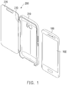
FIG. 1 is a schematic view illustrating an accessory and a portable electronic device according to an embodiment of the application separated from each other. -
FIG. 2 is a schematic view illustrating the accessory and portable electronic device inFIG. 1 assembled together. -
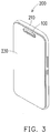
FIG. 3 is a schematic view illustrating a cover portion of the accessory inFIG. 2 covering a display of the portable electronic device. -
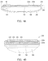
FIG. 4A is a cross-sectional view illustrating the accessory inFIG. 3 taken along line I-I inFIG. 3 . -
FIG. 4B is a partial enlargement view ofportion 4B inFIG. 4A . -
FIG. 5A is a cross-sectional view illustrating a cover portion of the accessory inFIG. 4A being flipped over to the rear side of a coupling portion thereof. -
FIG. 5B is a partial enlargementview illustrating portion 5B inFIG. 5A . -
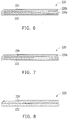
FIG. 6 is a partial enlargement view illustrating a cover portion of an accessory according to another embodiment of the application. -
FIG. 7 is a' partial enlargement view illustrating a cover portion of an accessory according to another embodiment of the application. -
FIG. 8 is a partial enlargement view illustrating a cover portion of an accessory according to another embodiment of the application. -
FIG. 9 is a schematic view illustrating a cover portion of an accessory according to another embodiment of the application. -
FIG. 10 is a schematic view illustrating a cover portion of an accessory according to another embodiment of the application. - Referring to
FIGs. 1-3 , an electronic assembly of the embodiment includes a portableelectronic device 100 and anaccessory 200 for the portableelectronic device 100. Theaccessory 200 may be a cover body which can be flipped over (as shown inFIGs. 2A to 2B ) or slid to open. In the embodiment, the portableelectronic device 100 may be a smart phone, PDA, tablet computer, notebook computer or any portable electronic device having a display. However, in other embodiments that are not shown, the portable electronic device may be a panel device such as a tablet computer or the like. The portableelectronic device 100 includes adisplay 102. Thedisplay 102 may be a liquid crystal display (LCD), an electronic ink display or an organic light emitting diode (OLED) display. Thedisplay 102 may be the whole display or a portion of the display. - Referring to
FIGs. 1-3 , theaccessory 200 includes acoupling portion 210, acover portion 220 and aflexible portion 230. Thecoupling portion 210 is adaptable to be coupled to the portableelectronic device 100. Thecover portion 220 is connected with thecoupling portion 210 and adaptable to cover thedisplay 102 of the portableelectronic device 100. Theflexible portion 230 connects thecover portion 220 to thecoupling portion 210. In particular, the position ofcover portion 220 with respect to thecoupling portion 210 may be changed via bending theflexible portion 230 to decide whether to cover thedisplay 102 of the portableelectronic device 100. Theflexible portion 230 andcover portion 220 may be integrally formed as a single element via an injection molding process or any process. Thecoupling portion 210 may be coupled to the portableelectronic device 100 in four corners thereof to fix thecoupling portion 210 to the portableelectronic device 100. - To couple the
coupling portion 210 to the portableelectronic device 100 so as to fix the position of thecoupling portion 210 with respect to the portableelectronic device 100, thecoupling portion 210 may be a recess and adaptable to structurally cover the external side and bottom of the portableelectronic device 100 so as to fix the position of thecoupling portion 210 with respect to the portableelectronic device 100. Thecover portion 220 andcoupling portion 210 may be formed of a material different from the flexible material. Theflexible portion 230 may be maintained in a bended shape and recovered to the bended shape after a force is applied thereto. - Referring to
FIGs. 3 ,4A and 4B , to determine whether thecover portion 220 covers thedisplay 102, the portableelectronic device 100 includes asensor 104. Theaccessory 200 further includes amagnetic portion 222. The determination of whether thedisplay 102 is covered by thecover portion 220 depends on whether themagnetic portion 222 is sensed by thesensor 104. In the embodiment, thesensor 104 may be a magnetic sensor, a Hall effect sensor, or Hall sensor. Themagnetic portion 222 may be a permanent magnet, an electrical magnet or magnetic test element. Therefore, thecover portion 220 is capable of covering thedisplay 102 of the portableelectronic device 100. Themagnetic portion 222 may cover a portion of thecover portion 220, or cover a corresponding position of thesensor 104 disposed in the portableelectronic device 100. Thesensor 104 is capable of sensing the magnetic pole or magnetic field of themagnetic portion 222. - The position of the
magnetic portion 222 may be in theflexible portion 230 or close to theflexible portion 230. Thesensor 104 of the portableelectronic device 100 may be disposed in theflexible portion 230 or close to theflexible portion 230. When thecover portion 220 is moved from a first position (as shown inFIG. 2 ) to a second position (as shown inFIG. 3 ), themagnetic portion 222 is sensed by thesensor 104 of the portableelectronic device 100. It should be noted that when thecover portion 220 is moved, as compared with an opposite side of thecover portion 220 away from theflexible portion 230, the displacement of thecover portion 220 is less at one side where theflexible portion 230 is disposed. Therefore, the disposition of themagnetic portion 222 may be close to theflexible portion 230 such that the possibility of erroneous detection caused by sudden move of thecover portion 220 may be reduced. In the embodiment, thecover portion 220 may include alogo piece 226, and themagnetic portion 222 may be disposed under thelogo piece 226. - Referring to
FIGs. 3 ,4A and 4B , theaccessory 200 further includes a shieldingportion 224. The shieldingportion 224 may be disposed above themagnetic portion 222 and overlap themagnetic portion 222. When thecover portion 220 covers thedisplay 102 of the portableelectronic device 100, themagnetic portion 222 is disposed between the shieldingportion 224 and portableelectronic device 100. Thecover portion 220 may be flipped over to the rear side of thecoupling portion 210 by twisting or turning theflexible portion 230. - Referring to
FIGs. 5A and 5B , when thecover portion 220 is flipped over to the rear surface of the portableelectronic device 100, the shieldingportion 224 is disposed between themagnetic portion 222 and portableelectronic device 100. Therefore, the shieldingportion 224 is capable of interfering detection of thesensor 104 from the rear side of thecoupling portion 210. By disposing the shieldingportion 224 at a position where thecoupling portion 210 corresponds to thesensor 104 in thecoupling portion 210, the shieldingportion 224 blocks the magnetic field of themagnetic portion 222. - Further referring to
FIGs. 3 ,4A and 4B , themagnetic portion 222 may be disposed within thecover portion 220. Thecover portion 220 further includes ahard layer 220a. Themagnetic portion 222 is disposed on thehard layer 220a and the shieldingportion 224 is disposed above themagnetic portion 222. Specifically, themagnetic portion 222 may be disposed within an opening of thehard layer 220a. A gel may be used to adhere to the shieldingportion 224 andmagnetic portion 222 to thehard layer 220a. Thelogo piece 226 may be disposed on the shieldingportion 224 with anadhesive layer 225 disposed therebetween. Thelogo piece 226 is disposed in thecover portion 220 and overlaps the shieldingportion 224. However, thelogo piece 226 is not necessarily disposed on the shieldingportion 224; thelogo piece 226 may be disposed at other positions of thecover portion 220. When thehard layer 220a is completely transparent or semi-transparent, light can pass through thecover portion 220, and the image shown on thedisplay 102 of the portableelectronic device 100 can pass through thecover portion 220 to be seen by the user. In addition, when thehard layer 220a,magnetic portion 222 and shieldingportion 224 are completely transparent or semi-transparent, light can pass through the cover portion 220 (includingmagnetic portion 222 and shielding portion 224), and the image shown on thedisplay 102 of the portableelectronic device 100 can pass through thecover portion 220 to be seen by the user. In the embodiment, thelogo piece 226 may be completely transparent or semi-transparent. - When the
magnetic portion 222 is completely transparent or semi-transparent, themagnetic portion 222 may be formed of a transparent material mixed with a magnetic material. In other words, themagnetic portion 222 may be constituted by a transparent material and a magnetic material mixed therein. - When the shielding
portion 224 is completely transparent or semi-transparent, the shieldingportion 224 may be an ITO (indium tin oxide) substrate or glass. The substrate may be polymer or a material coated with an ITO pattern or structural layer. In addition, the shieldingportion 224 may be formed of a transparent material mixed with a shielding material. That is, the shieldingportion 224 may be constituted by a transparent material and a shielding material mixed therein. - The
cover portion 220 further includes asoft layer 220b which is completely transparent or semi-transparent. Thehard layer 220a,magnetic portion 222 and shieldingportion 224 may be disposed within thesoft layer 220b. Thesoft layer 220b may be completely transparent or semi-transparent. As compared with thehard layer 220a, thesoft layer 220b is softer and may have different color or different transparency to form thecover portion 220 that exhibits a special visual effect as a whole. Likewise, when themagnetic portion 222 and shieldingportion 224 are completely transparent or semi-transparent, themagnetic portion 222 and shieldingportion 224 may also have different color or different transparency to form thecover portion 220 that exhibits a special visual effect as a whole. - In another embodiment, when the
magnetic portion 222 and shieldingportion 224 are non-transparent, themagnetic portion 222 may be a magnet. The shieldingportion 224 may be any ferromagnetic metal, i.e. any object that contains iron, nickel, or cobalt. The shieldingportion 224 serves as a magnetic shielding that blocks the magnetic field on the rear side of thecoupling portion 210 for thesensor 104. - Referring to
FIG. 6 , as compared with the embodiment inFIG. 3 , thecover portion 220 does not include the logo piece inFIG. 3 ; thus, thesoft layer 220b may cover the shieldingportion 224 to maintain flatness of the appearance ofcover portion 220. - Referring to
FIG. 7 , in the embodiment, themagnetic portion 222 and shieldingportion 224 may be disposed together within thecover portion 220. Specifically, themagnetic portion 222 and shieldingportion 224 may be similarly constituted as thehard layer 220a inFIG. 3 and be covered by thesoft layer 220b. To allow light to pass through thecover portion 220, thehard layer 220a,soft layer 220b,magnetic portion 222 and shieldingportion 224 may be completely transparent or semi-transparent. - Referring to
FIG. 8 , in the embodiment, themagnetic portion 222 may be a structural layer of thecover portion 220, forming into a structure of thecover portion 220 that covers thedisplay 102. In other words, themagnetic portion 222 may be thecover portion 220, and themagnetic portion 222 may a large structural layer that covers theentire display 102. The shieldingportion 224 is disposed above themagnetic portion 222. The position of themagnetic portion 222 may be between the shieldingportion 224 and portableelectronic device 100. Themagnetic portion 222 and shieldingportion 224 together may form thewhole cover portion 220. To allow light to pass through thecover portion 220, themagnetic portion 222 and shieldingportion 224 may be completely transparent or semi-transparent. - Referring to
FIG. 9 , in the embodiment, themagnetic portion 222 may include a plurality of magnetic layers that are arranged in array or matrix on thecover portion 220. The shieldingportion 224 may also include a plurality of shielding layers that are arranged in array or matrix corresponding to themagnetic portion 222 on thecover portion 220. With such configuration, the magnetic layers 222a or shielding layers 224a may be completely transparent or semi-transparent. - Referring to
FIG. 10 , in another embodiment, the shieldingportion 224 may also include a single shielding layer 224a which includes the magnetic layers 222a of themagnetic portion 222 and is disposed on thecover portion 220. With such configuration, the magnetic layers 222a and shielding layers 224a may be completely transparent or semi-transparent. - In summary of the above, in the application, the cover portion of accessory is completely transparent or semi-transparent. When the cover portion covers the display of the portable electronic device, the image shown on the display can pass through the cover portion to be seen by the user. In addition, the accessory can be sensed by the sensor of the portable electronic device via the magnetic field of the magnetic portion disposed in the cover portion. When the cover portion is flipped over to the rear side of the portable electronic device, the magnetic field of the magnetic portion may be blocked via the shielding portion disposed in the cover portion so that the accessory can be sensed by the sensor of the portable electronic device. In addition, the accessory may be in contact with the display of the portable electronic device via the soft layer of the cover portion to avoid scratches caused to the display of the portable electronic device.
- Although the application has been disclosed by the above embodiments, the embodiments are not intended to limit the application. It will be apparent to those skilled in the art that various modifications and variations can be made to the structure of the application without departing from the scope or spirit of the application. Therefore, the protecting range of the application falls in the appended claims.
-
- 1. An accessory, adaptable for a portable electronic device, the portable electronic device comprising a display and a rear surface facing away from the display, the accessory comprising:
- a cover portion being completely transparent or semi-transparent and adaptable to cover the display of the portable electronic device;
- a magnetic portion, disposed within the cover portion; and
- a shielding portion, disposed within the cover portion, wherein when the cover portion covers the display of the portable electronic device, the magnetic portion is disposed between the shielding portion and the portable electronic device, when the cover portion is flipped over to the rear surface of the portable electronic device, the shielding portion is disposed between the magnetic portion and the portable electronic device.
- 2. The accessory according to 1, wherein the magnetic portion is constituted by a transparent material and a magnetic material mixed therein.
- 3. The accessory according to 1, wherein the shielding portion comprises a transparent substrate and a transparent conductive layer disposed on the transparent substrate.
- 4. The accessory according to 1, wherein the shielding portion is constituted by a transparent material and a shielding material mixed therein.
- 5. The accessory according to 1, wherein the magnetic portion comprises a plurality of magnetic layers arranged in array or matrix on the cover portion.
- 6. The accessory according to 5, wherein the shielding portion comprises a plurality of shielding layers respectively arranged on the cover portion corresponding to the magnetic layers.
- 7. The accessory according to 5, wherein the shielding portion comprises a single layer including the magnetic layers and disposed on the cover portion.
- 8. The accessory according to 1, further comprising:
- a logo piece, embedded in the cover portion and overlapping the shielding portion.
- 9. The accessory according to 1, further comprising:
- a coupling portion, connected with the cover portion and adaptable to be coupled to the portable electronic device.
- 10. The accessory according to 1, further comprising:
- a flexible portion, connecting the cover portion to the coupling portion.
- 11. An accessory, adaptable for a portable electronic device, the portable electronic device comprising a display and a rear surface facing away from the display, the accessory comprising:
- a cover portion, comprising a hard layer and a soft layer covering the hard layer, and
- adaptable to cover the display of the portable electronic device;
- a magnetic portion, disposed within the cover portion; and
- a shielding portion, disposed within the cover portion, wherein when the cover portion covers the display of the portable electronic device, the magnetic portion is disposed between the shielding portion and the portable electronic device, when the cover portion is flipped over to the rear surface of the portable electronic device, the shielding portion is disposed between the magnetic portion and the portable electronic device.
- 12. The accessory according to 11, wherein the magnetic portion is disposed within an opening of the hard layer.
- 13. The accessory according to 11, wherein the shielding portion and the magnetic portion are overlapped.
- 14. The accessory according to 11, wherein the magnetic portion is completely transparent or semi-transparent.
- 15. The accessory according to 11, wherein the shielding portion is completely transparent or semi-transparent.
- 16. The accessory according to 11, wherein the magnetic portion comprises a plurality of magnetic layers arranged in array or matrix on the cover portion.
- 17. The accessory according to 16, wherein the shielding portion comprises a plurality of shielding layers respectively arranged on the cover portion corresponding to the magnetic layers.
- 18. The accessory according to 16, wherein the shielding portion comprises a single shielding layer including the magnetic layers and disposed on the cover portion.
- 19. The accessory according to 11, further comprising:
- a logo piece, disposed in the cover portion and overlapping the shielding portion.
- 20. The accessory according to 11, further comprising:
- a coupling portion, connected with the cover portion and adaptable to be coupled to the portable electronic device.
- 21. The accessory according to 11, further comprising:
- a flexible portion, connecting the cover portion to the coupling portion.
Claims (15)
- An accessory, adaptable for a portable electronic device, the portable electronic device comprising a display and a rear surface facing away from the display, the accessory comprising:a cover portion being completely transparent or semi-transparent and adaptable to cover the display of the portable electronic device;a magnetic portion, disposed within the cover portion; anda shielding portion, disposed within the cover portion, wherein when the cover portion covers the display of the portable electronic device, the magnetic portion is disposed between the shielding portion and the portable electronic device, when the cover portion is flipped over to the rear surface of the portable electronic device, the shielding portion is disposed between the magnetic portion and the portable electronic device.
- The accessory according to claim 1, wherein the magnetic portion is constituted by a transparent material and a magnetic material mixed therein.
- The accessory according to claim 1, wherein the shielding portion comprises a transparent substrate and a transparent conductive layer disposed on the transparent substrate.
- The accessory according to claim 1, wherein the shielding portion is constituted by a transparent material and a shielding material mixed therein.
- The accessory according to claim 1, further comprising:a logo piece, embedded in the cover portion and overlapping the shielding portion.
- An accessory, adaptable for a portable electronic device, the portable electronic device comprising a display and a rear surface facing away from the display, the accessory comprising:a cover portion, comprising a hard layer and a soft layer covering the hard layer, and adaptable to cover the display of the portable electronic device;a magnetic portion, disposed within the cover portion; anda shielding portion, disposed within the cover portion, wherein when the cover portion covers the display of the portable electronic device, the magnetic portion is disposed between the shielding portion and the portable electronic device, when the cover portion is flipped over to the rear surface of the portable electronic device, the shielding portion is disposed between the magnetic portion and the portable electronic device.
- The accessory according to claim 6, wherein the magnetic portion is disposed within an opening of the hard layer.
- The accessory according to claim 6, wherein the shielding portion and the magnetic portion are overlapped.
- The accessory according to claim 6, wherein the magnetic portion is completely transparent or semi-transparent.
- The accessory according to claim 6, wherein the shielding portion is completely transparent or semi-transparent.
- The accessory according to claims 1 or 6, wherein the magnetic portion comprises a plurality of magnetic layers arranged in array or matrix on the cover portion.
- The accessory according to claim 11, wherein the shielding portion comprises a plurality of shielding layers respectively arranged on the cover portion corresponding to the magnetic layers, or
wherein the shielding portion comprises a single shielding layer including the magnetic layers and disposed on the cover portion. - The accessory according to claim 6, further comprising:a logo piece, disposed in the cover portion and overlapping the shielding portion.
- The accessory according to claims 1 or 6, further comprising:a coupling portion, connected with the cover portion and adaptable to be coupled to the portable electronic device.
- The accessory according to claims 1 or 6, further comprising:a flexible portion, connecting the cover portion to the coupling portion.
Applications Claiming Priority (2)
| Application Number | Priority Date | Filing Date | Title |
|---|---|---|---|
| US201662313827P | 2016-03-28 | 2016-03-28 | |
| US15/447,139 US20170300085A1 (en) | 2016-03-28 | 2017-03-02 | Accessory for portable electronic device |
Publications (3)
| Publication Number | Publication Date |
|---|---|
| EP3226102A2 true EP3226102A2 (en) | 2017-10-04 |
| EP3226102A3 EP3226102A3 (en) | 2017-12-13 |
| EP3226102B1 EP3226102B1 (en) | 2022-01-05 |
Family
ID=58454915
Family Applications (1)
| Application Number | Title | Priority Date | Filing Date |
|---|---|---|---|
| EP17163350.6A Active EP3226102B1 (en) | 2016-03-28 | 2017-03-28 | Accessory for portable electronic device |
Country Status (4)
| Country | Link |
|---|---|
| US (1) | US20170300085A1 (en) |
| EP (1) | EP3226102B1 (en) |
| CN (1) | CN107239102A (en) |
| TW (1) | TWI651032B (en) |
Families Citing this family (7)
| Publication number | Priority date | Publication date | Assignee | Title |
|---|---|---|---|---|
| USD875725S1 (en) * | 2016-04-01 | 2020-02-18 | Htc Corporation | Cover for electronic communications device |
| WO2018033796A1 (en) * | 2016-08-16 | 2018-02-22 | Rakuten, Inc. | Systems and methods for device case magnets |
| KR102613168B1 (en) * | 2017-01-04 | 2023-12-14 | 삼성전자 주식회사 | Cover accessory and electronic device using the same |
| KR102667275B1 (en) * | 2017-01-04 | 2024-05-21 | 삼성전자주식회사 | Cover and electronic device having thereof |
| US20180324986A1 (en) * | 2017-05-03 | 2018-11-08 | Tsvetana Yvanova | Hi Performance Security Folio for Digital Mobile Devices |
| US10486449B2 (en) | 2017-09-11 | 2019-11-26 | Apple Inc. | Structures for securing operational components in a portable electronic device |
| US11909248B2 (en) * | 2020-06-04 | 2024-02-20 | Apple Inc. | Accessory with a magnetic relay structure for wireless power transfer |
Family Cites Families (12)
| Publication number | Priority date | Publication date | Assignee | Title |
|---|---|---|---|---|
| US7643274B2 (en) * | 2006-04-21 | 2010-01-05 | Tech Shell Inc. | Protective cover for laptop computer |
| US20090194445A1 (en) * | 2008-02-01 | 2009-08-06 | Ryan Mongan | Electronic device carrying sleeve |
| KR20080055767A (en) * | 2008-05-21 | 2008-06-19 | 임병윤 | Electromagnetic shielding of TVs, computers, mobile phones, cordless phones, glasses, security screens and screen protectors |
| US8242868B2 (en) * | 2010-09-17 | 2012-08-14 | Apple Inc. | Methods and apparatus for configuring a magnetic attachment system |
| US20150357065A1 (en) * | 2011-12-14 | 2015-12-10 | Icaro Innovations Corporation | Body shield for thermal and electromagnetic radiation |
| CN103729026B (en) * | 2012-10-16 | 2017-09-01 | 华硕电脑股份有限公司 | protection cap |
| KR102060756B1 (en) * | 2013-03-14 | 2019-12-30 | 삼성전자주식회사 | Electronic device with protective case and operating method thereof |
| CN203524031U (en) * | 2013-09-22 | 2014-04-09 | 东莞宇龙通信科技有限公司 | A protective cover for a mobile terminal |
| FR3013472B1 (en) * | 2013-11-19 | 2016-07-08 | Fogale Nanotech | COVERING ACCESSORY DEVICE FOR AN ELECTRONIC AND / OR COMPUTER PORTABLE APPARATUS, AND APPARATUS EQUIPPED WITH SUCH AN ACCESSORY DEVICE |
| CN103701961B (en) * | 2013-12-26 | 2016-07-13 | 惠州Tcl移动通信有限公司 | A kind of structure preventing mobile terminal protection set to be turned over and turning screen off and method |
| US9300774B2 (en) * | 2014-01-03 | 2016-03-29 | Choon-Teak Oh | Mobile terminal and its case with hall IC driving shield magnet |
| KR102301715B1 (en) * | 2015-04-30 | 2021-09-14 | 삼성전자주식회사 | Accessory device and electronic device including the same |
-
2017
- 2017-03-02 US US15/447,139 patent/US20170300085A1/en not_active Abandoned
- 2017-03-15 TW TW106108471A patent/TWI651032B/en active
- 2017-03-23 CN CN201710179070.1A patent/CN107239102A/en active Pending
- 2017-03-28 EP EP17163350.6A patent/EP3226102B1/en active Active
Non-Patent Citations (1)
| Title |
|---|
| None |
Also Published As
| Publication number | Publication date |
|---|---|
| TW201735760A (en) | 2017-10-01 |
| EP3226102B1 (en) | 2022-01-05 |
| TWI651032B (en) | 2019-02-11 |
| US20170300085A1 (en) | 2017-10-19 |
| CN107239102A (en) | 2017-10-10 |
| EP3226102A3 (en) | 2017-12-13 |
Similar Documents
| Publication | Publication Date | Title |
|---|---|---|
| US20170300085A1 (en) | Accessory for portable electronic device | |
| KR102351372B1 (en) | Electronic device with display | |
| KR102458284B1 (en) | Display apparatus and portable terminal | |
| US10775849B2 (en) | Flexible device and method for manufacturing same | |
| CN114141136B (en) | Display device | |
| US9232674B2 (en) | Cover structure and electronic device using the same | |
| TWI492136B (en) | Protective device of portable mobile device | |
| CN104933970B (en) | Display components and terminals | |
| KR102604087B1 (en) | Window and display apparatus having the same | |
| US20150018045A1 (en) | Cover device and portable terminal having the same | |
| CN115443497B (en) | Electronic device comprising a transparent cover comprising glass and a foldable display coupled thereto | |
| KR20200099632A (en) | Display device | |
| KR20200132150A (en) | Foldable electronic device | |
| TWI681282B (en) | Bent display panel with electrical lines for a sensor | |
| US20160282977A1 (en) | Capacitive sensing assembly including a thin film plastic | |
| JP2011107989A (en) | Portable device | |
| US10098245B2 (en) | Display assembly, electronic device and method for assembling the same | |
| KR102688018B1 (en) | Nput sensing unit, display device including same, and method for manufacturing same | |
| KR101373641B1 (en) | Input device, display device, and portable terminal | |
| CN103092413A (en) | Three-dimensional transparent base material, touch plate, liquid crystal display screen and electronic equipment | |
| US20130314327A1 (en) | Frameless touch panel | |
| US20130043081A1 (en) | Multi-function touch panel | |
| US20250151220A1 (en) | Electronic device including flexible display | |
| US9513728B2 (en) | Touch sensor applied on large size display | |
| US20130021731A1 (en) | Removable cover panel for display housing |
Legal Events
| Date | Code | Title | Description |
|---|---|---|---|
| PUAI | Public reference made under article 153(3) epc to a published international application that has entered the european phase |
Free format text: ORIGINAL CODE: 0009012 |
|
| STAA | Information on the status of an ep patent application or granted ep patent |
Free format text: STATUS: REQUEST FOR EXAMINATION WAS MADE |
|
| 17P | Request for examination filed |
Effective date: 20170328 |
|
| AK | Designated contracting states |
Kind code of ref document: A2 Designated state(s): AL AT BE BG CH CY CZ DE DK EE ES FI FR GB GR HR HU IE IS IT LI LT LU LV MC MK MT NL NO PL PT RO RS SE SI SK SM TR |
|
| AX | Request for extension of the european patent |
Extension state: BA ME |
|
| PUAL | Search report despatched |
Free format text: ORIGINAL CODE: 0009013 |
|
| STAA | Information on the status of an ep patent application or granted ep patent |
Free format text: STATUS: EXAMINATION IS IN PROGRESS |
|
| AK | Designated contracting states |
Kind code of ref document: A3 Designated state(s): AL AT BE BG CH CY CZ DE DK EE ES FI FR GB GR HR HU IE IS IT LI LT LU LV MC MK MT NL NO PL PT RO RS SE SI SK SM TR |
|
| AX | Request for extension of the european patent |
Extension state: BA ME |
|
| RIC1 | Information provided on ipc code assigned before grant |
Ipc: G06F 1/16 20060101AFI20171107BHEP Ipc: A45C 11/00 20060101ALN20171107BHEP |
|
| 17Q | First examination report despatched |
Effective date: 20171124 |
|
| RBV | Designated contracting states (corrected) |
Designated state(s): AL AT BE BG CH CY CZ DE DK EE ES FI FR GB GR HR HU IE IS IT LI LT LU LV MC MK MT NL NO PL PT RO RS SE SI SK SM TR |
|
| GRAP | Despatch of communication of intention to grant a patent |
Free format text: ORIGINAL CODE: EPIDOSNIGR1 |
|
| STAA | Information on the status of an ep patent application or granted ep patent |
Free format text: STATUS: GRANT OF PATENT IS INTENDED |
|
| RIC1 | Information provided on ipc code assigned before grant |
Ipc: G06F 1/16 20060101AFI20210713BHEP Ipc: H04B 1/3888 20150101ALI20210713BHEP Ipc: H04M 1/04 20060101ALI20210713BHEP Ipc: A45C 11/00 20060101ALN20210713BHEP |
|
| INTG | Intention to grant announced |
Effective date: 20210805 |
|
| RIC1 | Information provided on ipc code assigned before grant |
Ipc: G06F 1/16 20060101AFI20210723BHEP Ipc: H04B 1/3888 20150101ALI20210723BHEP Ipc: H04M 1/04 20060101ALI20210723BHEP Ipc: A45C 11/00 20060101ALN20210723BHEP |
|
| RIN1 | Information on inventor provided before grant (corrected) |
Inventor name: HINTERMANN, MATHIAS ANDREAS |
|
| GRAS | Grant fee paid |
Free format text: ORIGINAL CODE: EPIDOSNIGR3 |
|
| GRAA | (expected) grant |
Free format text: ORIGINAL CODE: 0009210 |
|
| STAA | Information on the status of an ep patent application or granted ep patent |
Free format text: STATUS: THE PATENT HAS BEEN GRANTED |
|
| AK | Designated contracting states |
Kind code of ref document: B1 Designated state(s): AL AT BE BG CH CY CZ DE DK EE ES FI FR GB GR HR HU IE IS IT LI LT LU LV MC MK MT NL NO PL PT RO RS SE SI SK SM TR |
|
| REG | Reference to a national code |
Ref country code: GB Ref legal event code: FG4D |
|
| REG | Reference to a national code |
Ref country code: CH Ref legal event code: EP |
|
| REG | Reference to a national code |
Ref country code: AT Ref legal event code: REF Ref document number: 1461156 Country of ref document: AT Kind code of ref document: T Effective date: 20220115 |
|
| REG | Reference to a national code |
Ref country code: DE Ref legal event code: R096 Ref document number: 602017051769 Country of ref document: DE |
|
| REG | Reference to a national code |
Ref country code: IE Ref legal event code: FG4D |
|
| REG | Reference to a national code |
Ref country code: NL Ref legal event code: FP |
|
| REG | Reference to a national code |
Ref country code: LT Ref legal event code: MG9D |
|
| REG | Reference to a national code |
Ref country code: AT Ref legal event code: MK05 Ref document number: 1461156 Country of ref document: AT Kind code of ref document: T Effective date: 20220105 |
|
| PG25 | Lapsed in a contracting state [announced via postgrant information from national office to epo] |
Ref country code: SE Free format text: LAPSE BECAUSE OF FAILURE TO SUBMIT A TRANSLATION OF THE DESCRIPTION OR TO PAY THE FEE WITHIN THE PRESCRIBED TIME-LIMIT Effective date: 20220105 Ref country code: RS Free format text: LAPSE BECAUSE OF FAILURE TO SUBMIT A TRANSLATION OF THE DESCRIPTION OR TO PAY THE FEE WITHIN THE PRESCRIBED TIME-LIMIT Effective date: 20220105 Ref country code: PT Free format text: LAPSE BECAUSE OF FAILURE TO SUBMIT A TRANSLATION OF THE DESCRIPTION OR TO PAY THE FEE WITHIN THE PRESCRIBED TIME-LIMIT Effective date: 20220505 Ref country code: NO Free format text: LAPSE BECAUSE OF FAILURE TO SUBMIT A TRANSLATION OF THE DESCRIPTION OR TO PAY THE FEE WITHIN THE PRESCRIBED TIME-LIMIT Effective date: 20220405 Ref country code: LT Free format text: LAPSE BECAUSE OF FAILURE TO SUBMIT A TRANSLATION OF THE DESCRIPTION OR TO PAY THE FEE WITHIN THE PRESCRIBED TIME-LIMIT Effective date: 20220105 Ref country code: HR Free format text: LAPSE BECAUSE OF FAILURE TO SUBMIT A TRANSLATION OF THE DESCRIPTION OR TO PAY THE FEE WITHIN THE PRESCRIBED TIME-LIMIT Effective date: 20220105 Ref country code: ES Free format text: LAPSE BECAUSE OF FAILURE TO SUBMIT A TRANSLATION OF THE DESCRIPTION OR TO PAY THE FEE WITHIN THE PRESCRIBED TIME-LIMIT Effective date: 20220105 Ref country code: BG Free format text: LAPSE BECAUSE OF FAILURE TO SUBMIT A TRANSLATION OF THE DESCRIPTION OR TO PAY THE FEE WITHIN THE PRESCRIBED TIME-LIMIT Effective date: 20220405 |
|
| PG25 | Lapsed in a contracting state [announced via postgrant information from national office to epo] |
Ref country code: PL Free format text: LAPSE BECAUSE OF FAILURE TO SUBMIT A TRANSLATION OF THE DESCRIPTION OR TO PAY THE FEE WITHIN THE PRESCRIBED TIME-LIMIT Effective date: 20220105 Ref country code: LV Free format text: LAPSE BECAUSE OF FAILURE TO SUBMIT A TRANSLATION OF THE DESCRIPTION OR TO PAY THE FEE WITHIN THE PRESCRIBED TIME-LIMIT Effective date: 20220105 Ref country code: GR Free format text: LAPSE BECAUSE OF FAILURE TO SUBMIT A TRANSLATION OF THE DESCRIPTION OR TO PAY THE FEE WITHIN THE PRESCRIBED TIME-LIMIT Effective date: 20220406 Ref country code: FI Free format text: LAPSE BECAUSE OF FAILURE TO SUBMIT A TRANSLATION OF THE DESCRIPTION OR TO PAY THE FEE WITHIN THE PRESCRIBED TIME-LIMIT Effective date: 20220105 Ref country code: AT Free format text: LAPSE BECAUSE OF FAILURE TO SUBMIT A TRANSLATION OF THE DESCRIPTION OR TO PAY THE FEE WITHIN THE PRESCRIBED TIME-LIMIT Effective date: 20220105 |
|
| PG25 | Lapsed in a contracting state [announced via postgrant information from national office to epo] |
Ref country code: IS Free format text: LAPSE BECAUSE OF FAILURE TO SUBMIT A TRANSLATION OF THE DESCRIPTION OR TO PAY THE FEE WITHIN THE PRESCRIBED TIME-LIMIT Effective date: 20220505 |
|
| REG | Reference to a national code |
Ref country code: DE Ref legal event code: R097 Ref document number: 602017051769 Country of ref document: DE |
|
| PG25 | Lapsed in a contracting state [announced via postgrant information from national office to epo] |
Ref country code: SM Free format text: LAPSE BECAUSE OF FAILURE TO SUBMIT A TRANSLATION OF THE DESCRIPTION OR TO PAY THE FEE WITHIN THE PRESCRIBED TIME-LIMIT Effective date: 20220105 Ref country code: SK Free format text: LAPSE BECAUSE OF FAILURE TO SUBMIT A TRANSLATION OF THE DESCRIPTION OR TO PAY THE FEE WITHIN THE PRESCRIBED TIME-LIMIT Effective date: 20220105 Ref country code: RO Free format text: LAPSE BECAUSE OF FAILURE TO SUBMIT A TRANSLATION OF THE DESCRIPTION OR TO PAY THE FEE WITHIN THE PRESCRIBED TIME-LIMIT Effective date: 20220105 Ref country code: MC Free format text: LAPSE BECAUSE OF FAILURE TO SUBMIT A TRANSLATION OF THE DESCRIPTION OR TO PAY THE FEE WITHIN THE PRESCRIBED TIME-LIMIT Effective date: 20220105 Ref country code: EE Free format text: LAPSE BECAUSE OF FAILURE TO SUBMIT A TRANSLATION OF THE DESCRIPTION OR TO PAY THE FEE WITHIN THE PRESCRIBED TIME-LIMIT Effective date: 20220105 Ref country code: DK Free format text: LAPSE BECAUSE OF FAILURE TO SUBMIT A TRANSLATION OF THE DESCRIPTION OR TO PAY THE FEE WITHIN THE PRESCRIBED TIME-LIMIT Effective date: 20220105 Ref country code: CZ Free format text: LAPSE BECAUSE OF FAILURE TO SUBMIT A TRANSLATION OF THE DESCRIPTION OR TO PAY THE FEE WITHIN THE PRESCRIBED TIME-LIMIT Effective date: 20220105 |
|
| REG | Reference to a national code |
Ref country code: CH Ref legal event code: PL |
|
| PLBE | No opposition filed within time limit |
Free format text: ORIGINAL CODE: 0009261 |
|
| STAA | Information on the status of an ep patent application or granted ep patent |
Free format text: STATUS: NO OPPOSITION FILED WITHIN TIME LIMIT |
|
| PG25 | Lapsed in a contracting state [announced via postgrant information from national office to epo] |
Ref country code: AL Free format text: LAPSE BECAUSE OF FAILURE TO SUBMIT A TRANSLATION OF THE DESCRIPTION OR TO PAY THE FEE WITHIN THE PRESCRIBED TIME-LIMIT Effective date: 20220105 |
|
| REG | Reference to a national code |
Ref country code: BE Ref legal event code: MM Effective date: 20220331 |
|
| 26N | No opposition filed |
Effective date: 20221006 |
|
| PG25 | Lapsed in a contracting state [announced via postgrant information from national office to epo] |
Ref country code: LU Free format text: LAPSE BECAUSE OF NON-PAYMENT OF DUE FEES Effective date: 20220328 Ref country code: LI Free format text: LAPSE BECAUSE OF NON-PAYMENT OF DUE FEES Effective date: 20220331 Ref country code: IE Free format text: LAPSE BECAUSE OF NON-PAYMENT OF DUE FEES Effective date: 20220328 Ref country code: CH Free format text: LAPSE BECAUSE OF NON-PAYMENT OF DUE FEES Effective date: 20220331 |
|
| PG25 | Lapsed in a contracting state [announced via postgrant information from national office to epo] |
Ref country code: SI Free format text: LAPSE BECAUSE OF FAILURE TO SUBMIT A TRANSLATION OF THE DESCRIPTION OR TO PAY THE FEE WITHIN THE PRESCRIBED TIME-LIMIT Effective date: 20220105 Ref country code: BE Free format text: LAPSE BECAUSE OF NON-PAYMENT OF DUE FEES Effective date: 20220331 |
|
| P01 | Opt-out of the competence of the unified patent court (upc) registered |
Effective date: 20230602 |
|
| PG25 | Lapsed in a contracting state [announced via postgrant information from national office to epo] |
Ref country code: IT Free format text: LAPSE BECAUSE OF FAILURE TO SUBMIT A TRANSLATION OF THE DESCRIPTION OR TO PAY THE FEE WITHIN THE PRESCRIBED TIME-LIMIT Effective date: 20220105 |
|
| PG25 | Lapsed in a contracting state [announced via postgrant information from national office to epo] |
Ref country code: HU Free format text: LAPSE BECAUSE OF FAILURE TO SUBMIT A TRANSLATION OF THE DESCRIPTION OR TO PAY THE FEE WITHIN THE PRESCRIBED TIME-LIMIT; INVALID AB INITIO Effective date: 20170328 |
|
| PG25 | Lapsed in a contracting state [announced via postgrant information from national office to epo] |
Ref country code: MK Free format text: LAPSE BECAUSE OF FAILURE TO SUBMIT A TRANSLATION OF THE DESCRIPTION OR TO PAY THE FEE WITHIN THE PRESCRIBED TIME-LIMIT Effective date: 20220105 Ref country code: CY Free format text: LAPSE BECAUSE OF FAILURE TO SUBMIT A TRANSLATION OF THE DESCRIPTION OR TO PAY THE FEE WITHIN THE PRESCRIBED TIME-LIMIT Effective date: 20220105 |
|
| PG25 | Lapsed in a contracting state [announced via postgrant information from national office to epo] |
Ref country code: TR Free format text: LAPSE BECAUSE OF FAILURE TO SUBMIT A TRANSLATION OF THE DESCRIPTION OR TO PAY THE FEE WITHIN THE PRESCRIBED TIME-LIMIT Effective date: 20220105 |
|
| PG25 | Lapsed in a contracting state [announced via postgrant information from national office to epo] |
Ref country code: MT Free format text: LAPSE BECAUSE OF FAILURE TO SUBMIT A TRANSLATION OF THE DESCRIPTION OR TO PAY THE FEE WITHIN THE PRESCRIBED TIME-LIMIT Effective date: 20220105 |
|
| PGFP | Annual fee paid to national office [announced via postgrant information from national office to epo] |
Ref country code: NL Payment date: 20250107 Year of fee payment: 9 |
|
| PGFP | Annual fee paid to national office [announced via postgrant information from national office to epo] |
Ref country code: DE Payment date: 20241231 Year of fee payment: 9 |
|
| PGFP | Annual fee paid to national office [announced via postgrant information from national office to epo] |
Ref country code: FR Payment date: 20250210 Year of fee payment: 9 |
|
| PGFP | Annual fee paid to national office [announced via postgrant information from national office to epo] |
Ref country code: GB Payment date: 20250102 Year of fee payment: 9 |