EP3226031A1 - Laser scanner - Google Patents
Laser scanner Download PDFInfo
- Publication number
- EP3226031A1 EP3226031A1 EP17163391.0A EP17163391A EP3226031A1 EP 3226031 A1 EP3226031 A1 EP 3226031A1 EP 17163391 A EP17163391 A EP 17163391A EP 3226031 A1 EP3226031 A1 EP 3226031A1
- Authority
- EP
- European Patent Office
- Prior art keywords
- laser scanner
- scanner device
- view
- horizontal
- laser
- Prior art date
- Legal status (The legal status is an assumption and is not a legal conclusion. Google has not performed a legal analysis and makes no representation as to the accuracy of the status listed.)
- Ceased
Links
Images



Classifications
-
- G—PHYSICS
- G01—MEASURING; TESTING
- G01S—RADIO DIRECTION-FINDING; RADIO NAVIGATION; DETERMINING DISTANCE OR VELOCITY BY USE OF RADIO WAVES; LOCATING OR PRESENCE-DETECTING BY USE OF THE REFLECTION OR RERADIATION OF RADIO WAVES; ANALOGOUS ARRANGEMENTS USING OTHER WAVES
- G01S7/00—Details of systems according to groups G01S13/00, G01S15/00, G01S17/00
- G01S7/48—Details of systems according to groups G01S13/00, G01S15/00, G01S17/00 of systems according to group G01S17/00
- G01S7/481—Constructional features, e.g. arrangements of optical elements
- G01S7/4817—Constructional features, e.g. arrangements of optical elements relating to scanning
-
- G—PHYSICS
- G01—MEASURING; TESTING
- G01S—RADIO DIRECTION-FINDING; RADIO NAVIGATION; DETERMINING DISTANCE OR VELOCITY BY USE OF RADIO WAVES; LOCATING OR PRESENCE-DETECTING BY USE OF THE REFLECTION OR RERADIATION OF RADIO WAVES; ANALOGOUS ARRANGEMENTS USING OTHER WAVES
- G01S17/00—Systems using the reflection or reradiation of electromagnetic waves other than radio waves, e.g. lidar systems
- G01S17/02—Systems using the reflection of electromagnetic waves other than radio waves
- G01S17/06—Systems determining position data of a target
- G01S17/08—Systems determining position data of a target for measuring distance only
-
- G—PHYSICS
- G01—MEASURING; TESTING
- G01S—RADIO DIRECTION-FINDING; RADIO NAVIGATION; DETERMINING DISTANCE OR VELOCITY BY USE OF RADIO WAVES; LOCATING OR PRESENCE-DETECTING BY USE OF THE REFLECTION OR RERADIATION OF RADIO WAVES; ANALOGOUS ARRANGEMENTS USING OTHER WAVES
- G01S17/00—Systems using the reflection or reradiation of electromagnetic waves other than radio waves, e.g. lidar systems
- G01S17/02—Systems using the reflection of electromagnetic waves other than radio waves
- G01S17/06—Systems determining position data of a target
- G01S17/42—Simultaneous measurement of distance and other co-ordinates
-
- G—PHYSICS
- G01—MEASURING; TESTING
- G01S—RADIO DIRECTION-FINDING; RADIO NAVIGATION; DETERMINING DISTANCE OR VELOCITY BY USE OF RADIO WAVES; LOCATING OR PRESENCE-DETECTING BY USE OF THE REFLECTION OR RERADIATION OF RADIO WAVES; ANALOGOUS ARRANGEMENTS USING OTHER WAVES
- G01S17/00—Systems using the reflection or reradiation of electromagnetic waves other than radio waves, e.g. lidar systems
- G01S17/88—Lidar systems specially adapted for specific applications
- G01S17/89—Lidar systems specially adapted for specific applications for mapping or imaging
-
- G—PHYSICS
- G02—OPTICS
- G02B—OPTICAL ELEMENTS, SYSTEMS OR APPARATUS
- G02B26/00—Optical devices or arrangements for the control of light using movable or deformable optical elements
- G02B26/08—Optical devices or arrangements for the control of light using movable or deformable optical elements for controlling the direction of light
- G02B26/10—Scanning systems
- G02B26/105—Scanning systems with one or more pivoting mirrors or galvano-mirrors
-
- G—PHYSICS
- G05—CONTROLLING; REGULATING
- G05D—SYSTEMS FOR CONTROLLING OR REGULATING NON-ELECTRIC VARIABLES
- G05D1/00—Control of position, course, altitude or attitude of land, water, air or space vehicles, e.g. using automatic pilots
- G05D1/02—Control of position or course in two dimensions
- G05D1/021—Control of position or course in two dimensions specially adapted to land vehicles
- G05D1/0231—Control of position or course in two dimensions specially adapted to land vehicles using optical position detecting means
- G05D1/0234—Control of position or course in two dimensions specially adapted to land vehicles using optical position detecting means using optical markers or beacons
- G05D1/0236—Control of position or course in two dimensions specially adapted to land vehicles using optical position detecting means using optical markers or beacons in combination with a laser
Definitions
- the present invention pertains to a laser scanner device having a LIDAR (light detection and ranging) module working based on TOF-WFD (time-of-flight waveform digitizing).
- LIDAR light detection and ranging
- TOF-WFD time-of-flight waveform digitizing
- LIDAR modules working based on TOF-WFD are well known in the art, and implemented e. g. within the ScanStations P20, P30 and P40 of Leica Geosystems.
- Such LIDAR modules based on TOF-WFD technology can be equipped with lasers of diffraction limited beam divergence, and the receiving unit with at least one avalanche photodiode.
- the roads be thoroughly mapped in advance. This can be done by special cars that have some kind of scanner device to scan and map the respective area.
- the LIDAR module For use on such a car for mapping the road, the LIDAR module has special requirements with respect to the scanning field-of-view (FOV) combined with a high frame rate.
- the horizontal field-of-view (HFOV) should be about 80°, whereas the vertical field-of-view (VFOV) can be considerably smaller (about ⁇ 25°).
- An instantaneous vertical field-of-view (iVFOV) needs only to be about ⁇ 5°.
- the frame rate for scanning this FOV should be at least 25Hz. To adjust for this special request, new components and technology platforms are necessary.
- At least one of these objects is achieved by the laser scanner device of claim 1 and/or the dependent claims of the present invention.
- the device has a horizontal field of view of at least 60°, an instantaneous vertical field of view of at least ⁇ 2°, a scan resolution of at least one point per 0.8° in horizontal and vertical direction, and a frame rate of at least 10Hz for scanning at least the entire horizontal and instantaneous vertical field of view with said scan resolution.
- the device comprises a rotating mirror for steering a scanning beam horizontally in a uniform manner.
- the device comprises a galvano for steering a scanning beam horizontally in a non-uniform manner.
- the device for steering the scanning beam vertically in the instantaneous vertical field of view, the device comprises a polygon, a mirror and/or MEMS.
- the device comprises a tilt mechanism for tilting the device to achieve an overall vertical field of view of at least ⁇ 25°.
- the device comprises a housing which encompasses the at least one laser module and all beam steering elements.
- the housing is suspended tiltably, particularly by means of a tilt mechanism that is adapted to tilt the housing to achieve an overall vertical field of view of at least ⁇ 25°.
- the device comprises a fixed receiver having at least 32 detectors, in particular at least 64 detectors.
- the device comprises a uniform scan resolution of at least 0.15°.
- the device comprises a non-uniform scan resolution, particularly of between 0.15° and 0.3°, particularly wherein a point density of the non-uniform scan increases towards the edges of the field of view.
- the device comprises a rectangular receiver optics aperture, particularly of about 25x30mm.
- the device comprises at least two laser sources, particularly comprising a fibre splitter.
- the device has a horizontal field of view of at least 70°, in particular at least 80°.
- the device has an instantaneous vertical field of view of at least ⁇ 3°, in particular at least ⁇ 5°.
- the device has a scan resolution of at least one point per 0.5° in horizontal and vertical direction, in particular one point per 0.3°.
- the device has a frame rate of at least 20Hz, particularly at least 25Hz, for scanning at least the entire horizontal and instantaneous vertical field of view with said scan resolution.
- Figure 1 shows a custom laser scanner (e. g. a Leica Geosystems ScanStation P40) mounted horizontally at a suitable height at the front of a car.
- This setup allows a qualitative analysis of range performance, accuracy, dynamic range (road-sign scans) and tarmac scans (low reflectivity at high ranges and low incident angles).
- a full VFOV and HFOV scan for post-processing can be achieved with an angular resolution of 0.15° (vertical and horizontal).
- a customized mechanical mount for horizontal scanner applications could provide an evaluation platform to assess the LIDAR performance within a dynamic application.
- a fixed configuration for single trace scans and a rotatable configuration for full FOV scans with single traces are possible.
- Figures 2a , 2b and 2c show a second exemplary embodiment of the laser scanner device according to the invention.
- this embodiment comprises a common and compact housing to house all beam steering elements.
- the shown embodiment is based on a fast rotating polygon wheel projecting the instantaneous Field of View (iVFOV), and either a fixed rotating mirror or a dynamically rotating galvano projecting the horizontal field of view (HFOV).
- Figures 3a and 3b show achievable advantageous dimensions of the device in mm.
- Figure 4 shows a non-uniform point distribution along the horizontal direction (HFOV) due to the galvano scan mechanism.
- the iVFOV and VFOV scan patterns remain uniform. From an application point of view the non-uniform point density towards the edge of the window provides following advantages:
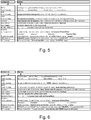
- Figures 5 and 6 each show a morphological analysis of technologies that can be used to constitute a device according to the second embodiment. Advantageous examples are indicated by bold type.
- Figure 7 shows parameter values for an exemplary embodiment of the scanner according to the invention.
Landscapes
- Physics & Mathematics (AREA)
- Engineering & Computer Science (AREA)
- General Physics & Mathematics (AREA)
- Computer Networks & Wireless Communication (AREA)
- Radar, Positioning & Navigation (AREA)
- Remote Sensing (AREA)
- Electromagnetism (AREA)
- Optics & Photonics (AREA)
- Optical Radar Systems And Details Thereof (AREA)
- Mechanical Optical Scanning Systems (AREA)
Abstract
Description
- The present invention pertains to a laser scanner device having a LIDAR (light detection and ranging) module working based on TOF-WFD (time-of-flight waveform digitizing).
- LIDAR modules working based on TOF-WFD are well known in the art, and implemented e. g. within the ScanStations P20, P30 and P40 of Leica Geosystems.
- Such LIDAR modules based on TOF-WFD technology can be equipped with lasers of diffraction limited beam divergence, and the receiving unit with at least one avalanche photodiode.
- For running autonomous cars, it is preferred to have the roads be thoroughly mapped in advance. This can be done by special cars that have some kind of scanner device to scan and map the respective area.
- For use on such a car for mapping the road, the LIDAR module has special requirements with respect to the scanning field-of-view (FOV) combined with a high frame rate. The horizontal field-of-view (HFOV) should be about 80°, whereas the vertical field-of-view (VFOV) can be considerably smaller (about ± 25°). An instantaneous vertical field-of-view (iVFOV) needs only to be about ± 5°. The frame rate for scanning this FOV should be at least 25Hz. To adjust for this special request, new components and technology platforms are necessary.
- It is therefore an object of the present invention to provide an improved LIDAR scanner device.
- It is a particular object to provide such a device which fulfils the requirements stated above.
- It is another object to provide such a LIDAR scanner device that is useable in an autonomous car or similar vehicle.
- At least one of these objects is achieved by the laser scanner device of
claim 1 and/or the dependent claims of the present invention. - According to the invention, a laser scanner device adapted to be mounted to a vehicle comprises a LIDAR module, in particular working based on emitted laser pulses and time-of-flight-measurement-principle, more particular using the technology of waveform digitizing, the LIDAR module comprising at least one laser source. The device has a horizontal field of view of at least 60°, an instantaneous vertical field of view of at least ± 2°, a scan resolution of at least one point per 0.8° in horizontal and vertical direction, and a frame rate of at least 10Hz for scanning at least the entire horizontal and instantaneous vertical field of view with said scan resolution.
- In one embodiment, the device comprises a rotating mirror for steering a scanning beam horizontally in a uniform manner.
- In another embodiment, the device comprises a galvano for steering a scanning beam horizontally in a non-uniform manner.
- According to yet another embodiment, for steering the scanning beam vertically in the instantaneous vertical field of view, the device comprises a polygon, a mirror and/or MEMS.
- In one embodiment, the device comprises a tilt mechanism for tilting the device to achieve an overall vertical field of view of at least ± 25°.
- In one embodiment, the device comprises a housing which encompasses the at least one laser module and all beam steering elements.
- In one embodiment, the housing is suspended tiltably, particularly by means of a tilt mechanism that is adapted to tilt the housing to achieve an overall vertical field of view of at least ± 25°.
- In one embodiment, the device comprises a fixed receiver having at least 32 detectors, in particular at least 64 detectors.
- In one embodiment, the device comprises a uniform scan resolution of at least 0.15°.
- In one embodiment, the device comprises a non-uniform scan resolution, particularly of between 0.15° and 0.3°, particularly wherein a point density of the non-uniform scan increases towards the edges of the field of view.
- In one embodiment, the device comprises a rectangular receiver optics aperture, particularly of about 25x30mm.
- In one embodiment, the device comprises at least two laser sources, particularly comprising a fibre splitter.
- In one embodiment, the device has a horizontal field of view of at least 70°, in particular at least 80°.
- In one embodiment, the device has an instantaneous vertical field of view of at least ± 3°, in particular at least ± 5°.
- In one embodiment, the device has a scan resolution of at least one point per 0.5° in horizontal and vertical direction, in particular one point per 0.3°.
- In one embodiment, the device has a frame rate of at least 20Hz, particularly at least 25Hz, for scanning at least the entire horizontal and instantaneous vertical field of view with said scan resolution.
- The invention in the following will be described in detail by referring to exemplary embodiments that are accompanied by figures, in which:
- Fig. 1
- shows a custom mechanical mount for horizontal laser scanner operation as a first exemplary embodiment of the scanner device according to the invention;
- Figs. 2a-c
- show a second exemplary embodiment of the scanner device according to the invention with its inside components;
- Figs. 3a-b
- show the mechanical dimensions of the second embodiment;
- Fig. 4
- shows a non-uniform point distribution in horizontal direction for the second embodiment having an oscillating galvano mirror;
- Fig. 5
- shows a first exemplary solution path for the second embodiment;
- Fig. 6
- shows a second exemplary solution path for the second embodiment; and
- Fig. 7
- shows parameter values for an exemplary embodiment of the scanner according to the invention.
-
Figure 1 shows a custom laser scanner (e. g. a Leica Geosystems ScanStation P40) mounted horizontally at a suitable height at the front of a car. This setup allows a qualitative analysis of range performance, accuracy, dynamic range (road-sign scans) and tarmac scans (low reflectivity at high ranges and low incident angles). - A full VFOV and HFOV scan for post-processing can be achieved with an angular resolution of 0.15° (vertical and horizontal). A customized mechanical mount for horizontal scanner applications could provide an evaluation platform to assess the LIDAR performance within a dynamic application. A fixed configuration for single trace scans and a rotatable configuration for full FOV scans with single traces are possible.
-
Figures 2a ,2b and 2c show a second exemplary embodiment of the laser scanner device according to the invention. In contrast to the solution shown inFigure 1 , this embodiment comprises a common and compact housing to house all beam steering elements. Conceptually, the shown embodiment is based on a fast rotating polygon wheel projecting the instantaneous Field of View (iVFOV), and either a fixed rotating mirror or a dynamically rotating galvano projecting the horizontal field of view (HFOV).Figures 3a and 3b show achievable advantageous dimensions of the device in mm. -
Figure 4 shows a non-uniform point distribution along the horizontal direction (HFOV) due to the galvano scan mechanism. The iVFOV and VFOV scan patterns remain uniform. From an application point of view the non-uniform point density towards the edge of the window provides following advantages: - 1. Increased projected point pattern for objects seen under a low angle of incidence, e. g. buildings along the road; and
- 2. Increased information density, e. g. detection of objects accidentally crossing a street.
-
Figures 5 and 6 each show a morphological analysis of technologies that can be used to constitute a device according to the second embodiment. Advantageous examples are indicated by bold type. -
Figure 7 shows parameter values for an exemplary embodiment of the scanner according to the invention. - Although the invention is illustrated above, partly with reference to some preferred embodiments, it must be understood that numerous modifications and combinations of different features of the embodiments can be made. All of these modifications lie within the scope of the appended claims.
Claims (15)
- Laser scanner device adapted to be mounted to a vehicle, the device comprising a LIDAR module, in particular working based on emitted laser pulses and time-of-flight-measurement-principle, more particular using the technology of waveform digitizing, the LIDAR module comprising at least one laser source,
characterized by- a horizontal field of view of at least 60°,- an instantaneous vertical field of view of at least ± 2°,- a scan resolution of at least one point per 0.8° in horizontal and vertical direction, and- a frame rate of at least 10Hz for scanning at least the entire horizontal and instantaneous vertical field of view with said scan resolution. - Laser scanner device according to claim 1,
characterized by
a rotating mirror for steering a scanning beam horizontally in a uniform manner. - Laser scanner device according to claim 1,
characterized by
a galvano for steering a scanning beam horizontally in a non-uniform manner. - Laser scanner device according to claim 2 or claim 3,
characterized in that
for steering the scanning beam vertically in the instantaneous vertical field of view, the device comprises a polygon, a mirror and/or MEMS. - Laser scanner device according to any one of the preceding claims,
characterized by
a tilt mechanism for tilting the device to achieve an overall vertical field of view of at least ± 25°. - Laser scanner device according to any one of the preceding claims,
characterized by
a fixed receiver having at least 32 detectors, in particular at least 64 detectors. - Laser scanner device according to any one of the preceding claims,
characterized by
a uniform scan resolution of at least 0.15°. - Laser scanner device according to any one of claims 1 to 6,
characterized by
a non-uniform scan resolution of between 0.15° and 0.3°, wherein a point density of the non-uniform scan increases towards the edges of the field of view. - Laser scanner device according to any one of the preceding claims,
characterized by
a housing which encompasses the at least one laser module and all beam steering elements, particularly wherein the housing is suspended tiltably by means of a tilt mechanism that is adapted to tilt the housing to achieve an overall vertical field of view of at least ± 25°. - Laser scanner device according to any one of the preceding claims,
characterized by
a rectangular receiver optics aperture, particularly of about 25x30mm. - Laser scanner device according to any one of the preceding claims,
characterized by
at least two laser sources, particularly comprising a fibre splitter. - Laser scanner device according to any one of the preceding claims,
characterized by
a horizontal field of view of at least 70°, in particular at least 80°. - Laser scanner device according to any one of the preceding claims,
characterized by
an instantaneous vertical field of view of at least ± 3°, in particular at least ± 5°. - Laser scanner device according to any one of the preceding claims,
characterized by
a scan resolution of at least one point per 0.5° in horizontal and vertical direction, in particular one point per 0.3°. - Laser scanner device according to any one of the preceding claims,
characterized by
a frame rate of at least 20Hz, particularly at least 25Hz, for scanning at least the entire horizontal and instantaneous vertical field of view with said scan resolution.
Applications Claiming Priority (1)
| Application Number | Priority Date | Filing Date | Title |
|---|---|---|---|
| EP16162714 | 2016-03-29 |
Publications (1)
| Publication Number | Publication Date |
|---|---|
| EP3226031A1 true EP3226031A1 (en) | 2017-10-04 |
Family
ID=55637306
Family Applications (1)
| Application Number | Title | Priority Date | Filing Date |
|---|---|---|---|
| EP17163391.0A Ceased EP3226031A1 (en) | 2016-03-29 | 2017-03-28 | Laser scanner |
Country Status (3)
| Country | Link |
|---|---|
| US (1) | US10634771B2 (en) |
| EP (1) | EP3226031A1 (en) |
| CN (1) | CN107238827B (en) |
Families Citing this family (6)
| Publication number | Priority date | Publication date | Assignee | Title |
|---|---|---|---|---|
| CN109213165B (en) * | 2018-09-10 | 2021-08-06 | 成都英鑫光电科技有限公司 | Automatic driving distance measuring system and automatic driving system |
| CN111374592B (en) * | 2018-12-27 | 2025-09-19 | 余姚舜宇智能光学技术有限公司 | TOF module for sweeping robot and sweeping robot |
| CN110703224A (en) * | 2019-12-16 | 2020-01-17 | 杭州辰知光科技有限公司 | Unmanned-driving-oriented scanning type TOF laser radar |
| JP7286573B2 (en) * | 2020-03-12 | 2023-06-05 | 株式会社日立エルジーデータストレージ | Ranging device and ranging method |
| CN112099053A (en) * | 2020-08-21 | 2020-12-18 | 上海禾赛光电科技有限公司 | Laser radar detection method, laser radar and vehicle system comprising laser radar |
| JP7424273B2 (en) * | 2020-11-06 | 2024-01-30 | 株式会社デンソー | laser radar equipment |
Citations (5)
| Publication number | Priority date | Publication date | Assignee | Title |
|---|---|---|---|---|
| US20030090647A1 (en) * | 2001-11-09 | 2003-05-15 | Emiko Isogai | Optical object detecting apparatus designed to selectively shift light emitting window |
| US20100106356A1 (en) * | 2008-10-24 | 2010-04-29 | The Gray Insurance Company | Control and systems for autonomously driven vehicles |
| EP2706377A1 (en) * | 2012-09-06 | 2014-03-12 | Fujitsu Limited | Object detection apparatus and method |
| US8836922B1 (en) * | 2013-08-20 | 2014-09-16 | Google Inc. | Devices and methods for a rotating LIDAR platform with a shared transmit/receive path |
| US20160071416A1 (en) * | 2014-09-05 | 2016-03-10 | Hyundai Mobis Co., Ltd. | System and method for detecting obstacles |
Family Cites Families (5)
| Publication number | Priority date | Publication date | Assignee | Title |
|---|---|---|---|---|
| JP2618912B2 (en) * | 1987-08-31 | 1997-06-11 | 興和株式会社 | Fundus examination device |
| JP4428208B2 (en) * | 2004-11-16 | 2010-03-10 | 株式会社デンソー | Vehicle object recognition device |
| WO2008008970A2 (en) * | 2006-07-13 | 2008-01-17 | Velodyne Acoustics, Inc | High definition lidar system |
| WO2014043461A1 (en) * | 2012-09-14 | 2014-03-20 | Faro Technologies, Inc. | Laser scanner with dynamical adjustment of angular scan velocity |
| US9857472B2 (en) * | 2013-07-02 | 2018-01-02 | Electronics And Telecommunications Research Institute | Laser radar system for obtaining a 3D image |
-
2017
- 2017-03-28 CN CN201710192186.9A patent/CN107238827B/en active Active
- 2017-03-28 EP EP17163391.0A patent/EP3226031A1/en not_active Ceased
- 2017-03-29 US US15/473,497 patent/US10634771B2/en active Active
Patent Citations (5)
| Publication number | Priority date | Publication date | Assignee | Title |
|---|---|---|---|---|
| US20030090647A1 (en) * | 2001-11-09 | 2003-05-15 | Emiko Isogai | Optical object detecting apparatus designed to selectively shift light emitting window |
| US20100106356A1 (en) * | 2008-10-24 | 2010-04-29 | The Gray Insurance Company | Control and systems for autonomously driven vehicles |
| EP2706377A1 (en) * | 2012-09-06 | 2014-03-12 | Fujitsu Limited | Object detection apparatus and method |
| US8836922B1 (en) * | 2013-08-20 | 2014-09-16 | Google Inc. | Devices and methods for a rotating LIDAR platform with a shared transmit/receive path |
| US20160071416A1 (en) * | 2014-09-05 | 2016-03-10 | Hyundai Mobis Co., Ltd. | System and method for detecting obstacles |
Non-Patent Citations (1)
| Title |
|---|
| VELODYNE: "User's Manual and Programming Guide HDL-64E S2 and S2.1", 10 September 2015 (2015-09-10), XP055401929, Retrieved from the Internet <URL:http://web.archive.org/web/20150910071407if_/http://velodynelidar.com/docs/manuals/63-HDL64ES2h HDL-64E S2 CD Users Manual.pdf> [retrieved on 20170829] * |
Also Published As
| Publication number | Publication date |
|---|---|
| CN107238827B (en) | 2021-04-27 |
| CN107238827A (en) | 2017-10-10 |
| US20170285147A1 (en) | 2017-10-05 |
| US10634771B2 (en) | 2020-04-28 |
Similar Documents
| Publication | Publication Date | Title |
|---|---|---|
| US10634771B2 (en) | Laser scanner | |
| JP7200378B2 (en) | LIDAR receiver with multiple detectors to reduce range ambiguity | |
| US12117553B2 (en) | LIDAR systems and methods for detection and classification of objects | |
| US20260098948A1 (en) | Adaptive Allocation of Detection Elements to Pixels in LiDAR Systems | |
| JP7853947B2 (en) | LIDAR system with variable resolution multibeam scanning | |
| US12123976B2 (en) | Laser scanner | |
| US20220187471A1 (en) | Lidar system with variable resolution multi-beam scanning | |
| KR102714940B1 (en) | Lidar systems and methods | |
| US10305247B2 (en) | Radiation source with a small-angle scanning array | |
| US10018724B2 (en) | System and method for scanning a surface and computer program implementing the method | |
| CN112969937A (en) | LIDAR system and method | |
| US11662463B2 (en) | Lidar apparatus and method | |
| US12553993B2 (en) | Flash LIDAR having nonuniform light modulation | |
| US10649071B2 (en) | Scanning optical system and radar | |
| US20240411146A1 (en) | Device for emitting a light beam and partial beam splitter | |
| WO2025037223A2 (en) | Device for emitting a light beam | |
| US20260072142A1 (en) | High utilization scanning LIDAR system | |
| dos Santos | Proof-of-concept of a single-point time-of-flight LiDAR system and guidelines towards integrated high-accuracy timing, advanced polarization sensing and scanning with a MEMS micromirror | |
| Zelinskyi | Scanning LiDAR for Telescope-based UAV Localization | |
| US11372109B1 (en) | Lidar with non-circular spatial filtering | |
| WO2024241321A1 (en) | Micro-optics on detection path of lidar systems |
Legal Events
| Date | Code | Title | Description |
|---|---|---|---|
| PUAI | Public reference made under article 153(3) epc to a published international application that has entered the european phase |
Free format text: ORIGINAL CODE: 0009012 |
|
| STAA | Information on the status of an ep patent application or granted ep patent |
Free format text: STATUS: THE APPLICATION HAS BEEN PUBLISHED |
|
| AK | Designated contracting states |
Kind code of ref document: A1 Designated state(s): AL AT BE BG CH CY CZ DE DK EE ES FI FR GB GR HR HU IE IS IT LI LT LU LV MC MK MT NL NO PL PT RO RS SE SI SK SM TR |
|
| AX | Request for extension of the european patent |
Extension state: BA ME |
|
| STAA | Information on the status of an ep patent application or granted ep patent |
Free format text: STATUS: REQUEST FOR EXAMINATION WAS MADE |
|
| 17P | Request for examination filed |
Effective date: 20180404 |
|
| RBV | Designated contracting states (corrected) |
Designated state(s): AL AT BE BG CH CY CZ DE DK EE ES FI FR GB GR HR HU IE IS IT LI LT LU LV MC MK MT NL NO PL PT RO RS SE SI SK SM TR |
|
| RIN1 | Information on inventor provided before grant (corrected) |
Inventor name: SCHEJA, JOCHEN Inventor name: MARK, SIMON Inventor name: HINDERLING, JUERG Inventor name: BOECKEM, BURKHARD Inventor name: HEINZLE, LUKAS Inventor name: SINGER, JULIEN |
|
| STAA | Information on the status of an ep patent application or granted ep patent |
Free format text: STATUS: EXAMINATION IS IN PROGRESS |
|
| 17Q | First examination report despatched |
Effective date: 20200526 |
|
| STAA | Information on the status of an ep patent application or granted ep patent |
Free format text: STATUS: THE APPLICATION HAS BEEN REFUSED |
|
| 18R | Application refused |
Effective date: 20211217 |