EP3225969A1 - Smear preparation apparatus and smear preparation method - Google Patents
Smear preparation apparatus and smear preparation method Download PDFInfo
- Publication number
- EP3225969A1 EP3225969A1 EP15862439.5A EP15862439A EP3225969A1 EP 3225969 A1 EP3225969 A1 EP 3225969A1 EP 15862439 A EP15862439 A EP 15862439A EP 3225969 A1 EP3225969 A1 EP 3225969A1
- Authority
- EP
- European Patent Office
- Prior art keywords
- staining
- vessel
- glass slide
- holders
- transfer unit
- Prior art date
- Legal status (The legal status is an assumption and is not a legal conclusion. Google has not performed a legal analysis and makes no representation as to the accuracy of the status listed.)
- Granted
Links
Images


Classifications
-
- G—PHYSICS
- G01—MEASURING; TESTING
- G01N—INVESTIGATING OR ANALYSING MATERIALS BY DETERMINING THEIR CHEMICAL OR PHYSICAL PROPERTIES
- G01N1/00—Sampling; Preparing specimens for investigation
- G01N1/28—Preparing specimens for investigation including physical details of (bio-)chemical methods covered elsewhere, e.g. G01N33/50, C12Q
- G01N1/30—Staining; Impregnating ; Fixation; Dehydration; Multistep processes for preparing samples of tissue, cell or nucleic acid material and the like for analysis
- G01N1/31—Apparatus therefor
- G01N1/312—Apparatus therefor for samples mounted on planar substrates
-
- C—CHEMISTRY; METALLURGY
- C12—BIOCHEMISTRY; BEER; SPIRITS; WINE; VINEGAR; MICROBIOLOGY; ENZYMOLOGY; MUTATION OR GENETIC ENGINEERING
- C12M—APPARATUS FOR ENZYMOLOGY OR MICROBIOLOGY; APPARATUS FOR CULTURING MICROORGANISMS FOR PRODUCING BIOMASS, FOR GROWING CELLS OR FOR OBTAINING FERMENTATION OR METABOLIC PRODUCTS, i.e. BIOREACTORS OR FERMENTERS
- C12M3/00—Tissue, human, animal or plant cell, or virus culture apparatus
-
- G—PHYSICS
- G01—MEASURING; TESTING
- G01N—INVESTIGATING OR ANALYSING MATERIALS BY DETERMINING THEIR CHEMICAL OR PHYSICAL PROPERTIES
- G01N1/00—Sampling; Preparing specimens for investigation
- G01N1/28—Preparing specimens for investigation including physical details of (bio-)chemical methods covered elsewhere, e.g. G01N33/50, C12Q
-
- G—PHYSICS
- G01—MEASURING; TESTING
- G01N—INVESTIGATING OR ANALYSING MATERIALS BY DETERMINING THEIR CHEMICAL OR PHYSICAL PROPERTIES
- G01N1/00—Sampling; Preparing specimens for investigation
- G01N1/28—Preparing specimens for investigation including physical details of (bio-)chemical methods covered elsewhere, e.g. G01N33/50, C12Q
- G01N1/2813—Producing thin layers of samples on a substrate, e.g. smearing, spinning-on
-
- G—PHYSICS
- G01—MEASURING; TESTING
- G01N—INVESTIGATING OR ANALYSING MATERIALS BY DETERMINING THEIR CHEMICAL OR PHYSICAL PROPERTIES
- G01N1/00—Sampling; Preparing specimens for investigation
- G01N1/28—Preparing specimens for investigation including physical details of (bio-)chemical methods covered elsewhere, e.g. G01N33/50, C12Q
- G01N1/30—Staining; Impregnating ; Fixation; Dehydration; Multistep processes for preparing samples of tissue, cell or nucleic acid material and the like for analysis
-
- G—PHYSICS
- G01—MEASURING; TESTING
- G01N—INVESTIGATING OR ANALYSING MATERIALS BY DETERMINING THEIR CHEMICAL OR PHYSICAL PROPERTIES
- G01N33/00—Investigating or analysing materials by specific methods not covered by groups G01N1/00 - G01N31/00
- G01N33/48—Biological material, e.g. blood, urine; Haemocytometers
-
- G—PHYSICS
- G01—MEASURING; TESTING
- G01N—INVESTIGATING OR ANALYSING MATERIALS BY DETERMINING THEIR CHEMICAL OR PHYSICAL PROPERTIES
- G01N35/00—Automatic analysis not limited to methods or materials provided for in any single one of groups G01N1/00 - G01N33/00; Handling materials therefor
- G01N35/00029—Automatic analysis not limited to methods or materials provided for in any single one of groups G01N1/00 - G01N33/00; Handling materials therefor provided with flat sample substrates, e.g. slides
-
- G—PHYSICS
- G01—MEASURING; TESTING
- G01N—INVESTIGATING OR ANALYSING MATERIALS BY DETERMINING THEIR CHEMICAL OR PHYSICAL PROPERTIES
- G01N35/00—Automatic analysis not limited to methods or materials provided for in any single one of groups G01N1/00 - G01N33/00; Handling materials therefor
- G01N35/00029—Automatic analysis not limited to methods or materials provided for in any single one of groups G01N1/00 - G01N33/00; Handling materials therefor provided with flat sample substrates, e.g. slides
- G01N35/00069—Automatic analysis not limited to methods or materials provided for in any single one of groups G01N1/00 - G01N33/00; Handling materials therefor provided with flat sample substrates, e.g. slides whereby the sample substrate is of the bio-disk type, i.e. having the format of an optical disk
-
- G—PHYSICS
- G01—MEASURING; TESTING
- G01N—INVESTIGATING OR ANALYSING MATERIALS BY DETERMINING THEIR CHEMICAL OR PHYSICAL PROPERTIES
- G01N35/00—Automatic analysis not limited to methods or materials provided for in any single one of groups G01N1/00 - G01N33/00; Handling materials therefor
- G01N35/00584—Control arrangements for automatic analysers
- G01N35/00722—Communications; Identification
- G01N35/00732—Identification of carriers, materials or components in automatic analysers
-
- G—PHYSICS
- G01—MEASURING; TESTING
- G01N—INVESTIGATING OR ANALYSING MATERIALS BY DETERMINING THEIR CHEMICAL OR PHYSICAL PROPERTIES
- G01N35/00—Automatic analysis not limited to methods or materials provided for in any single one of groups G01N1/00 - G01N33/00; Handling materials therefor
- G01N35/0099—Automatic analysis not limited to methods or materials provided for in any single one of groups G01N1/00 - G01N33/00; Handling materials therefor comprising robots or similar manipulators
-
- G—PHYSICS
- G01—MEASURING; TESTING
- G01N—INVESTIGATING OR ANALYSING MATERIALS BY DETERMINING THEIR CHEMICAL OR PHYSICAL PROPERTIES
- G01N35/00—Automatic analysis not limited to methods or materials provided for in any single one of groups G01N1/00 - G01N33/00; Handling materials therefor
- G01N35/00029—Automatic analysis not limited to methods or materials provided for in any single one of groups G01N1/00 - G01N33/00; Handling materials therefor provided with flat sample substrates, e.g. slides
- G01N2035/00039—Transport arrangements specific to flat sample substrates, e.g. pusher blade
-
- G—PHYSICS
- G01—MEASURING; TESTING
- G01N—INVESTIGATING OR ANALYSING MATERIALS BY DETERMINING THEIR CHEMICAL OR PHYSICAL PROPERTIES
- G01N35/00—Automatic analysis not limited to methods or materials provided for in any single one of groups G01N1/00 - G01N33/00; Handling materials therefor
- G01N35/00029—Automatic analysis not limited to methods or materials provided for in any single one of groups G01N1/00 - G01N33/00; Handling materials therefor provided with flat sample substrates, e.g. slides
- G01N2035/00099—Characterised by type of test elements
- G01N2035/00138—Slides
Definitions
- the present invention relates to a smear preparation apparatus and a smear preparation method.
- PATENT LITERATURE 1 discloses a smear preparation apparatus provided with: a staining basket which accommodates a plurality of glass slides; a transfer mechanism for hanging and moving the staining basket; and a liquid storage container for storing a staining liquid therein.
- the transfer mechanism immerses the staining basket accommodating a plurality of glass slides, into a staining liquid in the liquid storage container, whereby the plurality of glass slides are stained at one time.
- the smear preparation apparatus of PATENT LITERATURE 1 has the following problems. That is, since a plurality of glass slides are stained at one time in the staining basket, and staining operation is not performed until a plurality of glass slides are accumulated in the staining basket, the time period (turn around time) from the time when an order of smear preparation is generated until the smear is prepared becomes long. In addition, there is also a problem that since staining is performed by using the staining basket, the size of the apparatus is increased.
- a smear preparation apparatus includes: a staining vessel for storing a staining liquid therein so as to allow a plurality of glass slides each having a sample smeared thereon to be immersed therein; and a transfer unit for holding and transferring each glass slide, wherein the staining vessel includes a plurality of first holders configured to hold the glass slides, the staining vessel is configured such that a plurality of glass slides held by a plurality of the first holders are immersed in the stored staining liquid, and the transfer unit is configured to put in/take out the glass slides one by one with respect to a plurality of the first holders of the staining vessel.
- a smear preparation method includes: storing a staining liquid so as to immerse, in a staining vessel including a plurality of first holders configured to hold glass slides each having a sample smeared thereon, a plurality of the glass slides held by a plurality of the first holders; gripping and transferring, by a transfer unit, each glass slide to the staining vessel; and putting in/taking out the glass slides one by one, by the transfer unit, with respect to a plurality of the first holders of the staining vessel.
- the time period necessary for a staining process is shortened, and the apparatus can be downsized.
- a smear preparation apparatus 100 With reference to FIG. 1 to FIG. 6 , a smear preparation apparatus 100 according to the present embodiment is described.
- the smear preparation apparatus 100 is an apparatus for automatically creating a smear by performing, on a sampling glass slide 10 having a sample smeared thereon, a smearing process of smearing a sample, and a process of staining the glass slide 10 having the sample smeared thereon.
- the sample is blood, for example.
- the smear preparation apparatus 100 includes a staining vessel 20 and a transfer unit 30.
- the staining vessel 20 is formed in a container shape, and can store therein a staining liquid 11 so as to allow a glass slide 10 having a sample smeared thereon to be immersed therein.
- the staining vessel 20 is formed in a container shape, and can store a staining liquid 11 therein.
- the staining vessel 20 includes a plurality of first holders 21 configured to hold the glass slides 10.
- the first holders 21 form insertion regions 12 into each of which a glass slide 10 can be inserted.
- a staining process is performed by immersing, in the staining liquid 11 for a predetermined time period, the glass slides 10 held by the first holders 21 in the staining vessel 20.
- the plurality of the first holders 21 may be members arranged with an interval therebetween in a predetermined direction, as shown in FIG. 1 .
- an insertion region 12 can be formed between adjacent first holders 21.
- the first holders 21 may each be configured by horizontally disposing, at a predetermined height position in the staining vessel 20, a plate member (not shown) provided with a slit-like first holder into which a glass slide 10 can be inserted, for example.
- an insertion region 12 can be formed in the slit-like first holder. It is sufficient that the number of first holders 21 is a plural number, and the number of first holders 21 can be set in accordance with the configuration of the apparatus.
- the transfer unit 30 is provided in order to grip and transfer a glass slide 10 having a sample smeared thereon.
- the transfer unit 30 is configured to put in/take out the glass slides 10 one by one with respect to a plurality of the first holders 21 of the staining vessel 20. That is, the transfer unit 30 can set the glass slides 10 one by one into the insertion regions 12 of the first holders 21.
- the transfer unit 30 is a 3-axis orthogonal robot that can move in the horizontal direction and the up-down direction (Z direction), and that includes a hand 31 for grasping a glass slide 10.
- the transfer unit 30 may be able to move only one of the horizontal direction and the up-down direction, and the staining vessel 20 may be able to move in the other of the horizontal direction and the up-down direction.
- the hand 31 may be realized as an open/close mechanism that can nip and grip a glass slide 10, or a suction mechanism that suctions and grips a predetermined portion of a glass slide 10.
- the transfer unit 30 sets the glass slides 10 one by one to the first holders 21 of the staining vessel 20 in which the staining liquid 11 is stored, whereby the staining process for the glass slides 10 can be performed. Accordingly, at the time point when individual glass slides 10 get ready, the staining process can be quickly started for the glass slides 10 one by one. Thus, differently from a configuration in which a plurality of glass slides set in a staining basket are stained at one time, there is no need to wait for the staining operation to be started until a plurality of glass slides 10 are accumulated in the staining basket. As a result, the time period necessary for the staining process can be shortened.
- the staining and washing steps can be simplified, compared with a case where staining is performed by using a slide container that holds a single glass slide.
- the reason is as follows. In a case where staining is performed by using a slide container that holds a single glass slide, the slide container needs to be washed each time one glass slide is stained, and thus, pouring and discharging of the staining liquid and the washing liquid need to be performed each time.
- a plurality of glass slides held by a plurality of the first holders 21 use the staining liquid 11 in common, and thus, pouring and discharging of the staining liquid and the washing liquid need not be performed each time a slide is stained, and thus, steps can be simplified.
- staining is performed by using a slide container that holds a single glass slide, staining is performed by putting a small amount of the staining liquid into a slide container which is small compared with the staining vessel 20 of the present embodiment.
- a configuration is employed in which a plurality of glass slides held by a plurality of the first holders are immersed in the stored staining liquid, and thus, variation in the staining degree among the plurality of glass slides depending on the state of the slide container such as due to smudges can be suppressed.
- the transfer unit 30 is configured to put in/take out the glass slides 10 one by one with respect to a plurality of the first holders 21, there is no need to move a large member such as a staining basket that can accommodate a plurality of glass slides 10. Accordingly, the transfer unit 30 and the staining vessel 20 can be downsized, and the space necessary for moving the transfer unit 30 can be reduced. As a result, according to the smear preparation apparatus 100, the time period necessary for the staining process can be shortened and the apparatus can be downsized.
- the smear preparation apparatus 100 may further include a washing vessel 40, a drying vessel 50, and an air-sending unit 60.
- the transfer unit 30 includes a first transfer unit 30a and a second transfer unit 30b.
- the smear preparation apparatus 100 includes: a fluid circuit unit 70 configured to respectively supply/discharge the staining liquid 11 and a washing liquid 13 to/from the staining vessel 20 and the washing vessel 40; and a controller 71 configured to control the transfer unit 30, the air-sending unit 60, and the like.
- the controller 71 is a computer that includes a CPU and a memory not shown.
- the width direction of the glass slide 10 to be inserted in the staining vessel 20 i.e., the width direction of the insertion region 12
- the arrangement direction of the glass slides 10 to be inserted in the staining vessel 20 that is, the thickness direction of the insertion region 12
- the up-down direction which is the direction along which the glass slide 10 is inserted is defined as a Z direction.
- the staining vessel 20 includes a first staining vessel 20a for storing a first staining liquid therein, and a second staining vessel 20b for storing a second staining liquid therein, and the staining vessel 20 includes a separation member 14a for separating the first staining vessel 20a and the second staining vessel 20b from each other.
- FIG. 2 shows an example in which the staining vessel 20 includes five staining vessels 20, i.e., the first staining vessel 20a to a fifth staining vessel 20e.
- the first staining vessel 20a, the second staining vessel 20b, and the third staining vessel 20c are integrally formed while being separated from one another by separation members 14a.
- the fourth staining vessel 20d and the fifth staining vessel 20e are integrally formed while being separated from each other by a separation member 14a. Since the first staining vessel 20a to the fifth staining vessel 20e are integrally formed while being separated from one another by the separation members 14a in this manner, even in a case where the staining process is performed by using a plurality of kinds of the staining liquids 11, the first staining vessel 20a to the fifth staining vessel 20e can be integrally formed as a whole. As a result, when compared with a case where each staining vessel is individually formed, the configuration of the apparatus can be simplified.
- the washing vessel 40 is provided in order to store therein the washing liquid 13 so as to allow the glass slides 10 to be immersed therein.
- a configuration common to the staining vessel 20 can be employed. That is, the washing vessel 40 includes a plurality of second holders 41 each similar to the first holder 21, and can hold the glass slides 10 in the second holders 41 configured to hold glass slides 10.
- the transfer unit 30 is configured to put in/take out the glass slides 10 one by one with respect to the plurality of second holders 41 of the washing vessel 40. Accordingly, in a washing process step after the staining process, at the time point when individual glass slides 10 get ready, the washing process can be quickly started for the glass slides 10 one by one. As a result, there is no need to wait for the washing operation to be started until a plurality of glass slides 10 are accumulated. Thus, the time period necessary for the washing process can be shortened.
- the washing vessel 40 includes a first washing vessel 40a and a second washing vessel 40b separated by the separation members 14a.
- five staining vessels 20 of the first staining vessel 20a to the fifth staining vessel 20e, and two washing vessels 40 of the first washing vessel 40a and the second washing vessel 40b are integrally formed in a single structure 14.
- the single structure 14 includes a large number of first holders 21 and second holders 41 arranged in the Y direction.
- the single structure 14 is provided with a total of six plate-like separation members 14a that separate the vessels from one another at predetermined positions in the Y direction. Via these separation members 14a, five staining vessels 20 and two washing vessels 40 are integrally formed so as to be arranged in the Y direction in the single structure 14.
- the numbers of the staining vessels 20 and the washing vessels 40 may be set to numbers in accordance with the number of steps of the staining process.
- the single structure 14 is preferably formed from a resin material or the like that has chemical resistance and that is easy to be washed.
- the five staining vessels 20 and the two washing vessels 40 are separated from one another by the separation members 14a, and thus, do not allow liquid to flow thereamong.
- Each of the staining vessels 20 and the washing vessels 40 are provided with a supply port 15a for supplying a liquid, and with a discharge port 15b for discharging a liquid, individually. Accordingly, the staining vessels 20 and the washing vessels 40 can each store the staining liquid 11 or the washing liquid 13 of a kind different from one another.
- a plurality of kinds of the staining liquids 11 are used. All of the staining liquid 11 in each vessel is replaced after a previously-set predetermined number of glass slides 10 have been stained.
- the staining vessels 20 and the washing vessels 40 are arranged, in the order from the Y2 direction side, the first staining vessel 20a, the second staining vessel 20b, the third staining vessel 20c, the first washing vessel 40a, the fourth staining vessel 20d, the fifth staining vessel 20e, and the second washing vessel 40b.
- the glass slides 10 are transferred into the vessels in the order starting at the first staining vessel 20a at the Y2 direction side, and are immersed for a predetermined set time period in the staining liquid 11 or the washing liquid 13 stored in the corresponding vessels, thereby being processed.
- the set time period for the process performed in each vessel is different depending on the kind of the staining liquid 11 or the washing liquid 13 stored in the vessel, and is set to a time period necessary for processing the glass slides 10.
- the number of first holders 21 of each staining vessel 20 and the number of second holders 41 in each washing vessel 40 are each set to a number corresponding to the set time period for processing the glass slides 10.
- the number of first holders 21 and the number of second holders 41 are preferably determined in accordance with the carry-in time interval of the glass slides 10 as a specification of the smear preparation apparatus 100, and the length of the set time period that is set for processing the glass slides 10 in each vessel. That is, when the carry-in time interval is defined as A and a set time period for a vessel is defined as B, the first holders 21 and the second holders 41 are provided such that at least B/A glass slides 10 can be inserted in that vessel.
- the first holders 21 and the second holders 41 are provided by a number greater than B/A.
- an identical kind of the staining liquid 11 may be stored in a plurality of staining vessels 20 and the process of an identical step may be shared by the plurality of staining vessels 20.
- the fourth staining vessel 20d and the fifth staining vessel 20e are the staining vessels that store an identical kind of the staining liquid 11 and that perform the process of an identical step.
- the total number of the insertion regions 12 of the fourth staining vessel 20d and the fifth staining vessel 20e is preferably set to be B/A or greater.
- the glass slides 10 are transferred to either one of the fourth staining vessel 20d and the fifth staining vessel 20e, and are not transferred to the other of the fourth staining vessel 20d and the fifth staining vessel 20e. With this configuration, even when the staining liquid 11 of one of the fourth staining vessel 20d and the fifth staining vessel 20e is replaced, the staining process can be continued in the other of the fourth staining vessel 20d and the fifth staining vessel 20e.
- the volume of the staining vessel 20 is increased, accordingly, and the amount of the staining liquid stored therein is also increased.
- the time period necessary for replacing the staining liquid 11 is increased.
- a plurality of staining vessels (the fourth staining vessel 20d and the fifth staining vessel 20e) that perform an identical step are provided, increase in the waiting time for replacing the staining liquid 11 can be suppressed.
- the drying vessel 50 is disposed so as to be aligned with the staining vessels 20 and the washing vessels 40 in the arrangement direction Y thereof.
- the drying vessel 50 is adjacent to the structure 14.
- the drying vessel 50 is provided in order to dry the glass slides 10 having been subjected to the staining process and the washing process.
- the drying vessel 50 includes a plurality of third holders 51 configured to hold glass slides 10.
- the plurality of third holders 51 have open upper ends, and are arranged with an interval therebetween in the Y direction.
- the third holders 51 can hold the glass slides 10 one by one with an interval therebetween.
- Inside the drying vessel 50 an air passage (not shown) is provided, and the air passage is connected to the air-sending unit 60.
- the transfer unit 30 is configured to put in/take out the glass slides 10 one by one with respect to the third holders 51 of the drying vessel 50.
- the air-sending unit 60 is provided in order to send air to the glass slides 10 held in the drying vessel 50.
- the air-sending unit 60 includes an electric fan, for example, and can forcibly send air into the air passage inside the drying vessel 50.
- the air-sending unit 60 can dry the glass slides 10 by continuously sending air, for a predetermined time period, to the glass slides 10 set in the third holders 51 inside the drying vessel 50. Since the drying vessel 50 and the air-sending unit 60 are provided, the glass slides 10 having been subjected to the staining process can be speedily dried, and thus, the time period necessary for the staining process can be shortened. Similarly to the staining vessel 20 and the washing vessel 40, the glass slide 10 can be inserted and pulled out with respect to the third holders 51 by the transfer unit 30, and thus, the configuration of the apparatus can be simplified.
- the smear preparation apparatus 100 includes a heater 52 which warms the air sent from the air-sending unit 60.
- the heater 52 is located between the air-sending unit 60 and the drying vessel 50.
- the air sent from the air-sending unit 60 receives heat when passing through the heater 52, and then is sent in a state of warm air having an increased temperature, to the air passage in the drying vessel 50. Accordingly, the glass slides 10 having been subjected to the staining process can be more speedily dried, and thus, the time period necessary for the staining process can be further shortened.
- the first transfer unit 30a and the second transfer unit 30b of the transfer unit 30 are both disposed above (Z1 direction) the staining vessels 20 and the washing vessels 40.
- the first transfer unit 30a and the second transfer unit 30b can each be moved in the horizontal direction (i.e., X direction and Y direction) by a movement mechanism 32.
- the movement mechanism 32 includes: a Y axis rail 33a and a Y axis slider 33b in the Y direction; an X axis rail 34a and an X axis slider 34b in the X direction; and a Y axis motor 33c and an X axis motor 34c.
- a stepping motor or a servo motor can be employed, for example.
- the Y axis rail 33a linearly extends in the Y direction, and is fixed to the lower face of the support member 33d.
- the support member 33d is, for example, a ceiling portion or a support beam member of the housing of the smear preparation apparatus 100.
- the Y axis slider 33b is mounted to the lower face side (Z2 direction side) of the Y axis rail 33a, and can move along the Y axis rail 33a.
- the Y axis motor 33c causes the Y axis slider 33b to move in the Y direction via a transmission mechanism not shown.
- a transmission mechanism a belt pulley mechanism or a rack-and-pinion mechanism can be employed, for example.
- the X axis rail 34a linearly extends in the X direction and is fixed to the lower face of the Y axis slider 33b.
- the X axis slider 34b is mounted to the lower face side (Z2 direction side) of the X axis rail 34a, and can move along the X axis rail 34a.
- the X axis motor 34c causes the X axis slider 34b to move in the X direction via a transmission mechanism not shown.
- the Y axis slider 33b, the X axis rail 34a, the X axis slider 34b, the X axis motor 34c, and the Y axis motor 33c are each provided in a pair.
- the first transfer unit 30a and the second transfer unit 30b are mounted, respectively. Accordingly, the first transfer unit 30a and the second transfer unit 30b can move in the X direction independently of each other, along the separate X axis rails 34a.
- the first transfer unit 30a and the second transfer unit 30b can move in the Y direction independently of each other, along the common Y axis rail 33a.
- the configuration of the first transfer unit 30a and the configuration of the second transfer unit 30b are common to each other.
- the first transfer unit 30a and the second transfer unit 30b each include a Z axis motor 35a and a transmission mechanism 35b for raising and lowering the hand 31.
- the Z axis motor 35a causes the hand 31 to be raised and lowered via the transmission mechanism 35b.
- As the transmission mechanism 35b a belt pulley mechanism or a rack-and-pinion mechanism can be employed, for example.
- FIG. 2 shows an example of a configuration in which a glass slide 10 is nipped and grasped in the thickness direction thereof by a pair of grasping plates 31a.
- the pair of grasping plates 31a can nip a glass slide 10 by being in contact with the front surface side and the rear surface side of the glass slide 10.
- the grasping plate 31 a at the rear surface side can move in the thickness direction of the glass slide 10. Moving of the grasping plate 31a can be performed by using an actuator such as an air cylinder, a motor, or a solenoid, for example, but illustration and description thereof are omitted.
- the hand 31 may be configured to nip and grasp a glass slide 10 in the width direction.
- a cushion member 31b formed from a flexible material such as rubber is provided to the grasping plate 31a at the front surface side (Y2 direction side) of the glass slide 10. Accordingly, when the grasping plate 31 a is to grasp the glass slide 10, even if the grasping plate 31a comes into contact with a print provided at the front surface of the glass slide 10, readability of the print is suppressed from being impaired.
- a cushion member similar to the cushion member 31 b may be provided to the grasping plate 31a at the rear surface side.
- the first transfer unit 30a can move to positions above the first staining vessel 20a, the second staining vessel 20b, the third staining vessel 20c, and the first washing vessel 40a on the Y2 direction side. Therefore, the first transfer unit 30a can insert and pull out the glass slides 10 one by one with respect to the insertion regions 12 of each of the first staining vessel 20a, the second staining vessel 20b, the third staining vessel 20c, and the first washing vessel 40a.
- the second transfer unit 30b can move among positions above the second washing vessel 40b, the fifth staining vessel 20e, the fourth staining vessel 20d, and the first washing vessel 40a on the Y1 direction side, a position above the drying vessel 50, and a transfer position to a slide storage unit 86 (see FIG. 6 ) described later. Therefore, the second transfer unit 30b can insert and pull out the glass slides 10 one by one with respect to the insertion regions 12 of each of the fourth staining vessel 20d, the fifth staining vessel 20e, the first washing vessel 40a, and the second washing vessel 40b.
- the first transfer unit 30a and the second transfer unit 30b can transfer, in parallel, different glass slides 10, respectively.
- the handing over position may be a position other than the first washing vessel 40a.
- the structures of individual staining vessels 20 and individual washing vessels 40 are basically the same, except for the number of first holders 21 or the number of second holders 41.
- the structure of one staining vessel 20 is described in detail.
- the staining vessel 20 includes an upper face opening 22a that allows a glass slide 10 to be inserted therethrough, and the glass slide 10 can be inserted or pulled out in the up-down direction Z through the upper face opening 22a.
- the cross-sectional shape along the width direction (X direction) of the glass slide 10 i.e., insertion region 12
- the staining vessel 20 basically extends while having the cross-sectional shape shown in FIG. 4 except for a bottom portion thereof.
- the glass slide 10 is a rectangular plate-like member.
- the glass slide 10 includes, in a center portion in the longitudinal direction thereof, a staining region 10a where a sample is smeared.
- the glass slide 10 includes a frost part 10b serving as a printing region for sample information, on the front surface of one end portion in the longitudinal direction of the glass slide 10.
- the frost part 10b is a portion that has been processed to be printable by being coated with a resin material or the like. On the frost part 10b, a sample number, a date, a barcode or two-dimensional code, and the like can be printed.
- the glass slide 10 is inserted into the staining vessel 20 with the frost part 10b located at the upper side, so as to prevent the frost part 10b from being immersed in the staining liquid 11.
- an internal dimension 22e of an upper portion 22b of the staining vessel 20 is greater than an internal dimension 22f of a lower portion 22c of the staining vessel 20.
- a length 22d (see FIG. 3 ) in the Y direction of the staining vessel 20 is the same between the upper portion 22b and the lower portion 22c, and the horizontal cross-sectional area is determined depending on the width (internal dimension) in the X direction.
- the staining vessel 20 is formed such that the horizontal cross-sectional area in the upper portion 22b is greater than the horizontal cross-sectional area in the lower portion 22c. This can suppress the variation in the liquid level of the staining liquid 11 in the upper portion 22b, the variation being caused by decrease of the staining liquid and associated with putting in/taking out the glass slide 10.
- the supply amount of the staining liquid 11 is set such that a liquid surface position 11 a is above the staining region 10a of the glass slide 10 and is located below the frost part 10b, in a state where the glass slide 10 is inserted.
- the liquid surface position 11 a goes up or down within a variation range 11b, in accordance with the number of glass slides 10 inserted in the staining vessel 20. Therefore, by setting the horizontal cross-sectional area in the upper portion 22b to be relatively large, it is possible to decrease the variation range 11b associated with increase and decrease of the number of inserted glass slides 10. As a result, even when the number of glass slides 10 varies, the staining region 10a can be reliably stained.
- the horizontal cross-sectional area of the lower portion 22c is also set to be large, the stored amount of the staining liquid 11 for locating the liquid surface position 11a at a predetermined height is increased, and thus, the consumption amount of the staining liquid 11 is increased. Therefore, by setting the horizontal cross-sectional area in the lower portion 22c to be relatively small, it is possible to suppress unnecessary increase of the consumption amount of the staining liquid 11.
- the staining vessel 20 includes an inclined portion 23 between the upper portion 22b and the lower portion 22c in the width direction X of the glass slide 10.
- the inclined portion 23 is inclined in a direction along which the width is reduced toward the lower portion 22c.
- the inclined portion 23 is linearly inclined such that the width (internal dimension) between both sides of the insertion region 12 is reduced toward the lower side (Z2 direction).
- the inclined portion 23 may be inclined in a curved manner.
- the lower portion 22c includes a lateral support portion 24 and a bottom portion 25.
- the lateral support portion 24 is connected, at the upper end thereof, to the lower end of the inclined portion 23, and has a width (internal dimension) substantially equal to a width 10c of the glass slide 10, in the width direction X of the glass slide 10.
- the lateral support portion 24 has a function of supporting side end faces of the glass slide 10.
- a lower support portion 24a having a step-like shape is present between the lateral support portion 24 and the bottom portion 25, a lower support portion 24a having a step-like shape is present.
- the lower support portion 24a is located at an upper position relative to the inner bottom face of the bottom portion 25, and protrudes inwardly from the inner face of the lateral support portion 24.
- the lower support portion 24a is the lower end of the insertion region 12, and the lower support portion 24a can support the lower end face of the inserted glass slide 10.
- the glass slide 10 is supported at a position that is above and separated from the inner bottom face of the bottom portion 25 of the staining vessel 20.
- the bottom portion 25 of the staining vessel 20 includes a supply port 15a and a discharge port 15b.
- the inner bottom face of the bottom portion 25 is formed as an inclined surface, and the discharge port 15b is located at the lowest position in the bottom portion 25.
- the supply port 15a is located at an upper position relative to the discharge port 15b. Accordingly, when the staining liquid 11 is discharged, the staining liquid 11 gathers at the discharge port 15b, and thus, the staining liquid 11 can be suppressed from remaining in the staining vessel 20.
- the plurality of the first holders 21 are provided in pairs at both end portions in the width direction X of the insertion region 12.
- Each pair of first holders 21 are not provided at the center portion in the width direction X of the insertion region 12, and inner end portions in the X direction of the pair of first holders 21 overlap, in the Y direction, both end portions in the X direction of the glass slide 10 inserted in the insertion region 12.
- These overlapping portions are at the outer sides relative to the staining region 10a of the glass slide 10. Therefore, each pair of first holders 21 do not come into contact with the staining region 10a of the glass slide 10 inserted in the insertion region 12, and can respectively support, in the Y direction, both end portions in the X direction of the glass slide 10.
- the plurality of the first holders 21 are arranged with an interval 12a therebetween, the interval 12a corresponding to the insertion region 12 in the thickness direction Y of the insertion region 12.
- the first holders 21 can support, from both sides in the Y direction, both end portions in the X direction of the glass slide 10.
- the first holder 21 is tapered toward the upper end thereof. That is, the first holder 21 includes a tapered portion 21a which is tapered toward the upper end thereof in the Y direction.
- the tapered portion 21 a functions as a guide in the Y direction when the glass slide 10 is to be inserted. Due to the tapered portion 21 a, even when the position in the Y direction of the glass slide 10 is slightly shifted during insertion of the glass slide 10, the glass slide 10 can be reliably inserted into the insertion region 12.
- the transfer unit 30 transfers the glass slide 10 by making a detour such that the glass slide 10 does not pass above the first holders 21.
- the transfer unit 30 transfers the glass slide 10 along the path 27c. That is, since the first holders 21 are disposed side by side in the Y direction, the transfer unit 30 transfers the grasped glass slide 10 in the Y direction, at a position shifted in the X direction relative to the first holders 21. Then, the transfer unit 30 aligns the position in the Y direction of the grasped glass slide 10 with the position in the Y direction of the first holders 21 which is the transfer destination, and then moves the glass slide 10 in the X direction, to locate the glass slide 10 above the insertion region 12.
- the staining liquid 11 attached to the glass slide 10 drops during the transfer of the glass slide 10, the droplets of the dropped staining liquid 11 can be prevented from attaching to the frost part 10b of another glass slide 10. As a result, portions other than the staining region of the glass slide 10 can be prevented from being smudged by the staining liquid 11.
- the staining vessel 20 includes a transfer region 27 adjacent to the first holders 21, in the width direction X of the glass slide 10.
- the transfer unit 30 transfers the glass slide 10 such that the glass slide 10 passes above the transfer region 27.
- the transfer region 27 is present at both sides in the X direction relative to a pair of first holders 21.
- the transfer regions 27 at both sides respectively have a width 27a and a width 27b which are each greater than the width 10c of the glass slide 10.
- the staining liquid 11 is stored similarly to the insertion region 12.
- the transfer regions 27 are formed, in the upper portion 22b having the internal dimension 22e, by a protruding portion 26 formed so as to protrude in the X direction from the inclined portion 23.
- the transfer regions 27 are formed as a result of the internal dimension 22e of the upper portion 22b being made greater than the internal dimension 22f of the lower portion 22c.
- the transfer unit 30 transfers the glass slide 10 along the path 27c that passes above the transfer region 27.
- the staining liquid 11 attached to the grasped glass slide 10 is prevented from dropping to the outside of the staining vessel 20. That is, the transfer region 27 of the staining vessel 20 functions as a receiver of the staining liquid 11 that drops during transfer of the glass slide 10.
- decrease of the staining liquid 11 in the staining vessel 20 can be suppressed, and smudging of the outside of the staining vessel 20 by the dropped staining liquid 11 can be inhibited.
- the staining vessel 20 and the washing vessel 40 are adjacent to each other.
- the transfer unit 30 makes a detour such that the glass slide 10 does not pass above the first holders 21 of the staining vessel 20 and the second holders 41 of the washing vessel 40, and transfers the glass slide 10 along the direction in which the staining vessel 20 and the washing vessel 40 are adjacent to each other.
- the staining vessel 20 and the washing vessel 40 are adjacent to each other in the Y direction, and the transfer unit 30 performs transfer above the transfer region 27 along the path 27c extending along the Y direction.
- the transfer unit 30 is simply caused to move along the Y direction in which the staining vessel 20 and the washing vessel 40 are adjacent to each other.
- increase in the space necessary for causing the transfer unit 30 to make a detour can be suppressed.
- the smear preparation apparatus 100 further includes a slide supply unit 82, a printing unit 83, a smear unit 84, a drying unit 85, and the slide storage unit 86.
- the slide supply unit 82 stores a large number of unused glass slides 10 not yet subjected to sample smearing.
- the slide supply unit 82 can supply the printing unit 83 with glass slides 10 one by one that have not yet been subjected to smearing.
- the printing unit 83 can print various kinds of information such as sample information onto the frost part 10b (see FIG. 4 ) which is the printing region of the glass slide 10.
- the printing unit 83 can transfer the printed glass slide 10 to the smear unit 84.
- the smear unit 84 can suction a sample by means of a sample suction mechanism not shown, and can smear the sample on the staining region 10a (see FIG. 4 ) of the glass slide 10 sent from the printing unit 83.
- the smear unit 84 can transfer the glass slide 10 having been subjected to the smearing process, to the drying unit 85.
- the drying unit 85 has a function of receiving from the smear unit 84 the glass slide 10 having the sample smeared thereon, and of drying the staining region 10a.
- each glass slide 10 having a sample smeared thereon and having been dried in the drying unit 85 is subjected to the staining process and the washing process in each of the staining vessel 20 and the washing vessel 40. Thereafter, when a drying step is performed in the drying vessel 50 and staining of the glass slide 10 is completed, the stained glass slide 10 is sent to the slide storage unit 86. Transfer of the glass slide 10 among these units is performed by the transfer unit 30 (see FIG. 2 ).
- the slide storage unit 86 has a function of storing stained glass slides 10.
- the smear preparation apparatus 100 can automatically create a smear by performing processes of printing to the glass slide 10, smearing of a sample, and staining.
- staining operation performed by the smear preparation apparatus 100 is described.
- Control of the smear preparation apparatus 100 is performed by the controller 71.
- step S1 shown in FIG. 7 the staining liquid 11 and the washing liquid 13 are stored in the staining vessels 20 and the washing vessels 40, respectively.
- the fluid circuit unit 70 (see FIG. 2 ) supplies the staining liquid 11 and the washing liquid 13 via the supply ports 15a (see FIG. 3 ), respectively.
- step S2 the transfer unit 30 transfers the glass slides 10 one by one to the first staining vessel 20a (see FIG. 3 ), and a staining process is performed in the first staining vessel 20a.
- step S11 shown in FIG. 8 the transfer unit 30 grips and takes out one smeared glass slide 10.
- step S12 the transfer unit 30 transfers the glass slide 10 to a position above the first staining vessel 20a which is the transfer destination. At this time, the transfer unit 30 transfers the glass slide 10 along the path 27c shown in FIG. 3 .
- step S13 the transfer unit 30 puts the griped glass slide 10 between first holders 21 of the first staining vessel 20a which is the transfer destination.
- the operation shown in FIG. 8 is common in steps S3 to S7 described later, except that the take-out position and the transfer destination of the glass slide 10 are different.
- a first staining liquid 11 is stored in the first staining vessel 20a.
- the glass slide 10 is immersed in the first staining liquid 11 for a predetermined set time period T1, whereby the staining process is performed.
- step S3 the transfer unit 30 transfers the glass slide 10 to the second staining vessel 20b (see FIG. 3 ), and a staining process is performed in the second staining vessel 20b.
- steps S11 to S13 shown in FIG. 8 the glass slide 10 is taken out of the first staining vessel 20a by the transfer unit 30, and is put between first holders 21 of the second staining vessel 20b.
- the glass slide 10 is immersed in a second staining liquid 11 stored in the second staining vessel 20b, for a predetermined set time period T2.
- step S4 the transfer unit 30 transfers the glass slide 10 to the third staining vessel 20c (see FIG. 3 ), and a staining process is performed in the third staining vessel 20c.
- steps S11 to S13 shown in FIG. 8 the glass slide 10 is taken out of the second staining vessel 20b by the transfer unit 30, and is put between first holders 21 of the third staining vessel 20c.
- the glass slide 10 is immersed in a third staining liquid 11 stored in the third staining vessel 20c, for a predetermined set time period T3.
- step S5 the transfer unit 30 transfers the glass slide 10 to the first washing vessel 40a (see FIG. 3 ), and a washing process is performed in the first washing vessel 40a.
- Transfer operation to the first washing vessel 40a is also similar to the transfer operation to the staining vessel 20. That is, in step S11 shown in FIG. 8 , the transfer unit 30 grips and takes out one glass slide 10 from the third staining vessel 20c.
- step S12 the transfer unit 30 transfers the glass slide 10 along the path 27c (see FIG. 3 ) to a position above the first washing vessel 40a which is the transfer destination.
- step S13 the transfer unit 30 puts the griped glass slide 10 between second holders 41 of the first washing vessel 40a which is the transfer destination. The glass slide 10 is immersed in a first washing liquid 13 stored in the first washing vessel 40a, for a predetermined set time period T4.
- step S6 the transfer unit 30 transfers the glass slide 10 to the fourth staining vessel 20d or the fifth staining vessel 20e, and a staining process is performed in the fourth staining vessel 20d or the fifth staining vessel 20e (see FIG. 3 ) whichever is the transfer destination.
- the same fourth staining liquid 11 is stored in the fourth staining vessel 20d and the fifth staining vessel 20e.
- steps S11 to S13 shown in FIG. 8 the glass slide 10 is taken out of the first washing vessel 40a by the transfer unit 30, and is put between first holders 21 of the fourth staining vessel 20d or the fifth staining vessel 20e.
- the glass slide 10 is immersed in the fourth staining liquid 11 for a predetermined set time period T5.
- step S7 the transfer unit 30 transfers the glass slide 10 to the second washing vessel 40b (see FIG. 3 ), and a washing process is performed in the second washing vessel 40b.
- steps S11 to S13 shown in FIG. 8 the glass slide 10 is taken out of the fourth staining vessel 20d or the fifth staining vessel 20e by the transfer unit 30, and is put between second holders 41 of the second washing vessel 40b.
- the glass slide 10 is immersed in the second staining liquid 11 stored in the second washing vessel 40b, for a predetermined set time period T6.
- step S8 the transfer unit 30 transfers the glass slide 10 to the drying vessel 50 (see FIG. 2 ), and the glass slide 10 is dried in the drying vessel 50.
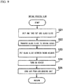
- step S21 shown in FIG. 9 the transfer unit 30 grips and takes out one glass slide 10 from the second washing vessel 40b.
- step S22 the transfer unit 30 transfers the glass slide 10 to a position above the drying vessel 50 which is the transfer destination.
- step S23 the transfer unit 30 puts the griped glass slide 10 between third holders 51 (see FIG. 2 ) of the drying vessel 50 which is the transfer destination.
- step S24 the controller 71 turns on the heater 52 (see FIG. 2 ).
- step S25 the air-sending unit 60 (see FIG. 2 ) sends air to the glass slide 10 held in the drying vessel 50. At this time, the heater 52 warms the air sent from the air-sending unit 60.
- the glass slide 10 receives the air in the drying vessel 50 for a predetermined set time period T7. As a result, the smear staining process onto one glass slide 10 is completed.
- step S9 the transfer unit 30 takes out, from the drying vessel 50, one glass slide 10 for which the staining process has been completed, and transfers the glass slide 10 to the slide storage unit 86. In the manner as described above, the staining operation by the smear preparation apparatus 100 is performed.
- first transfer unit 30a and the second transfer unit 30b perform the transfer of glass slides 10 in parallel, operations performed by the first transfer unit 30a and the second transfer unit 30b in the above-described staining operation are described in detail. Control of the first transfer unit 30a and the second transfer unit 30b in the staining processing operation is performed by the controller 71.
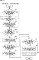
- step S31 shown in FIG. 10 the controller 71 determines whether or not a smeared glass slide 10 is present.
- the first transfer unit 30a transfers, in step S32, the smeared glass slide 10 to the first staining vessel 20a.
- the controller 71 counts the elapsed time period from the time point when the transfer of the glass slide 10 has been completed.
- step S33 shown in FIG. 10 the controller 71 determines whether or not a glass slide 10 for which the set time period T1 has elapsed is present in the first staining vessel 20a.
- the set time period T1 is 120 seconds, for example.
- the process is advanced to step S34, and the first transfer unit 30a transfers, to the second staining vessel 20b, the glass slide 10 of the first staining vessel 20a for which the set time period T1 has elapsed.
- step S35 the controller 71 determines whether or not a glass slide 10 for which the set time period T2 has elapsed is present in the second staining vessel 20b.
- the set time period T2 is 300 seconds, for example.
- step S36 the controller 71 determines whether or not the first transfer unit 30a interferes with the second transfer unit 30b. Specifically, the controller 71 determines whether or not the second transfer unit 30b is present in an interference range which is set to a range that includes the first washing vessel 40a which is the operation overlapping region between the second transfer unit 30b and the first transfer unit 30a. When the second transfer unit 30b is present in the interference range, the controller 71 repeats the determination of step S36, and waits until the second transfer unit 30b comes out of the interference range. When the controller 71 has determined that the first transfer unit 30a does not interfere with the second transfer unit 30b (i.e., the second transfer unit 30b is not present in the interference range), the controller 71 advances the process to step S37.
- step S37 the first transfer unit 30a transfers, to the third staining vessel 20c, the glass slide 10 of the second staining vessel 20b for which the set time period T2 has elapsed.
- step S38 the controller 71 determines whether or not a glass slide 10 for which the set time period T3 has elapsed is present in the third staining vessel 20c.
- the set time period T3 is 300 seconds, for example.
- step S39 the first transfer unit 30a transfers, to the first washing vessel 40a, the glass slide 10 of the third staining vessel 20c for which the set time period T3 has elapsed.
- step S40 the first transfer unit 30a returns to a predetermined waiting position.
- step S33 when the controller 71 has determined in step S31 that the smeared glass slide 10 is not present, the controller 71 advances the process to step S33.
- step S35 when the controller 71 has determined that the glass slide 10 for which the set time period T1 has elapsed is not present in the first staining vessel 20a, the controller 71 advances the process to step S35.
- step S38 when the controller 71 has determined that the glass slide 10 for which the set time period T2 has elapsed is not present in the second staining vessel 20b, the controller 71 advances the process to step S38.
- step S38 when the controller 71 has determined that the glass slide 10 for which the set time period T3 has elapsed is not present in the third staining vessel 20c, the controller 71 advances the process to step S40.
- the controller 71 determines the presence/absence of a glass slide 10 that should be transferred, and when there is no glass slide 10 that should be transferred, the controller 71 returns the first transfer unit 30a to the waiting position. When there is a smeared glass slide 10 or a glass slide 10 for which a set time period has elapsed, the glass slide 10 is sent to the next step.
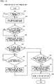
- step S51 shown in FIG. 11 the controller 71 determines whether or not a glass slide 10 for which the set time period T4 has elapsed is present in the first washing vessel 40a.
- the set time period T4 is 15 seconds, for example.
- the process is advanced to step S52.
- step S52 the controller 71 determines whether or not the second transfer unit 30b interferes with the first transfer unit 30a. Similarly to step S36 shown in FIG. 10 , the controller 71 determines whether or not the first transfer unit 30a is present in the interference range. When the controller 71 has determined that the second transfer unit 30b does not interfere with the first transfer unit 30a (i.e., the first transfer unit 30a is not present in the interference range), the controller 71 advances the process to step S53.
- step S53 the second transfer unit 30b transfers, to the fourth staining vessel 20d or the fifth staining vessel 20e, the glass slide 10 of the first washing vessel 40a for which the set time period T4 has elapsed.
- step S54 the controller 71 determines whether or not a glass slide 10 for which the set time period T5 has elapsed is present in the fourth staining vessel 20d or the fifth staining vessel 20e.
- the set time period T5 is 1200 seconds, for example.
- the process is advanced to step S55, and the second transfer unit 30b transfers to the second washing vessel 40b the glass slide 10 for which the set time period T5 has elapsed.
- step S56 the controller 71 determines whether or not a glass slide 10 for which the set time period T6 has elapsed is present in the second washing vessel 40b.
- the set time period T6 is 60 seconds, for example.
- the process is advanced to step S57, and the second transfer unit 30b transfers to the drying vessel 50 the glass slide 10 of the second washing vessel 40b for which the set time period T6 has elapsed.
- step S58 the controller 71 determines whether or not a glass slide 10 for which the set time period T7 has elapsed is present in the drying vessel 50.
- the set time period T7 is 420 seconds, for example.
- the process is advanced to step S59, and the second transfer unit 30b transfers to the slide storage unit 86 the glass slide 10 for which the set time period T7 has elapsed in the drying vessel 50.
- step S60 the second transfer unit 30b returns to a predetermined waiting position.
- the waiting position for the second transfer unit 30b is a predetermined position outside the interference range.
- step S54 when the controller 71 has determined in step S51 that the glass slide 10 for which the set time period T4 has elapsed is not present in the first washing vessel 40a, the controller 71 advances the process to step S54.
- step S54 when the controller 71 has determined in step S54 that the glass slide 10 for which the set time period T5 has elapsed is not present in the fourth staining vessel 20d or the fifth staining vessel 20e, the controller 71 advances the process to step S56.
- step S58 when the controller 71 has determined that the glass slide 10 for which the set time period T6 has elapsed is not present in the second washing vessel 40b, the controller 71 advances the process to step S58.
- step S58 when the controller 71 has determined that the glass slide 10 for which the set time period T7 has elapsed is not present in the drying vessel 50, the controller 71 advances the process to step S60.
- the controller 71 determines the presence/absence of a glass slide 10 that should be transferred, and when there is no glass slide 10 that should be transferred, the controller 71 returns the second transfer unit 30b to the predetermined waiting position.
- the first transfer unit 30a and the second transfer unit 30b perform transfer of the glass slide 10 in parallel.
Landscapes
- Life Sciences & Earth Sciences (AREA)
- Health & Medical Sciences (AREA)
- Chemical & Material Sciences (AREA)
- Biochemistry (AREA)
- General Health & Medical Sciences (AREA)
- Physics & Mathematics (AREA)
- Analytical Chemistry (AREA)
- Pathology (AREA)
- General Physics & Mathematics (AREA)
- Immunology (AREA)
- Engineering & Computer Science (AREA)
- Biomedical Technology (AREA)
- Molecular Biology (AREA)
- Wood Science & Technology (AREA)
- Zoology (AREA)
- Organic Chemistry (AREA)
- Bioinformatics & Cheminformatics (AREA)
- Hematology (AREA)
- Urology & Nephrology (AREA)
- Robotics (AREA)
- Food Science & Technology (AREA)
- Medicinal Chemistry (AREA)
- Microbiology (AREA)
- Genetics & Genomics (AREA)
- General Engineering & Computer Science (AREA)
- Sustainable Development (AREA)
- Biotechnology (AREA)
- Virology (AREA)
- Cell Biology (AREA)
- Sampling And Sample Adjustment (AREA)
- Investigating Or Analysing Biological Materials (AREA)
- Automatic Analysis And Handling Materials Therefor (AREA)
Abstract
Description
- The present invention relates to a smear preparation apparatus and a smear preparation method.
-
PATENT LITERATURE 1 discloses a smear preparation apparatus provided with: a staining basket which accommodates a plurality of glass slides; a transfer mechanism for hanging and moving the staining basket; and a liquid storage container for storing a staining liquid therein. In the smear preparation apparatus ofPATENT LITERATURE 1, the transfer mechanism immerses the staining basket accommodating a plurality of glass slides, into a staining liquid in the liquid storage container, whereby the plurality of glass slides are stained at one time. - [PTL 1] Japanese Laid-Open Patent Publication No.
H10-90144 - The smear preparation apparatus of
PATENT LITERATURE 1 has the following problems. That is, since a plurality of glass slides are stained at one time in the staining basket, and staining operation is not performed until a plurality of glass slides are accumulated in the staining basket, the time period (turn around time) from the time when an order of smear preparation is generated until the smear is prepared becomes long. In addition, there is also a problem that since staining is performed by using the staining basket, the size of the apparatus is increased. - A smear preparation apparatus according to a first aspect of the present invention includes: a staining vessel for storing a staining liquid therein so as to allow a plurality of glass slides each having a sample smeared thereon to be immersed therein; and a transfer unit for holding and transferring each glass slide, wherein the staining vessel includes a plurality of first holders configured to hold the glass slides, the staining vessel is configured such that a plurality of glass slides held by a plurality of the first holders are immersed in the stored staining liquid, and the transfer unit is configured to put in/take out the glass slides one by one with respect to a plurality of the first holders of the staining vessel.
- A smear preparation method according to a second aspect of the present invention includes: storing a staining liquid so as to immerse, in a staining vessel including a plurality of first holders configured to hold glass slides each having a sample smeared thereon, a plurality of the glass slides held by a plurality of the first holders; gripping and transferring, by a transfer unit, each glass slide to the staining vessel; and putting in/taking out the glass slides one by one, by the transfer unit, with respect to a plurality of the first holders of the staining vessel.
- According to the present invention, the time period necessary for a staining process is shortened, and the apparatus can be downsized.
-
- [
FIG. 1] FIG. 1 is a schematic diagram showing the outline of a smear preparation apparatus according to one embodiment. - [
FIG. 2] FIG. 2 is a perspective view showing specific configurations of a staining vessel and a transfer unit of the smear preparation apparatus according to one embodiment. - [
FIG. 3] FIG. 3 is a schematic top view of the staining vessel and the washing vessel shown inFIG. 2 . - [
FIG. 4] FIG. 4 is an enlarged longitudinal cross-sectional view taken along the line IV-IV shown inFIG. 3 . - [
FIG. 5] FIG. 5 is a partial sectional view taken along the line V-V shown inFIG. 4 . - [
FIG. 6] FIG. 6 is a schematic plan view for explaining the overall configuration of the smear preparation apparatus according to one embodiment. - [
FIG. 7] FIG. 7 is a flow chart for explaining the operation performed by the smear preparation apparatus according to one embodiment. - [
FIG. 8] FIG. 8 is a flow chart of a staining process and a washing process shown inFIG. 7 . - [
FIG. 9] FIG. 9 is a flow chart of a drying process performed in a drying vessel shown inFIG. 7 . - [
FIG. 10] FIG. 10 is a flow chart for explaining the operation performed by a first transfer unit. - [
FIG. 11] FIG. 11 is a flow chart for explaining the operation performed by a second transfer unit. - Hereinafter, embodiments are described with reference to the drawings.
- With reference to
FIG. 1 to FIG. 6 , asmear preparation apparatus 100 according to the present embodiment is described. - The
smear preparation apparatus 100 is an apparatus for automatically creating a smear by performing, on asampling glass slide 10 having a sample smeared thereon, a smearing process of smearing a sample, and a process of staining theglass slide 10 having the sample smeared thereon. The sample is blood, for example. - As shown in
FIG. 1 , thesmear preparation apparatus 100 includes astaining vessel 20 and atransfer unit 30. - The
staining vessel 20 is formed in a container shape, and can store therein a stainingliquid 11 so as to allow aglass slide 10 having a sample smeared thereon to be immersed therein. Thestaining vessel 20 is formed in a container shape, and can store a stainingliquid 11 therein. Thestaining vessel 20 includes a plurality offirst holders 21 configured to hold theglass slides 10. Thefirst holders 21form insertion regions 12 into each of which aglass slide 10 can be inserted. A staining process is performed by immersing, in thestaining liquid 11 for a predetermined time period, theglass slides 10 held by thefirst holders 21 in thestaining vessel 20. - As the configuration of the plurality of the
first holders 21 for forming theinsertion regions 12, a variety of configurations can be employed. For example, the plurality of thefirst holders 21 may be members arranged with an interval therebetween in a predetermined direction, as shown inFIG. 1 . In this case, aninsertion region 12 can be formed between adjacentfirst holders 21. Other than this, thefirst holders 21 may each be configured by horizontally disposing, at a predetermined height position in thestaining vessel 20, a plate member (not shown) provided with a slit-like first holder into which aglass slide 10 can be inserted, for example. In this case, aninsertion region 12 can be formed in the slit-like first holder. It is sufficient that the number offirst holders 21 is a plural number, and the number offirst holders 21 can be set in accordance with the configuration of the apparatus. - The
transfer unit 30 is provided in order to grip and transfer aglass slide 10 having a sample smeared thereon. Thetransfer unit 30 is configured to put in/take out theglass slides 10 one by one with respect to a plurality of thefirst holders 21 of thestaining vessel 20. That is, thetransfer unit 30 can set theglass slides 10 one by one into theinsertion regions 12 of thefirst holders 21. - Also as the configuration of the
transfer unit 30 for putting in/taking out theglass slides 10 one by one with respect to the respectivefirst holders 21, various configurations can be employed. For example, as shown inFIG. 1 , thetransfer unit 30 is a 3-axis orthogonal robot that can move in the horizontal direction and the up-down direction (Z direction), and that includes ahand 31 for grasping aglass slide 10. Thetransfer unit 30 may be able to move only one of the horizontal direction and the up-down direction, and thestaining vessel 20 may be able to move in the other of the horizontal direction and the up-down direction. For example, thehand 31 may be realized as an open/close mechanism that can nip and grip aglass slide 10, or a suction mechanism that suctions and grips a predetermined portion of aglass slide 10. - With the above configuration, the
transfer unit 30 sets theglass slides 10 one by one to thefirst holders 21 of thestaining vessel 20 in which thestaining liquid 11 is stored, whereby the staining process for theglass slides 10 can be performed. Accordingly, at the time point when individual glass slides 10 get ready, the staining process can be quickly started for theglass slides 10 one by one. Thus, differently from a configuration in which a plurality of glass slides set in a staining basket are stained at one time, there is no need to wait for the staining operation to be started until a plurality ofglass slides 10 are accumulated in the staining basket. As a result, the time period necessary for the staining process can be shortened. - Since the plurality of the
first holders 21 use thestaining liquid 11 in common, the staining and washing steps can be simplified, compared with a case where staining is performed by using a slide container that holds a single glass slide. The reason is as follows. In a case where staining is performed by using a slide container that holds a single glass slide, the slide container needs to be washed each time one glass slide is stained, and thus, pouring and discharging of the staining liquid and the washing liquid need to be performed each time. However, in the case of the present embodiment, a plurality of glass slides held by a plurality of thefirst holders 21 use thestaining liquid 11 in common, and thus, pouring and discharging of the staining liquid and the washing liquid need not be performed each time a slide is stained, and thus, steps can be simplified. In addition, in a case where staining is performed by using a slide container that holds a single glass slide, staining is performed by putting a small amount of the staining liquid into a slide container which is small compared with thestaining vessel 20 of the present embodiment. In the case of the present embodiment, a configuration is employed in which a plurality of glass slides held by a plurality of the first holders are immersed in the stored staining liquid, and thus, variation in the staining degree among the plurality of glass slides depending on the state of the slide container such as due to smudges can be suppressed. - Since the
transfer unit 30 is configured to put in/take out theglass slides 10 one by one with respect to a plurality of thefirst holders 21, there is no need to move a large member such as a staining basket that can accommodate a plurality ofglass slides 10. Accordingly, thetransfer unit 30 and thestaining vessel 20 can be downsized, and the space necessary for moving thetransfer unit 30 can be reduced. As a result, according to thesmear preparation apparatus 100, the time period necessary for the staining process can be shortened and the apparatus can be downsized. - Hereinafter, with reference to
FIG. 2 and thereafter, specific configurations of a preferred embodiment of thesmear preparation apparatus 100 shown inFIG. 1 are described. - As shown in
FIG. 2 , thesmear preparation apparatus 100 may further include awashing vessel 40, a dryingvessel 50, and an air-sendingunit 60. Thetransfer unit 30 includes afirst transfer unit 30a and asecond transfer unit 30b. Thesmear preparation apparatus 100 includes: afluid circuit unit 70 configured to respectively supply/discharge the stainingliquid 11 and awashing liquid 13 to/from the stainingvessel 20 and thewashing vessel 40; and acontroller 71 configured to control thetransfer unit 30, the air-sendingunit 60, and the like.
Thecontroller 71 is a computer that includes a CPU and a memory not shown. - In the following, the width direction of the
glass slide 10 to be inserted in the staining vessel 20 (i.e., the width direction of the insertion region 12) is defined as an X direction, and the arrangement direction of the glass slides 10 to be inserted in the staining vessel 20 (that is, the thickness direction of the insertion region 12) is defined as a Y direction. The up-down direction which is the direction along which theglass slide 10 is inserted is defined as a Z direction. - Preferably, the staining
vessel 20 includes afirst staining vessel 20a for storing a first staining liquid therein, and asecond staining vessel 20b for storing a second staining liquid therein, and thestaining vessel 20 includes aseparation member 14a for separating thefirst staining vessel 20a and thesecond staining vessel 20b from each other.FIG. 2 shows an example in which thestaining vessel 20 includes fivestaining vessels 20, i.e., thefirst staining vessel 20a to afifth staining vessel 20e. Thefirst staining vessel 20a, thesecond staining vessel 20b, and thethird staining vessel 20c are integrally formed while being separated from one another byseparation members 14a. Furthermore, thefourth staining vessel 20d and thefifth staining vessel 20e are integrally formed while being separated from each other by aseparation member 14a. Since thefirst staining vessel 20a to thefifth staining vessel 20e are integrally formed while being separated from one another by theseparation members 14a in this manner, even in a case where the staining process is performed by using a plurality of kinds of thestaining liquids 11, thefirst staining vessel 20a to thefifth staining vessel 20e can be integrally formed as a whole. As a result, when compared with a case where each staining vessel is individually formed, the configuration of the apparatus can be simplified. - The
washing vessel 40 is provided in order to store therein thewashing liquid 13 so as to allow the glass slides 10 to be immersed therein. As the configuration of thewashing vessel 40, a configuration common to thestaining vessel 20 can be employed. That is, thewashing vessel 40 includes a plurality ofsecond holders 41 each similar to thefirst holder 21, and can hold the glass slides 10 in thesecond holders 41 configured to hold glass slides 10. Thetransfer unit 30 is configured to put in/take out the glass slides 10 one by one with respect to the plurality ofsecond holders 41 of thewashing vessel 40. Accordingly, in a washing process step after the staining process, at the time point when individual glass slides 10 get ready, the washing process can be quickly started for the glass slides 10 one by one. As a result, there is no need to wait for the washing operation to be started until a plurality of glass slides 10 are accumulated. Thus, the time period necessary for the washing process can be shortened. - As shown in
FIG. 3 , thewashing vessel 40 includes afirst washing vessel 40a and asecond washing vessel 40b separated by theseparation members 14a. In addition, fivestaining vessels 20 of thefirst staining vessel 20a to thefifth staining vessel 20e, and twowashing vessels 40 of thefirst washing vessel 40a and thesecond washing vessel 40b are integrally formed in asingle structure 14. - That is, the
single structure 14 includes a large number offirst holders 21 andsecond holders 41 arranged in the Y direction. Thesingle structure 14 is provided with a total of six plate-like separation members 14a that separate the vessels from one another at predetermined positions in the Y direction. Via theseseparation members 14a, fivestaining vessels 20 and twowashing vessels 40 are integrally formed so as to be arranged in the Y direction in thesingle structure 14. The numbers of thestaining vessels 20 and thewashing vessels 40 may be set to numbers in accordance with the number of steps of the staining process. Thesingle structure 14 is preferably formed from a resin material or the like that has chemical resistance and that is easy to be washed. - The five
staining vessels 20 and the twowashing vessels 40 are separated from one another by theseparation members 14a, and thus, do not allow liquid to flow thereamong. Each of thestaining vessels 20 and thewashing vessels 40 are provided with asupply port 15a for supplying a liquid, and with adischarge port 15b for discharging a liquid, individually. Accordingly, thestaining vessels 20 and thewashing vessels 40 can each store thestaining liquid 11 or thewashing liquid 13 of a kind different from one another. In the staining process for theglass slide 10, a plurality of kinds of thestaining liquids 11 are used. All of the stainingliquid 11 in each vessel is replaced after a previously-set predetermined number of glass slides 10 have been stained. - The
staining vessels 20 and thewashing vessels 40 are arranged, in the order from the Y2 direction side, thefirst staining vessel 20a, thesecond staining vessel 20b, thethird staining vessel 20c, thefirst washing vessel 40a, thefourth staining vessel 20d, thefifth staining vessel 20e, and thesecond washing vessel 40b. The glass slides 10 are transferred into the vessels in the order starting at thefirst staining vessel 20a at the Y2 direction side, and are immersed for a predetermined set time period in thestaining liquid 11 or thewashing liquid 13 stored in the corresponding vessels, thereby being processed. The set time period for the process performed in each vessel is different depending on the kind of the stainingliquid 11 or thewashing liquid 13 stored in the vessel, and is set to a time period necessary for processing the glass slides 10. - The number of
first holders 21 of each stainingvessel 20 and the number ofsecond holders 41 in each washing vessel 40 (that is, the number of insertion regions 12) are each set to a number corresponding to the set time period for processing the glass slides 10. The number offirst holders 21 and the number ofsecond holders 41 are preferably determined in accordance with the carry-in time interval of the glass slides 10 as a specification of thesmear preparation apparatus 100, and the length of the set time period that is set for processing the glass slides 10 in each vessel. That is, when the carry-in time interval is defined as A and a set time period for a vessel is defined as B, thefirst holders 21 and thesecond holders 41 are provided such that at least B/A glass slides 10 can be inserted in that vessel. Preferably, thefirst holders 21 and thesecond holders 41 are provided by a number greater than B/A. - In a case of a process step having a long set time period, an identical kind of the staining
liquid 11 may be stored in a plurality ofstaining vessels 20 and the process of an identical step may be shared by the plurality ofstaining vessels 20. In the present embodiment, thefourth staining vessel 20d and thefifth staining vessel 20e are the staining vessels that store an identical kind of the stainingliquid 11 and that perform the process of an identical step. In this case, the total number of theinsertion regions 12 of thefourth staining vessel 20d and thefifth staining vessel 20e is preferably set to be B/A or greater. The glass slides 10 are transferred to either one of thefourth staining vessel 20d and thefifth staining vessel 20e, and are not transferred to the other of thefourth staining vessel 20d and thefifth staining vessel 20e. With this configuration, even when the stainingliquid 11 of one of thefourth staining vessel 20d and thefifth staining vessel 20e is replaced, the staining process can be continued in the other of thefourth staining vessel 20d and thefifth staining vessel 20e. - Here, when the number of
first holders 21 becomes large, the volume of thestaining vessel 20 is increased, accordingly, and the amount of the staining liquid stored therein is also increased. Thus, the time period necessary for replacing the stainingliquid 11 is increased. Meanwhile, in the present invention, since a plurality of staining vessels (thefourth staining vessel 20d and thefifth staining vessel 20e) that perform an identical step are provided, increase in the waiting time for replacing the stainingliquid 11 can be suppressed. - With reference back to
FIG. 2 , the dryingvessel 50 is disposed so as to be aligned with thestaining vessels 20 and thewashing vessels 40 in the arrangement direction Y thereof. The dryingvessel 50 is adjacent to thestructure 14. The dryingvessel 50 is provided in order to dry the glass slides 10 having been subjected to the staining process and the washing process. The dryingvessel 50 includes a plurality ofthird holders 51 configured to hold glass slides 10. The plurality ofthird holders 51 have open upper ends, and are arranged with an interval therebetween in the Y direction. Thethird holders 51 can hold the glass slides 10 one by one with an interval therebetween. Inside the dryingvessel 50, an air passage (not shown) is provided, and the air passage is connected to the air-sendingunit 60. Thetransfer unit 30 is configured to put in/take out the glass slides 10 one by one with respect to thethird holders 51 of the dryingvessel 50. - The air-sending
unit 60 is provided in order to send air to the glass slides 10 held in the dryingvessel 50. The air-sendingunit 60 includes an electric fan, for example, and can forcibly send air into the air passage inside the dryingvessel 50. The air-sendingunit 60 can dry the glass slides 10 by continuously sending air, for a predetermined time period, to the glass slides 10 set in thethird holders 51 inside the dryingvessel 50. Since the dryingvessel 50 and the air-sendingunit 60 are provided, the glass slides 10 having been subjected to the staining process can be speedily dried, and thus, the time period necessary for the staining process can be shortened. Similarly to thestaining vessel 20 and thewashing vessel 40, theglass slide 10 can be inserted and pulled out with respect to thethird holders 51 by thetransfer unit 30, and thus, the configuration of the apparatus can be simplified. - Preferably, the
smear preparation apparatus 100 includes aheater 52 which warms the air sent from the air-sendingunit 60. Theheater 52 is located between the air-sendingunit 60 and the dryingvessel 50. The air sent from the air-sendingunit 60 receives heat when passing through theheater 52, and then is sent in a state of warm air having an increased temperature, to the air passage in the dryingvessel 50. Accordingly, the glass slides 10 having been subjected to the staining process can be more speedily dried, and thus, the time period necessary for the staining process can be further shortened. - The
first transfer unit 30a and thesecond transfer unit 30b of thetransfer unit 30 are both disposed above (Z1 direction) thestaining vessels 20 and thewashing vessels 40. Thefirst transfer unit 30a and thesecond transfer unit 30b can each be moved in the horizontal direction (i.e., X direction and Y direction) by amovement mechanism 32. - The
movement mechanism 32 includes: aY axis rail 33a and aY axis slider 33b in the Y direction; anX axis rail 34a and anX axis slider 34b in the X direction; and aY axis motor 33c and anX axis motor 34c. As each of theX axis motor 34c and theY axis motor 33c, a stepping motor or a servo motor can be employed, for example. - The
Y axis rail 33a linearly extends in the Y direction, and is fixed to the lower face of thesupport member 33d. Thesupport member 33d is, for example, a ceiling portion or a support beam member of the housing of thesmear preparation apparatus 100. TheY axis slider 33b is mounted to the lower face side (Z2 direction side) of theY axis rail 33a, and can move along theY axis rail 33a. TheY axis motor 33c causes theY axis slider 33b to move in the Y direction via a transmission mechanism not shown. As the transmission mechanism, a belt pulley mechanism or a rack-and-pinion mechanism can be employed, for example. - The
X axis rail 34a linearly extends in the X direction and is fixed to the lower face of theY axis slider 33b. TheX axis slider 34b is mounted to the lower face side (Z2 direction side) of theX axis rail 34a, and can move along theX axis rail 34a. TheX axis motor 34c causes theX axis slider 34b to move in the X direction via a transmission mechanism not shown. - The
Y axis slider 33b, theX axis rail 34a, theX axis slider 34b, theX axis motor 34c, and theY axis motor 33c are each provided in a pair. At the lower face sides of the pair of theX axis sliders 34b, thefirst transfer unit 30a and thesecond transfer unit 30b are mounted, respectively. Accordingly, thefirst transfer unit 30a and thesecond transfer unit 30b can move in the X direction independently of each other, along the separate X axis rails 34a. In addition, thefirst transfer unit 30a and thesecond transfer unit 30b can move in the Y direction independently of each other, along the commonY axis rail 33a. - The configuration of the
first transfer unit 30a and the configuration of thesecond transfer unit 30b are common to each other. Thefirst transfer unit 30a and thesecond transfer unit 30b each include aZ axis motor 35a and atransmission mechanism 35b for raising and lowering thehand 31. TheZ axis motor 35a causes thehand 31 to be raised and lowered via thetransmission mechanism 35b. As thetransmission mechanism 35b, a belt pulley mechanism or a rack-and-pinion mechanism can be employed, for example. - The
hand 31 can grasp oneglass slide 10.FIG. 2 shows an example of a configuration in which aglass slide 10 is nipped and grasped in the thickness direction thereof by a pair of graspingplates 31a. As shown inFIG. 5 , the pair of graspingplates 31a can nip aglass slide 10 by being in contact with the front surface side and the rear surface side of theglass slide 10. Of one graspingplate 31 a, the graspingplate 31 a at the rear surface side (Y1 direction side) can move in the thickness direction of theglass slide 10. Moving of thegrasping plate 31a can be performed by using an actuator such as an air cylinder, a motor, or a solenoid, for example, but illustration and description thereof are omitted. Thehand 31 may be configured to nip and grasp aglass slide 10 in the width direction. - Preferably, a
cushion member 31b formed from a flexible material such as rubber is provided to thegrasping plate 31a at the front surface side (Y2 direction side) of theglass slide 10. Accordingly, when the graspingplate 31 a is to grasp theglass slide 10, even if thegrasping plate 31a comes into contact with a print provided at the front surface of theglass slide 10, readability of the print is suppressed from being impaired. A cushion member similar to thecushion member 31 b may be provided to thegrasping plate 31a at the rear surface side. - With reference back to
FIG. 2 , thefirst transfer unit 30a can move to positions above thefirst staining vessel 20a, thesecond staining vessel 20b, thethird staining vessel 20c, and thefirst washing vessel 40a on the Y2 direction side. Therefore, thefirst transfer unit 30a can insert and pull out the glass slides 10 one by one with respect to theinsertion regions 12 of each of thefirst staining vessel 20a, thesecond staining vessel 20b, thethird staining vessel 20c, and thefirst washing vessel 40a. - The
second transfer unit 30b can move among positions above thesecond washing vessel 40b, thefifth staining vessel 20e, thefourth staining vessel 20d, and thefirst washing vessel 40a on the Y1 direction side, a position above the dryingvessel 50, and a transfer position to a slide storage unit 86 (seeFIG. 6 ) described later. Therefore, thesecond transfer unit 30b can insert and pull out the glass slides 10 one by one with respect to theinsertion regions 12 of each of thefourth staining vessel 20d, thefifth staining vessel 20e, thefirst washing vessel 40a, and thesecond washing vessel 40b. - The
first transfer unit 30a and thesecond transfer unit 30b can transfer, in parallel, different glass slides 10, respectively. The operation range of thefirst transfer unit 30a and the operation range of thesecond transfer unit 30b overlap each other at thefirst washing vessel 40a, and in thefirst washing vessel 40a, theglass slide 10 is handed over. The handing over position may be a position other than thefirst washing vessel 40a. - Next, details of configurations of the
staining vessel 20 and thewashing vessel 40 in a preferable embodiment are described. As described above, the structures ofindividual staining vessels 20 andindividual washing vessels 40 are basically the same, except for the number offirst holders 21 or the number ofsecond holders 41. Thus, in the following, the structure of onestaining vessel 20 is described in detail. - As shown in
FIG. 4 , the stainingvessel 20 includes anupper face opening 22a that allows aglass slide 10 to be inserted therethrough, and theglass slide 10 can be inserted or pulled out in the up-down direction Z through theupper face opening 22a. In thestaining vessel 20, the cross-sectional shape along the width direction (X direction) of the glass slide 10 (i.e., insertion region 12) is substantially in a T-shape. In the thickness direction (Y direction) of theglass slide 10, the stainingvessel 20 basically extends while having the cross-sectional shape shown inFIG. 4 except for a bottom portion thereof. - Here, the shape of the
glass slide 10 is described. Theglass slide 10 is a rectangular plate-like member. Theglass slide 10 includes, in a center portion in the longitudinal direction thereof, astaining region 10a where a sample is smeared. In addition, theglass slide 10 includes afrost part 10b serving as a printing region for sample information, on the front surface of one end portion in the longitudinal direction of theglass slide 10. Thefrost part 10b is a portion that has been processed to be printable by being coated with a resin material or the like. On thefrost part 10b, a sample number, a date, a barcode or two-dimensional code, and the like can be printed. Theglass slide 10 is inserted into thestaining vessel 20 with thefrost part 10b located at the upper side, so as to prevent thefrost part 10b from being immersed in thestaining liquid 11. - Preferably, in the width direction (X direction) of the
glass slide 10, aninternal dimension 22e of anupper portion 22b of thestaining vessel 20 is greater than aninternal dimension 22f of alower portion 22c of thestaining vessel 20. Here, alength 22d (seeFIG. 3 ) in the Y direction of thestaining vessel 20 is the same between theupper portion 22b and thelower portion 22c, and the horizontal cross-sectional area is determined depending on the width (internal dimension) in the X direction. Thus, the stainingvessel 20 is formed such that the horizontal cross-sectional area in theupper portion 22b is greater than the horizontal cross-sectional area in thelower portion 22c. This can suppress the variation in the liquid level of the stainingliquid 11 in theupper portion 22b, the variation being caused by decrease of the staining liquid and associated with putting in/taking out theglass slide 10. - That is, the supply amount of the staining
liquid 11 is set such that aliquid surface position 11 a is above thestaining region 10a of theglass slide 10 and is located below thefrost part 10b, in a state where theglass slide 10 is inserted. However, theliquid surface position 11 a goes up or down within avariation range 11b, in accordance with the number of glass slides 10 inserted in thestaining vessel 20. Therefore, by setting the horizontal cross-sectional area in theupper portion 22b to be relatively large, it is possible to decrease thevariation range 11b associated with increase and decrease of the number of inserted glass slides 10. As a result, even when the number of glass slides 10 varies, thestaining region 10a can be reliably stained. On the other hand, if the horizontal cross-sectional area of thelower portion 22c is also set to be large, the stored amount of the stainingliquid 11 for locating theliquid surface position 11a at a predetermined height is increased, and thus, the consumption amount of the stainingliquid 11 is increased. Therefore, by setting the horizontal cross-sectional area in thelower portion 22c to be relatively small, it is possible to suppress unnecessary increase of the consumption amount of the stainingliquid 11. - Preferably, the staining
vessel 20 includes aninclined portion 23 between theupper portion 22b and thelower portion 22c in the width direction X of theglass slide 10. Theinclined portion 23 is inclined in a direction along which the width is reduced toward thelower portion 22c. Specifically, theinclined portion 23 is linearly inclined such that the width (internal dimension) between both sides of theinsertion region 12 is reduced toward the lower side (Z2 direction). Theinclined portion 23 may be inclined in a curved manner. - Due to the
inclined portion 23, even when the position in the X direction of theglass slide 10 is slightly shifted during insertion of theglass slide 10, theglass slide 10 can be reliably inserted into thelower portion 22c. - The
lower portion 22c includes alateral support portion 24 and abottom portion 25. Thelateral support portion 24 is connected, at the upper end thereof, to the lower end of theinclined portion 23, and has a width (internal dimension) substantially equal to awidth 10c of theglass slide 10, in the width direction X of theglass slide 10. Thelateral support portion 24 has a function of supporting side end faces of theglass slide 10. - Between the
lateral support portion 24 and thebottom portion 25, alower support portion 24a having a step-like shape is present. Thelower support portion 24a is located at an upper position relative to the inner bottom face of thebottom portion 25, and protrudes inwardly from the inner face of thelateral support portion 24. Thelower support portion 24a is the lower end of theinsertion region 12, and thelower support portion 24a can support the lower end face of the insertedglass slide 10. Theglass slide 10 is supported at a position that is above and separated from the inner bottom face of thebottom portion 25 of thestaining vessel 20. - As shown in
FIG. 5 , thebottom portion 25 of thestaining vessel 20 includes asupply port 15a and adischarge port 15b. The inner bottom face of thebottom portion 25 is formed as an inclined surface, and thedischarge port 15b is located at the lowest position in thebottom portion 25. Thesupply port 15a is located at an upper position relative to thedischarge port 15b. Accordingly, when the stainingliquid 11 is discharged, the stainingliquid 11 gathers at thedischarge port 15b, and thus, the stainingliquid 11 can be suppressed from remaining in thestaining vessel 20. - With reference back to
FIG. 4 , preferably, the plurality of thefirst holders 21 are provided in pairs at both end portions in the width direction X of theinsertion region 12. Each pair offirst holders 21 are not provided at the center portion in the width direction X of theinsertion region 12, and inner end portions in the X direction of the pair offirst holders 21 overlap, in the Y direction, both end portions in the X direction of theglass slide 10 inserted in theinsertion region 12. These overlapping portions are at the outer sides relative to thestaining region 10a of theglass slide 10. Therefore, each pair offirst holders 21 do not come into contact with thestaining region 10a of theglass slide 10 inserted in theinsertion region 12, and can respectively support, in the Y direction, both end portions in the X direction of theglass slide 10. - As shown in
FIG. 5 , the plurality of thefirst holders 21 are arranged with aninterval 12a therebetween, theinterval 12a corresponding to theinsertion region 12 in the thickness direction Y of theinsertion region 12. Thefirst holders 21 can support, from both sides in the Y direction, both end portions in the X direction of theglass slide 10. - Preferably, in the thickness direction (Y direction) of the
glass slide 10, at least a part of thefirst holder 21 is tapered toward the upper end thereof. That is, thefirst holder 21 includes a taperedportion 21a which is tapered toward the upper end thereof in the Y direction. The taperedportion 21 a functions as a guide in the Y direction when theglass slide 10 is to be inserted. Due to the taperedportion 21 a, even when the position in the Y direction of theglass slide 10 is slightly shifted during insertion of theglass slide 10, theglass slide 10 can be reliably inserted into theinsertion region 12. - Next, the path along which the
glass slide 10 is transferred by thetransfer unit 30 according to a preferable embodiment is described. - As shown in
FIG. 3 , preferably, thetransfer unit 30 transfers theglass slide 10 by making a detour such that theglass slide 10 does not pass above thefirst holders 21. In the example shown inFIG. 3 , thetransfer unit 30 transfers theglass slide 10 along thepath 27c. That is, since thefirst holders 21 are disposed side by side in the Y direction, thetransfer unit 30 transfers the graspedglass slide 10 in the Y direction, at a position shifted in the X direction relative to thefirst holders 21. Then, thetransfer unit 30 aligns the position in the Y direction of the graspedglass slide 10 with the position in the Y direction of thefirst holders 21 which is the transfer destination, and then moves theglass slide 10 in the X direction, to locate theglass slide 10 above theinsertion region 12. Thus, even if the stainingliquid 11 attached to theglass slide 10 drops during the transfer of theglass slide 10, the droplets of the droppedstaining liquid 11 can be prevented from attaching to thefrost part 10b of anotherglass slide 10. As a result, portions other than the staining region of theglass slide 10 can be prevented from being smudged by the stainingliquid 11. - The
staining vessel 20 includes atransfer region 27 adjacent to thefirst holders 21, in the width direction X of theglass slide 10. Thetransfer unit 30 transfers theglass slide 10 such that theglass slide 10 passes above thetransfer region 27. - As shown in
FIG. 4 , thetransfer region 27 is present at both sides in the X direction relative to a pair offirst holders 21. Thetransfer regions 27 at both sides respectively have awidth 27a and awidth 27b which are each greater than thewidth 10c of theglass slide 10. In thetransfer regions 27, the stainingliquid 11 is stored similarly to theinsertion region 12. In the example shown nFIG. 4 , thetransfer regions 27 are formed, in theupper portion 22b having theinternal dimension 22e, by a protrudingportion 26 formed so as to protrude in the X direction from theinclined portion 23. In other words, thetransfer regions 27 are formed as a result of theinternal dimension 22e of theupper portion 22b being made greater than theinternal dimension 22f of thelower portion 22c. As shown inFIG. 3 , thetransfer unit 30 transfers theglass slide 10 along thepath 27c that passes above thetransfer region 27. Thus, the stainingliquid 11 attached to the graspedglass slide 10 is prevented from dropping to the outside of thestaining vessel 20. That is, thetransfer region 27 of thestaining vessel 20 functions as a receiver of the stainingliquid 11 that drops during transfer of theglass slide 10. As a result, decrease of the stainingliquid 11 in thestaining vessel 20 can be suppressed, and smudging of the outside of thestaining vessel 20 by the droppedstaining liquid 11 can be inhibited. - More preferably, the staining
vessel 20 and thewashing vessel 40 are adjacent to each other. In addition, thetransfer unit 30 makes a detour such that theglass slide 10 does not pass above thefirst holders 21 of thestaining vessel 20 and thesecond holders 41 of thewashing vessel 40, and transfers theglass slide 10 along the direction in which thestaining vessel 20 and thewashing vessel 40 are adjacent to each other. - In the example shown in
FIG. 3 , the stainingvessel 20 and thewashing vessel 40 are adjacent to each other in the Y direction, and thetransfer unit 30 performs transfer above thetransfer region 27 along thepath 27c extending along the Y direction. Thus, even when thetransfer unit 30 is caused to make a detour, thetransfer unit 30 is simply caused to move along the Y direction in which thestaining vessel 20 and thewashing vessel 40 are adjacent to each other. Thus, increase in the space necessary for causing thetransfer unit 30 to make a detour can be suppressed. - With reference to
FIG. 6 , other configurations of thesmear preparation apparatus 100 are described. - The components such as the
staining vessel 20 and thetransfer unit 30 shown inFIG. 2 to FIG. 5 are configured as astaining unit 81 shown inFIG. 6 . In a preferable embodiment, thesmear preparation apparatus 100 further includes aslide supply unit 82, aprinting unit 83, asmear unit 84, a dryingunit 85, and theslide storage unit 86. - The
slide supply unit 82 stores a large number of unused glass slides 10 not yet subjected to sample smearing. Theslide supply unit 82 can supply theprinting unit 83 with glass slides 10 one by one that have not yet been subjected to smearing. - The
printing unit 83 can print various kinds of information such as sample information onto thefrost part 10b (seeFIG. 4 ) which is the printing region of theglass slide 10. Theprinting unit 83 can transfer the printedglass slide 10 to thesmear unit 84. - The
smear unit 84 can suction a sample by means of a sample suction mechanism not shown, and can smear the sample on thestaining region 10a (seeFIG. 4 ) of theglass slide 10 sent from theprinting unit 83. Thesmear unit 84 can transfer theglass slide 10 having been subjected to the smearing process, to the dryingunit 85. - The drying
unit 85 has a function of receiving from thesmear unit 84 theglass slide 10 having the sample smeared thereon, and of drying thestaining region 10a. - As described above, in the
staining unit 81, eachglass slide 10 having a sample smeared thereon and having been dried in the dryingunit 85 is subjected to the staining process and the washing process in each of thestaining vessel 20 and thewashing vessel 40. Thereafter, when a drying step is performed in the dryingvessel 50 and staining of theglass slide 10 is completed, the stainedglass slide 10 is sent to theslide storage unit 86. Transfer of theglass slide 10 among these units is performed by the transfer unit 30 (seeFIG. 2 ). - The
slide storage unit 86 has a function of storing stained glass slides 10. - With this configuration, the
smear preparation apparatus 100 can automatically create a smear by performing processes of printing to theglass slide 10, smearing of a sample, and staining. - With reference to
FIG. 2 ,FIG. 3 , andFIG. 6 toFIG. 9 , staining operation performed by thesmear preparation apparatus 100 is described. Control of thesmear preparation apparatus 100 is performed by thecontroller 71. - First, in step S1 shown in
FIG. 7 , the stainingliquid 11 and thewashing liquid 13 are stored in thestaining vessels 20 and thewashing vessels 40, respectively. To each stainingvessel 20 and eachwashing vessel 40, the fluid circuit unit 70 (seeFIG. 2 ) supplies thestaining liquid 11 and thewashing liquid 13 via thesupply ports 15a (seeFIG. 3 ), respectively. - In step S2, the
transfer unit 30 transfers the glass slides 10 one by one to thefirst staining vessel 20a (seeFIG. 3 ), and a staining process is performed in thefirst staining vessel 20a. - Specifically, in step S11 shown in
FIG. 8 , thetransfer unit 30 grips and takes out one smearedglass slide 10. In step S12, thetransfer unit 30 transfers theglass slide 10 to a position above thefirst staining vessel 20a which is the transfer destination. At this time, thetransfer unit 30 transfers theglass slide 10 along thepath 27c shown inFIG. 3 . In step S13, thetransfer unit 30 puts the gripedglass slide 10 betweenfirst holders 21 of thefirst staining vessel 20a which is the transfer destination. The operation shown inFIG. 8 is common in steps S3 to S7 described later, except that the take-out position and the transfer destination of theglass slide 10 are different. - In the
first staining vessel 20a, afirst staining liquid 11 is stored. In this state, theglass slide 10 is immersed in thefirst staining liquid 11 for a predetermined set time period T1, whereby the staining process is performed. - With reference back to
FIG. 7 , in step S3, thetransfer unit 30 transfers theglass slide 10 to thesecond staining vessel 20b (seeFIG. 3 ), and a staining process is performed in thesecond staining vessel 20b. Through steps S11 to S13 shown inFIG. 8 , theglass slide 10 is taken out of thefirst staining vessel 20a by thetransfer unit 30, and is put betweenfirst holders 21 of thesecond staining vessel 20b. Theglass slide 10 is immersed in asecond staining liquid 11 stored in thesecond staining vessel 20b, for a predetermined set time period T2. - In step S4, the
transfer unit 30 transfers theglass slide 10 to thethird staining vessel 20c (seeFIG. 3 ), and a staining process is performed in thethird staining vessel 20c. Through steps S11 to S13 shown inFIG. 8 , theglass slide 10 is taken out of thesecond staining vessel 20b by thetransfer unit 30, and is put betweenfirst holders 21 of thethird staining vessel 20c. Theglass slide 10 is immersed in athird staining liquid 11 stored in thethird staining vessel 20c, for a predetermined set time period T3. - In step S5, the
transfer unit 30 transfers theglass slide 10 to thefirst washing vessel 40a (seeFIG. 3 ), and a washing process is performed in thefirst washing vessel 40a. Transfer operation to thefirst washing vessel 40a is also similar to the transfer operation to thestaining vessel 20. That is, in step S11 shown inFIG. 8 , thetransfer unit 30 grips and takes out oneglass slide 10 from thethird staining vessel 20c. In step S12, thetransfer unit 30 transfers theglass slide 10 along thepath 27c (seeFIG. 3 ) to a position above thefirst washing vessel 40a which is the transfer destination. In step S13, thetransfer unit 30 puts the gripedglass slide 10 betweensecond holders 41 of thefirst washing vessel 40a which is the transfer destination. Theglass slide 10 is immersed in afirst washing liquid 13 stored in thefirst washing vessel 40a, for a predetermined set time period T4. - In step S6, the
transfer unit 30 transfers theglass slide 10 to thefourth staining vessel 20d or thefifth staining vessel 20e, and a staining process is performed in thefourth staining vessel 20d or thefifth staining vessel 20e (seeFIG. 3 ) whichever is the transfer destination. In thefourth staining vessel 20d and thefifth staining vessel 20e, the samefourth staining liquid 11 is stored. Through steps S11 to S13 shown inFIG. 8 , theglass slide 10 is taken out of thefirst washing vessel 40a by thetransfer unit 30, and is put betweenfirst holders 21 of thefourth staining vessel 20d or thefifth staining vessel 20e. Theglass slide 10 is immersed in thefourth staining liquid 11 for a predetermined set time period T5. - In step S7, the
transfer unit 30 transfers theglass slide 10 to thesecond washing vessel 40b (seeFIG. 3 ), and a washing process is performed in thesecond washing vessel 40b. Through steps S11 to S13 shown inFIG. 8 , theglass slide 10 is taken out of thefourth staining vessel 20d or thefifth staining vessel 20e by thetransfer unit 30, and is put betweensecond holders 41 of thesecond washing vessel 40b. Theglass slide 10 is immersed in thesecond staining liquid 11 stored in thesecond washing vessel 40b, for a predetermined set time period T6. - In step S8, the
transfer unit 30 transfers theglass slide 10 to the drying vessel 50 (seeFIG. 2 ), and theglass slide 10 is dried in the dryingvessel 50. - Specifically, in step S21 shown in
FIG. 9 , thetransfer unit 30 grips and takes out oneglass slide 10 from thesecond washing vessel 40b. In step S22, thetransfer unit 30 transfers theglass slide 10 to a position above the dryingvessel 50 which is the transfer destination. In step S23, thetransfer unit 30 puts the gripedglass slide 10 between third holders 51 (seeFIG. 2 ) of the dryingvessel 50 which is the transfer destination. In step S24, thecontroller 71 turns on the heater 52 (seeFIG. 2 ). Then, in step S25, the air-sending unit 60 (seeFIG. 2 ) sends air to theglass slide 10 held in the dryingvessel 50. At this time, theheater 52 warms the air sent from the air-sendingunit 60. Theglass slide 10 receives the air in the dryingvessel 50 for a predetermined set time period T7. As a result, the smear staining process onto oneglass slide 10 is completed. - With reference back to
FIG. 7 , in step S9, thetransfer unit 30 takes out, from the dryingvessel 50, oneglass slide 10 for which the staining process has been completed, and transfers theglass slide 10 to theslide storage unit 86. In the manner as described above, the staining operation by thesmear preparation apparatus 100 is performed. - Since the
first transfer unit 30a and thesecond transfer unit 30b perform the transfer of glass slides 10 in parallel, operations performed by thefirst transfer unit 30a and thesecond transfer unit 30b in the above-described staining operation are described in detail. Control of thefirst transfer unit 30a and thesecond transfer unit 30b in the staining processing operation is performed by thecontroller 71. - First, operation performed by the
first transfer unit 30a is described. In step S31 shown inFIG. 10 , thecontroller 71 determines whether or not a smearedglass slide 10 is present. When the smearedglass slide 10 is present, thefirst transfer unit 30a transfers, in step S32, the smearedglass slide 10 to thefirst staining vessel 20a. For each of the glass slides 10 to be processed, thecontroller 71 counts the elapsed time period from the time point when the transfer of theglass slide 10 has been completed. - In step S33 shown in
FIG. 10 , thecontroller 71 determines whether or not aglass slide 10 for which the set time period T1 has elapsed is present in thefirst staining vessel 20a. The set time period T1 is 120 seconds, for example. When theglass slide 10 for which the set time period T1 has elapsed is present in thefirst staining vessel 20a, the process is advanced to step S34, and thefirst transfer unit 30a transfers, to thesecond staining vessel 20b, theglass slide 10 of thefirst staining vessel 20a for which the set time period T1 has elapsed. - In step S35, the
controller 71 determines whether or not aglass slide 10 for which the set time period T2 has elapsed is present in thesecond staining vessel 20b. The set time period T2 is 300 seconds, for example. When theglass slide 10 for which the set time period T2 has elapsed is present in thesecond staining vessel 20b, the process is advanced to step S36. - In step S36, the
controller 71 determines whether or not thefirst transfer unit 30a interferes with thesecond transfer unit 30b. Specifically, thecontroller 71 determines whether or not thesecond transfer unit 30b is present in an interference range which is set to a range that includes thefirst washing vessel 40a which is the operation overlapping region between thesecond transfer unit 30b and thefirst transfer unit 30a. When thesecond transfer unit 30b is present in the interference range, thecontroller 71 repeats the determination of step S36, and waits until thesecond transfer unit 30b comes out of the interference range. When thecontroller 71 has determined that thefirst transfer unit 30a does not interfere with thesecond transfer unit 30b (i.e., thesecond transfer unit 30b is not present in the interference range), thecontroller 71 advances the process to step S37. - In step S37, the
first transfer unit 30a transfers, to thethird staining vessel 20c, theglass slide 10 of thesecond staining vessel 20b for which the set time period T2 has elapsed. In step S38, thecontroller 71 determines whether or not aglass slide 10 for which the set time period T3 has elapsed is present in thethird staining vessel 20c. The set time period T3 is 300 seconds, for example. When theglass slide 10 for which the set time period T3 has elapsed is present in thethird staining vessel 20c, the process is advanced to step S39. - In step S39, the
first transfer unit 30a transfers, to thefirst washing vessel 40a, theglass slide 10 of thethird staining vessel 20c for which the set time period T3 has elapsed. In step S40, thefirst transfer unit 30a returns to a predetermined waiting position. - Meanwhile, when the
controller 71 has determined in step S31 that the smearedglass slide 10 is not present, thecontroller 71 advances the process to step S33. When thecontroller 71 has determined in step S33 that theglass slide 10 for which the set time period T1 has elapsed is not present in thefirst staining vessel 20a, thecontroller 71 advances the process to step S35. In step S35, when thecontroller 71 has determined that theglass slide 10 for which the set time period T2 has elapsed is not present in thesecond staining vessel 20b, thecontroller 71 advances the process to step S38. In step S38, when thecontroller 71 has determined that theglass slide 10 for which the set time period T3 has elapsed is not present in thethird staining vessel 20c, thecontroller 71 advances the process to step S40. - As described above, in each of steps S31, S33, S35, and S38, the
controller 71 determines the presence/absence of aglass slide 10 that should be transferred, and when there is noglass slide 10 that should be transferred, thecontroller 71 returns thefirst transfer unit 30a to the waiting position. When there is a smearedglass slide 10 or aglass slide 10 for which a set time period has elapsed, theglass slide 10 is sent to the next step. - Next, operation performed by the
second transfer unit 30b is described. In step S51 shown inFIG. 11 , thecontroller 71 determines whether or not aglass slide 10 for which the set time period T4 has elapsed is present in thefirst washing vessel 40a. The set time period T4 is 15 seconds, for example. When theglass slide 10 for which the set time period T4 has elapsed is present in thefirst washing vessel 40a, the process is advanced to step S52. - In step S52, the
controller 71 determines whether or not thesecond transfer unit 30b interferes with thefirst transfer unit 30a. Similarly to step S36 shown inFIG. 10 , thecontroller 71 determines whether or not thefirst transfer unit 30a is present in the interference range. When thecontroller 71 has determined that thesecond transfer unit 30b does not interfere with thefirst transfer unit 30a (i.e., thefirst transfer unit 30a is not present in the interference range), thecontroller 71 advances the process to step S53. - In step S53, the
second transfer unit 30b transfers, to thefourth staining vessel 20d or thefifth staining vessel 20e, theglass slide 10 of thefirst washing vessel 40a for which the set time period T4 has elapsed. - In step S54, the
controller 71 determines whether or not aglass slide 10 for which the set time period T5 has elapsed is present in thefourth staining vessel 20d or thefifth staining vessel 20e. The set time period T5 is 1200 seconds, for example. When theglass slide 10 for which the set time period T5 has elapsed is present in thefourth staining vessel 20d or thefifth staining vessel 20e, the process is advanced to step S55, and thesecond transfer unit 30b transfers to thesecond washing vessel 40b theglass slide 10 for which the set time period T5 has elapsed. - In step S56, the
controller 71 determines whether or not aglass slide 10 for which the set time period T6 has elapsed is present in thesecond washing vessel 40b. The set time period T6 is 60 seconds, for example. When theglass slide 10 for which the set time period T6 has elapsed is present in thesecond washing vessel 40b, the process is advanced to step S57, and thesecond transfer unit 30b transfers to the dryingvessel 50 theglass slide 10 of thesecond washing vessel 40b for which the set time period T6 has elapsed. - In step S58, the
controller 71 determines whether or not aglass slide 10 for which the set time period T7 has elapsed is present in the dryingvessel 50. The set time period T7 is 420 seconds, for example. When theglass slide 10 for which the set time period T7 has elapsed is present in the dryingvessel 50, the process is advanced to step S59, and thesecond transfer unit 30b transfers to theslide storage unit 86 theglass slide 10 for which the set time period T7 has elapsed in the dryingvessel 50. Then, in step S60, thesecond transfer unit 30b returns to a predetermined waiting position. The waiting position for thesecond transfer unit 30b is a predetermined position outside the interference range. - Meanwhile, when the
controller 71 has determined in step S51 that theglass slide 10 for which the set time period T4 has elapsed is not present in thefirst washing vessel 40a, thecontroller 71 advances the process to step S54. When thecontroller 71 has determined in step S54 that theglass slide 10 for which the set time period T5 has elapsed is not present in thefourth staining vessel 20d or thefifth staining vessel 20e, thecontroller 71 advances the process to step S56. In step S56, when thecontroller 71 has determined that theglass slide 10 for which the set time period T6 has elapsed is not present in thesecond washing vessel 40b, thecontroller 71 advances the process to step S58. In step S58, when thecontroller 71 has determined that theglass slide 10 for which the set time period T7 has elapsed is not present in the dryingvessel 50, thecontroller 71 advances the process to step S60. - Thus, in each of steps S51, S54, S56, and S58, the
controller 71 determines the presence/absence of aglass slide 10 that should be transferred, and when there is noglass slide 10 that should be transferred, thecontroller 71 returns thesecond transfer unit 30b to the predetermined waiting position. - In the manner as described above, the
first transfer unit 30a and thesecond transfer unit 30b perform transfer of theglass slide 10 in parallel. - It should be noted that the embodiment disclosed herein is merely illustrative in all aspects and should not be construed as being restrictive. The scope of the present invention is defined not by the description of the above embodiment but by the scope of the claims, and includes meaning equivalent to the scope of the claims and all modifications within the scope.
-
- 10
- glass slide
- 11
- staining liquid
- 13
- washing liquid
- 14a
- separation member
- 20
- staining vessel
- 20a
- first staining vessel
- 20b
- second staining vessel
- 21
- first holder
- 22b
- upper portion
- 22c
- lower portion
- 27
- transfer region
- 30
- transfer unit
- 40
- washing vessel
- 41
- second holder
- 50
- drying vessel
- 51
- third holder
- 52
- heater
- 60
- air-sending unit
- 100
- smear preparation apparatus
Claims (18)
- A smear preparation apparatus comprising:a staining vessel for storing a staining liquid therein so as to allow a plurality of glass slides each having a sample smeared thereon to be immersed therein; anda transfer unit for holding and transferring each glass slide, whereinthe staining vessel includes a plurality of first holders configured to hold the glass slides,the staining vessel is configured such that a plurality of glass slides held by a plurality of the first holders are immersed in the stored staining liquid, andthe transfer unit is configured to put in/take out the glass slides one by one with respect to a plurality of the first holders of the staining vessel.
- The smear preparation apparatus of claim 1, wherein
the transfer unit transfers a glass slide having been subjected to a staining process, by making a detour such that the glass slide having been subjected to the staining process does not pass above a glass slide being subjected to the staining process. - The smear preparation apparatus of claim 1 or 2, wherein
the staining vessel includes a transfer region that is adjacent to the first holders in a width direction of the glass slide, and
the transfer unit transfers the glass slide such that the glass slide passes above the transfer region. - The smear preparation apparatus of any one of claims 1 to 3, wherein
in a width direction of the glass slide, an internal dimension of an upper portion of the staining vessel is greater than an internal dimension of a lower portion of the staining vessel. - The smear preparation apparatus of any one of claims 1 to 4, further comprising
a washing vessel for storing a washing liquid therein so as to allow the glass slides to be immersed therein, wherein
the washing vessel includes a plurality of second holders configured to hold the glass slides, and
the transfer unit is configured to put in/take out the glass slides one by one with respect to a plurality of the second holders of the washing vessel. - The smear preparation apparatus of claim 5, wherein
the staining vessel is formed integrally with the washing vessel. - The smear preparation apparatus of claim 5 or 6, wherein
the staining vessel and the washing vessel are adjacent to each other, and
the transfer unit makes a detour such that the glass slide does not pass above the first holders of the staining vessel and the second holders of the washing vessel, and transfers the glass slide along a direction in which the staining vessel and the washing vessel are adjacent to each other. - The smear preparation apparatus of any one of claims 1 to 7, wherein
the staining vessel includes a first staining vessel for storing a first staining liquid therein, and a second staining vessel for storing therein a second staining liquid that is different from the first staining liquid,
the staining vessel comprises a separation member for separating the first staining vessel and the second staining vessel from each other, and
the first staining vessel is formed integrally with the second staining vessel. - The smear preparation apparatus of any one of claims 1 to 8, further comprising:a drying vessel including a plurality of third holders configured to hold the glass slides; andan air-sending unit for sending air to the glass slides held in the drying vessel, whereinthe transfer unit is configured to put in/take out the glass slides one by one with respect to the third holders of the drying vessel.
- The smear preparation apparatus of claim 9, further comprising
a heater for warming air sent from the air-sending unit. - A smear preparation method comprising:storing a staining liquid so as to immerse, in a staining vessel including a plurality of first holders configured to hold glass slides each having a sample smeared thereon, a plurality of the glass slides held by a plurality of the first holders;gripping and transferring, by a transfer unit, each glass slide to the staining vessel; andputting in/taking out the glass slides one by one, by the transfer unit, with respect to a plurality of the first holders of the staining vessel.
- The smear preparation method of claim 11, wherein
the transfer unit transfers the glass slide by making a detour such that the glass slide does not pass above the first holders. - The smear preparation method of claim 11 or 12, wherein
the staining vessel includes a transfer region that is adjacent to the first holders in a width direction of the glass slide, and
the transfer unit transfers the glass slide such that the glass slide passes above the transfer region. - The smear preparation method of any one of claims 11 to 13, comprising:storing a washing liquid in a washing vessel including a plurality of second holders configured to hold the glass slides;gripping and transferring, by the transfer unit, each glass slide to the washing vessel; andputting in/taking out the glass slides one by one, by the transfer unit, with respect to a plurality of the second holders of the washing vessel.
- The smear preparation method of claim 14, wherein
the staining vessel and the washing vessel are adjacent to each other, and
the transfer unit makes a detour such that the glass slide does not pass above the first holders of the staining vessel and the second holders of the washing vessel, and transfers the glass slide along a direction in which the staining vessel and the washing vessel are adjacent to each other. - The smear preparation method of any one of claims 11 to 15, wherein
the staining vessel includes a first staining vessel for storing a first staining liquid therein, and a second staining vessel for storing a second staining liquid therein, the first staining vessel and the second staining vessel being separated from each other by a separation member, and
the transfer unit puts in/takes out the glass slide one by one with respect to at least one type of the first holders of the first staining vessel and the first holders of the second staining vessel. - The smear preparation method of any one of claims 11 to 16, comprising:putting in/taking out the glass slides one by one, by the transfer unit, with respect to a plurality of third holders of a drying vessel, the third holders being configured to hold the glass slides; andsending, by an air-sending unit, air to the glass slides held in the drying vessel.
- The smear preparation method of claim 17, wherein
warming, by a heater, air sent from the air-sending unit.
Applications Claiming Priority (2)
| Application Number | Priority Date | Filing Date | Title |
|---|---|---|---|
| JP2014239087A JP6182130B2 (en) | 2014-11-26 | 2014-11-26 | Smear preparation apparatus and smear preparation method |
| PCT/JP2015/005878 WO2016084377A1 (en) | 2014-11-26 | 2015-11-26 | Smear preparation apparatus and smear preparation method |
Publications (3)
| Publication Number | Publication Date |
|---|---|
| EP3225969A1 true EP3225969A1 (en) | 2017-10-04 |
| EP3225969A4 EP3225969A4 (en) | 2018-06-27 |
| EP3225969B1 EP3225969B1 (en) | 2020-08-19 |
Family
ID=56073965
Family Applications (1)
| Application Number | Title | Priority Date | Filing Date |
|---|---|---|---|
| EP15862439.5A Active EP3225969B1 (en) | 2014-11-26 | 2015-11-26 | Smear preparation apparatus and smear preparation method |
Country Status (5)
| Country | Link |
|---|---|
| US (1) | US10145768B2 (en) |
| EP (1) | EP3225969B1 (en) |
| JP (1) | JP6182130B2 (en) |
| CN (1) | CN107076652B (en) |
| WO (1) | WO2016084377A1 (en) |
Cited By (1)
| Publication number | Priority date | Publication date | Assignee | Title |
|---|---|---|---|---|
| US11460383B2 (en) | 2016-06-16 | 2022-10-04 | Nanocytomics, LLC | Automated staining system |
Families Citing this family (15)
| Publication number | Priority date | Publication date | Assignee | Title |
|---|---|---|---|---|
| EP3410093B1 (en) * | 2016-01-29 | 2026-01-21 | Sysmex Corporation | Sample staining device, smear preparation apparatus and sample staining method |
| JP6208301B1 (en) | 2016-07-29 | 2017-10-04 | シスメックス株式会社 | Specimen transport device, smear sample system, and smear preparation device |
| JP6285998B1 (en) | 2016-08-31 | 2018-02-28 | シスメックス株式会社 | Smear preparation apparatus and smear preparation method |
| KR102378095B1 (en) * | 2017-06-15 | 2022-03-23 | 션전 피알에스 리미티드 | Process recording slides for special coloring |
| CN108844803A (en) * | 2018-06-26 | 2018-11-20 | 温州市人民医院 | A kind of chromosome with drymaster is automatically aobvious with device |
| CN110160852A (en) * | 2019-01-31 | 2019-08-23 | 牟晓玲 | Multi-functional glass sheet dyeing rack |
| JP7223648B2 (en) * | 2019-06-26 | 2023-02-16 | シスメックス株式会社 | Smear Preparation Apparatus, Smear Preparation Apparatus Control Method, and Specimen Processing Apparatus |
| JP7272878B2 (en) | 2019-06-26 | 2023-05-12 | シスメックス株式会社 | Smear preparation device and smear preparation method |
| CN112840195B (en) * | 2019-06-27 | 2024-05-07 | 深圳迈瑞生物医疗电子股份有限公司 | Sample staining method, smear preparation equipment and staining solution combination |
| EP3809112B1 (en) | 2019-10-18 | 2025-09-10 | Sysmex Corporation | Washing method for staining bath in smear sample preparing apparatus, and smear sample preparing apparatus |
| CN111751193B (en) * | 2020-07-02 | 2021-09-28 | 郑州中普医疗器械有限公司 | Glass slide upright semi-immersion fixed type constant-temperature dyeing bin unit and dyeing machine |
| CN112816683B (en) * | 2020-12-28 | 2024-06-11 | 广州金域医学检验中心有限公司 | Incubator for slide incubation and method of use thereof |
| CN114354308B (en) * | 2021-12-27 | 2024-03-19 | 厦门大学 | Full-automatic film-making, dyeing and film-reading integrated machine |
| CN114964979A (en) * | 2021-12-31 | 2022-08-30 | 迈克医疗电子有限公司 | Dyeing production device |
| CN114323883B (en) * | 2021-12-31 | 2023-11-14 | 迈克医疗电子有限公司 | Slide processing apparatus |
Family Cites Families (19)
| Publication number | Priority date | Publication date | Assignee | Title |
|---|---|---|---|---|
| US2623301A (en) * | 1949-08-18 | 1952-12-30 | Technicon International Ltd | Drier for microscope slides |
| JPS5652244U (en) * | 1979-09-28 | 1981-05-08 | ||
| JPS58155360A (en) * | 1982-03-12 | 1983-09-16 | Omron Tateisi Electronics Co | Dyeing equipment |
| JPH0261145A (en) * | 1988-08-19 | 1990-03-01 | Peruujia:Kk | Decorative braid |
| JPH0725668Y2 (en) * | 1989-05-26 | 1995-06-07 | サクラ精機株式会社 | Clip for suspending and supporting glass plate of specimen preparation device |
| US5078969A (en) * | 1989-12-14 | 1992-01-07 | Cell Analysis Systems, Inc. | Magnetic stirrer |
| US5215718A (en) * | 1990-04-02 | 1993-06-01 | Katzer Rodney A | Laboratory dryer with hydrophilic exhaust filter |
| GB9306815D0 (en) * | 1993-04-01 | 1993-05-26 | Hybaid Ltd | Microscope slide holder |
| JPH0843380A (en) * | 1994-04-27 | 1996-02-16 | Hitachi Electron Eng Co Ltd | Gram dyeing apparatus and method |
| JP3976356B2 (en) | 1995-03-31 | 2007-09-19 | シスメックス株式会社 | Automatic specimen preparation device |
| JPH0943118A (en) * | 1995-07-31 | 1997-02-14 | Aloka Co Ltd | Tissue treating device |
| JP3778625B2 (en) * | 1996-09-18 | 2006-05-24 | サクラ精機株式会社 | Microscopic specimen automatic staining equipment |
| ATE317112T1 (en) | 1996-09-18 | 2006-02-15 | Tiyoda Seisakusho Kk | LIQUID TREATMENT DEVICE FOR BIOLOGICAL SAMPLES |
| FR2782800B1 (en) * | 1998-09-01 | 2000-10-20 | Abx Sa | DEVICE FOR THE AUTOMATIC PREPARATION OF BLOOD SPREADS ON BLADES |
| JP3620013B2 (en) * | 1999-07-09 | 2005-02-16 | 日本光電工業株式会社 | Method and apparatus for staining blood smear |
| NO321927B1 (en) * | 2004-12-23 | 2006-07-24 | Oystein Ljungmann | Apparatus for performing treatment operations on slides with tissue samples |
| JP3987102B2 (en) | 2007-03-30 | 2007-10-03 | シスメックス株式会社 | Automatic specimen preparation device |
| JP5647913B2 (en) * | 2011-02-03 | 2015-01-07 | シスメックス株式会社 | Sample preparation equipment |
| DE102013210995A1 (en) * | 2013-06-13 | 2014-12-18 | Siemens Aktiengesellschaft | Arrangement for staining biological samples |
-
2014
- 2014-11-26 JP JP2014239087A patent/JP6182130B2/en active Active
-
2015
- 2015-11-26 EP EP15862439.5A patent/EP3225969B1/en active Active
- 2015-11-26 WO PCT/JP2015/005878 patent/WO2016084377A1/en not_active Ceased
- 2015-11-26 CN CN201580063246.6A patent/CN107076652B/en active Active
-
2017
- 2017-05-19 US US15/599,539 patent/US10145768B2/en active Active
Cited By (2)
| Publication number | Priority date | Publication date | Assignee | Title |
|---|---|---|---|---|
| US11460383B2 (en) | 2016-06-16 | 2022-10-04 | Nanocytomics, LLC | Automated staining system |
| US12066364B2 (en) | 2016-06-16 | 2024-08-20 | Nanocytomics, LLC | Automated staining system |
Also Published As
| Publication number | Publication date |
|---|---|
| JP6182130B2 (en) | 2017-08-16 |
| US10145768B2 (en) | 2018-12-04 |
| JP2016099326A (en) | 2016-05-30 |
| WO2016084377A1 (en) | 2016-06-02 |
| EP3225969A4 (en) | 2018-06-27 |
| EP3225969B1 (en) | 2020-08-19 |
| CN107076652A (en) | 2017-08-18 |
| CN107076652B (en) | 2021-02-26 |
| US20170254731A1 (en) | 2017-09-07 |
Similar Documents
| Publication | Publication Date | Title |
|---|---|---|
| EP3225969B1 (en) | Smear preparation apparatus and smear preparation method | |
| CN107144458B (en) | Specimen staining device, smear specimen making device, and specimen staining method | |
| US11422072B2 (en) | Specimen smearing apparatus, specimen smearing method, smear sample preparing apparatus, and smear sample preparing method | |
| JP6603237B2 (en) | Automatic specimen processing system and multi-step processing of microscope slides | |
| HU230739B1 (en) | Apparatus and method for automatic staining masking, digitizing of slides | |
| CN115279496A (en) | Automated staining system and reaction chamber | |
| CN108687087B (en) | Method for cleaning smear member and smear sample producing device | |
| JP2016502104A (en) | Automatic sample processing system and method of use thereof | |
| EP3225970B1 (en) | Smear sample preparation device | |
| JPWO2009093585A1 (en) | Incubator | |
| EP3249383B1 (en) | Smear preparing apparatus and smear preparing method | |
| JP2009518651A (en) | Device for automatic preparation of blood smears on plates | |
| CN114323883B (en) | Slide processing apparatus | |
| JP4843690B2 (en) | Sample liquid quantification system | |
| CN223328039U (en) | Specimen storage tool and specimen processing apparatus | |
| US20240151612A1 (en) | Oil removal method, oil remover, transporter, and testing system | |
| CN117250072A (en) | Control method of inspection system, control method of smear preparation device, inspection system and smear preparation device | |
| JPH10253589A (en) | Electrophoretic system |
Legal Events
| Date | Code | Title | Description |
|---|---|---|---|
| STAA | Information on the status of an ep patent application or granted ep patent |
Free format text: STATUS: THE INTERNATIONAL PUBLICATION HAS BEEN MADE |
|
| PUAI | Public reference made under article 153(3) epc to a published international application that has entered the european phase |
Free format text: ORIGINAL CODE: 0009012 |
|
| STAA | Information on the status of an ep patent application or granted ep patent |
Free format text: STATUS: REQUEST FOR EXAMINATION WAS MADE |
|
| 17P | Request for examination filed |
Effective date: 20170601 |
|
| AK | Designated contracting states |
Kind code of ref document: A1 Designated state(s): AL AT BE BG CH CY CZ DE DK EE ES FI FR GB GR HR HU IE IS IT LI LT LU LV MC MK MT NL NO PL PT RO RS SE SI SK SM TR |
|
| AX | Request for extension of the european patent |
Extension state: BA ME |
|
| DAV | Request for validation of the european patent (deleted) | ||
| DAX | Request for extension of the european patent (deleted) | ||
| A4 | Supplementary search report drawn up and despatched |
Effective date: 20180525 |
|
| RIC1 | Information provided on ipc code assigned before grant |
Ipc: G01N 33/48 20060101ALI20180518BHEP Ipc: G01N 35/00 20060101ALN20180518BHEP Ipc: G01N 1/31 20060101AFI20180518BHEP Ipc: G01N 1/28 20060101ALI20180518BHEP |
|
| REG | Reference to a national code |
Ref country code: DE Ref legal event code: R079 Ref document number: 602015057862 Country of ref document: DE Free format text: PREVIOUS MAIN CLASS: G01N0001300000 Ipc: G01N0001310000 |
|
| GRAP | Despatch of communication of intention to grant a patent |
Free format text: ORIGINAL CODE: EPIDOSNIGR1 |
|
| STAA | Information on the status of an ep patent application or granted ep patent |
Free format text: STATUS: GRANT OF PATENT IS INTENDED |
|
| RIC1 | Information provided on ipc code assigned before grant |
Ipc: G01N 1/28 20060101ALI20200224BHEP Ipc: G01N 1/31 20060101AFI20200224BHEP Ipc: G01N 35/00 20060101ALN20200224BHEP Ipc: G01N 33/48 20060101ALI20200224BHEP |
|
| INTG | Intention to grant announced |
Effective date: 20200317 |
|
| GRAS | Grant fee paid |
Free format text: ORIGINAL CODE: EPIDOSNIGR3 |
|
| GRAA | (expected) grant |
Free format text: ORIGINAL CODE: 0009210 |
|
| STAA | Information on the status of an ep patent application or granted ep patent |
Free format text: STATUS: THE PATENT HAS BEEN GRANTED |
|
| AK | Designated contracting states |
Kind code of ref document: B1 Designated state(s): AL AT BE BG CH CY CZ DE DK EE ES FI FR GB GR HR HU IE IS IT LI LT LU LV MC MK MT NL NO PL PT RO RS SE SI SK SM TR |
|
| REG | Reference to a national code |
Ref country code: CH Ref legal event code: EP |
|
| REG | Reference to a national code |
Ref country code: DE Ref legal event code: R096 Ref document number: 602015057862 Country of ref document: DE |
|
| REG | Reference to a national code |
Ref country code: AT Ref legal event code: REF Ref document number: 1304489 Country of ref document: AT Kind code of ref document: T Effective date: 20200915 |
|
| REG | Reference to a national code |
Ref country code: IE Ref legal event code: FG4D |
|
| REG | Reference to a national code |
Ref country code: LT Ref legal event code: MG4D |
|
| REG | Reference to a national code |
Ref country code: NL Ref legal event code: MP Effective date: 20200819 |
|
| PG25 | Lapsed in a contracting state [announced via postgrant information from national office to epo] |
Ref country code: PT Free format text: LAPSE BECAUSE OF FAILURE TO SUBMIT A TRANSLATION OF THE DESCRIPTION OR TO PAY THE FEE WITHIN THE PRESCRIBED TIME-LIMIT Effective date: 20201221 Ref country code: FI Free format text: LAPSE BECAUSE OF FAILURE TO SUBMIT A TRANSLATION OF THE DESCRIPTION OR TO PAY THE FEE WITHIN THE PRESCRIBED TIME-LIMIT Effective date: 20200819 Ref country code: SE Free format text: LAPSE BECAUSE OF FAILURE TO SUBMIT A TRANSLATION OF THE DESCRIPTION OR TO PAY THE FEE WITHIN THE PRESCRIBED TIME-LIMIT Effective date: 20200819 Ref country code: NO Free format text: LAPSE BECAUSE OF FAILURE TO SUBMIT A TRANSLATION OF THE DESCRIPTION OR TO PAY THE FEE WITHIN THE PRESCRIBED TIME-LIMIT Effective date: 20201119 Ref country code: BG Free format text: LAPSE BECAUSE OF FAILURE TO SUBMIT A TRANSLATION OF THE DESCRIPTION OR TO PAY THE FEE WITHIN THE PRESCRIBED TIME-LIMIT Effective date: 20201119 Ref country code: HR Free format text: LAPSE BECAUSE OF FAILURE TO SUBMIT A TRANSLATION OF THE DESCRIPTION OR TO PAY THE FEE WITHIN THE PRESCRIBED TIME-LIMIT Effective date: 20200819 Ref country code: GR Free format text: LAPSE BECAUSE OF FAILURE TO SUBMIT A TRANSLATION OF THE DESCRIPTION OR TO PAY THE FEE WITHIN THE PRESCRIBED TIME-LIMIT Effective date: 20201120 Ref country code: LT Free format text: LAPSE BECAUSE OF FAILURE TO SUBMIT A TRANSLATION OF THE DESCRIPTION OR TO PAY THE FEE WITHIN THE PRESCRIBED TIME-LIMIT Effective date: 20200819 |
|
| REG | Reference to a national code |
Ref country code: AT Ref legal event code: MK05 Ref document number: 1304489 Country of ref document: AT Kind code of ref document: T Effective date: 20200819 |
|
| PG25 | Lapsed in a contracting state [announced via postgrant information from national office to epo] |
Ref country code: PL Free format text: LAPSE BECAUSE OF FAILURE TO SUBMIT A TRANSLATION OF THE DESCRIPTION OR TO PAY THE FEE WITHIN THE PRESCRIBED TIME-LIMIT Effective date: 20200819 Ref country code: NL Free format text: LAPSE BECAUSE OF FAILURE TO SUBMIT A TRANSLATION OF THE DESCRIPTION OR TO PAY THE FEE WITHIN THE PRESCRIBED TIME-LIMIT Effective date: 20200819 Ref country code: LV Free format text: LAPSE BECAUSE OF FAILURE TO SUBMIT A TRANSLATION OF THE DESCRIPTION OR TO PAY THE FEE WITHIN THE PRESCRIBED TIME-LIMIT Effective date: 20200819 Ref country code: RS Free format text: LAPSE BECAUSE OF FAILURE TO SUBMIT A TRANSLATION OF THE DESCRIPTION OR TO PAY THE FEE WITHIN THE PRESCRIBED TIME-LIMIT Effective date: 20200819 Ref country code: IS Free format text: LAPSE BECAUSE OF FAILURE TO SUBMIT A TRANSLATION OF THE DESCRIPTION OR TO PAY THE FEE WITHIN THE PRESCRIBED TIME-LIMIT Effective date: 20201219 |
|
| PG25 | Lapsed in a contracting state [announced via postgrant information from national office to epo] |
Ref country code: DK Free format text: LAPSE BECAUSE OF FAILURE TO SUBMIT A TRANSLATION OF THE DESCRIPTION OR TO PAY THE FEE WITHIN THE PRESCRIBED TIME-LIMIT Effective date: 20200819 Ref country code: CZ Free format text: LAPSE BECAUSE OF FAILURE TO SUBMIT A TRANSLATION OF THE DESCRIPTION OR TO PAY THE FEE WITHIN THE PRESCRIBED TIME-LIMIT Effective date: 20200819 Ref country code: RO Free format text: LAPSE BECAUSE OF FAILURE TO SUBMIT A TRANSLATION OF THE DESCRIPTION OR TO PAY THE FEE WITHIN THE PRESCRIBED TIME-LIMIT Effective date: 20200819 Ref country code: SM Free format text: LAPSE BECAUSE OF FAILURE TO SUBMIT A TRANSLATION OF THE DESCRIPTION OR TO PAY THE FEE WITHIN THE PRESCRIBED TIME-LIMIT Effective date: 20200819 Ref country code: EE Free format text: LAPSE BECAUSE OF FAILURE TO SUBMIT A TRANSLATION OF THE DESCRIPTION OR TO PAY THE FEE WITHIN THE PRESCRIBED TIME-LIMIT Effective date: 20200819 |
|
| REG | Reference to a national code |
Ref country code: DE Ref legal event code: R097 Ref document number: 602015057862 Country of ref document: DE |
|
| PG25 | Lapsed in a contracting state [announced via postgrant information from national office to epo] |
Ref country code: AL Free format text: LAPSE BECAUSE OF FAILURE TO SUBMIT A TRANSLATION OF THE DESCRIPTION OR TO PAY THE FEE WITHIN THE PRESCRIBED TIME-LIMIT Effective date: 20200819 Ref country code: AT Free format text: LAPSE BECAUSE OF FAILURE TO SUBMIT A TRANSLATION OF THE DESCRIPTION OR TO PAY THE FEE WITHIN THE PRESCRIBED TIME-LIMIT Effective date: 20200819 Ref country code: ES Free format text: LAPSE BECAUSE OF FAILURE TO SUBMIT A TRANSLATION OF THE DESCRIPTION OR TO PAY THE FEE WITHIN THE PRESCRIBED TIME-LIMIT Effective date: 20200819 |
|
| PLBE | No opposition filed within time limit |
Free format text: ORIGINAL CODE: 0009261 |
|
| STAA | Information on the status of an ep patent application or granted ep patent |
Free format text: STATUS: NO OPPOSITION FILED WITHIN TIME LIMIT |
|
| PG25 | Lapsed in a contracting state [announced via postgrant information from national office to epo] |
Ref country code: SK Free format text: LAPSE BECAUSE OF FAILURE TO SUBMIT A TRANSLATION OF THE DESCRIPTION OR TO PAY THE FEE WITHIN THE PRESCRIBED TIME-LIMIT Effective date: 20200819 Ref country code: MC Free format text: LAPSE BECAUSE OF FAILURE TO SUBMIT A TRANSLATION OF THE DESCRIPTION OR TO PAY THE FEE WITHIN THE PRESCRIBED TIME-LIMIT Effective date: 20200819 |
|
| REG | Reference to a national code |
Ref country code: CH Ref legal event code: PL |
|
| 26N | No opposition filed |
Effective date: 20210520 |
|
| PG25 | Lapsed in a contracting state [announced via postgrant information from national office to epo] |
Ref country code: LU Free format text: LAPSE BECAUSE OF NON-PAYMENT OF DUE FEES Effective date: 20201126 Ref country code: IT Free format text: LAPSE BECAUSE OF FAILURE TO SUBMIT A TRANSLATION OF THE DESCRIPTION OR TO PAY THE FEE WITHIN THE PRESCRIBED TIME-LIMIT Effective date: 20200819 |
|
| REG | Reference to a national code |
Ref country code: BE Ref legal event code: MM Effective date: 20201130 |
|
| PG25 | Lapsed in a contracting state [announced via postgrant information from national office to epo] |
Ref country code: LI Free format text: LAPSE BECAUSE OF NON-PAYMENT OF DUE FEES Effective date: 20201130 Ref country code: SI Free format text: LAPSE BECAUSE OF FAILURE TO SUBMIT A TRANSLATION OF THE DESCRIPTION OR TO PAY THE FEE WITHIN THE PRESCRIBED TIME-LIMIT Effective date: 20200819 Ref country code: CH Free format text: LAPSE BECAUSE OF NON-PAYMENT OF DUE FEES Effective date: 20201130 |
|
| PG25 | Lapsed in a contracting state [announced via postgrant information from national office to epo] |
Ref country code: IE Free format text: LAPSE BECAUSE OF NON-PAYMENT OF DUE FEES Effective date: 20201126 |
|
| PG25 | Lapsed in a contracting state [announced via postgrant information from national office to epo] |
Ref country code: TR Free format text: LAPSE BECAUSE OF FAILURE TO SUBMIT A TRANSLATION OF THE DESCRIPTION OR TO PAY THE FEE WITHIN THE PRESCRIBED TIME-LIMIT Effective date: 20200819 Ref country code: MT Free format text: LAPSE BECAUSE OF FAILURE TO SUBMIT A TRANSLATION OF THE DESCRIPTION OR TO PAY THE FEE WITHIN THE PRESCRIBED TIME-LIMIT Effective date: 20200819 Ref country code: CY Free format text: LAPSE BECAUSE OF FAILURE TO SUBMIT A TRANSLATION OF THE DESCRIPTION OR TO PAY THE FEE WITHIN THE PRESCRIBED TIME-LIMIT Effective date: 20200819 |
|
| PG25 | Lapsed in a contracting state [announced via postgrant information from national office to epo] |
Ref country code: MK Free format text: LAPSE BECAUSE OF FAILURE TO SUBMIT A TRANSLATION OF THE DESCRIPTION OR TO PAY THE FEE WITHIN THE PRESCRIBED TIME-LIMIT Effective date: 20200819 |
|
| PG25 | Lapsed in a contracting state [announced via postgrant information from national office to epo] |
Ref country code: BE Free format text: LAPSE BECAUSE OF NON-PAYMENT OF DUE FEES Effective date: 20201130 |
|
| PGFP | Annual fee paid to national office [announced via postgrant information from national office to epo] |
Ref country code: FR Payment date: 20250930 Year of fee payment: 11 |
|
| PGFP | Annual fee paid to national office [announced via postgrant information from national office to epo] |
Ref country code: DE Payment date: 20250930 Year of fee payment: 11 |
|
| PGFP | Annual fee paid to national office [announced via postgrant information from national office to epo] |
Ref country code: GB Payment date: 20251001 Year of fee payment: 11 |