EP3225843A1 - A slurry pump - Google Patents
A slurry pump Download PDFInfo
- Publication number
- EP3225843A1 EP3225843A1 EP16162861.5A EP16162861A EP3225843A1 EP 3225843 A1 EP3225843 A1 EP 3225843A1 EP 16162861 A EP16162861 A EP 16162861A EP 3225843 A1 EP3225843 A1 EP 3225843A1
- Authority
- EP
- European Patent Office
- Prior art keywords
- flange
- slurry pump
- blocks
- protective cover
- casing
- Prior art date
- Legal status (The legal status is an assumption and is not a legal conclusion. Google has not performed a legal analysis and makes no representation as to the accuracy of the status listed.)
- Granted
Links
Images





Classifications
-
- F—MECHANICAL ENGINEERING; LIGHTING; HEATING; WEAPONS; BLASTING
- F04—POSITIVE - DISPLACEMENT MACHINES FOR LIQUIDS; PUMPS FOR LIQUIDS OR ELASTIC FLUIDS
- F04B—POSITIVE-DISPLACEMENT MACHINES FOR LIQUIDS; PUMPS
- F04B15/00—Pumps adapted to handle specific fluids, e.g. by selection of specific materials for pumps or pump parts
- F04B15/02—Pumps adapted to handle specific fluids, e.g. by selection of specific materials for pumps or pump parts the fluids being viscous or non-homogeneous
-
- F—MECHANICAL ENGINEERING; LIGHTING; HEATING; WEAPONS; BLASTING
- F04—POSITIVE - DISPLACEMENT MACHINES FOR LIQUIDS; PUMPS FOR LIQUIDS OR ELASTIC FLUIDS
- F04B—POSITIVE-DISPLACEMENT MACHINES FOR LIQUIDS; PUMPS
- F04B53/00—Component parts, details or accessories not provided for in, or of interest apart from, groups F04B1/00 - F04B23/00 or F04B39/00 - F04B47/00
- F04B53/16—Casings; Cylinders; Cylinder liners or heads; Fluid connections
-
- F—MECHANICAL ENGINEERING; LIGHTING; HEATING; WEAPONS; BLASTING
- F04—POSITIVE - DISPLACEMENT MACHINES FOR LIQUIDS; PUMPS FOR LIQUIDS OR ELASTIC FLUIDS
- F04D—NON-POSITIVE-DISPLACEMENT PUMPS
- F04D29/00—Details, component parts, or accessories
- F04D29/40—Casings; Connections of working fluid
- F04D29/42—Casings; Connections of working fluid for radial or helico-centrifugal pumps
- F04D29/426—Casings; Connections of working fluid for radial or helico-centrifugal pumps especially adapted for liquid pumps
-
- F—MECHANICAL ENGINEERING; LIGHTING; HEATING; WEAPONS; BLASTING
- F04—POSITIVE - DISPLACEMENT MACHINES FOR LIQUIDS; PUMPS FOR LIQUIDS OR ELASTIC FLUIDS
- F04D—NON-POSITIVE-DISPLACEMENT PUMPS
- F04D29/00—Details, component parts, or accessories
- F04D29/60—Mounting; Assembling; Disassembling
- F04D29/62—Mounting; Assembling; Disassembling of radial or helico-centrifugal pumps
- F04D29/628—Mounting; Assembling; Disassembling of radial or helico-centrifugal pumps especially adapted for liquid pumps
-
- F—MECHANICAL ENGINEERING; LIGHTING; HEATING; WEAPONS; BLASTING
- F04—POSITIVE - DISPLACEMENT MACHINES FOR LIQUIDS; PUMPS FOR LIQUIDS OR ELASTIC FLUIDS
- F04D—NON-POSITIVE-DISPLACEMENT PUMPS
- F04D7/00—Pumps adapted for handling specific fluids, e.g. by selection of specific materials for pumps or pump parts
- F04D7/02—Pumps adapted for handling specific fluids, e.g. by selection of specific materials for pumps or pump parts of centrifugal type
- F04D7/04—Pumps adapted for handling specific fluids, e.g. by selection of specific materials for pumps or pump parts of centrifugal type the fluids being viscous or non-homogenous
-
- F—MECHANICAL ENGINEERING; LIGHTING; HEATING; WEAPONS; BLASTING
- F05—INDEXING SCHEMES RELATING TO ENGINES OR PUMPS IN VARIOUS SUBCLASSES OF CLASSES F01-F04
- F05D—INDEXING SCHEME FOR ASPECTS RELATING TO NON-POSITIVE-DISPLACEMENT MACHINES OR ENGINES, GAS-TURBINES OR JET-PROPULSION PLANTS
- F05D2260/00—Function
- F05D2260/30—Retaining components in desired mutual position
-
- F—MECHANICAL ENGINEERING; LIGHTING; HEATING; WEAPONS; BLASTING
- F05—INDEXING SCHEMES RELATING TO ENGINES OR PUMPS IN VARIOUS SUBCLASSES OF CLASSES F01-F04
- F05D—INDEXING SCHEME FOR ASPECTS RELATING TO NON-POSITIVE-DISPLACEMENT MACHINES OR ENGINES, GAS-TURBINES OR JET-PROPULSION PLANTS
- F05D2300/00—Materials; Properties thereof
- F05D2300/60—Properties or characteristics given to material by treatment or manufacturing
- F05D2300/601—Fabrics
Definitions
- the present invention pertains to a slurry pump for pumping a liquid and solid particle material, comprising a casing which accommodates a drivable impeller and includes a suction inlet and an outlet, and protection means for protecting the environment against leakage of liquid or ejection of fragments of the casing in case of damage thereof.
- a slurry pump in the form of a dredge pump including protection means is known in the field of dredging vessels with on-board dredge pumps which are used for sucking slurry of sand, gravel and so forth from the bottom of the sea, lake, river or the like.
- a dredging vessel often has a suction tube and a cutting mechanism located nearby an inlet of the suction tube. The cutting mechanism loosens the bed material, after which it is transported to the inlet of the suction tube.
- the dredging vessel may also have a suction tube and drag head with or without jet water which loosens the bed material, like a Trailing Suction Hopper Dredger.
- Dredged material may comprise solid abrasive pieces such as sand, stones or the like.
- sand, stones or the like When such materials are thrown against the inner surfaces of the casing by the impeller, they cause considerable wear to the inner parts of the pump. This may result in weak areas of the casing at a certain moment the casing may be worn such that it starts leaking liquid. Consequently, the casing must be replaced.
- the dredged material may also contain unexploded ordnance like grenades, bombs, shells and mines that did not explode when they were employed, but may detonate upon entering the dredge pump or when hitting the impeller or after being accelerated by the impeller. If this happens, the casing, which is generally made of cast iron, will be damaged and fragments of the casing may be ejected. When the dredge pump is placed in a closed room or a box this functions as a protection means for reducing the risk of damage to personnel and equipment in the environment of the pump.
- the protection means comprises a protective cover which is wrapped around the casing.
- the cover is wrapped around the casing, or enfolds the casing, provides the opportunity to create a close fitting of the cover about the casing. Any empty and unused space such as in case of a conventional protective box of solid plates around the pump can be omitted. Furthermore, a relatively small or no distance between the casing and the protective cover may improve the absorption characteristics of the impact of ejected fragments.
- the slurry pump including the protective cover can be assembled before transporting the pump to a dredging vessel, which reduces installation work on board. On the other hand, some space between the casing and the protective cover may be desired in order to receive gas from an explosion. It is noted that the wrapped protective cover minimizes additional weight. Since the protective cover can protect the environment against leakage of liquid the cover is preferably made of a watertight material. An advantage of the invention is that the pump can be used until it starts leaking instead of replacing the casing preventively.
- the cover may comprise a flexible fabric. This means that the cover is flexible under operating conditions. Since the cover is wrapped around the casing it is always flexible upon wrapping it around the casing, but in an alternative embodiment the cover may be cured such that it is solid or semi-solid under operating conditions.
- the cover may comprise a textile or a woven fabric.
- the tenacity of these materials provide a great resistance against impact of ejected fragments of the casing. Due to the woven structure of filaments, fibres, yarns or the like, energy absorption of an impact is distributed in width direction of the cover. Therefore, similar materials are applied in the field of bulletproof vests, for example.
- the cover may comprise a non-woven material.
- the fabric may comprise fibres, for example plastic fibres made of polyethylene or the like. It is conceivable that the fabric comprises a plurality of layers of woven or laminated fibres, but three-dimensional weaving with fibres connecting flat wovens together into a 3D system is also possible.
- the cover may comprise a plurality of layers wherein the outer layer may be made of a fire-resistant and/or waterproof material.
- the outer layer may be made of a fire-resistant and/or waterproof material.
- a part of the plurality of layers may be waterproof PVC sheets.
- the layers may be adhered to each other, but it is also possible that the layers are separate from each other and are only fixed to each other at theirs side edges.
- the impeller is coupled to an impeller drive shaft which leaves the casing at a drive shaft side as seen from the impeller, and the protective cover is attached to the casing through holding members at the suction inlet, at the outlet and the drive shaft side. It is conceivable that the protective cover is attached to the casing through holding members which are only located at the suction inlet, at the outlet and the drive shaft side, whereas the remainder of the protective cover is free from the casing or only contacting the casing.
- At least one of the holding members may comprise a flange and a clamp for clamping the protective cover between the clamp and the flange.
- the clamp may be formed of a plurality of blocks which are mountable to the flange in circumferential direction thereof.
- the blocks may be wedge-shaped such that the space between two neighbouring blocks is minimized. Nevertheless, some space between the blocks may be desired in order to provide room for creases in the protective cover.
- the blocks may be separate units in order to make installation relatively simply.
- Each of the blocks may be provided with a cavity at its side facing the flange which may be arranged such that after mounting the blocks on the flange the cavities form a ring-shaped channel between the blocks and the flange for receiving a thickened end portion of the cover.
- the protective cover at the flange is folded about a string hence forming a hem with the string therein, wherein at least a part of the hem including the string is accommodated in the ring-shaped channel, since this provides an additional form-fitting connection.
- a crease flattener is fixed between two neighbouring blocks, which crease flattener presses a crease of the protective cover against the flange.
- a crease in the protective cover typically arises at the flange since the surface for fixing the protective cover at the flange is smaller than the surface of the protective cover at that location. Due to the presence of the crease flattener the protective cover can be sealed between the neighbouring blocks. This provides the opportunity to prevent any leakage of liquid out of the wrapped slurry pump.
- the crease flattener may be a plate-shaped element which fits between two neighbouring blocks and which is also fixed to the flange, for example indirectly via the blocks.
- the crease flattener and the blocks may be provided with cooperating locking members for locking the crease flattener between the blocks in a radial direction of the flange.
- the locking members may be lateral protrusions of the crease flattener which fit in mating recesses of the neighbouring blocks. In case of a pulling force on the protective cover, for example caused by a leaking and/or damaged casing, this prevents the crease flattener from being pulled out from the space between the neighbouring blocks.
- each of the blocks are provided with at least two pressure elements which are freely movable with respect to the flange in radial outward direction thereof, wherein the pressure elements of two neighbouring blocks face each other and a crease of the protective cover extends between the pressure elements, and wherein the pressure elements and the blocks are adapted such that the distance between the pressure elements in circumferential direction of the flange decreases upon moving the pressure elements in radial outward direction thereof.
- a pulling force on the protective cover it tends to move in radial outward direction of the flange. Since the volume of the crease typically increases in opposite direction thereof, i.e. towards the centreline of the flange, the protective cover will pull the pressure elements in radial outward direction. Consequently, the distance between the pressure elements reduces and the crease will automatically be hold stronger between the neighbouring blocks.
- the pressure elements may be movable outside the crease flattener, for example along opposite sides thereof.
- Figs. 1-7 show different views of a slurry pump 1 without a protective cover
- Figs. 8-11 show different views of an embodiment of the slurry pump 1 including a protective cover 2 according to the invention.
- Figs. 3-7 and Figs. 8-12 are views from the same respective sides, showing the embodiment of the slurry pump 1 without and with the protective cover 2, respectively.
- the slurry pump 1 including the cover 2 can be installed on board of a dredging vessel (not shown).
- a dredging vessel is provided with a suction tube and a cutting mechanism located nearby an inlet of the suction tube.
- the cutting mechanism loosens the bed material of a sea bed, a river bed or a lake bed, for example, and a mixture of solids and water is then sucked up by the slurry pump 1 via the suction tube.
- the slurry pump 1 according to the invention is not limited to dredging applications, but is also suitable for pumping liquid and solid particle mixtures in other fields, for example in the mining industry.
- the slurry pump 1 as shown in the figures is a centrifugal pump and has a casing 3 which accommodates an impeller (not shown).
- the impeller has an impeller shaft which is supported by bearings, located in a bearing housing.
- the impeller shaft is driven by an electric motor 4.
- the impeller shaft may be driven by alternative driving means such as an internal combustion engine, hydraulic motor or the like, possibly via a transmission.
- the casing 3 has a suction inlet 5 and a tangentially oriented outlet 6.
- the casing 3 comprises a volute or cup shaped part 3a and a substantially flat impeller lid 3b which is bolted to the cup shaped part 3a at the side of the pump 1 where the suction inlet 5 is located.
- the impeller lid 3b is removable in order to easily reach the impeller in case of maintenance or replacement of a worn impeller.
- the impeller shaft leaves the casing 3.
- the slurry or dredged material may also contain unexploded ordnance like grenades and bombs which may detonate upon entering the slurry pump 1 such that the casing 3 will be damaged and fragments of the casing 3 will be ejected.
- the cover 2 in the embodiment as shown in Figs. 8-12 comprises a flexible fabric which is wrapped around the casing 3.
- the cover 2 is made of a woven fabric and comprises plastic fibres, for example para-aramid synthetic fibre known under the registered trademarks Kevlar or Twaron or polyethylene fibre under the registered trademarks Dyneema or Spectra. Such fibres are also used for manufacturing bulletproof vests, for example. Nevertheless, alternative fibres are possible.
- the protective cover as shown in Figs. 8-12 forms a bag which surrounds the casing 3 and which comprises three holes at the suction inlet 5, the outlet 6 and the side of the casing 3 where the electric motor 4 is located. At these locations the protective cover 2 is attached to the casing 3.
- the casing 3 is provided with an outlet flange 7 at the outlet 6, see Fig. 14 .
- the protective cover 2 is clamped to the outlet flange 7 by a counter outlet flange 8, as illustrated in Figs. 8-12 .
- the counter outlet flange 8 comprises three portions which are bolted to each other. One of the three portions is shown in Fig. 19 .
- Fig. 21 shows in cross-section how the protective cover 2 is clamped between the outlet flange 7 and the counter outlet flange 8. It is noted that there are numerous alternative means for fixing the protective cover 2 to the outlet 6.
- FIGs. 15 and 16 show that an inlet flange 9 is mounted at the suction inlet 5 and an impeller shaft flange 10 is mounted at the side of the casing 3 facing the electric motor 4.
- Figs. 13 and 14 which are similar views as Figs. 15 and 16 , but in which the inlet flange 9 and the impeller shaft flange 10 are not shown.
- the inlet flange 9 is mounted to the casing 3 by means of welding whereas the impeller shaft flange 10 is bolted to the casing 3.
- the protective cover 2 can be fixed at the inlet flange 9 and at the impeller shaft flange 10 by means of wedge-shaped blocks 13 which are bolted to the respective flanges 9, 10.
- Each of the blocks 13 is provided with a cavity 14, see Figs. 17 and 18 . After installing all blocks 13 the cavities 14 form a ring-shaped channel between the blocks 13 and the respective flanges 9, 10.
- Fig. 20 shows how the protective cover 2 is fixed at the inlet flange 9.
- the protective cover 2 is fixed to the impeller shaft flange 10 in the same way. It can be seen in Fig. 20 that the protective cover 2 at its end edge is provided with a hem 11 with a string 12 therein which is accommodated in the mating cavity 14 of the wedge-shaped blocks 13. The string 12 and a portion of the hem 11 are clamped between the blocks 13 and the respective flanges 9, 10.
- the hem can be made by means of sewing or gluing or the like.
- Figs. 11 and 12 illustrate that creases 15 in the protective cover 2 are present at the inlet flange 9 and the impeller shaft flange 10.
- the creases 15 arise since the surface for fixing the protective cover 2 at the inlet flange 9 is smaller than the surface of the protective cover 2 at that location.
- the creases 15 may protrude outwardly and clamped between respective neighbouring wedge-shaped blocks 13.
- the blocks 13 at the inlet flange 9 can be loosened and the protective cover 2 can be folded backwards in order to provide access to the bolts of the impeller lid 3b so as to be able to remove the lid 3b.
- Fig. 22 shows an alternative slurry pump 1 and Fig. 23 shows a part of the pump 1 at the suction inlet 5.
- the pump 1 is depicted without the protective cover 2.
- This embodiment has different holding members or blocks 13 than the embodiment as described above.
- the suction inlet 5 is provided with twelve blocks 13.
- Fig. 24 shows different views of one of the blocks 13.
- the block 13 has also a wedge-shape as seen from above and comprises a cavity 14, as well.
- the cavities 14 form a ring-shaped channel between the blocks 13 and the inlet flange 9 for receiving the string 12 enveloped by the protective cover 2.
- Each of the blocks 13 is mounted to the inlet flange 9 via a threaded pin 16 running through a through-hole 17 in the block 13 and fixed thereto by a nut, in a similar way as the blocks 13 in the previous embodiment.
- creases 15 of the protective cover 2 are present between neighbouring blocks 13.
- the creases 15 are flattened by means of crease flatteners 18 such that the protective cover 2 forms a watertight sealing.
- Figs. 22 and 23 show that the crease flatteners 18 are located between each two neighbouring blocks 13.
- the crease flattener 18 has a wedge shape and fits between two neighbouring blocks 13 which can be observed in Fig. 23 .
- Each of the crease flatteners 18 is pressed onto a crease 15 by means of a crease flattener bolt 19 which is screwed in a tapped hole 20 of a fitting plate 21, see Fig.
- the fitting plate 21 is mounted on two neighbouring blocks 13 by means of fitting plate bolts 23, see Figs. 22 and 23 .
- the fitting plate bolts 23 are screwed in mating holes 29 in the blocks 12.
- the crease flattener 18 is provided with lateral protrusions 24 which fit in mating recesses 25 of the adjacent blocks 13 such that the crease flatteners 18 are locked with respect to the blocks 13 in radial outward direction of the inlet flange 9.
- Figs. 27 and 28 illustrate an assembled situation by cross-sectional views taken along a plane through the block 13 at the threaded pin 16 and the through-hole 17 and taken along a plane through the crease flattener 18, respectively.
- Fig. 29 shows different views of a pressure element 26, which has a semi-circular cross-section.
- Each block 13 is provided with two pressure elements 26 of which the curved portions face away from each other.
- a crease 15 between two adjacent blocks 13 is flattened and clamped to the inlet flange 9 by the crease flattener 18, whereas the pressure elements 26 of two neighbouring blocks 13 prevent the protective cover 2 from moving out of the space between the blocks 13, the inlet flange 9 and the crease flattener 18 upon exerting a pulling force on the protective cover 2.
- This is caused by the fact that the amount of material of the protective cover 2 in radial inward direction of the inlet flange 9 beyond the pressure elements 26 increases which increases resistance during displacement of the protective cover 2 in outward direction.
- the pressure elements 26 are freely movable in radial outward direction of the inlet flange 9, since protrusions 27 at the back side of the pressure elements 26 slidably fit in cooperating rails 28 of the blocks 13.
- the rails 28 of a block 13 are diverging in radial outward direction of the inlet flange 9. This means that upon a sudden pulling force on the protective cover 2, the cover 2 may pull the pressure elements 26 in radial outward direction such that the distance between neighbouring pressure elements 26 decreases. Consequently, it becomes still more difficult to move the crease 15 of the cover 2 in radial outward direction of the inlet flange 9.
- Figs. 22-29 show the manner of fixing the protective cover 2 at the suction inlet 5, but a similar manner can be used for fixing the protective cover 2 at the impeller shaft flange 10.
Landscapes
- Engineering & Computer Science (AREA)
- Mechanical Engineering (AREA)
- General Engineering & Computer Science (AREA)
- Structures Of Non-Positive Displacement Pumps (AREA)
Abstract
Description
- The present invention pertains to a slurry pump for pumping a liquid and solid particle material, comprising a casing which accommodates a drivable impeller and includes a suction inlet and an outlet, and protection means for protecting the environment against leakage of liquid or ejection of fragments of the casing in case of damage thereof.
- A slurry pump in the form of a dredge pump including protection means is known in the field of dredging vessels with on-board dredge pumps which are used for sucking slurry of sand, gravel and so forth from the bottom of the sea, lake, river or the like. Such a dredging vessel often has a suction tube and a cutting mechanism located nearby an inlet of the suction tube. The cutting mechanism loosens the bed material, after which it is transported to the inlet of the suction tube. The dredging vessel may also have a suction tube and drag head with or without jet water which loosens the bed material, like a Trailing Suction Hopper Dredger.
- The dredged material is sucked up by the dredge pump and discharged to a barge, for example. Dredged material may comprise solid abrasive pieces such as sand, stones or the like. When such materials are thrown against the inner surfaces of the casing by the impeller, they cause considerable wear to the inner parts of the pump. This may result in weak areas of the casing at a certain moment the casing may be worn such that it starts leaking liquid. Consequently, the casing must be replaced. Furthermore, the dredged material may also contain unexploded ordnance like grenades, bombs, shells and mines that did not explode when they were employed, but may detonate upon entering the dredge pump or when hitting the impeller or after being accelerated by the impeller. If this happens, the casing, which is generally made of cast iron, will be damaged and fragments of the casing may be ejected. When the dredge pump is placed in a closed room or a box this functions as a protection means for reducing the risk of damage to personnel and equipment in the environment of the pump.
- It is an object of the present invention to provide a safe slurry pump which requires minimum space.
- This is achieved by the slurry pump according to the invention which is characterized in that the protection means comprises a protective cover which is wrapped around the casing.
- The fact that the cover is wrapped around the casing, or enfolds the casing, provides the opportunity to create a close fitting of the cover about the casing. Any empty and unused space such as in case of a conventional protective box of solid plates around the pump can be omitted. Furthermore, a relatively small or no distance between the casing and the protective cover may improve the absorption characteristics of the impact of ejected fragments. Besides, the slurry pump including the protective cover can be assembled before transporting the pump to a dredging vessel, which reduces installation work on board. On the other hand, some space between the casing and the protective cover may be desired in order to receive gas from an explosion. It is noted that the wrapped protective cover minimizes additional weight. Since the protective cover can protect the environment against leakage of liquid the cover is preferably made of a watertight material. An advantage of the invention is that the pump can be used until it starts leaking instead of replacing the casing preventively.
- The cover may comprise a flexible fabric. This means that the cover is flexible under operating conditions. Since the cover is wrapped around the casing it is always flexible upon wrapping it around the casing, but in an alternative embodiment the cover may be cured such that it is solid or semi-solid under operating conditions.
- The cover may comprise a textile or a woven fabric. The tenacity of these materials provide a great resistance against impact of ejected fragments of the casing. Due to the woven structure of filaments, fibres, yarns or the like, energy absorption of an impact is distributed in width direction of the cover. Therefore, similar materials are applied in the field of bulletproof vests, for example. Alternatively, the cover may comprise a non-woven material.
- The fabric may comprise fibres, for example plastic fibres made of polyethylene or the like. It is conceivable that the fabric comprises a plurality of layers of woven or laminated fibres, but three-dimensional weaving with fibres connecting flat wovens together into a 3D system is also possible.
- The cover may comprise a plurality of layers wherein the outer layer may be made of a fire-resistant and/or waterproof material. For example, a part of the plurality of layers may be waterproof PVC sheets. The layers may be adhered to each other, but it is also possible that the layers are separate from each other and are only fixed to each other at theirs side edges.
- In a practical embodiment the impeller is coupled to an impeller drive shaft which leaves the casing at a drive shaft side as seen from the impeller, and the protective cover is attached to the casing through holding members at the suction inlet, at the outlet and the drive shaft side. It is conceivable that the protective cover is attached to the casing through holding members which are only located at the suction inlet, at the outlet and the drive shaft side, whereas the remainder of the protective cover is free from the casing or only contacting the casing.
- At least one of the holding members may comprise a flange and a clamp for clamping the protective cover between the clamp and the flange.
- The clamp may be formed of a plurality of blocks which are mountable to the flange in circumferential direction thereof. The blocks may be wedge-shaped such that the space between two neighbouring blocks is minimized. Nevertheless, some space between the blocks may be desired in order to provide room for creases in the protective cover. The blocks may be separate units in order to make installation relatively simply.
- Each of the blocks may be provided with a cavity at its side facing the flange which may be arranged such that after mounting the blocks on the flange the cavities form a ring-shaped channel between the blocks and the flange for receiving a thickened end portion of the cover.
- In an advantageous embodiment the protective cover at the flange is folded about a string hence forming a hem with the string therein, wherein at least a part of the hem including the string is accommodated in the ring-shaped channel, since this provides an additional form-fitting connection.
- In a preferred embodiment a crease flattener is fixed between two neighbouring blocks, which crease flattener presses a crease of the protective cover against the flange. Such a crease in the protective cover typically arises at the flange since the surface for fixing the protective cover at the flange is smaller than the surface of the protective cover at that location. Due to the presence of the crease flattener the protective cover can be sealed between the neighbouring blocks. This provides the opportunity to prevent any leakage of liquid out of the wrapped slurry pump. The crease flattener may be a plate-shaped element which fits between two neighbouring blocks and which is also fixed to the flange, for example indirectly via the blocks.
- The crease flattener and the blocks may be provided with cooperating locking members for locking the crease flattener between the blocks in a radial direction of the flange. The locking members may be lateral protrusions of the crease flattener which fit in mating recesses of the neighbouring blocks. In case of a pulling force on the protective cover, for example caused by a leaking and/or damaged casing, this prevents the crease flattener from being pulled out from the space between the neighbouring blocks.
- In an advantageous embodiment each of the blocks are provided with at least two pressure elements which are freely movable with respect to the flange in radial outward direction thereof, wherein the pressure elements of two neighbouring blocks face each other and a crease of the protective cover extends between the pressure elements, and wherein the pressure elements and the blocks are adapted such that the distance between the pressure elements in circumferential direction of the flange decreases upon moving the pressure elements in radial outward direction thereof. In case of a pulling force on the protective cover, it tends to move in radial outward direction of the flange. Since the volume of the crease typically increases in opposite direction thereof, i.e. towards the centreline of the flange, the protective cover will pull the pressure elements in radial outward direction. Consequently, the distance between the pressure elements reduces and the crease will automatically be hold stronger between the neighbouring blocks.
- In an embodiment where the crease flattener and the pressure elements are present, the pressure elements may be movable outside the crease flattener, for example along opposite sides thereof.
- The invention will hereafter be elucidated with reference to drawings illustrating embodiments of the invention very schematically.
-
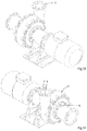
Fig. 1 is a perspective view of a part of an embodiment of the slurry pump according to the invention, showing the pump without a protective cover. -
Fig. 2 is a similar view asFig. 1 , but showing the opposite side of the slurry pump. -
Figs. 3-7 are a top view and four side views, respectively, of the embodiment ofFig. 1 on a smaller scale. -
Figs. 8-12 are similar views asFigs. 3-7 , but showing the slurry pump including the protective cover according to the invention. -
Figs. 13 and 14 are similar views asFigs. 1 and 2 , but showing the slurry pump without holding members for holding the protective cover. -
Figs. 15 and 16 are similar views asFigs. 13 and 14 , but showing the slurry pump including parts of the holding members for holding the protective cover. -
Figs. 17 and 18 are perspective views of wedge-shaped blocks for fixing the protective cover. -
Fig. 19 is a perspective view of a part of a counter outlet flange for fixing the protective cover. -
Fig. 20 is a sectional view of the holding member at the suction inlet. -
Fig. 21 is a sectional view of the holding member at the outlet. -
Fig. 22 is a perspective view of an alternative embodiment of the slurry pump according to the invention, showing the pump without a protective cover. -
Fig. 23 is a frontal view of a part of the embodiment ofFig. 22 on a larger scale. -
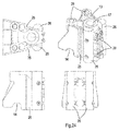
Fig. 24 is a top view, a perspective view, a side view and a front view of a holding member of the embodiment ofFig. 22 on a larger scale. -
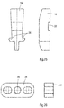
Fig. 25 is a top view and a side view of a crease flattener of the embodiment ofFig. 22 on a larger scale. -
Fig. 26 is a top view and a side view of a fitting plate of the embodiment ofFig. 22 on a larger scale. -
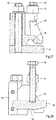
Figs. 27 and 28 are cross-sectional views at a holding member and a crease flattener, respectively, of the embodiment ofFig. 22 on a larger scale. -
Fig. 29 is a top view, a side view and a perspective view of a pressure element of the embodiment ofFig. 22 on a larger scale. -
Figs. 1-7 show different views of aslurry pump 1 without a protective cover, andFigs. 8-11 show different views of an embodiment of theslurry pump 1 including aprotective cover 2 according to the invention. In particularFigs. 3-7 andFigs. 8-12 are views from the same respective sides, showing the embodiment of theslurry pump 1 without and with theprotective cover 2, respectively. Theslurry pump 1 including thecover 2 can be installed on board of a dredging vessel (not shown). Such a dredging vessel is provided with a suction tube and a cutting mechanism located nearby an inlet of the suction tube. The cutting mechanism loosens the bed material of a sea bed, a river bed or a lake bed, for example, and a mixture of solids and water is then sucked up by theslurry pump 1 via the suction tube. Theslurry pump 1 according to the invention is not limited to dredging applications, but is also suitable for pumping liquid and solid particle mixtures in other fields, for example in the mining industry. - The
slurry pump 1 as shown in the figures is a centrifugal pump and has acasing 3 which accommodates an impeller (not shown). The impeller has an impeller shaft which is supported by bearings, located in a bearing housing. The impeller shaft is driven by anelectric motor 4. Alternatively, the impeller shaft may be driven by alternative driving means such as an internal combustion engine, hydraulic motor or the like, possibly via a transmission. Thecasing 3 has asuction inlet 5 and a tangentially orientedoutlet 6. Thecasing 3 comprises a volute or cup shapedpart 3a and a substantiallyflat impeller lid 3b which is bolted to the cup shapedpart 3a at the side of thepump 1 where thesuction inlet 5 is located. Theimpeller lid 3b is removable in order to easily reach the impeller in case of maintenance or replacement of a worn impeller. At a side of thecasing 3 opposite to the side where theimpeller lid 3b is located, the impeller shaft leaves thecasing 3. - In practice, the slurry or dredged material may also contain unexploded ordnance like grenades and bombs which may detonate upon entering the
slurry pump 1 such that thecasing 3 will be damaged and fragments of thecasing 3 will be ejected. In order to avoid a dangerous situation for operators and equipment thecasing 3 is enveloped by theprotective cover 2. Thecover 2 in the embodiment as shown inFigs. 8-12 comprises a flexible fabric which is wrapped around thecasing 3. Thecover 2 is made of a woven fabric and comprises plastic fibres, for example para-aramid synthetic fibre known under the registered trademarks Kevlar or Twaron or polyethylene fibre under the registered trademarks Dyneema or Spectra. Such fibres are also used for manufacturing bulletproof vests, for example. Nevertheless, alternative fibres are possible. - The protective cover as shown in
Figs. 8-12 forms a bag which surrounds thecasing 3 and which comprises three holes at thesuction inlet 5, theoutlet 6 and the side of thecasing 3 where theelectric motor 4 is located. At these locations theprotective cover 2 is attached to thecasing 3. In the embodiment as shown in the figures thecasing 3 is provided with anoutlet flange 7 at theoutlet 6, seeFig. 14 . Theprotective cover 2 is clamped to theoutlet flange 7 by acounter outlet flange 8, as illustrated inFigs. 8-12 . Thecounter outlet flange 8 comprises three portions which are bolted to each other. One of the three portions is shown inFig. 19 .Fig. 21 shows in cross-section how theprotective cover 2 is clamped between theoutlet flange 7 and thecounter outlet flange 8. It is noted that there are numerous alternative means for fixing theprotective cover 2 to theoutlet 6. - At the
suction inlet 5 and the opposite side of thecasing 3 facing theelectric motor 4, theprotective cover 2 is fixed in more or less the same manner.Figs. 15 and 16 show that aninlet flange 9 is mounted at thesuction inlet 5 and animpeller shaft flange 10 is mounted at the side of thecasing 3 facing theelectric motor 4. For clarity reasons, it is referred toFigs. 13 and 14 which are similar views asFigs. 15 and 16 , but in which theinlet flange 9 and theimpeller shaft flange 10 are not shown. Theinlet flange 9 is mounted to thecasing 3 by means of welding whereas theimpeller shaft flange 10 is bolted to thecasing 3. - The
protective cover 2 can be fixed at theinlet flange 9 and at theimpeller shaft flange 10 by means of wedge-shapedblocks 13 which are bolted to therespective flanges blocks 13 is provided with acavity 14, seeFigs. 17 and 18 . After installing allblocks 13 thecavities 14 form a ring-shaped channel between theblocks 13 and therespective flanges -
Fig. 20 shows how theprotective cover 2 is fixed at theinlet flange 9. Theprotective cover 2 is fixed to theimpeller shaft flange 10 in the same way. It can be seen inFig. 20 that theprotective cover 2 at its end edge is provided with ahem 11 with astring 12 therein which is accommodated in themating cavity 14 of the wedge-shapedblocks 13. Thestring 12 and a portion of thehem 11 are clamped between theblocks 13 and therespective flanges -
Figs. 11 and 12 illustrate that creases 15 in theprotective cover 2 are present at theinlet flange 9 and theimpeller shaft flange 10. Thecreases 15 arise since the surface for fixing theprotective cover 2 at theinlet flange 9 is smaller than the surface of theprotective cover 2 at that location. Thecreases 15 may protrude outwardly and clamped between respective neighbouring wedge-shapedblocks 13. - In case of maintenance or replacement of a worn impeller the
blocks 13 at theinlet flange 9 can be loosened and theprotective cover 2 can be folded backwards in order to provide access to the bolts of theimpeller lid 3b so as to be able to remove thelid 3b. -
Fig. 22 shows analternative slurry pump 1 andFig. 23 shows a part of thepump 1 at thesuction inlet 5. For explanatory reasons thepump 1 is depicted without theprotective cover 2. This embodiment has different holding members or blocks 13 than the embodiment as described above. In this embodiment thesuction inlet 5 is provided with twelveblocks 13.Fig. 24 shows different views of one of theblocks 13. Theblock 13 has also a wedge-shape as seen from above and comprises acavity 14, as well. After installing allblocks 13 on the cooperatinginlet flange 9 thecavities 14 form a ring-shaped channel between theblocks 13 and theinlet flange 9 for receiving thestring 12 enveloped by theprotective cover 2. Each of theblocks 13 is mounted to theinlet flange 9 via a threadedpin 16 running through a through-hole 17 in theblock 13 and fixed thereto by a nut, in a similar way as theblocks 13 in the previous embodiment. - After clamping the
protective cover 2 including thestring 12 between theblocks 13 and theinlet flange 9, creases 15 of theprotective cover 2 are present between neighbouring blocks 13. Thecreases 15 are flattened by means ofcrease flatteners 18 such that theprotective cover 2 forms a watertight sealing.Figs. 22 and23 show that thecrease flatteners 18 are located between each two neighbouringblocks 13. As shown inFig. 25 thecrease flattener 18 has a wedge shape and fits between two neighbouringblocks 13 which can be observed inFig. 23 . Each of thecrease flatteners 18 is pressed onto acrease 15 by means of acrease flattener bolt 19 which is screwed in a tappedhole 20 of afitting plate 21, seeFig. 26 , and ends in arecess 22 of thecrease flattener 18. Thefitting plate 21 is mounted on two neighbouringblocks 13 by means offitting plate bolts 23, seeFigs. 22 and23 . Thefitting plate bolts 23 are screwed in mating holes 29 in theblocks 12. - In order to avoid a bending force on the
crease flattener bolt 19 in case of a pulling force on theprotective cover 2, thecrease flattener 18 is provided withlateral protrusions 24 which fit in mating recesses 25 of theadjacent blocks 13 such that thecrease flatteners 18 are locked with respect to theblocks 13 in radial outward direction of theinlet flange 9. -
Figs. 27 and 28 illustrate an assembled situation by cross-sectional views taken along a plane through theblock 13 at the threadedpin 16 and the through-hole 17 and taken along a plane through thecrease flattener 18, respectively. -
Fig. 29 shows different views of apressure element 26, which has a semi-circular cross-section. Eachblock 13 is provided with twopressure elements 26 of which the curved portions face away from each other. In assembled condition acrease 15 between twoadjacent blocks 13 is flattened and clamped to theinlet flange 9 by thecrease flattener 18, whereas thepressure elements 26 of two neighbouringblocks 13 prevent theprotective cover 2 from moving out of the space between theblocks 13, theinlet flange 9 and thecrease flattener 18 upon exerting a pulling force on theprotective cover 2. This is caused by the fact that the amount of material of theprotective cover 2 in radial inward direction of theinlet flange 9 beyond thepressure elements 26 increases which increases resistance during displacement of theprotective cover 2 in outward direction. Besides, thepressure elements 26 are freely movable in radial outward direction of theinlet flange 9, sinceprotrusions 27 at the back side of thepressure elements 26 slidably fit in cooperatingrails 28 of theblocks 13. Therails 28 of ablock 13 are diverging in radial outward direction of theinlet flange 9. This means that upon a sudden pulling force on theprotective cover 2, thecover 2 may pull thepressure elements 26 in radial outward direction such that the distance between neighbouringpressure elements 26 decreases. Consequently, it becomes still more difficult to move thecrease 15 of thecover 2 in radial outward direction of theinlet flange 9. -
Figs. 22-29 show the manner of fixing theprotective cover 2 at thesuction inlet 5, but a similar manner can be used for fixing theprotective cover 2 at theimpeller shaft flange 10. - The invention is not limited to the embodiments as shown in the drawings and described hereinbefore, which may be varied in different manners within the scope of the claims. For example, alternative holding members are conceivable for fixing the protective cover to the casing.
Claims (14)
- A slurry pump (1) for pumping a liquid and solid particle mixture, comprising a casing (3) which accommodates a drivable impeller and includes a suction inlet (5) and an outlet (6), and protection means (2) for protecting the environment against leakage of liquid or ejection of fragments of the casing (3) in case of damage thereof, characterized in that the protection means comprises a protective cover (2) which is wrapped around the casing (3).
- A slurry pump (1) according to claim 1, wherein the cover (2) comprises a flexible fabric.
- A slurry pump (1) according to claim 1 or 2, wherein the cover (2) comprises a textile.
- A slurry pump (1) according to one of the preceding claims, wherein the cover (2) comprises a woven fabric or non-woven material.
- A slurry pump (1) according to claim 4, wherein the fabric comprises plastic fibres.
- A slurry pump (1) according to one of the preceding claims, wherein the impeller is coupled to an impeller drive shaft which leaves the casing (3) at a drive shaft side (10) as seen from the impeller, wherein the protective cover (2) is attached to the casing (3) through holding members (7, 8, 9, 10, 13) at the suction inlet (5), at the outlet (6) and the drive shaft side (10).
- A slurry pump (1) according to claim 6, wherein at least one of the holding members comprises a flange (7, 9, 10) and a clamp (8, 13) for clamping the protective cover (2) between the clamp (8, 13) and the flange (7, 9, 10).
- A slurry pump (1) according to claim 7, wherein the clamp is formed of a plurality of blocks (13) which are mountable to the flange (9, 10) in circumferential direction thereof.
- A slurry pump (1) according to claim 8, wherein each of the blocks (13) is provided with a cavity (14) at its side facing the flange (9, 10) which is arranged such that after mounting the blocks (13) on the flange (9, 10) the cavities (14) form a ring-shaped channel between the blocks (13) and the flange (9, 10) for receiving a thickened end portion of the cover (2) for receiving a thickened end portion of the cover (2).
- A slurry pump (1) according to claim 9, wherein the protective cover (2) at the flange (9, 10) is folded about a string (12) hence forming a hem (11) with the string (12) therein, wherein at least a part of the hem (11) including the string (12) is accommodated in said ring-shaped channel.
- A slurry pump (1) according to one of the claims 8-10, wherein a crease flattener (18) is fixed between two neighbouring blocks (13), which crease flattener (18) presses a crease (15) of the protective cover (2) against the flange (9, 10).
- A slurry pump (1) according to claim 11, wherein the crease flattener (18) and the blocks (13) are provided with cooperating locking members (24, 25) for locking the crease flattener (18) between the blocks (13) in a radial direction of the flange (9, 10).
- A slurry pump (1) according to one of the claims 8-12, wherein each of the blocks (13) are provided with at least two pressure elements (26), which are freely movable with respect to the flange (9, 10) in radial outward direction thereof, wherein the pressure elements (26) of two neighbouring blocks (13) face each other and a crease (15) of the protective cover (2) extends between the pressure elements (26), wherein the pressure elements (26) in circumferential direction of the flange (9, 10) and the blocks (13) are adapted such that the distance between the pressure elements (26) decreases upon moving the pressure elements (26) in radial outward direction thereof.
- A slurry pump (1) according to claims 11 and 13, wherein the pressure elements (26) are movable outside the crease flattener (18).
Priority Applications (1)
| Application Number | Priority Date | Filing Date | Title |
|---|---|---|---|
| EP16162861.5A EP3225843B1 (en) | 2016-03-30 | 2016-03-30 | A slurry pump |
Applications Claiming Priority (1)
| Application Number | Priority Date | Filing Date | Title |
|---|---|---|---|
| EP16162861.5A EP3225843B1 (en) | 2016-03-30 | 2016-03-30 | A slurry pump |
Publications (2)
| Publication Number | Publication Date |
|---|---|
| EP3225843A1 true EP3225843A1 (en) | 2017-10-04 |
| EP3225843B1 EP3225843B1 (en) | 2019-05-08 |
Family
ID=55650252
Family Applications (1)
| Application Number | Title | Priority Date | Filing Date |
|---|---|---|---|
| EP16162861.5A Active EP3225843B1 (en) | 2016-03-30 | 2016-03-30 | A slurry pump |
Country Status (1)
| Country | Link |
|---|---|
| EP (1) | EP3225843B1 (en) |
Cited By (3)
| Publication number | Priority date | Publication date | Assignee | Title |
|---|---|---|---|---|
| CN108180170A (en) * | 2018-01-30 | 2018-06-19 | 河南省西峡汽车水泵股份有限公司 | A kind of method for installing cover board |
| CN111608918A (en) * | 2020-05-28 | 2020-09-01 | 陕西省环境保护公司 | Anti-clogging device of sludge pump in methanol sewage treatment |
| CN117212181A (en) * | 2023-10-13 | 2023-12-12 | 河北技投机械设备有限公司 | Long life slurry pump for easy installation |
Citations (7)
| Publication number | Priority date | Publication date | Assignee | Title |
|---|---|---|---|---|
| US5437538A (en) * | 1990-06-18 | 1995-08-01 | General Electric Company | Projectile shield |
| JP2002096413A (en) * | 2000-09-21 | 2002-04-02 | Toray Ind Inc | Composite reinforced fiber substrate and preform |
| EP1584797A2 (en) * | 2004-04-08 | 2005-10-12 | General Electric Company | A containment apparatus for a gas turbine engine |
| CN101149066A (en) * | 2007-09-07 | 2008-03-26 | 济南东方天明机械有限公司 | Centrifugal type slurry pump impeller adjusting gap scouring and erosion-reducing technology and apparatus |
| EP1906029A1 (en) * | 2006-09-19 | 2008-04-02 | IHC Holland IE B.V. | Centrifugal pump having an inner casing and an outer casing |
| EP1972788A1 (en) * | 2007-03-23 | 2008-09-24 | IHC Holland IE B.V. | Centrifugal pump housing having a flat single cover part |
| JP2013092049A (en) * | 2011-10-24 | 2013-05-16 | Ube Techno Enji Kk | Slurry pump |
-
2016
- 2016-03-30 EP EP16162861.5A patent/EP3225843B1/en active Active
Patent Citations (7)
| Publication number | Priority date | Publication date | Assignee | Title |
|---|---|---|---|---|
| US5437538A (en) * | 1990-06-18 | 1995-08-01 | General Electric Company | Projectile shield |
| JP2002096413A (en) * | 2000-09-21 | 2002-04-02 | Toray Ind Inc | Composite reinforced fiber substrate and preform |
| EP1584797A2 (en) * | 2004-04-08 | 2005-10-12 | General Electric Company | A containment apparatus for a gas turbine engine |
| EP1906029A1 (en) * | 2006-09-19 | 2008-04-02 | IHC Holland IE B.V. | Centrifugal pump having an inner casing and an outer casing |
| EP1972788A1 (en) * | 2007-03-23 | 2008-09-24 | IHC Holland IE B.V. | Centrifugal pump housing having a flat single cover part |
| CN101149066A (en) * | 2007-09-07 | 2008-03-26 | 济南东方天明机械有限公司 | Centrifugal type slurry pump impeller adjusting gap scouring and erosion-reducing technology and apparatus |
| JP2013092049A (en) * | 2011-10-24 | 2013-05-16 | Ube Techno Enji Kk | Slurry pump |
Cited By (3)
| Publication number | Priority date | Publication date | Assignee | Title |
|---|---|---|---|---|
| CN108180170A (en) * | 2018-01-30 | 2018-06-19 | 河南省西峡汽车水泵股份有限公司 | A kind of method for installing cover board |
| CN111608918A (en) * | 2020-05-28 | 2020-09-01 | 陕西省环境保护公司 | Anti-clogging device of sludge pump in methanol sewage treatment |
| CN117212181A (en) * | 2023-10-13 | 2023-12-12 | 河北技投机械设备有限公司 | Long life slurry pump for easy installation |
Also Published As
| Publication number | Publication date |
|---|---|
| EP3225843B1 (en) | 2019-05-08 |
Similar Documents
| Publication | Publication Date | Title |
|---|---|---|
| EP3225843B1 (en) | A slurry pump | |
| US4305214A (en) | In-line centrifugal pump | |
| US4904159A (en) | Pump impeller | |
| RU2654923C2 (en) | Apparatus and method for dredging of sediments from seabed | |
| US4974998A (en) | Wear-resistant centrifugal solids pump lining | |
| CN107934413B (en) | Underwater coarse-particle mineral screw feeder | |
| FI125993B (en) | Milling unit with pump | |
| US7854402B1 (en) | Hydraulic system valving | |
| US8590297B2 (en) | Hydraulically-powered compressor | |
| EP1972788B1 (en) | Centrifugal pump housing having a flat single cover part | |
| KR101012750B1 (en) | Dredging device | |
| US4913631A (en) | Turbine-driven rotary pump | |
| EP1892419A2 (en) | Two stage conical liquid ring pump having removable manifold, shims and first and second stage head o'ring receiving boss | |
| US5316449A (en) | Motor-driven pump with reaction turbine | |
| US1107591A (en) | Pump construction. | |
| EP1855012A1 (en) | Centrifugal pump having an inner casing and an outer casing | |
| EP1906029A1 (en) | Centrifugal pump having an inner casing and an outer casing | |
| US5267830A (en) | Pump for abrasive materials | |
| US427060A (en) | Centrifugal pump | |
| US20240351046A1 (en) | Screening bucket | |
| CN218300890U (en) | Sealed sand pumping box for pumping sand | |
| US4780972A (en) | Wheelmotor drive for rotary cutterhead | |
| CN106769018B (en) | Test box of hydraulic coupler | |
| CN114294239B (en) | Shield slurry conveying pump | |
| CN102954001A (en) | Improved centrifugal pump |
Legal Events
| Date | Code | Title | Description |
|---|---|---|---|
| PUAI | Public reference made under article 153(3) epc to a published international application that has entered the european phase |
Free format text: ORIGINAL CODE: 0009012 |
|
| STAA | Information on the status of an ep patent application or granted ep patent |
Free format text: STATUS: THE APPLICATION HAS BEEN PUBLISHED |
|
| AK | Designated contracting states |
Kind code of ref document: A1 Designated state(s): AL AT BE BG CH CY CZ DE DK EE ES FI FR GB GR HR HU IE IS IT LI LT LU LV MC MK MT NL NO PL PT RO RS SE SI SK SM TR |
|
| AX | Request for extension of the european patent |
Extension state: BA ME |
|
| STAA | Information on the status of an ep patent application or granted ep patent |
Free format text: STATUS: REQUEST FOR EXAMINATION WAS MADE |
|
| 17P | Request for examination filed |
Effective date: 20180328 |
|
| RBV | Designated contracting states (corrected) |
Designated state(s): AL AT BE BG CH CY CZ DE DK EE ES FI FR GB GR HR HU IE IS IT LI LT LU LV MC MK MT NL NO PL PT RO RS SE SI SK SM TR |
|
| STAA | Information on the status of an ep patent application or granted ep patent |
Free format text: STATUS: EXAMINATION IS IN PROGRESS |
|
| 17Q | First examination report despatched |
Effective date: 20180821 |
|
| GRAP | Despatch of communication of intention to grant a patent |
Free format text: ORIGINAL CODE: EPIDOSNIGR1 |
|
| STAA | Information on the status of an ep patent application or granted ep patent |
Free format text: STATUS: GRANT OF PATENT IS INTENDED |
|
| INTG | Intention to grant announced |
Effective date: 20181116 |
|
| GRAS | Grant fee paid |
Free format text: ORIGINAL CODE: EPIDOSNIGR3 |
|
| GRAA | (expected) grant |
Free format text: ORIGINAL CODE: 0009210 |
|
| STAA | Information on the status of an ep patent application or granted ep patent |
Free format text: STATUS: THE PATENT HAS BEEN GRANTED |
|
| AK | Designated contracting states |
Kind code of ref document: B1 Designated state(s): AL AT BE BG CH CY CZ DE DK EE ES FI FR GB GR HR HU IE IS IT LI LT LU LV MC MK MT NL NO PL PT RO RS SE SI SK SM TR |
|
| REG | Reference to a national code |
Ref country code: GB Ref legal event code: FG4D |
|
| REG | Reference to a national code |
Ref country code: CH Ref legal event code: EP Ref country code: AT Ref legal event code: REF Ref document number: 1130530 Country of ref document: AT Kind code of ref document: T Effective date: 20190515 |
|
| REG | Reference to a national code |
Ref country code: IE Ref legal event code: FG4D |
|
| REG | Reference to a national code |
Ref country code: DE Ref legal event code: R096 Ref document number: 602016013468 Country of ref document: DE |
|
| REG | Reference to a national code |
Ref country code: NL Ref legal event code: FP |
|
| REG | Reference to a national code |
Ref country code: LT Ref legal event code: MG4D |
|
| PG25 | Lapsed in a contracting state [announced via postgrant information from national office to epo] |
Ref country code: HR Free format text: LAPSE BECAUSE OF FAILURE TO SUBMIT A TRANSLATION OF THE DESCRIPTION OR TO PAY THE FEE WITHIN THE PRESCRIBED TIME-LIMIT Effective date: 20190508 Ref country code: LT Free format text: LAPSE BECAUSE OF FAILURE TO SUBMIT A TRANSLATION OF THE DESCRIPTION OR TO PAY THE FEE WITHIN THE PRESCRIBED TIME-LIMIT Effective date: 20190508 Ref country code: SE Free format text: LAPSE BECAUSE OF FAILURE TO SUBMIT A TRANSLATION OF THE DESCRIPTION OR TO PAY THE FEE WITHIN THE PRESCRIBED TIME-LIMIT Effective date: 20190508 Ref country code: NO Free format text: LAPSE BECAUSE OF FAILURE TO SUBMIT A TRANSLATION OF THE DESCRIPTION OR TO PAY THE FEE WITHIN THE PRESCRIBED TIME-LIMIT Effective date: 20190808 Ref country code: PT Free format text: LAPSE BECAUSE OF FAILURE TO SUBMIT A TRANSLATION OF THE DESCRIPTION OR TO PAY THE FEE WITHIN THE PRESCRIBED TIME-LIMIT Effective date: 20190908 Ref country code: AL Free format text: LAPSE BECAUSE OF FAILURE TO SUBMIT A TRANSLATION OF THE DESCRIPTION OR TO PAY THE FEE WITHIN THE PRESCRIBED TIME-LIMIT Effective date: 20190508 Ref country code: FI Free format text: LAPSE BECAUSE OF FAILURE TO SUBMIT A TRANSLATION OF THE DESCRIPTION OR TO PAY THE FEE WITHIN THE PRESCRIBED TIME-LIMIT Effective date: 20190508 |
|
| PG25 | Lapsed in a contracting state [announced via postgrant information from national office to epo] |
Ref country code: BG Free format text: LAPSE BECAUSE OF FAILURE TO SUBMIT A TRANSLATION OF THE DESCRIPTION OR TO PAY THE FEE WITHIN THE PRESCRIBED TIME-LIMIT Effective date: 20190808 Ref country code: GR Free format text: LAPSE BECAUSE OF FAILURE TO SUBMIT A TRANSLATION OF THE DESCRIPTION OR TO PAY THE FEE WITHIN THE PRESCRIBED TIME-LIMIT Effective date: 20190809 Ref country code: RS Free format text: LAPSE BECAUSE OF FAILURE TO SUBMIT A TRANSLATION OF THE DESCRIPTION OR TO PAY THE FEE WITHIN THE PRESCRIBED TIME-LIMIT Effective date: 20190508 Ref country code: LV Free format text: LAPSE BECAUSE OF FAILURE TO SUBMIT A TRANSLATION OF THE DESCRIPTION OR TO PAY THE FEE WITHIN THE PRESCRIBED TIME-LIMIT Effective date: 20190508 |
|
| REG | Reference to a national code |
Ref country code: AT Ref legal event code: MK05 Ref document number: 1130530 Country of ref document: AT Kind code of ref document: T Effective date: 20190508 |
|
| PG25 | Lapsed in a contracting state [announced via postgrant information from national office to epo] |
Ref country code: EE Free format text: LAPSE BECAUSE OF FAILURE TO SUBMIT A TRANSLATION OF THE DESCRIPTION OR TO PAY THE FEE WITHIN THE PRESCRIBED TIME-LIMIT Effective date: 20190508 Ref country code: DK Free format text: LAPSE BECAUSE OF FAILURE TO SUBMIT A TRANSLATION OF THE DESCRIPTION OR TO PAY THE FEE WITHIN THE PRESCRIBED TIME-LIMIT Effective date: 20190508 Ref country code: SK Free format text: LAPSE BECAUSE OF FAILURE TO SUBMIT A TRANSLATION OF THE DESCRIPTION OR TO PAY THE FEE WITHIN THE PRESCRIBED TIME-LIMIT Effective date: 20190508 Ref country code: RO Free format text: LAPSE BECAUSE OF FAILURE TO SUBMIT A TRANSLATION OF THE DESCRIPTION OR TO PAY THE FEE WITHIN THE PRESCRIBED TIME-LIMIT Effective date: 20190508 Ref country code: AT Free format text: LAPSE BECAUSE OF FAILURE TO SUBMIT A TRANSLATION OF THE DESCRIPTION OR TO PAY THE FEE WITHIN THE PRESCRIBED TIME-LIMIT Effective date: 20190508 Ref country code: CZ Free format text: LAPSE BECAUSE OF FAILURE TO SUBMIT A TRANSLATION OF THE DESCRIPTION OR TO PAY THE FEE WITHIN THE PRESCRIBED TIME-LIMIT Effective date: 20190508 |
|
| REG | Reference to a national code |
Ref country code: DE Ref legal event code: R097 Ref document number: 602016013468 Country of ref document: DE |
|
| PG25 | Lapsed in a contracting state [announced via postgrant information from national office to epo] |
Ref country code: IT Free format text: LAPSE BECAUSE OF FAILURE TO SUBMIT A TRANSLATION OF THE DESCRIPTION OR TO PAY THE FEE WITHIN THE PRESCRIBED TIME-LIMIT Effective date: 20190508 Ref country code: SM Free format text: LAPSE BECAUSE OF FAILURE TO SUBMIT A TRANSLATION OF THE DESCRIPTION OR TO PAY THE FEE WITHIN THE PRESCRIBED TIME-LIMIT Effective date: 20190508 |
|
| PLBE | No opposition filed within time limit |
Free format text: ORIGINAL CODE: 0009261 |
|
| STAA | Information on the status of an ep patent application or granted ep patent |
Free format text: STATUS: NO OPPOSITION FILED WITHIN TIME LIMIT |
|
| PG25 | Lapsed in a contracting state [announced via postgrant information from national office to epo] |
Ref country code: TR Free format text: LAPSE BECAUSE OF FAILURE TO SUBMIT A TRANSLATION OF THE DESCRIPTION OR TO PAY THE FEE WITHIN THE PRESCRIBED TIME-LIMIT Effective date: 20190508 |
|
| 26N | No opposition filed |
Effective date: 20200211 |
|
| PG25 | Lapsed in a contracting state [announced via postgrant information from national office to epo] |
Ref country code: PL Free format text: LAPSE BECAUSE OF FAILURE TO SUBMIT A TRANSLATION OF THE DESCRIPTION OR TO PAY THE FEE WITHIN THE PRESCRIBED TIME-LIMIT Effective date: 20190508 |
|
| PG25 | Lapsed in a contracting state [announced via postgrant information from national office to epo] |
Ref country code: SI Free format text: LAPSE BECAUSE OF FAILURE TO SUBMIT A TRANSLATION OF THE DESCRIPTION OR TO PAY THE FEE WITHIN THE PRESCRIBED TIME-LIMIT Effective date: 20190508 |
|
| PG25 | Lapsed in a contracting state [announced via postgrant information from national office to epo] |
Ref country code: MC Free format text: LAPSE BECAUSE OF FAILURE TO SUBMIT A TRANSLATION OF THE DESCRIPTION OR TO PAY THE FEE WITHIN THE PRESCRIBED TIME-LIMIT Effective date: 20190508 Ref country code: ES Free format text: LAPSE BECAUSE OF FAILURE TO SUBMIT A TRANSLATION OF THE DESCRIPTION OR TO PAY THE FEE WITHIN THE PRESCRIBED TIME-LIMIT Effective date: 20190508 |
|
| REG | Reference to a national code |
Ref country code: CH Ref legal event code: PL |
|
| REG | Reference to a national code |
Ref country code: NL Ref legal event code: RC Free format text: DETAILS LICENCE OR PLEDGE: RIGHT OF PLEDGE, ESTABLISHED Name of requester: ABN AMRO BANK N.V. Effective date: 20201012 |
|
| PG25 | Lapsed in a contracting state [announced via postgrant information from national office to epo] |
Ref country code: LU Free format text: LAPSE BECAUSE OF NON-PAYMENT OF DUE FEES Effective date: 20200330 |
|
| PG25 | Lapsed in a contracting state [announced via postgrant information from national office to epo] |
Ref country code: LI Free format text: LAPSE BECAUSE OF NON-PAYMENT OF DUE FEES Effective date: 20200331 Ref country code: CH Free format text: LAPSE BECAUSE OF NON-PAYMENT OF DUE FEES Effective date: 20200331 Ref country code: FR Free format text: LAPSE BECAUSE OF NON-PAYMENT OF DUE FEES Effective date: 20200331 Ref country code: IE Free format text: LAPSE BECAUSE OF NON-PAYMENT OF DUE FEES Effective date: 20200330 |
|
| GBPC | Gb: european patent ceased through non-payment of renewal fee |
Effective date: 20200330 |
|
| REG | Reference to a national code |
Ref country code: BE Ref legal event code: RC Free format text: DETAILS PLEDGE: RIGHT OF PLEDGE, ESTABLISHED Name of requester: ABN AMRO BANK N.V. Effective date: 20210204 |
|
| PG25 | Lapsed in a contracting state [announced via postgrant information from national office to epo] |
Ref country code: GB Free format text: LAPSE BECAUSE OF NON-PAYMENT OF DUE FEES Effective date: 20200330 |
|
| PG25 | Lapsed in a contracting state [announced via postgrant information from national office to epo] |
Ref country code: MT Free format text: LAPSE BECAUSE OF FAILURE TO SUBMIT A TRANSLATION OF THE DESCRIPTION OR TO PAY THE FEE WITHIN THE PRESCRIBED TIME-LIMIT Effective date: 20190508 Ref country code: CY Free format text: LAPSE BECAUSE OF FAILURE TO SUBMIT A TRANSLATION OF THE DESCRIPTION OR TO PAY THE FEE WITHIN THE PRESCRIBED TIME-LIMIT Effective date: 20190508 |
|
| PG25 | Lapsed in a contracting state [announced via postgrant information from national office to epo] |
Ref country code: MK Free format text: LAPSE BECAUSE OF FAILURE TO SUBMIT A TRANSLATION OF THE DESCRIPTION OR TO PAY THE FEE WITHIN THE PRESCRIBED TIME-LIMIT Effective date: 20190508 Ref country code: IS Free format text: LAPSE BECAUSE OF FAILURE TO SUBMIT A TRANSLATION OF THE DESCRIPTION OR TO PAY THE FEE WITHIN THE PRESCRIBED TIME-LIMIT Effective date: 20190908 |
|
| P01 | Opt-out of the competence of the unified patent court (upc) registered |
Effective date: 20230517 |
|
| REG | Reference to a national code |
Ref country code: NL Ref legal event code: RF Free format text: RIGHT OF PLEDGE, REMOVED Effective date: 20241231 Ref country code: NL Ref legal event code: RC Free format text: DETAILS LICENCE OR PLEDGE: RIGHT OF PLEDGE, ESTABLISHED Name of requester: ABN AMRO BANK N.V. Effective date: 20241231 |
|
| REG | Reference to a national code |
Ref country code: BE Ref legal event code: RF Free format text: DETAILS PLEDGE: RIGHT OF PLEDGE, REMOVED Effective date: 20250205 Ref country code: BE Ref legal event code: RF Free format text: DETAILS PLEDGE: RIGHT OF PLEDGE, REMOVED Name of requester: ABN AMRO BANK N.V. Effective date: 20250812 |
|
| PGFP | Annual fee paid to national office [announced via postgrant information from national office to epo] |
Ref country code: DE Payment date: 20260327 Year of fee payment: 11 |
|
| PGFP | Annual fee paid to national office [announced via postgrant information from national office to epo] |
Ref country code: BE Payment date: 20260327 Year of fee payment: 11 |
|
| PGFP | Annual fee paid to national office [announced via postgrant information from national office to epo] |
Ref country code: NL Payment date: 20260326 Year of fee payment: 11 |