EP3225829A1 - Internal combustion engine - Google Patents
Internal combustion engine Download PDFInfo
- Publication number
- EP3225829A1 EP3225829A1 EP17163560.0A EP17163560A EP3225829A1 EP 3225829 A1 EP3225829 A1 EP 3225829A1 EP 17163560 A EP17163560 A EP 17163560A EP 3225829 A1 EP3225829 A1 EP 3225829A1
- Authority
- EP
- European Patent Office
- Prior art keywords
- fuel
- introducing
- internal combustion
- combustion engine
- fuel pump
- Prior art date
- Legal status (The legal status is an assumption and is not a legal conclusion. Google has not performed a legal analysis and makes no representation as to the accuracy of the status listed.)
- Granted
Links
Images


Classifications
-
- F—MECHANICAL ENGINEERING; LIGHTING; HEATING; WEAPONS; BLASTING
- F02—COMBUSTION ENGINES; HOT-GAS OR COMBUSTION-PRODUCT ENGINE PLANTS
- F02M—SUPPLYING COMBUSTION ENGINES IN GENERAL WITH COMBUSTIBLE MIXTURES OR CONSTITUENTS THEREOF
- F02M59/00—Pumps specially adapted for fuel-injection and not provided for in groups F02M39/00 -F02M57/00, e.g. rotary cylinder-block type of pumps
- F02M59/44—Details, components parts, or accessories not provided for in, or of interest apart from, the apparatus of groups F02M59/02 - F02M59/42; Pumps having transducers, e.g. to measure displacement of pump rack or piston
-
- F—MECHANICAL ENGINEERING; LIGHTING; HEATING; WEAPONS; BLASTING
- F02—COMBUSTION ENGINES; HOT-GAS OR COMBUSTION-PRODUCT ENGINE PLANTS
- F02M—SUPPLYING COMBUSTION ENGINES IN GENERAL WITH COMBUSTIBLE MIXTURES OR CONSTITUENTS THEREOF
- F02M37/00—Apparatus or systems for feeding liquid fuel from storage containers to carburettors or fuel-injection apparatus; Arrangements for purifying liquid fuel specially adapted for, or arranged on, internal-combustion engines
- F02M37/0047—Layout or arrangement of systems for feeding fuel
-
- F—MECHANICAL ENGINEERING; LIGHTING; HEATING; WEAPONS; BLASTING
- F02—COMBUSTION ENGINES; HOT-GAS OR COMBUSTION-PRODUCT ENGINE PLANTS
- F02B—INTERNAL-COMBUSTION PISTON ENGINES; COMBUSTION ENGINES IN GENERAL
- F02B77/00—Component parts, details or accessories, not otherwise provided for
- F02B77/11—Thermal or acoustic insulation
-
- F—MECHANICAL ENGINEERING; LIGHTING; HEATING; WEAPONS; BLASTING
- F02—COMBUSTION ENGINES; HOT-GAS OR COMBUSTION-PRODUCT ENGINE PLANTS
- F02F—CYLINDERS, PISTONS OR CASINGS, FOR COMBUSTION ENGINES; ARRANGEMENTS OF SEALINGS IN COMBUSTION ENGINES
- F02F1/00—Cylinders; Cylinder heads
- F02F1/24—Cylinder heads
-
- F—MECHANICAL ENGINEERING; LIGHTING; HEATING; WEAPONS; BLASTING
- F02—COMBUSTION ENGINES; HOT-GAS OR COMBUSTION-PRODUCT ENGINE PLANTS
- F02M—SUPPLYING COMBUSTION ENGINES IN GENERAL WITH COMBUSTIBLE MIXTURES OR CONSTITUENTS THEREOF
- F02M37/00—Apparatus or systems for feeding liquid fuel from storage containers to carburettors or fuel-injection apparatus; Arrangements for purifying liquid fuel specially adapted for, or arranged on, internal-combustion engines
- F02M37/04—Feeding by means of driven pumps
-
- F—MECHANICAL ENGINEERING; LIGHTING; HEATING; WEAPONS; BLASTING
- F02—COMBUSTION ENGINES; HOT-GAS OR COMBUSTION-PRODUCT ENGINE PLANTS
- F02M—SUPPLYING COMBUSTION ENGINES IN GENERAL WITH COMBUSTIBLE MIXTURES OR CONSTITUENTS THEREOF
- F02M39/00—Arrangements of fuel-injection apparatus with respect to engines; Pump drives adapted to such arrangements
- F02M39/02—Arrangements of fuel-injection apparatus to facilitate the driving of pumps; Arrangements of fuel-injection pumps; Pump drives
-
- F—MECHANICAL ENGINEERING; LIGHTING; HEATING; WEAPONS; BLASTING
- F02—COMBUSTION ENGINES; HOT-GAS OR COMBUSTION-PRODUCT ENGINE PLANTS
- F02M—SUPPLYING COMBUSTION ENGINES IN GENERAL WITH COMBUSTIBLE MIXTURES OR CONSTITUENTS THEREOF
- F02M53/00—Fuel-injection apparatus characterised by having heating, cooling or thermally-insulating means
-
- F—MECHANICAL ENGINEERING; LIGHTING; HEATING; WEAPONS; BLASTING
- F02—COMBUSTION ENGINES; HOT-GAS OR COMBUSTION-PRODUCT ENGINE PLANTS
- F02M—SUPPLYING COMBUSTION ENGINES IN GENERAL WITH COMBUSTIBLE MIXTURES OR CONSTITUENTS THEREOF
- F02M55/00—Fuel-injection apparatus characterised by their fuel conduits or their venting means; Arrangements of conduits between fuel tank and pump F02M37/00
- F02M55/004—Joints; Sealings
- F02M55/005—Joints; Sealings for high pressure conduits, e.g. connected to pump outlet or to injector inlet
-
- F—MECHANICAL ENGINEERING; LIGHTING; HEATING; WEAPONS; BLASTING
- F02—COMBUSTION ENGINES; HOT-GAS OR COMBUSTION-PRODUCT ENGINE PLANTS
- F02M—SUPPLYING COMBUSTION ENGINES IN GENERAL WITH COMBUSTIBLE MIXTURES OR CONSTITUENTS THEREOF
- F02M59/00—Pumps specially adapted for fuel-injection and not provided for in groups F02M39/00 -F02M57/00, e.g. rotary cylinder-block type of pumps
- F02M59/44—Details, components parts, or accessories not provided for in, or of interest apart from, the apparatus of groups F02M59/02 - F02M59/42; Pumps having transducers, e.g. to measure displacement of pump rack or piston
- F02M59/48—Assembling; Disassembling; Replacing
-
- F—MECHANICAL ENGINEERING; LIGHTING; HEATING; WEAPONS; BLASTING
- F02—COMBUSTION ENGINES; HOT-GAS OR COMBUSTION-PRODUCT ENGINE PLANTS
- F02M—SUPPLYING COMBUSTION ENGINES IN GENERAL WITH COMBUSTIBLE MIXTURES OR CONSTITUENTS THEREOF
- F02M2200/00—Details of fuel-injection apparatus, not otherwise provided for
- F02M2200/80—Fuel injection apparatus manufacture, repair or assembly
- F02M2200/803—Fuel injection apparatus manufacture, repair or assembly using clamp elements and fastening means; e.g. bolts or screws
-
- F—MECHANICAL ENGINEERING; LIGHTING; HEATING; WEAPONS; BLASTING
- F02—COMBUSTION ENGINES; HOT-GAS OR COMBUSTION-PRODUCT ENGINE PLANTS
- F02M—SUPPLYING COMBUSTION ENGINES IN GENERAL WITH COMBUSTIBLE MIXTURES OR CONSTITUENTS THEREOF
- F02M69/00—Low-pressure fuel-injection apparatus ; Apparatus with both continuous and intermittent injection; Apparatus injecting different types of fuel
- F02M69/04—Injectors peculiar thereto
- F02M69/042—Positioning of injectors with respect to engine, e.g. in the air intake conduit
- F02M69/046—Positioning of injectors with respect to engine, e.g. in the air intake conduit for injecting into both the combustion chamber and the intake conduit
Definitions
- the present invention relates to an internal combustion engine.
- the high pressure fuel pump is fixed, for example, to a cylinder head of the internal combustion engine, and is operated with rotation of a cam shaft of the internal combustion engine.
- Japanese Patent Publication No. 5730387 such a structure of a high pressure fuel pump, in which the fuel is pressurized as described above, that a part of the fuel which is fed from the fuel tank is allowed to pass through a housing of the high pressure fuel pump, without being pressurized to a high pressure, and can be fed to the intake passage fuel injection valve.
- Japanese Patent Publication No. 5730387 it is possible to cool the high pressure fuel pump with the fuel which is fed to the intake passage fuel injection valve, when the fuel is fed to the intake passage fuel injection valve only. Accordingly, when the internal combustion engine is operated by feeding the fuel to the intake passage fuel injection valve only, it is possible to restrain heat-up of the high pressure fuel pump due to the heat which is transmitted from the cylinder head of the internal combustion engine.
- the housing of the high pressure fuel pump must be provided with a fuel outlet and so on for feeding a low pressure fuel. Therefore, as compared with a high pressure fuel pump which is employed in such an internal combustion engine that the intake passage fuel injection valve is not provided and feeds the high pressure fuel only, it is necessary to impart a different structure to a body part of the housing or so, which will make common use of components difficult.
- An object of the invention is to provide an internal combustion engine which is provided with a cylinder inside fuel injection valve, an intake passage fuel injection valve, and a fuel pump for feeding a pressurized fuel to the cylinder inside fuel injection valve, enabling the fuel pump to be cooled with the fuel which is fed to the intake passage fuel injection valve, employing a simple structure.
- an internal combustion engine which includes: an intake passage fuel injection valve for injecting fuel into an intake passage; and a cylinder inside fuel injection valve for injecting fuel into a combustion chamber, the internal combustion engine comprising: a fuel pump which is configured to pressurize and feed fuel, which is fed from a fuel tank, to the cylinder inside fuel injection valve; a securing part which is provided on a cylinder head member of the internal combustion engine to secure the fuel pump; an introducing member having heat conductivity, the introducing member which is connected to the fuel pump, and which is formed with: a first introducing path for introducing fuel from the fuel tank to the fuel pump; and a second introducing path for introducing fuel from the fuel tank to the intake passage fuel injection valve; and a heat transmitting member which is configured to transmit heat between the introducing member and the securing part.
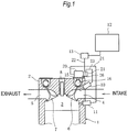
- Fig. 1 is a schematic structural view of an engine 1 (an internal combustion engine) in an embodiment according to the invention. It is to be noted that a single cylinder out of a multiple cylinder engine is shown in section, in Fig. 1 .
- the engine 1 in the embodiment according to the invention is, for example, an engine for driving an automobile.
- an intake port 4 an intake passage
- an exhaust port 5 communicating with a combustion chamber 3 are provided on a cylinder head 2 (a cylinder head member), and further, there are provided an intake valve 6 for opening or closing an opening between the intake port 4 and the combustion chamber 3, an exhaust valve 7 for opening or closing an opening between the exhaust port 5 and the combustion chamber 3, and an ignition plug 8 which is provided with an electrode on a face opposed to the combustion chamber 3.
- the cylinder head 2 of the engine 1 in this embodiment is provided with an intake passage fuel injection valve 10 for injecting fuel into the intake port 4, a cylinder inside fuel injection valve 11 for injecting the fuel into the combustion chamber 3, and a high pressure fuel pump 20 (a fuel pump) for pressurizing the fuel.
- the intake passage fuel injection valve 10 having its injection nozzle disposed in the intake port 4 injects a low pressure fuel which is fed from a fuel tank 12 by a feed pump 13, into the intake port 4. It is to be noted that this fuel injection by way of the intake passage fuel injection valve 10 is called as intake passage fuel injection (MPI).
- MPI intake passage fuel injection
- the cylinder inside fuel injection valve 11 having its injection nozzle disposed in the combustion engine 3, injects a high pressure fuel which is fed from the high pressure fuel pump 20, into the combustion chamber 3.
- the high pressure fuel pump 20 pressurizes the low pressure fuel which is fed from the fuel tank 12 via the feed pump 13, and feeds the pressurized fuel to the cylinder inside fuel injection valve 11. It is to be noted that this fuel injection by way of the cylinder inside fuel injection valve 11 is called as cylinder inside fuel injection (DI).
- the high pressure fuel pump 20 is fixed to a base 15 (a securing part) which is provided on an upper part or a side face of the cylinder head 2 with bolts or the like. Moreover, a feed pipe 21 (an introducing member) in a shape of a block is fixed to a side face of the high pressure fuel pump 20.
- a fuel feeding pipe 22 (a fuel feeding passage) to which the fuel is fed from the fuel tank 12 via the feed pump 13, and a low pressure fuel pipe 23 for feeding the fuel to the intake passage fuel injection valve 10 are connected to the feed pipe 21.
- a high pressure fuel pipe 24 which is connected to the cylinder inside fuel injection valve 11 is connected to the side face of the high pressure fuel pump 20.
- the fuel which is fed from the fuel feeding pipe 22 into the feed pipe 21 is fed to an inside of the high pressure fuel pump 20.
- the high pressure fuel pump 20 is operated by a cam which is provided on an intake cam shaft 16 for actuating the intake valve 6.
- the fuel which is fed via the fuel feeding pipe 22 and the feed pipe 21 is pressurized, and the pressurized fuel is fed to the cylinder inside fuel injection valve 11 via the high pressure fuel pipe 24.
- the fuel which is fed from the fuel feeding pipe 22 into the feed pipe 21 is branched inside the feed pipe 21, and fed to the intake passage fuel injection valve 10 via the low pressure fuel pipe 23, irrespective of the operation of the high pressure fuel pump 20.
- switching between an MPI mode and a DI mode is conducted by an engine control unit, which is not shown, for controlling the intake passage fuel injection valve 10 and the cylinder inside fuel injection valve 11.
- the DI mode is selected in a high load zone, while the MPI mode is selected in a low load zone.
- Fig. 2 is a plan view showing a mounting structure of the high pressure fuel pump 20 in this embodiment.
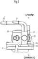
- Fig. 3 is a side elevation view showing the mounting structure of the high pressure fuel pump 20 in this embodiment.
- Fig. 4 is another side elevation view showing the mounting structure of the high pressure fuel pump 20 in this embodiment. It is to be noted that Fig. 3 is the side elevation view as seen in a direction of an arrow mark A in Fig. 2 , and Fig. 4 is the side elevation view as seen in a direction of an arrow mark B in Fig. 2 .
- the feed pipe 21 is fastened to the side face of the high pressure pump 20 with a piece of bolt 25.
- the fuel feeding pipe 22 and the low pressure fuel pipe 23 are connected to the feed pipe 21.
- the feed pipe 21 is formed of material having high heat conductivity such as aluminum.
- a lower face of the feed pipe 21 is positioned at an upper level than the base 15 which is positioned below the high pressure fuel pump 20.
- a gap 40 (a passage) is provided between an outer peripheral face of a shaft portion 30 of the bolt 25 and an inner peripheral face of the feed pipe 21.
- the shaft portion 30 of the bolt 25 is formed with a bolt inside communicating path 31 which is extended along a center line and opened at a distal end side.
- the bolt inside communicating path 31 has an opening on the outer peripheral face of the shaft portion 30 at a side opposed to the gap 40.
- a fuel feed communicating path 33 which interconnects the opening of the bolt inside communicating path 31 and the fuel feeding pipe 22
- a low pressure fuel feed communicating path 34 which interconnects the fuel feed communicating path 33 and the low pressure fuel pipe 23 via the gap 40.
- the fuel feed communicating path 33 and the bolt inside communicating path 31 cooperate to form a first introducing path 35 which introduces the fuel from the fuel feeding pipe 22 to the high pressure fuel pump 20.
- the fuel feed communicating path 33, the gap 40, and the low pressure fuel feed communicating path 34 cooperate to form a second introducing path 36.
- a part of the lower face of the feed pipe 21 is projected downward thereby to form a projected part 26 (a heat transmitting member) in a polyhedral shape.
- a lower face of the projected part 26 is in face contact with a face portion which is provided on the base 15.
- the high pressure fuel pump 20 is fixed to the base 15 which is provided on the cylinder head 2 of the engine 1, and therefore, the heat of the engine 1 is transmitted to the high pressure fuel pump 20 by way of the base 15.
- the engine 1 While the engine 1 is operated in the MPI mode only, out of the MPI mode and the DI mode, for example, on occasion of the operation of the engine 1 in the low load zone, the fuel stays inside the high pressure fuel pump 20. Therefore, when the engine 1 is operated in the MPI mode only, the heat of the engine 1 is transmitted to the high pressure fuel pump 20, and it is concerned that the fuel staying inside the high pressure fuel pump 20 may be heated.
- a part of the lower face of the feed pipe 21 is extended downward to form the projected part 26, and this projected part 26 is in contact with the base 15. Therefore, heat transmission occurs between the feed pipe 21 and the base 15 by way of the projected part 26. Accordingly, the base 15 can be cooled with the fuel which passes through the feed pipe 21, by way of the feed pipe 21 and the projected part 26. Because the base 15 is interposed between the cylinder head 2 of the engine 1 and the high pressure fuel pump 20, it is possible to effectively reduce the heat which is transmitted from the cylinder head 2 to the high pressure fuel pump 20, by cooling the base 15.
- the fuel feed communicating path 33 and the low pressure fuel feed communicating path 34 are communicated in the outer peripheral part of the shaft portion 30 of the bolt 25 inside the feed pipe 21, and there is provided the gap 40 for passing the fuel which is introduced form the first introducing path 35 to the second introducing path 36. Therefore, it is possible to effectively cool the feed pipe 21 with the fuel which passes through the gap 40. Particularly, it is possible to effectively cool the projected part 26 with the fuel which passes through the gap 40 at a position near the projected part 26.
- the feed pipe 21 is fixed to the side face of the high pressure fuel pump 20 by means of the single bolt 25, and therefore, the feed pipe 21 is fixed so as to rotate around an axis of the bolt 25 with respect to the high pressure fuel pump 20.
- the projected part 26 of the feed pipe 21 is in face contact with the base 15, this projected part 26 has a function of restricting the rotation of the feed pipe 21.
- the high pressure fuel pump 20 can be commonly used as the high pressure fuel pump to be used for the engine for the DI mode only. In this manner, reduction of the cost for the high pressure fuel pump 20 can be achieved.
- the present invention is not limited to the above described embodiment.
- the projected part 26 is formed by extending a part of the lower face of the feed pipe 21 downward.
- a heat transmitting member which connects the feed pipe 21 to the base 15, as a separate member from the feed pipe 21.
- such a structure that a part of the feed pipe 21 is directly contacted with the base 15 may be adopted.
- the gap 40 for communicating the fuel feed communicating path 33 and the low pressure fuel feed communicating path 34 may be provided only in a lower part of the bolt 25 so that the fuel may pass at the possible closest position to the projected part 26. In this manner, it is possible to more effectively cool the projected part 26 with the fuel passing through the gap 40.
- the invention can be also applied to such an engine that the high pressure fuel pump 20 is fixed to a member which is provided on the cylinder head 2, such as a cylinder head cover (a cylinder head member). In this case too, it is possible to depress the heat which is transmitted to the high pressure fuel pump 20 from the cylinder head member such as the cylinder head cover.
- the projected part 26 is used as a rotation detent for the feed pipe 21 in the above described embodiment
- a bracket or the like which is supported by the high pressure fuel pump 20, for example, may be provided as the rotation detent for the feed pipe 21, separately from the projected part 26.
- the heat transmitting member for transmitting the heat between the introducing member and the securing part of the internal combustion engine for securing the high pressure fuel pump
- the introducing member is provided with the second introducing path for introducing the fuel from the fuel tank to the intake passage fuel injection valve. Therefore, it is possible to cool the securing part which is provided on the cylinder head, with the fuel passing through the second introducing path, while the fuel is introduced to the intake passage fuel injection valve by way of the second introducing path.
- the heat which is transmitted from the internal combustion engine to the fuel pump by way of the introducing member and the heat transmitting member can be depressed, and therefore, it is possible to restrain heat up of the fuel pump, employing the simple structure.
Landscapes
- Engineering & Computer Science (AREA)
- Chemical & Material Sciences (AREA)
- Combustion & Propulsion (AREA)
- Mechanical Engineering (AREA)
- General Engineering & Computer Science (AREA)
- Physics & Mathematics (AREA)
- Acoustics & Sound (AREA)
- Fuel-Injection Apparatus (AREA)
Abstract
Description
- The present invention relates to an internal combustion engine.
- There has been known a internal combustion engine which is provided with an cylinder inside fuel injection valve for injecting fuel into a combustion chamber, and an intake passage fuel injection valve for injecting the fuel into an intake passage, and controls fuel injection amounts at the respective fuel injection valves according to rotation speed, load, etc. of the internal combustion engine.
- By feeding the fuel which is pressurized by a high pressure fuel pump to the cylinder inside fuel injection valve, it is possible to inject the fuel into the combustion chamber.
- The high pressure fuel pump is fixed, for example, to a cylinder head of the internal combustion engine, and is operated with rotation of a cam shaft of the internal combustion engine.
- Further, there is disclosed in Japanese Patent Publication No.
5730387 - As the results, in Japanese Patent Publication No.
5730387 - However, in the art disclosed in Japanese Patent Publication No.
5730387 - An object of the invention is to provide an internal combustion engine which is provided with a cylinder inside fuel injection valve, an intake passage fuel injection valve, and a fuel pump for feeding a pressurized fuel to the cylinder inside fuel injection valve, enabling the fuel pump to be cooled with the fuel which is fed to the intake passage fuel injection valve, employing a simple structure.
- In order to achieve the object, according to an aspect of the invention, there is provided an internal combustion engine which includes: an intake passage fuel injection valve for injecting fuel into an intake passage; and a cylinder inside fuel injection valve for injecting fuel into a combustion chamber, the internal combustion engine comprising: a fuel pump which is configured to pressurize and feed fuel, which is fed from a fuel tank, to the cylinder inside fuel injection valve; a securing part which is provided on a cylinder head member of the internal combustion engine to secure the fuel pump; an introducing member having heat conductivity, the introducing member which is connected to the fuel pump, and which is formed with: a first introducing path for introducing fuel from the fuel tank to the fuel pump; and a second introducing path for introducing fuel from the fuel tank to the intake passage fuel injection valve; and a heat transmitting member which is configured to transmit heat between the introducing member and the securing part.
-
-
Fig. 1 is a schematic structural view of an engine in an embodiment according to the invention. -
Fig. 2 is a plan view showing a mounting structure of a high pressure fuel pump in the embodiment. -
Fig. 3 is a side elevation view showing the mounting structure of the high pressure fuel pump in the embodiment. -
Fig. 4 is another side elevation view showing the mounting structure of the high pressure fuel pump in the embodiment. - Now, an embodiment according to the invention will be described referring to the drawings.
-
Fig. 1 is a schematic structural view of an engine 1 (an internal combustion engine) in an embodiment according to the invention. It is to be noted that a single cylinder out of a multiple cylinder engine is shown in section, inFig. 1 . - The
engine 1 in the embodiment according to the invention is, for example, an engine for driving an automobile. As shown inFig. 1 , an intake port 4 (an intake passage) and anexhaust port 5 communicating with acombustion chamber 3 are provided on a cylinder head 2 (a cylinder head member), and further, there are provided anintake valve 6 for opening or closing an opening between theintake port 4 and thecombustion chamber 3, anexhaust valve 7 for opening or closing an opening between theexhaust port 5 and thecombustion chamber 3, and anignition plug 8 which is provided with an electrode on a face opposed to thecombustion chamber 3. - Further, the
cylinder head 2 of theengine 1 in this embodiment is provided with an intake passagefuel injection valve 10 for injecting fuel into theintake port 4, a cylinder insidefuel injection valve 11 for injecting the fuel into thecombustion chamber 3, and a high pressure fuel pump 20 (a fuel pump) for pressurizing the fuel. - The intake passage
fuel injection valve 10 having its injection nozzle disposed in theintake port 4 injects a low pressure fuel which is fed from afuel tank 12 by afeed pump 13, into theintake port 4. It is to be noted that this fuel injection by way of the intake passagefuel injection valve 10 is called as intake passage fuel injection (MPI). - The cylinder inside
fuel injection valve 11 having its injection nozzle disposed in thecombustion engine 3, injects a high pressure fuel which is fed from the highpressure fuel pump 20, into thecombustion chamber 3. The highpressure fuel pump 20 pressurizes the low pressure fuel which is fed from thefuel tank 12 via thefeed pump 13, and feeds the pressurized fuel to the cylinder insidefuel injection valve 11. It is to be noted that this fuel injection by way of the cylinder insidefuel injection valve 11 is called as cylinder inside fuel injection (DI). - The high
pressure fuel pump 20 is fixed to a base 15 (a securing part) which is provided on an upper part or a side face of thecylinder head 2 with bolts or the like. Moreover, a feed pipe 21 (an introducing member) in a shape of a block is fixed to a side face of the highpressure fuel pump 20. - A fuel feeding pipe 22 (a fuel feeding passage) to which the fuel is fed from the
fuel tank 12 via thefeed pump 13, and a lowpressure fuel pipe 23 for feeding the fuel to the intake passagefuel injection valve 10 are connected to thefeed pipe 21. Moreover, a highpressure fuel pipe 24 which is connected to the cylinder insidefuel injection valve 11 is connected to the side face of the highpressure fuel pump 20. - The fuel which is fed from the
fuel feeding pipe 22 into thefeed pipe 21 is fed to an inside of the highpressure fuel pump 20. The highpressure fuel pump 20 is operated by a cam which is provided on anintake cam shaft 16 for actuating theintake valve 6. By operating the highpressure fuel pump 20, the fuel which is fed via thefuel feeding pipe 22 and thefeed pipe 21 is pressurized, and the pressurized fuel is fed to the cylinder insidefuel injection valve 11 via the highpressure fuel pipe 24. - Moreover, the fuel which is fed from the
fuel feeding pipe 22 into thefeed pipe 21 is branched inside thefeed pipe 21, and fed to the intake passagefuel injection valve 10 via the lowpressure fuel pipe 23, irrespective of the operation of the highpressure fuel pump 20. - It is to be noted that switching between an MPI mode and a DI mode is conducted by an engine control unit, which is not shown, for controlling the intake passage
fuel injection valve 10 and the cylinder insidefuel injection valve 11. For example, the DI mode is selected in a high load zone, while the MPI mode is selected in a low load zone. -
Fig. 2 is a plan view showing a mounting structure of the highpressure fuel pump 20 in this embodiment.Fig. 3 is a side elevation view showing the mounting structure of the highpressure fuel pump 20 in this embodiment.Fig. 4 is another side elevation view showing the mounting structure of the highpressure fuel pump 20 in this embodiment. It is to be noted thatFig. 3 is the side elevation view as seen in a direction of an arrow mark A inFig. 2 , andFig. 4 is the side elevation view as seen in a direction of an arrow mark B inFig. 2 . - As shown in
Figs. 2 to 4 , thefeed pipe 21 is fastened to the side face of thehigh pressure pump 20 with a piece ofbolt 25. - The
fuel feeding pipe 22 and the lowpressure fuel pipe 23 are connected to thefeed pipe 21. Thefeed pipe 21 is formed of material having high heat conductivity such as aluminum. A lower face of thefeed pipe 21 is positioned at an upper level than thebase 15 which is positioned below the highpressure fuel pump 20. - Inside the
feed pipe 21, a gap 40 (a passage) is provided between an outer peripheral face of ashaft portion 30 of thebolt 25 and an inner peripheral face of thefeed pipe 21. - The
shaft portion 30 of thebolt 25 is formed with a bolt inside communicatingpath 31 which is extended along a center line and opened at a distal end side. The bolt inside communicatingpath 31 has an opening on the outer peripheral face of theshaft portion 30 at a side opposed to thegap 40. - Moreover, there are formed, inside the
feed pipe 21, a fuel feed communicating path 33 which interconnects the opening of the bolt inside communicatingpath 31 and thefuel feeding pipe 22, and a low pressure fuelfeed communicating path 34 which interconnects the fuel feed communicating path 33 and the lowpressure fuel pipe 23 via thegap 40. - Further, inside the
feed pipe 21 which is fastened by means of thebolt 25, the fuel feed communicating path 33 and the bolt inside communicatingpath 31 cooperate to form a first introducingpath 35 which introduces the fuel from thefuel feeding pipe 22 to the highpressure fuel pump 20. At the same time, the fuel feed communicating path 33, thegap 40, and the low pressure fuelfeed communicating path 34 cooperate to form a second introducingpath 36. - Furthermore, in this embodiment, a part of the lower face of the
feed pipe 21 is projected downward thereby to form a projected part 26 (a heat transmitting member) in a polyhedral shape. A lower face of the projectedpart 26 is in face contact with a face portion which is provided on thebase 15. - According to the above described structure, in the present embodiment, it is possible to cool the high
pressure fuel pump 20 with the fuel having relatively low temperature which flows from thefuel feeding pipe 22 to thefeed pipe 21. - By the way, the high
pressure fuel pump 20 is fixed to thebase 15 which is provided on thecylinder head 2 of theengine 1, and therefore, the heat of theengine 1 is transmitted to the highpressure fuel pump 20 by way of thebase 15. - While the
engine 1 is operated in the MPI mode only, out of the MPI mode and the DI mode, for example, on occasion of the operation of theengine 1 in the low load zone, the fuel stays inside the highpressure fuel pump 20. Therefore, when theengine 1 is operated in the MPI mode only, the heat of theengine 1 is transmitted to the highpressure fuel pump 20, and it is concerned that the fuel staying inside the highpressure fuel pump 20 may be heated. - On the other hand, in this embodiment, it is so constructed that the fuel passes through the
feed pipe 21 having the high heat conductivity which is fixed to the highpressure fuel pump 20, and then, the fuel is fed to the intake passagefuel injection valve 10. Therefore, even in case where theengine 1 is operated in the MPI mode only, it is possible to cool the highpressure fuel pump 20 by way of thefeed pipe 21. - Further, in this embodiment, a part of the lower face of the
feed pipe 21 is extended downward to form the projectedpart 26, and this projectedpart 26 is in contact with thebase 15. Therefore, heat transmission occurs between thefeed pipe 21 and thebase 15 by way of the projectedpart 26. Accordingly, thebase 15 can be cooled with the fuel which passes through thefeed pipe 21, by way of thefeed pipe 21 and the projectedpart 26. Because thebase 15 is interposed between thecylinder head 2 of theengine 1 and the highpressure fuel pump 20, it is possible to effectively reduce the heat which is transmitted from thecylinder head 2 to the highpressure fuel pump 20, by cooling thebase 15. - In this manner, when the
engine 1 is operated in the MPI mode only, heating of the highpressure fuel pump 20 can be depressed, and deterioration of the highpressure fuel pump 20 can be restrained. At the same time, heating of the fuel which stays inside the highpressure fuel pump 20 is depressed, and occurrence of vapor from the fuel staying inside the highpressure fuel pump 20 is restrained. As the results, it is possible to prevent faulty operation of the highpressure fuel pump 20 and theengine 1. - Moreover, the fuel feed communicating path 33 and the low pressure fuel
feed communicating path 34 are communicated in the outer peripheral part of theshaft portion 30 of thebolt 25 inside thefeed pipe 21, and there is provided thegap 40 for passing the fuel which is introduced form the first introducingpath 35 to the second introducingpath 36. Therefore, it is possible to effectively cool thefeed pipe 21 with the fuel which passes through thegap 40. Particularly, it is possible to effectively cool the projectedpart 26 with the fuel which passes through thegap 40 at a position near the projectedpart 26. - Further, the
feed pipe 21 is fixed to the side face of the highpressure fuel pump 20 by means of thesingle bolt 25, and therefore, thefeed pipe 21 is fixed so as to rotate around an axis of thebolt 25 with respect to the highpressure fuel pump 20. However, because the projectedpart 26 of thefeed pipe 21 is in face contact with thebase 15, this projectedpart 26 has a function of restricting the rotation of thefeed pipe 21. - As described above, in this embodiment, with such a simple structure that a part of the
feed pipe 21 is extended and contacted with thebase 15, it is possible to obtain both functions of preventing the rotation of thefeed pipe 21 and cooling the highpressure fuel pump 20. - Moreover, by exchanging the
feed pipe 21 with a feed pipe to which the lowpressure fuel pipe 23 is not connected, it is possible to use the highpressure fuel pump 20 for an engine which is exclusively used in the DI mode only and not provided with the intake passagefuel injection valve 10. Therefore, the highpressure fuel pump 20 can be commonly used as the high pressure fuel pump to be used for the engine for the DI mode only. In this manner, reduction of the cost for the highpressure fuel pump 20 can be achieved. - It is to be noted that the present invention is not limited to the above described embodiment. For example, in this embodiment, the projected
part 26 is formed by extending a part of the lower face of thefeed pipe 21 downward. However, it is also possible to provide a heat transmitting member which connects thefeed pipe 21 to thebase 15, as a separate member from thefeed pipe 21. Alternatively, such a structure that a part of thefeed pipe 21 is directly contacted with the base 15 may be adopted. - Moreover, the
gap 40 for communicating the fuel feed communicating path 33 and the low pressure fuelfeed communicating path 34 may be provided only in a lower part of thebolt 25 so that the fuel may pass at the possible closest position to the projectedpart 26. In this manner, it is possible to more effectively cool the projectedpart 26 with the fuel passing through thegap 40. - Moreover, the invention can be also applied to such an engine that the high
pressure fuel pump 20 is fixed to a member which is provided on thecylinder head 2, such as a cylinder head cover (a cylinder head member). In this case too, it is possible to depress the heat which is transmitted to the highpressure fuel pump 20 from the cylinder head member such as the cylinder head cover. - Moreover, although the projected
part 26 is used as a rotation detent for thefeed pipe 21 in the above described embodiment, a bracket or the like which is supported by the highpressure fuel pump 20, for example, may be provided as the rotation detent for thefeed pipe 21, separately from the projectedpart 26. - According to the internal combustion engine of the present invention, there is provided the heat transmitting member for transmitting the heat between the introducing member and the securing part of the internal combustion engine for securing the high pressure fuel pump, and the introducing member is provided with the second introducing path for introducing the fuel from the fuel tank to the intake passage fuel injection valve. Therefore, it is possible to cool the securing part which is provided on the cylinder head, with the fuel passing through the second introducing path, while the fuel is introduced to the intake passage fuel injection valve by way of the second introducing path.
- As the results, it is possible to cool the high pressure fuel pump, on occasion where the internal combustion engine is operated with the fuel injection by the intake passage fuel injection valve. Particularly, by cooling the securing part, the heat which is transmitted from the internal combustion engine to the fuel pump by way of the securing part can be effectively depressed.
- Moreover, the heat which is transmitted from the internal combustion engine to the fuel pump by way of the introducing member and the heat transmitting member can be depressed, and therefore, it is possible to restrain heat up of the fuel pump, employing the simple structure.
Claims (6)
- An internal combustion engine which includes: an intake passage fuel injection valve for injecting fuel into an intake passage; and a cylinder inside fuel injection valve for injecting fuel into a combustion chamber, the internal combustion engine comprising:a fuel pump which is configured to pressurize and feed fuel, which is fed from a fuel tank, to the cylinder inside fuel injection valve;a securing part which is provided on a cylinder head member of the internal combustion engine to secure the fuel pump;an introducing member having heat conductivity, the introducing member which is connected to the fuel pump, and which is formed with: a first introducing path for introducing fuel from the fuel tank to the fuel pump; and a second introducing path for introducing fuel from the fuel tank to the intake passage fuel injection valve; anda heat transmitting member which is configured to transmit heat between the introducing member and the securing part.
- The internal combustion engine according to claim 1, wherein
the introducing member is connected to the fuel pump in a rotatable manner, and
the heat transmitting member is in contact with the securing part to restrict rotation of the introducing member with respect to the fuel pump. - The internal combustion engine according to claim 1 or 2, wherein
the securing part has a face portion, and
the heat transmitting member is formed by extending a part of the introducing member toward the face portion, and is in face contact with the face portion. - The internal combustion engine according to claim 3, wherein
the introducing member is a polyhedral body having heat conductivity which is fixed to the fuel pump with a piece of bolt, and
at least one of faces of the polyhedral body is in face contact with the face portion. - The internal combustion engine according to claim 4, wherein
a passage for passing fuel which is introduced from the first introducing path to the second introducing path is provided in an outer peripheral part of the bolt. - The internal combustion engine according to claim 4 or 5, wherein
a fuel feeding passage from the fuel tank is branched inside the introducing member thereby to form the first introducing path and the second introducing path, and a passage for passing the fuel which is fed from the first introducing path to the fuel pump is provided inside the bolt.
Applications Claiming Priority (1)
| Application Number | Priority Date | Filing Date | Title |
|---|---|---|---|
| JP2016068903A JP6646261B2 (en) | 2016-03-30 | 2016-03-30 | Internal combustion engine |
Publications (2)
| Publication Number | Publication Date |
|---|---|
| EP3225829A1 true EP3225829A1 (en) | 2017-10-04 |
| EP3225829B1 EP3225829B1 (en) | 2021-01-13 |
Family
ID=58464248
Family Applications (1)
| Application Number | Title | Priority Date | Filing Date |
|---|---|---|---|
| EP17163560.0A Active EP3225829B1 (en) | 2016-03-30 | 2017-03-29 | Internal combustion engine |
Country Status (4)
| Country | Link |
|---|---|
| US (1) | US10273916B2 (en) |
| EP (1) | EP3225829B1 (en) |
| JP (1) | JP6646261B2 (en) |
| CN (1) | CN107269436B (en) |
Families Citing this family (4)
| Publication number | Priority date | Publication date | Assignee | Title |
|---|---|---|---|---|
| DE102015219419B3 (en) | 2015-10-07 | 2017-02-23 | Continental Automotive Gmbh | Pumping device and fuel supply device for an internal combustion engine and mixing device, in particular for a motor vehicle |
| DE102015219415B4 (en) * | 2015-10-07 | 2020-07-09 | Vitesco Technologies GmbH | High-pressure fuel pump and fuel supply device for an internal combustion engine, in particular a motor vehicle |
| JP2019210880A (en) * | 2018-06-06 | 2019-12-12 | 本田技研工業株式会社 | Internal combustion engine for saddle-riding type vehicle |
| EP4112914A1 (en) * | 2021-06-29 | 2023-01-04 | Volvo Truck Corporation | Fuel conduit connection assembly for a vehicle |
Citations (5)
| Publication number | Priority date | Publication date | Assignee | Title |
|---|---|---|---|---|
| GB2195708A (en) * | 1986-09-30 | 1988-04-13 | Daimler Benz Ag | Magnetic valve controlled injection device consisting of pump and nozzle for air compression internal combustion engines |
| JP2007016699A (en) * | 2005-07-08 | 2007-01-25 | Hitachi Ltd | High pressure fuel supply pump |
| EP2541039A1 (en) * | 2010-02-26 | 2013-01-02 | Hitachi Automotive Systems, Ltd. | High pressure fuel pump |
| EP2772641A1 (en) * | 2011-10-25 | 2014-09-03 | Mitsubishi Jidosha Kogyo K.K. | Fuel injection device for internal combustion engine |
| JP5730387B2 (en) | 2010-07-06 | 2015-06-10 | ローベルト ボツシユ ゲゼルシヤフト ミツト ベシユレンクテル ハフツングRobert Bosch Gmbh | Fuel system for internal combustion engines |
Family Cites Families (1)
| Publication number | Priority date | Publication date | Assignee | Title |
|---|---|---|---|---|
| JP2005146882A (en) * | 2003-11-11 | 2005-06-09 | Toyota Motor Corp | Fuel injection device for internal combustion engine |
-
2016
- 2016-03-30 JP JP2016068903A patent/JP6646261B2/en active Active
-
2017
- 2017-03-14 CN CN201710149523.6A patent/CN107269436B/en active Active
- 2017-03-29 US US15/473,258 patent/US10273916B2/en active Active
- 2017-03-29 EP EP17163560.0A patent/EP3225829B1/en active Active
Patent Citations (5)
| Publication number | Priority date | Publication date | Assignee | Title |
|---|---|---|---|---|
| GB2195708A (en) * | 1986-09-30 | 1988-04-13 | Daimler Benz Ag | Magnetic valve controlled injection device consisting of pump and nozzle for air compression internal combustion engines |
| JP2007016699A (en) * | 2005-07-08 | 2007-01-25 | Hitachi Ltd | High pressure fuel supply pump |
| EP2541039A1 (en) * | 2010-02-26 | 2013-01-02 | Hitachi Automotive Systems, Ltd. | High pressure fuel pump |
| JP5730387B2 (en) | 2010-07-06 | 2015-06-10 | ローベルト ボツシユ ゲゼルシヤフト ミツト ベシユレンクテル ハフツングRobert Bosch Gmbh | Fuel system for internal combustion engines |
| EP2772641A1 (en) * | 2011-10-25 | 2014-09-03 | Mitsubishi Jidosha Kogyo K.K. | Fuel injection device for internal combustion engine |
Also Published As
| Publication number | Publication date |
|---|---|
| EP3225829B1 (en) | 2021-01-13 |
| CN107269436A (en) | 2017-10-20 |
| CN107269436B (en) | 2020-01-14 |
| JP6646261B2 (en) | 2020-02-14 |
| US20170284353A1 (en) | 2017-10-05 |
| US10273916B2 (en) | 2019-04-30 |
| JP2017180296A (en) | 2017-10-05 |
Similar Documents
| Publication | Publication Date | Title |
|---|---|---|
| US10273916B2 (en) | Internal combustion engine | |
| US10837355B2 (en) | Internal combustion engine | |
| US8813716B2 (en) | Pre-combustion chamber tip | |
| US20140305400A1 (en) | Cylinder head with liquid-type cooling | |
| EP3051092B1 (en) | Cooling of pre-chamber in internal combustion engine | |
| KR101935240B1 (en) | Flushing valve for common rail heavy oil injection systems | |
| KR102134215B1 (en) | Cylinder head with sensor sleeve | |
| EP1770273B1 (en) | Multi-cylinder engine | |
| US9133805B2 (en) | Fuel injector for an internal combustion engine | |
| US20120298074A1 (en) | Four-stroke engine | |
| JPH1162770A (en) | Cooling structure of high pressure pump unit for fuel injection device | |
| US20100089344A1 (en) | Internal combustion engine with cylinder head | |
| EP3839222B1 (en) | Ventilator-equipped engine | |
| US10527006B2 (en) | Mounting structure of water injection device of internal combustion engine | |
| US10865707B2 (en) | Saddled vehicle | |
| EP3051110A1 (en) | Cooling assembly for a cylinder of an internal combustion engine | |
| EP3872332A1 (en) | Electronic fuel injection type diesel engine | |
| JP6640178B2 (en) | Internal combustion engine | |
| US20180298808A1 (en) | Cooling apparatus of internal combustion engine | |
| CN220204013U (en) | Engine cooling structure and motorcycle | |
| US20070277796A1 (en) | Internal combustion engine provided with electrical equipment holder | |
| US10408161B2 (en) | Engine | |
| JP2008095512A (en) | Throttle valve device | |
| EP1555428B1 (en) | Fuel pump group with variable flow rate | |
| JP2010138707A (en) | Lpg fuel supply device of automobile engine |
Legal Events
| Date | Code | Title | Description |
|---|---|---|---|
| PUAI | Public reference made under article 153(3) epc to a published international application that has entered the european phase |
Free format text: ORIGINAL CODE: 0009012 |
|
| STAA | Information on the status of an ep patent application or granted ep patent |
Free format text: STATUS: REQUEST FOR EXAMINATION WAS MADE |
|
| 17P | Request for examination filed |
Effective date: 20170429 |
|
| AK | Designated contracting states |
Kind code of ref document: A1 Designated state(s): AL AT BE BG CH CY CZ DE DK EE ES FI FR GB GR HR HU IE IS IT LI LT LU LV MC MK MT NL NO PL PT RO RS SE SI SK SM TR |
|
| AX | Request for extension of the european patent |
Extension state: BA ME |
|
| STAA | Information on the status of an ep patent application or granted ep patent |
Free format text: STATUS: EXAMINATION IS IN PROGRESS |
|
| 17Q | First examination report despatched |
Effective date: 20181120 |
|
| RAP1 | Party data changed (applicant data changed or rights of an application transferred) |
Owner name: MITSUBISHI JIDOSHA KOGYO KABUSHIKI KAISHA |
|
| GRAP | Despatch of communication of intention to grant a patent |
Free format text: ORIGINAL CODE: EPIDOSNIGR1 |
|
| STAA | Information on the status of an ep patent application or granted ep patent |
Free format text: STATUS: GRANT OF PATENT IS INTENDED |
|
| INTG | Intention to grant announced |
Effective date: 20200728 |
|
| GRAS | Grant fee paid |
Free format text: ORIGINAL CODE: EPIDOSNIGR3 |
|
| GRAA | (expected) grant |
Free format text: ORIGINAL CODE: 0009210 |
|
| STAA | Information on the status of an ep patent application or granted ep patent |
Free format text: STATUS: THE PATENT HAS BEEN GRANTED |
|
| AK | Designated contracting states |
Kind code of ref document: B1 Designated state(s): AL AT BE BG CH CY CZ DE DK EE ES FI FR GB GR HR HU IE IS IT LI LT LU LV MC MK MT NL NO PL PT RO RS SE SI SK SM TR |
|
| REG | Reference to a national code |
Ref country code: GB Ref legal event code: FG4D |
|
| REG | Reference to a national code |
Ref country code: CH Ref legal event code: EP |
|
| REG | Reference to a national code |
Ref country code: IE Ref legal event code: FG4D |
|
| REG | Reference to a national code |
Ref country code: DE Ref legal event code: R096 Ref document number: 602017031264 Country of ref document: DE |
|
| REG | Reference to a national code |
Ref country code: AT Ref legal event code: REF Ref document number: 1354743 Country of ref document: AT Kind code of ref document: T Effective date: 20210215 |
|
| REG | Reference to a national code |
Ref country code: AT Ref legal event code: MK05 Ref document number: 1354743 Country of ref document: AT Kind code of ref document: T Effective date: 20210113 |
|
| REG | Reference to a national code |
Ref country code: NL Ref legal event code: MP Effective date: 20210113 |
|
| REG | Reference to a national code |
Ref country code: LT Ref legal event code: MG9D |
|
| PG25 | Lapsed in a contracting state [announced via postgrant information from national office to epo] |
Ref country code: GR Free format text: LAPSE BECAUSE OF FAILURE TO SUBMIT A TRANSLATION OF THE DESCRIPTION OR TO PAY THE FEE WITHIN THE PRESCRIBED TIME-LIMIT Effective date: 20210414 Ref country code: FI Free format text: LAPSE BECAUSE OF FAILURE TO SUBMIT A TRANSLATION OF THE DESCRIPTION OR TO PAY THE FEE WITHIN THE PRESCRIBED TIME-LIMIT Effective date: 20210113 Ref country code: HR Free format text: LAPSE BECAUSE OF FAILURE TO SUBMIT A TRANSLATION OF THE DESCRIPTION OR TO PAY THE FEE WITHIN THE PRESCRIBED TIME-LIMIT Effective date: 20210113 Ref country code: PT Free format text: LAPSE BECAUSE OF FAILURE TO SUBMIT A TRANSLATION OF THE DESCRIPTION OR TO PAY THE FEE WITHIN THE PRESCRIBED TIME-LIMIT Effective date: 20210513 Ref country code: NO Free format text: LAPSE BECAUSE OF FAILURE TO SUBMIT A TRANSLATION OF THE DESCRIPTION OR TO PAY THE FEE WITHIN THE PRESCRIBED TIME-LIMIT Effective date: 20210413 Ref country code: BG Free format text: LAPSE BECAUSE OF FAILURE TO SUBMIT A TRANSLATION OF THE DESCRIPTION OR TO PAY THE FEE WITHIN THE PRESCRIBED TIME-LIMIT Effective date: 20210413 Ref country code: LT Free format text: LAPSE BECAUSE OF FAILURE TO SUBMIT A TRANSLATION OF THE DESCRIPTION OR TO PAY THE FEE WITHIN THE PRESCRIBED TIME-LIMIT Effective date: 20210113 |
|
| PG25 | Lapsed in a contracting state [announced via postgrant information from national office to epo] |
Ref country code: AT Free format text: LAPSE BECAUSE OF FAILURE TO SUBMIT A TRANSLATION OF THE DESCRIPTION OR TO PAY THE FEE WITHIN THE PRESCRIBED TIME-LIMIT Effective date: 20210113 Ref country code: RS Free format text: LAPSE BECAUSE OF FAILURE TO SUBMIT A TRANSLATION OF THE DESCRIPTION OR TO PAY THE FEE WITHIN THE PRESCRIBED TIME-LIMIT Effective date: 20210113 Ref country code: LV Free format text: LAPSE BECAUSE OF FAILURE TO SUBMIT A TRANSLATION OF THE DESCRIPTION OR TO PAY THE FEE WITHIN THE PRESCRIBED TIME-LIMIT Effective date: 20210113 Ref country code: PL Free format text: LAPSE BECAUSE OF FAILURE TO SUBMIT A TRANSLATION OF THE DESCRIPTION OR TO PAY THE FEE WITHIN THE PRESCRIBED TIME-LIMIT Effective date: 20210113 Ref country code: SE Free format text: LAPSE BECAUSE OF FAILURE TO SUBMIT A TRANSLATION OF THE DESCRIPTION OR TO PAY THE FEE WITHIN THE PRESCRIBED TIME-LIMIT Effective date: 20210113 |
|
| PG25 | Lapsed in a contracting state [announced via postgrant information from national office to epo] |
Ref country code: IS Free format text: LAPSE BECAUSE OF FAILURE TO SUBMIT A TRANSLATION OF THE DESCRIPTION OR TO PAY THE FEE WITHIN THE PRESCRIBED TIME-LIMIT Effective date: 20210513 |
|
| REG | Reference to a national code |
Ref country code: DE Ref legal event code: R097 Ref document number: 602017031264 Country of ref document: DE |
|
| PG25 | Lapsed in a contracting state [announced via postgrant information from national office to epo] |
Ref country code: SM Free format text: LAPSE BECAUSE OF FAILURE TO SUBMIT A TRANSLATION OF THE DESCRIPTION OR TO PAY THE FEE WITHIN THE PRESCRIBED TIME-LIMIT Effective date: 20210113 Ref country code: CZ Free format text: LAPSE BECAUSE OF FAILURE TO SUBMIT A TRANSLATION OF THE DESCRIPTION OR TO PAY THE FEE WITHIN THE PRESCRIBED TIME-LIMIT Effective date: 20210113 Ref country code: EE Free format text: LAPSE BECAUSE OF FAILURE TO SUBMIT A TRANSLATION OF THE DESCRIPTION OR TO PAY THE FEE WITHIN THE PRESCRIBED TIME-LIMIT Effective date: 20210113 Ref country code: MC Free format text: LAPSE BECAUSE OF FAILURE TO SUBMIT A TRANSLATION OF THE DESCRIPTION OR TO PAY THE FEE WITHIN THE PRESCRIBED TIME-LIMIT Effective date: 20210113 |
|
| REG | Reference to a national code |
Ref country code: CH Ref legal event code: PL |
|
| PLBE | No opposition filed within time limit |
Free format text: ORIGINAL CODE: 0009261 |
|
| STAA | Information on the status of an ep patent application or granted ep patent |
Free format text: STATUS: NO OPPOSITION FILED WITHIN TIME LIMIT |
|
| PG25 | Lapsed in a contracting state [announced via postgrant information from national office to epo] |
Ref country code: RO Free format text: LAPSE BECAUSE OF FAILURE TO SUBMIT A TRANSLATION OF THE DESCRIPTION OR TO PAY THE FEE WITHIN THE PRESCRIBED TIME-LIMIT Effective date: 20210113 Ref country code: SK Free format text: LAPSE BECAUSE OF FAILURE TO SUBMIT A TRANSLATION OF THE DESCRIPTION OR TO PAY THE FEE WITHIN THE PRESCRIBED TIME-LIMIT Effective date: 20210113 Ref country code: DK Free format text: LAPSE BECAUSE OF FAILURE TO SUBMIT A TRANSLATION OF THE DESCRIPTION OR TO PAY THE FEE WITHIN THE PRESCRIBED TIME-LIMIT Effective date: 20210113 |
|
| REG | Reference to a national code |
Ref country code: BE Ref legal event code: MM Effective date: 20210331 |
|
| 26N | No opposition filed |
Effective date: 20211014 |
|
| GBPC | Gb: european patent ceased through non-payment of renewal fee |
Effective date: 20210413 |
|
| PG25 | Lapsed in a contracting state [announced via postgrant information from national office to epo] |
Ref country code: CH Free format text: LAPSE BECAUSE OF NON-PAYMENT OF DUE FEES Effective date: 20210331 Ref country code: AL Free format text: LAPSE BECAUSE OF FAILURE TO SUBMIT A TRANSLATION OF THE DESCRIPTION OR TO PAY THE FEE WITHIN THE PRESCRIBED TIME-LIMIT Effective date: 20210113 Ref country code: LU Free format text: LAPSE BECAUSE OF NON-PAYMENT OF DUE FEES Effective date: 20210329 Ref country code: LI Free format text: LAPSE BECAUSE OF NON-PAYMENT OF DUE FEES Effective date: 20210331 Ref country code: ES Free format text: LAPSE BECAUSE OF FAILURE TO SUBMIT A TRANSLATION OF THE DESCRIPTION OR TO PAY THE FEE WITHIN THE PRESCRIBED TIME-LIMIT Effective date: 20210113 Ref country code: GB Free format text: LAPSE BECAUSE OF NON-PAYMENT OF DUE FEES Effective date: 20210413 Ref country code: IE Free format text: LAPSE BECAUSE OF NON-PAYMENT OF DUE FEES Effective date: 20210329 |
|
| PG25 | Lapsed in a contracting state [announced via postgrant information from national office to epo] |
Ref country code: SI Free format text: LAPSE BECAUSE OF FAILURE TO SUBMIT A TRANSLATION OF THE DESCRIPTION OR TO PAY THE FEE WITHIN THE PRESCRIBED TIME-LIMIT Effective date: 20210113 |
|
| PG25 | Lapsed in a contracting state [announced via postgrant information from national office to epo] |
Ref country code: IT Free format text: LAPSE BECAUSE OF FAILURE TO SUBMIT A TRANSLATION OF THE DESCRIPTION OR TO PAY THE FEE WITHIN THE PRESCRIBED TIME-LIMIT Effective date: 20210113 |
|
| PG25 | Lapsed in a contracting state [announced via postgrant information from national office to epo] |
Ref country code: IS Free format text: LAPSE BECAUSE OF FAILURE TO SUBMIT A TRANSLATION OF THE DESCRIPTION OR TO PAY THE FEE WITHIN THE PRESCRIBED TIME-LIMIT Effective date: 20210513 |
|
| PG25 | Lapsed in a contracting state [announced via postgrant information from national office to epo] |
Ref country code: BE Free format text: LAPSE BECAUSE OF NON-PAYMENT OF DUE FEES Effective date: 20210331 |
|
| PG25 | Lapsed in a contracting state [announced via postgrant information from national office to epo] |
Ref country code: HU Free format text: LAPSE BECAUSE OF FAILURE TO SUBMIT A TRANSLATION OF THE DESCRIPTION OR TO PAY THE FEE WITHIN THE PRESCRIBED TIME-LIMIT; INVALID AB INITIO Effective date: 20170329 |
|
| PG25 | Lapsed in a contracting state [announced via postgrant information from national office to epo] |
Ref country code: NL Free format text: LAPSE BECAUSE OF NON-PAYMENT OF DUE FEES Effective date: 20210113 Ref country code: CY Free format text: LAPSE BECAUSE OF FAILURE TO SUBMIT A TRANSLATION OF THE DESCRIPTION OR TO PAY THE FEE WITHIN THE PRESCRIBED TIME-LIMIT Effective date: 20210113 |
|
| PG25 | Lapsed in a contracting state [announced via postgrant information from national office to epo] |
Ref country code: MK Free format text: LAPSE BECAUSE OF FAILURE TO SUBMIT A TRANSLATION OF THE DESCRIPTION OR TO PAY THE FEE WITHIN THE PRESCRIBED TIME-LIMIT Effective date: 20210113 |
|
| PG25 | Lapsed in a contracting state [announced via postgrant information from national office to epo] |
Ref country code: MT Free format text: LAPSE BECAUSE OF FAILURE TO SUBMIT A TRANSLATION OF THE DESCRIPTION OR TO PAY THE FEE WITHIN THE PRESCRIBED TIME-LIMIT Effective date: 20210113 |
|
| PG25 | Lapsed in a contracting state [announced via postgrant information from national office to epo] |
Ref country code: TR Free format text: LAPSE BECAUSE OF FAILURE TO SUBMIT A TRANSLATION OF THE DESCRIPTION OR TO PAY THE FEE WITHIN THE PRESCRIBED TIME-LIMIT Effective date: 20210113 |
|
| PGFP | Annual fee paid to national office [announced via postgrant information from national office to epo] |
Ref country code: DE Payment date: 20260204 Year of fee payment: 10 |
|
| PGFP | Annual fee paid to national office [announced via postgrant information from national office to epo] |
Ref country code: FR Payment date: 20260209 Year of fee payment: 10 |