EP3225795A1 - Thrust reverser honeycomb panel load distribution system - Google Patents
Thrust reverser honeycomb panel load distribution system Download PDFInfo
- Publication number
- EP3225795A1 EP3225795A1 EP17152211.3A EP17152211A EP3225795A1 EP 3225795 A1 EP3225795 A1 EP 3225795A1 EP 17152211 A EP17152211 A EP 17152211A EP 3225795 A1 EP3225795 A1 EP 3225795A1
- Authority
- EP
- European Patent Office
- Prior art keywords
- male
- spool
- female
- honeycomb structure
- facesheet
- Prior art date
- Legal status (The legal status is an assumption and is not a legal conclusion. Google has not performed a legal analysis and makes no representation as to the accuracy of the status listed.)
- Granted
Links
Images



Classifications
-
- F—MECHANICAL ENGINEERING; LIGHTING; HEATING; WEAPONS; BLASTING
- F02—COMBUSTION ENGINES; HOT-GAS OR COMBUSTION-PRODUCT ENGINE PLANTS
- F02K—JET-PROPULSION PLANTS
- F02K1/00—Plants characterised by the form or arrangement of the jet pipe or nozzle; Jet pipes or nozzles peculiar thereto
- F02K1/54—Nozzles having means for reversing jet thrust
- F02K1/76—Control or regulation of thrust reversers
- F02K1/766—Control or regulation of thrust reversers with blocking systems or locking devices; Arrangement of locking devices for thrust reversers
-
- F—MECHANICAL ENGINEERING; LIGHTING; HEATING; WEAPONS; BLASTING
- F16—ENGINEERING ELEMENTS AND UNITS; GENERAL MEASURES FOR PRODUCING AND MAINTAINING EFFECTIVE FUNCTIONING OF MACHINES OR INSTALLATIONS; THERMAL INSULATION IN GENERAL
- F16B—DEVICES FOR FASTENING OR SECURING CONSTRUCTIONAL ELEMENTS OR MACHINE PARTS TOGETHER, e.g. NAILS, BOLTS, CIRCLIPS, CLAMPS, CLIPS OR WEDGES; JOINTS OR JOINTING
- F16B5/00—Joining sheets or plates, e.g. panels, to one another or to strips or bars parallel to them
- F16B5/01—Joining sheets or plates, e.g. panels, to one another or to strips or bars parallel to them by means of fastening elements specially adapted for honeycomb panels
-
- B—PERFORMING OPERATIONS; TRANSPORTING
- B64—AIRCRAFT; AVIATION; COSMONAUTICS
- B64D—EQUIPMENT FOR FITTING IN OR TO AIRCRAFT; FLIGHT SUITS; PARACHUTES; ARRANGEMENT OR MOUNTING OF POWER PLANTS OR PROPULSION TRANSMISSIONS IN AIRCRAFT
- B64D27/00—Arrangement or mounting of power plants in aircraft; Aircraft characterised by the type or position of power plants
- B64D27/02—Aircraft characterised by the type or position of power plants
- B64D27/10—Aircraft characterised by the type or position of power plants of gas-turbine type
- B64D27/12—Aircraft characterised by the type or position of power plants of gas-turbine type within, or attached to, wings
-
- B—PERFORMING OPERATIONS; TRANSPORTING
- B64—AIRCRAFT; AVIATION; COSMONAUTICS
- B64D—EQUIPMENT FOR FITTING IN OR TO AIRCRAFT; FLIGHT SUITS; PARACHUTES; ARRANGEMENT OR MOUNTING OF POWER PLANTS OR PROPULSION TRANSMISSIONS IN AIRCRAFT
- B64D29/00—Power-plant nacelles, fairings or cowlings
- B64D29/06—Attaching of nacelles, fairings or cowlings
-
- F—MECHANICAL ENGINEERING; LIGHTING; HEATING; WEAPONS; BLASTING
- F01—MACHINES OR ENGINES IN GENERAL; ENGINE PLANTS IN GENERAL; STEAM ENGINES
- F01D—NON-POSITIVE DISPLACEMENT MACHINES OR ENGINES, e.g. STEAM TURBINES
- F01D25/00—Component parts, details, or accessories, not provided for in, or of interest apart from, other groups
- F01D25/24—Casings; Casing parts, e.g. diaphragms, casing fastenings
- F01D25/243—Flange connections; Bolting arrangements
-
- F—MECHANICAL ENGINEERING; LIGHTING; HEATING; WEAPONS; BLASTING
- F02—COMBUSTION ENGINES; HOT-GAS OR COMBUSTION-PRODUCT ENGINE PLANTS
- F02C—GAS-TURBINE PLANTS; AIR INTAKES FOR JET-PROPULSION PLANTS; CONTROLLING FUEL SUPPLY IN AIR-BREATHING JET-PROPULSION PLANTS
- F02C7/00—Features, components parts, details or accessories, not provided for in, or of interest apart form groups F02C1/00 - F02C6/00; Air intakes for jet-propulsion plants
- F02C7/20—Mounting or supporting of plant; Accommodating heat expansion or creep
-
- F—MECHANICAL ENGINEERING; LIGHTING; HEATING; WEAPONS; BLASTING
- F02—COMBUSTION ENGINES; HOT-GAS OR COMBUSTION-PRODUCT ENGINE PLANTS
- F02K—JET-PROPULSION PLANTS
- F02K1/00—Plants characterised by the form or arrangement of the jet pipe or nozzle; Jet pipes or nozzles peculiar thereto
- F02K1/54—Nozzles having means for reversing jet thrust
-
- F—MECHANICAL ENGINEERING; LIGHTING; HEATING; WEAPONS; BLASTING
- F02—COMBUSTION ENGINES; HOT-GAS OR COMBUSTION-PRODUCT ENGINE PLANTS
- F02K—JET-PROPULSION PLANTS
- F02K1/00—Plants characterised by the form or arrangement of the jet pipe or nozzle; Jet pipes or nozzles peculiar thereto
- F02K1/54—Nozzles having means for reversing jet thrust
- F02K1/56—Reversing jet main flow
- F02K1/60—Reversing jet main flow by blocking the rearward discharge by means of pivoted eyelids or clamshells, e.g. target-type reversers
- F02K1/605—Reversing jet main flow by blocking the rearward discharge by means of pivoted eyelids or clamshells, e.g. target-type reversers the aft end of the engine cowling being movable to uncover openings for the reversed flow
-
- F—MECHANICAL ENGINEERING; LIGHTING; HEATING; WEAPONS; BLASTING
- F02—COMBUSTION ENGINES; HOT-GAS OR COMBUSTION-PRODUCT ENGINE PLANTS
- F02K—JET-PROPULSION PLANTS
- F02K1/00—Plants characterised by the form or arrangement of the jet pipe or nozzle; Jet pipes or nozzles peculiar thereto
- F02K1/54—Nozzles having means for reversing jet thrust
- F02K1/64—Reversing fan flow
- F02K1/70—Reversing fan flow using thrust reverser flaps or doors mounted on the fan housing
-
- F—MECHANICAL ENGINEERING; LIGHTING; HEATING; WEAPONS; BLASTING
- F16—ENGINEERING ELEMENTS AND UNITS; GENERAL MEASURES FOR PRODUCING AND MAINTAINING EFFECTIVE FUNCTIONING OF MACHINES OR INSTALLATIONS; THERMAL INSULATION IN GENERAL
- F16B—DEVICES FOR FASTENING OR SECURING CONSTRUCTIONAL ELEMENTS OR MACHINE PARTS TOGETHER, e.g. NAILS, BOLTS, CIRCLIPS, CLAMPS, CLIPS OR WEDGES; JOINTS OR JOINTING
- F16B5/00—Joining sheets or plates, e.g. panels, to one another or to strips or bars parallel to them
- F16B5/02—Joining sheets or plates, e.g. panels, to one another or to strips or bars parallel to them by means of fastening members using screw-thread
-
- F—MECHANICAL ENGINEERING; LIGHTING; HEATING; WEAPONS; BLASTING
- F05—INDEXING SCHEMES RELATING TO ENGINES OR PUMPS IN VARIOUS SUBCLASSES OF CLASSES F01-F04
- F05D—INDEXING SCHEME FOR ASPECTS RELATING TO NON-POSITIVE-DISPLACEMENT MACHINES OR ENGINES, GAS-TURBINES OR JET-PROPULSION PLANTS
- F05D2220/00—Application
- F05D2220/30—Application in turbines
- F05D2220/32—Application in turbines in gas turbines
- F05D2220/323—Application in turbines in gas turbines for aircraft propulsion, e.g. jet engines
-
- F—MECHANICAL ENGINEERING; LIGHTING; HEATING; WEAPONS; BLASTING
- F05—INDEXING SCHEMES RELATING TO ENGINES OR PUMPS IN VARIOUS SUBCLASSES OF CLASSES F01-F04
- F05D—INDEXING SCHEME FOR ASPECTS RELATING TO NON-POSITIVE-DISPLACEMENT MACHINES OR ENGINES, GAS-TURBINES OR JET-PROPULSION PLANTS
- F05D2230/00—Manufacture
- F05D2230/60—Assembly methods
-
- F—MECHANICAL ENGINEERING; LIGHTING; HEATING; WEAPONS; BLASTING
- F05—INDEXING SCHEMES RELATING TO ENGINES OR PUMPS IN VARIOUS SUBCLASSES OF CLASSES F01-F04
- F05D—INDEXING SCHEME FOR ASPECTS RELATING TO NON-POSITIVE-DISPLACEMENT MACHINES OR ENGINES, GAS-TURBINES OR JET-PROPULSION PLANTS
- F05D2250/00—Geometry
- F05D2250/20—Three-dimensional
- F05D2250/28—Three-dimensional patterned
- F05D2250/283—Three-dimensional patterned honeycomb
-
- F—MECHANICAL ENGINEERING; LIGHTING; HEATING; WEAPONS; BLASTING
- F05—INDEXING SCHEMES RELATING TO ENGINES OR PUMPS IN VARIOUS SUBCLASSES OF CLASSES F01-F04
- F05D—INDEXING SCHEME FOR ASPECTS RELATING TO NON-POSITIVE-DISPLACEMENT MACHINES OR ENGINES, GAS-TURBINES OR JET-PROPULSION PLANTS
- F05D2260/00—Function
- F05D2260/30—Retaining components in desired mutual position
-
- F—MECHANICAL ENGINEERING; LIGHTING; HEATING; WEAPONS; BLASTING
- F05—INDEXING SCHEMES RELATING TO ENGINES OR PUMPS IN VARIOUS SUBCLASSES OF CLASSES F01-F04
- F05D—INDEXING SCHEME FOR ASPECTS RELATING TO NON-POSITIVE-DISPLACEMENT MACHINES OR ENGINES, GAS-TURBINES OR JET-PROPULSION PLANTS
- F05D2260/00—Function
- F05D2260/30—Retaining components in desired mutual position
- F05D2260/31—Retaining bolts or nuts
-
- Y—GENERAL TAGGING OF NEW TECHNOLOGICAL DEVELOPMENTS; GENERAL TAGGING OF CROSS-SECTIONAL TECHNOLOGIES SPANNING OVER SEVERAL SECTIONS OF THE IPC; TECHNICAL SUBJECTS COVERED BY FORMER USPC CROSS-REFERENCE ART COLLECTIONS [XRACs] AND DIGESTS
- Y02—TECHNOLOGIES OR APPLICATIONS FOR MITIGATION OR ADAPTATION AGAINST CLIMATE CHANGE
- Y02T—CLIMATE CHANGE MITIGATION TECHNOLOGIES RELATED TO TRANSPORTATION
- Y02T50/00—Aeronautics or air transport
- Y02T50/60—Efficient propulsion technologies, e.g. for aircraft
Definitions
- the disclosure relates generally to aircraft and more specifically to aircraft thrust reversers and to distribution of loads through honeycomb panels.
- Aircraft propulsor thrust reversers often include an inner wall and an outer wall.
- the inner wall may be located close to the core engine of the aircraft propulsor. As core engines of aircraft propulsors increase in power, the amount of heat generated by the engines also typically increases.
- the inner wall, located close to the core engine, may also experience higher temperature levels.
- the inner walls may be attached to other structures of the aircraft. However, traditional techniques of creating coupling features for attaching of the inner walls to the other structures of the aircraft may be ineffective due to the high temperatures.
- an aircraft propulsor may be provided.
- the aircraft propulsor may include a core engine and a thrust reverser.
- the thrust reverser may include an inner wall located proximate the core engine.
- the inner wall may include a honeycomb structure including a first facesheet, a second facesheet, a honeycomb core disposed between the first facesheet and the second facesheet, and an aperture, and a fastening system disposed within the aperture.
- the fastening system may include a male spool and a female spool.
- the male spool may include a male spool body, where an external threaded portion is disposed on at least a first end of the male spool body, a male through hole is disposed within the male spool body, and a male flange portion is disposed on a second end of the male spool body, is coupled to the first facesheet, and is configured to distribute load to the honeycomb structure.
- the female spool may include a female spool body, where a internal threaded portion is disposed on at least a first end of the female spool body and coupled to the external threaded portion to fasten the male spool and the female spool to the honeycomb structure, a female through hole is disposed within the female spool body, and a female flange is portion disposed on a second end of the female spool body, is coupled to the second facesheet, and is configured to distribute load to the honeycomb structure.
- a fastening system for a structure may be provided.
- the fastening system may include a male spool and a female spool.
- the male spool may include a male spool body where an external threaded portion is disposed on at least a first end of the male spool body, a male through hole is disposed within the male spool body, and a male flange portion is disposed on a second end of the male spool body and is configured to couple to a first facesheet of a honeycomb structure and distribute load to the honeycomb structure when the male flange portion is coupled to the first facesheet.
- the female spool may include a female spool body where an internal threaded portion is disposed on at least a first end of the female spool body and is configured to couple to the external threaded portion to fasten the male spool and the female spool to the honeycomb structure, a female through hole is disposed within the female spool body, and a female flange portion is disposed on a second end of the female spool body and is configured to couple to a second facesheet of the honeycomb structure and distribute load to the honeycomb structure when the female flange portion is coupled to the second facesheet.
- the honeycomb panels may be panels of an aircraft propulsor.
- the honeycomb panels may be, for example, a portion of a thrust reverser of the aircraft propulsor.
- the honeycomb panels may be an outer wall, an inner wall, or another portion of the thrust reverser.
- the fastening system may include a male spool and a female spool.
- the male spool may include a male spool body that may include an external threaded portion disposed on a cylindrical or substantially cylindrical portion of the male spool body and a male flange portion.
- the female spool may include a female spool body that may include an internal threaded portion disposed on a cylindrical or substantially cylindrical portion of the female spool body and a female flange portion.
- the male spool may be inserted into an aperture of the honeycomb panel from one end, while the female spool may be inserted into the aperture from the other end.
- the male spool and the female spool may be coupled to each other by, for example, being threaded onto each other.
- the male flange portion may contact a first facesheet of the honeycomb structure while the female flange portion may contact a second facesheet of the honeycomb structure opposite that of the first facesheet.
- the male spool and the female spool may be threaded to a specified torque value. Force imparted by the fastening of the male spool to the female spool and/or from fasteners tightened to the male spool and/or the female spool may be transferred to the honeycomb structure.
- Aircraft propulsor 100 may include a nacelle 102, a thrust reverser door 124, and a fan 136.
- the nacelle 102 may contain the fan 136, but other examples of the aircraft propulsor may arrange the fan so that the fan is not contained by the nacelle (e.g., in, for example, a turboprop configuration).
- the fan 136 may intake and/or energize air flowing into the nacelle 102, such as in an airflow direction 140A. Air that flows into the nacelle 102 via airflow direction 140A may flow through various internal flow paths within the nacelle 102.
- air that flows into the nacelle 102 in airflow direction 140A may be redirected to another direction to provide reverse thrust.
- the thrust reverser door 124 When the aircraft propulsor 100 is normally operating (e.g., providing thrust), the thrust reverser door 124 may be in a closed position that blocks the thrust reverser aperture (shown in Fig. 2 as thrust reverser aperture 132), sealing or substantially sealing the thrust reverser aperture so that there is no or minimal airflow through the thrust reverser aperture 132.
- the thrust reverser door 124 When the aircraft propulsor 100 is in a thrust reversing configuration (e.g., providing reverse thrust to, for example, slow the aircraft 50 that the aircraft propulsor 100 may attached to), the thrust reverser door 124 may be in an open position that does not block the thrust reverser aperture 132, allowing for air to flow through the thrust reverser aperture 132.
- the thrust reverser door 124 may form the thrust reverser aperture 132 when the thrust reverser door 124 is in the open configuration. In such an example, there may be no thrust reverser aperture 132 when the thrust reverser door 124 is in a closed configuration.
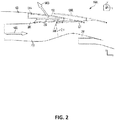
- Fig. 2 illustrates a side cutaway view of an aircraft propulsor in accordance with an example of the disclosure.
- the aircraft propulsor 100 shown in Fig. 2 may include the nacelle 102 with a bullnose 206, the thrust reverser door 124, a core engine 248, a thrust reverser cascade 210, a cascade support ring 208, a thrust reverser aperture 132, and a blocker door 214.
- the core engine 248 and/or the nacelle 102 may define, at least in part, a bypass flow path 256. Air energized by the fan 136 may flow through the bypass flow path 256.
- the energized air may flow out of an exhaust of the nacelle 102, but during thrust reversing, the energized air may be diverted by the blocker door 213 and flow out of nacelle 102 through the thrust reverser cascade and the thrust reverser aperture 132.
- the nacelle 102 may be similar to the nacelle described in Fig. 1 .
- the nacelle 102 in Fig. 2 may additionally include the bullnose 206.
- the bullnose 206 may be any structure that may couple to an end of the thrust reverser cascade 210.
- the bullnose 206 may extend from another portion of the nacelle 102 and may form a ledge of the nacelle 102.
- at least the portion of the bullnose 206 facing the core engine 248 may include a smoothly radius'd surface. Such a radius'd surface may allow for smooth airflow from the bypass flow path 256 through the thrust reverser cascade 210 and, accordingly, allow for higher massflow through the thrust reverser cascade 210.
- a surface of the thrust reverser door 124 may be configured to be placed adjacent to or coupled to a portion of the bullnose 206 when in the closed position. As such, the thrust reverser door 124 may, when in the closed position, form a smooth or substantially smooth surface with an interior surface of the nacelle 102 to allow for smooth airflow within the aircraft propulsor 100 when the thrust reverser door 124 is in the closed position.
- the thrust reverser door 124 may include an inner wall and an outer wall.
- Fig. 2 further illustrates the open and closed positions of the thrust reverser door 124.
- the thrust reverser door 124 may be in an open position 124B as well as a closed position 124A.
- the thrust reverser door 124 in other examples may be configured to be in other positions.
- other examples may include non-translating thrust reverser doors (e.g., thrust reverser doors that may rotate between an open and a closed position, as well as other positions) as well as thrust reverser doors that open and close in other manners (e.g., through shutters, through the deployment of air deflectors, or through other manners).
- the thrust reverser door 124 may allow air to flow through the bypass flow path 256 of the aircraft propulsor 100 and exit the bypass flow path 256 through an exhaust to provide thrust.
- the bypass flow path 256 may be defined, at least in part, by portions of the core engine 248 and/or the nacelle 102.
- the air flowing through the bypass flowpath 256 may be energized by the fan 136, may generally flow in airflow direction 140A, and may provide thrust (or reverse thrust) to power the aircraft that the aircraft propulsor 100 is attached to.
- the core engine 248 may power the fan 136 and the fan 136 may energize the air flowing through the bypass flowpath 256.
- the blocker door 214 may be positioned to not block or minimally block (e.g., be a restriction of less than 5% of total airflow within the bypass flow path 256) airflow within the bypass flow path 256.
- the thrust reverser door 124 may allow air to flow through the thrust reverser aperture 132.
- the blocker door 214 may also be moved into a position to block at least a portion of the bypass flow path 256 to divert airflow within the bypass flow path 256 through the thrust reverser aperture 132.
- Such diverted airflow may at least in part flow in airflow direction 140B or in the general direction of airflow direction 140B. Air flowing in airflow direction 140B may provide reverse thrust.
- the linear thrust reverser cascade 210 shown in Fig. 2 may be a linear thrust reverser cascade.
- Fig. 2 shows a side cutaway view of the thrust reverser cascade 210
- the thrust reverser cascade 210 may be circumferentially disposed and/or offset from, for example, the core engine 248 or another portion of the aircraft propulsor 100.
- the thrust reverser cascade 210 may "wrap around" the core engine 248.
- the thrust reverser cascade 210 may extend linearly, or substantially linearly, from the bullnose 206 to the cascade support ring 208.
- the bullnose 206 and/or the cascade support ring 208 may be coupled to the thrust reverser cascade 210.
- the bullnose 206 and/or the cascade support ring 208 may support and/or hold in place the thrust reverser cascade 210.
- the cascade support ring 208 may be attached to other structural features of the aircraft propulsor 100.
- Fig. 3 illustrates a side cutaway view of a honeycomb structure and a honeycomb fastening system in accordance with an example of the disclosure.
- Fig. 3 includes a honeycomb structure with a first facesheet 360, a second facesheet 362, and a honeycomb core 358, a honeycomb fastening system with a male spool 350, a female spool 352, a bolt 354, and a nut 356. Additionally, various examples of Fig. 3 may also include a shim 366, a secondary structure 368, and a spacer plate 364.
- the honeycomb structure includes the first facesheet 360, the second facesheet 362, and the honeycomb core 358.
- the honeycomb core 358 is disposed between the first facesheet 360 and the second facesheet 362.
- additional items may be disposed between the first facesheet 360, the honeycomb core 358, and/or the second facesheet 362.
- the first facesheet 360, the second facesheet 362, and/or the honeycomb core 358 may all be constructed from the same material, but other examples may construct the first facesheet 360, the second facesheet 362, and/or the honeycomb core 358 from a plurality of different materials.
- Such materials may be, for example, a metal such as steel, aluminum, titanium, tungsten, copper, and other metals, a composite such as fiberglass, carbon fiber, Kevlar, and other composites, a plastic, wood, glass, and other suitable types of material.
- a metal such as steel, aluminum, titanium, tungsten, copper, and other metals
- a composite such as fiberglass, carbon fiber, Kevlar, and other composites
- plastic wood, glass, and other suitable types of material.
- the first facesheet 360, the honeycomb core 358, and the second facesheet 362 may all be constructed from, at least, titanium.
- the first facesheet 360 and the second facesheet 362 may be constructed from a combination of carbon fiber and Kevlar, but the honeycomb core 358 may be constructed from only carbon fiber.
- the coefficient of thermal expansion of the honeycomb structure and the male spool and/or the female spool may be substantially similar (e.g., within 20% or less).
- the honeycomb structure may be comprised of the same material as that of the male spool and/or the female spool (e.g., all are made from titanium) or may be comprised of materials that have substantially similar coefficients of thermal expansion.
- the male spool 350 includes a male spool body. At least a portion of the male spool body may be cylindrical or substantially cylindrical.
- the male spool body includes an external threaded portion disposed on a cylindrical or substantially cylindrical portion of the male spool body.
- the male spool body includes a male flange portion. The male flange portion is configured to, when coupled to the honeycomb structure, transfer force to the first facesheet 360 of the honeycomb structure.
- the male spool 350 may be further described in Fig. 4 .
- the female spool 352 includes a female spool body. At least a portion of the female spool body may be cylindrical or substantially cylindrical.
- the female spool body includes an external threaded portion disposed on a cylindrical or substantially cylindrical portion of the female spool body. Additionally, the female spool body includes a female flange portion. The female flange portion is configured to, when coupled to the honeycomb structure, transfer force to the second facesheet 362 of the honeycomb structure.
- the female spool 352 may be further described in Fig. 5 .
- the male spool 350 and the female spool 352 may be coupled by threading together the external and internal threaded portions.
- the male spool 350 and the female spool 352 may be coupled without, for example, welding, potting, or crushing of the honeycomb core 358.
- fastening of the male spool 350 and the female spool 352 may be accomplished repeatably at a high rate of production with a minimum of inspection. The fastening may not damage the honeycomb structure (e.g., may not crush and/or plastically deform the honeycomb core 358).
- the fastening of the male spool 350 and the female spool 352 may allow the fastening system to withstand higher temperatures such as 300 degrees Celsius or less, 500 degrees Celsius or less, 1,000 degrees Celsius or less, or more than 1,000 degrees Celsius.
- the fastening system may not include potting compounds or other adhesives that may melt or weaken at such high temperatures. The lack of such adhesives may allow the fastening system to withstand higher temperatures.
- the thrust reverser door 124 may include a portion, such as the inner wall, that may be located close or face the core engine 248. Such portions may be exposed to high temperatures and, accordingly, the fastening system disclosed herein may withstand such higher temperatures.
- the spools may be threaded together to a specified torque value. Force from threading together the spools and/or from any fasteners installed using the spools (e.g., the bolt 354) may be transferred, via the male flange portion and/or the female flange portion, to the honeycomb structure. As such, the male flange portion of the male spool 350 may transfer force received by the male spool 350 to the first facesheet 360 and the female flange portion of the female spool 352 may transfer force received by the female spool 352 to the second facesheet 362.
- load may thus be transferred from the bolt 354 through the spool walls and into the first facesheet 360 and/or the second facesheet 362.
- the male flange portion and/or the female flange portion may be sized such that the load may be transferred over a sufficiently large area of the first facesheet 360 and/or the second facesheet 362 to prevent deformation and/or plastic deformation of the honeycomb core 358.
- Certain examples may also include the shim 366.
- the shim 366 may, for example, cover one of the male spool 350 and/or the female spool 352.
- the female spool 352 may be inserted into an aperture of the second facesheet 362.
- the shim 366 may then be placed, assembled, and/or coupled to the second facesheet 362.
- the shim 366 may cover at least a portion of the female spool 352.
- the shim 366 may, for example, further hold the female spool 352 in place and/or may be a heat shield for the honeycomb structure and/or the female spool 352.
- Other examples may include additional shims that may cover the other of the male spool 350 and/or the female spool 352.
- the spacer plate 364 may be the same or a similar thickness to that of the flange portion of the female spool 352.
- the spacer plate 364 may allow the shim 366 to be laid flush on top of the spacer plate 364.
- the spacer plate 364 may include a cut-out configured to contain the flange portion of the female spool 352. As such, the shim 366 may rest on the spacer plate 364 and the female spool 352.
- the nut 356 may be coupled to the secondary structure 368.
- the secondary structure 368 may be, for example, a component of the aircraft, the aircraft propulsor 100, and/or the thrust reverser door 124.
- the secondary structure 368 may be attached to the honeycomb structure.
- the bolt 354 may include a head and a shank and may be inserted into the through holes of the male spool 350 and the female spool 352 and then through an aperture of the secondary structure 368.
- the nut 356 may be attached to the bolt 354 at an end (e.g., a threaded end) to clamp or otherwise couple the secondary structure 368 to the honeycomb structure.
- clamping force from the bolt 354 may be distributed to the male spool 350 and then evenly distributed from parts of the male spool 350 to the honeycomb structure.
- the bolt 354 may be shaped so that, when inserted into the male spool 350, the head of the bolt 354 is flush with a surface of the male spool 350.
- the bolt 354 and/or the nut 356 may additionally include one or more washers or other apparatuses to more evenly distribute the clamping force.
- load may be transferred from, for example, the secondary structure 368 to the honeycomb structure via the female spool 352.
- the secondary structure 368 may be a highly loaded component of an aircraft. As such, the load from the secondary structure 368 may be transferred into the honeycomb structure via the fastening system.
- the shim 366 and/or the spacer plate 364 may aid in the transfer of load from the secondary structure 368 by closing gaps between the secondary structure 368 and the honeycomb structure and thus allow for a load-path from the secondary structure 368 to the honeycomb structure. Additionally, the shim 366 and/or the spacer plate 364 reduce preload within the fastening system.
- the shim 366 may also allow for accurate positioning of the secondary structure 368 relative to the fastening system and/or another component of the aircraft or aircraft propulsor by, for example, allowing for distances between such components to be changed via the stacking or taking away of shims.
- Fig. 4 illustrates a side cutaway view of a male spool in accordance with the disclosure.
- the male spool 350 may include a male spool body.
- the male spool body may include a male flange portion 470, a male shank portion 472, a male through hole 474, a chamfer 476, and a male shoulder 478.
- the male shank portion 472 may be located on a first end of the male spool body.
- the male shank portion 472 may be inserted into an aperture within a honeycomb structure.
- the male shank portion 472 may be threaded to, for example, screw onto a threaded portion of the female spool 352.
- the male flange portion 470 may located on a second end of the male spool body and may be configured to couple to a facesheet (e.g., the first facesheet 360) of a honeycomb structure.
- the male flange portion 470 may evenly distribute force from the male spool 350 to the honeycomb structure.
- the male flange portion 470 may, for example, be sized responsive to an expected force distributed to the male spool 350 such that the expected force is transferred to a sufficiently large area of the honeycomb structure so as to prevent significant and/or plastic deformation of the honeycomb structure and/or the honeycomb core 358.
- male flange diameter 492 may be expressed as a ratio of the male shank diameter 490.
- the ratio may be less than 2 to 1, less than 3 to 1, less than 5 to 1, less than 10 to 1, less than 20 to 1, or 20 to 1 or more.
- the ratio may be expressed as a ratio of the cross sectional area between the male flange portion 470 and the male shank portion 472.
- the male flange portion 470 may be configured to transfer out-of-plane loads (e.g., clamping loads and/or tension loads transferred through the bolt, nut, and/or other structures such as the secondary structure 368).
- the male flange portion 470 may receive such loads and transfer the loads to the honeycomb structure (e.g., the first facesheet 360).
- the through hole 474 may be disposed within the male spool body.
- the through hole 474 may allow a portion of the bolt 354 to pass through the male spool 350.
- the through hole 474 may extend from the first end of the male spool body to the second end.
- the through hole 474 may be substantially smooth so that the bolt 354 may pass through the through hole 474 without threading into the through hole 474.
- the male spool 350 may additionally include the chamfer 350 on one or both ends of the through hole 474. The chamfer 350 may allow for the head of the bolt 354 to be flush when inserted into the male spool 350.
- the male spool 350 may include the male shoulder 478.
- the male shoulder 478 may, for example, be sized to aid in locating the male spool 350 within an aperture of the honeycomb structure.
- Certain examples of the male shoulder 478 may include chamfers, rounds, and/or other features to aid in the insertion of the male spool 350 into the aperture.
- the male shoulder 478 may transfer in-plane loads (e.g., bearing loads) received by the male spool 350 to a honeycomb structure coupled to the male spool 350. Transferring such loads through the male shoulder 478 may decrease and/or eliminate bending of the male spool 350 and/or any bolt or nut attached to the male spool 350.
- the height of the male shoulder 478 i.e., its dimension in the y-axis as shown in Fig. 4
- certain sides of the male shoulder 478 may be parallel to certain sides of the aperture of the facesheet that the male spool 350 is configured to couple to.
- the diameter of the male shoulder 478 may be sized according to the expected load to transfer force over a sufficiently large bearing area such that no deformation or plastic deformation of the facesheet and/or any other portion of the honeycomb structure results from the transfer of such force.
- the diameter of the male shoulder 478 may be expressed as a ratio to the diameter of the male shank portion 472. In certain examples, the ratio may be less than 1.1 to 1, less than 1.5 to 1, less than 2 to 1, less than 3 to 1, less than 5 to 1, or 5 to 1 or more.
- Fig. 5 illustrates a side cutaway view of a female spool in accordance with examples of the disclosure.
- the female spool 352 may include a female spool body.
- the female spool body may include a female flange portion 580, a female shank portion 582, a female through hole 584, and a female shoulder 586.
- the female shank portion 582 may be located on a first end of the female spool body.
- the female shank portion 582 may be threaded and may be configured to be inserted into an aperture within a honeycomb structure and threaded onto a threaded portion of the male spool 350.
- the threaded portion of the female shank portion 582 may be threaded to match the threaded portion of the male shank portion 472. Threading together the male spool 350 and the female spool 352 may allow for the male spool 350 and the female spool 352 to be coupled together and mechanically fastened to the honeycomb structure.
- the male spool 350 and the female spool 352 may be mechanically fastened to the honeycomb structure without the use of adhesives such as potting compounds and/or without the use of welding or other secondary assembly steps.
- the female flange portion 580 may located on a second end of the female spool body and may be configured to couple to a facesheet (e.g., the second facesheet 362) of a honeycomb structure.
- the female flange portion 580 may evenly distribute force from the female spool 352 to the honeycomb structure. Additionally, the female flange portion 580 may, for example, be sized responsive to an expected force distributed to the female spool 352 such that the expected force is transferred to a sufficiently large area of the honeycomb structure so as to prevent significant and/or plastic deformation of the honeycomb structure and/or the honeycomb core 358.
- female flange diameter 594 may be expressed as a ratio of the female shank diameter 596.
- the ratio may be less than 2 to 1, less than 3 to 1, less than 5 to 1, less than 10 to 1, less than 20 to 1, or 20 to 1 or more.
- the ratio may be expressed as a ratio of the cross sectional area between the female flange portion 580 and the female shank portion 582.
- the through hole 584 may be disposed within the female spool body similar to the through hole 474 of the male spool body.
- the through hole 584 may allow a portion of the bolt 354 to pass through the female spool 352.
- the through hole 584 may extend from the first end of the female spool body to the second end.
- the through hole 584 may be substantially smooth so that the bolt 354 may pass through the through hole 584 without threading into the through hole 584.
- the through hole 584 may include a through hole shoulder 588.
- the through hole shoulder 588 may be configured to transfer loads such as bearing loads experienced by the bolt to the honeycomb structure via the female spool 352.
- the through hole shoulder 588 may include an inner diameter similar to the diameter of the shank of the bolt that the through hole 584 is configured to receive.
- the bolt may, when loaded, moved, or deflected, contact the through hole shoulder 588 and transfer load to the through hole shoulder 588.
- load may be transferred from the bolt to the through hole shoulder 588 and to the honeycomb structure.
- load transfer may prevent significant bending of the bolt under bolt.
- the through hole 474 of the male spool 350 may alternatively or additionally include a through hole shoulder.
- the through hole 474 of the male spool 350 may be sized to act as a shoulder to transfer load from and prevent deformation or substantial deformation of the bolt.
- the female spool 352 may also include, in certain examples, the female shoulder 586.
- the female shoulder 586 may, for example, be sized to aid in locating the female spool 352 within an aperture of the honeycomb structure.
- Certain examples of the female shoulder 586 may include features similar to that of the male shoulder 478, including chamfers, rounds, and/or other features to aid in the insertion of the female spool 352 into the aperture.
- the female shoulder 586 may transfer in-plane loads (e.g., bearing loads) received by the female spool to a honeycomb structure coupled to the female spool. Transferring such loads may decrease and/or eliminate bending of the female spool and/or any bolt or nut attached to the female spool.
- the height of the female shoulder 586 may be equal to or greater than the thickness of the facesheet that the female spool 352 is configured to couple to. Additionally, in certain such examples, certain sides of the female shoulder 586 may be parallel to certain sides of the aperture of the facesheet. Also, the diameter of the female shoulder 586 and/or the through hole shoulder 588 may be sized according to the expected load to transfer force over a sufficiently large bearing area such that no deformation or plastic deformation of the facesheet results from the transfer of such force. In certain examples, the diameter of the female shoulder 586 may be expressed as a ratio to the diameter of the female shank portion 582. In certain examples, the ratio may be less than 1.1 to 1, less than 1.5 to 1, less than 2 to 1, less than 3 to 1, less than 5 to 1, or 5 to 1 or more.
- Fig. 6 is a flowchart detailing assembly of a secondary structure to a honeycomb structure in accordance with an example of the disclosure.
- a male spool may be inserted into an aperture of the honeycomb structure.
- a female spool may be inserted into the aperture of the honeycomb structure.
- the male spool and the female spool may be coupled together by threading together thread portions of the male spool and the female spool.
- the male spool and the female spool may be threaded together to a specified torque to couple to and distribute load to the honeycomb structure.
- the male spool and the female spool may be coupled together without adhesives, welding, or other techniques that may be more labor intensive and/or may lead to failure at high temperatures.
- a bolt may be inserted into a through hole of the male spool and/or the female spool.
- the bolt may be inserted without threading into the through holes of the male spool and/or the female spool.
- the bolt may include a head and a shank. The head may contact one end of the through hole(s).
- a structure of the aircraft e.g., a structure associated with a thrust reverser
- the bolt may pass through the through hole(s) to be inserted within an aperture of the structure.
- a nut may be threaded onto the bolt.
- the nut may hold the structure in place when the threaded onto the bolt.
- the structure may be disposed between the honeycomb structure and the nut.
- the nut may be threaded to a specific torque value to securely couple the structure to the honeycomb structure.
- the specific torque value may crush the honeycomb core 358 of the composite honeycomb structure, even with washers transferring load.
- the fastening system may provide a stiff column to transfer load from the torque and, thus, avoid crushing and/or plastic deformation of the honeycomb structure.
Landscapes
- Engineering & Computer Science (AREA)
- General Engineering & Computer Science (AREA)
- Mechanical Engineering (AREA)
- Chemical & Material Sciences (AREA)
- Combustion & Propulsion (AREA)
- Aviation & Aerospace Engineering (AREA)
- Connection Of Plates (AREA)
- Laminated Bodies (AREA)
Abstract
Description
- The disclosure relates generally to aircraft and more specifically to aircraft thrust reversers and to distribution of loads through honeycomb panels.
- Aircraft propulsor thrust reversers often include an inner wall and an outer wall. The inner wall may be located close to the core engine of the aircraft propulsor. As core engines of aircraft propulsors increase in power, the amount of heat generated by the engines also typically increases. The inner wall, located close to the core engine, may also experience higher temperature levels. The inner walls may be attached to other structures of the aircraft. However, traditional techniques of creating coupling features for attaching of the inner walls to the other structures of the aircraft may be ineffective due to the high temperatures.
- Systems and methods are disclosed herein for thrust reverser honeycomb panel load distribution. In certain examples an aircraft propulsor may be provided. The aircraft propulsor may include a core engine and a thrust reverser. The thrust reverser may include an inner wall located proximate the core engine. The inner wall may include a honeycomb structure including a first facesheet, a second facesheet, a honeycomb core disposed between the first facesheet and the second facesheet, and an aperture, and a fastening system disposed within the aperture. The fastening system may include a male spool and a female spool. The male spool may include a male spool body, where an external threaded portion is disposed on at least a first end of the male spool body, a male through hole is disposed within the male spool body, and a male flange portion is disposed on a second end of the male spool body, is coupled to the first facesheet, and is configured to distribute load to the honeycomb structure. The female spool may include a female spool body, where a internal threaded portion is disposed on at least a first end of the female spool body and coupled to the external threaded portion to fasten the male spool and the female spool to the honeycomb structure, a female through hole is disposed within the female spool body, and a female flange is portion disposed on a second end of the female spool body, is coupled to the second facesheet, and is configured to distribute load to the honeycomb structure.
- In certain other embodiments, a fastening system for a structure may be provided. The fastening system may include a male spool and a female spool. The male spool may include a male spool body where an external threaded portion is disposed on at least a first end of the male spool body, a male through hole is disposed within the male spool body, and a male flange portion is disposed on a second end of the male spool body and is configured to couple to a first facesheet of a honeycomb structure and distribute load to the honeycomb structure when the male flange portion is coupled to the first facesheet. The female spool may include a female spool body where an internal threaded portion is disposed on at least a first end of the female spool body and is configured to couple to the external threaded portion to fasten the male spool and the female spool to the honeycomb structure, a female through hole is disposed within the female spool body, and a female flange portion is disposed on a second end of the female spool body and is configured to couple to a second facesheet of the honeycomb structure and distribute load to the honeycomb structure when the female flange portion is coupled to the second facesheet.
- The scope of the invention is defined by the claims, which are incorporated into this section by reference. A more complete understanding of the disclosure will be afforded to those skilled in the art, as well as a realization of additional advantages thereof, by a consideration of the following detailed description of one or more implementations. Reference will be made to the appended sheets of drawings that will first be described briefly.
-
-
Fig. 1 illustrates a perspective view of an aircraft propulsor in accordance with an example of the disclosure. -
Fig. 2 illustrates a side cutaway view of an aircraft propulsor in accordance with an example of the disclosure. -
Fig. 3 illustrates a side cutaway view of a honeycomb structure and a honeycomb fastening system in accordance with an example of the disclosure. -
Fig. 4 illustrates a side cutaway view of a male spool in accordance with the disclosure. -
Fig. 5 illustrates a side cutaway view of a female spool in accordance with examples of the disclosure. -
Fig. 6 is a flowchart detailing assembly of a secondary structure to a honeycomb structure in accordance with an example of the disclosure. - Examples of the disclosure and their advantages are best understood by referring to the detailed description that follows. It should be appreciated that like reference numerals are used to identify like elements illustrated in one or more of the figures.
- Systems and techniques for a fastening system for distribution of point loads through honeycomb panels are described in the disclosure herein in accordance with one or more examples. In certain examples, the honeycomb panels may be panels of an aircraft propulsor. The honeycomb panels may be, for example, a portion of a thrust reverser of the aircraft propulsor. In such an example, the honeycomb panels may be an outer wall, an inner wall, or another portion of the thrust reverser.
- The fastening system may include a male spool and a female spool. The male spool may include a male spool body that may include an external threaded portion disposed on a cylindrical or substantially cylindrical portion of the male spool body and a male flange portion. The female spool may include a female spool body that may include an internal threaded portion disposed on a cylindrical or substantially cylindrical portion of the female spool body and a female flange portion. The male spool may be inserted into an aperture of the honeycomb panel from one end, while the female spool may be inserted into the aperture from the other end. The male spool and the female spool may be coupled to each other by, for example, being threaded onto each other. The male flange portion may contact a first facesheet of the honeycomb structure while the female flange portion may contact a second facesheet of the honeycomb structure opposite that of the first facesheet. The male spool and the female spool may be threaded to a specified torque value. Force imparted by the fastening of the male spool to the female spool and/or from fasteners tightened to the male spool and/or the female spool may be transferred to the honeycomb structure.
-
Fig. 1 illustrates a perspective view of an aircraft propulsor in accordance with an example of the disclosure.Aircraft propulsor 100 may include anacelle 102, athrust reverser door 124, and afan 136. In the example shown inFig. 1 , thenacelle 102 may contain thefan 136, but other examples of the aircraft propulsor may arrange the fan so that the fan is not contained by the nacelle (e.g., in, for example, a turboprop configuration). Thefan 136 may intake and/or energize air flowing into thenacelle 102, such as in anairflow direction 140A. Air that flows into thenacelle 102 viaairflow direction 140A may flow through various internal flow paths within thenacelle 102. When theaircraft propulsor 100 is in a thrust reversing configuration, air that flows into thenacelle 102 inairflow direction 140A may be redirected to another direction to provide reverse thrust. - When the
aircraft propulsor 100 is normally operating (e.g., providing thrust), the thrustreverser door 124 may be in a closed position that blocks the thrust reverser aperture (shown inFig. 2 as thrust reverser aperture 132), sealing or substantially sealing the thrust reverser aperture so that there is no or minimal airflow through thethrust reverser aperture 132. When theaircraft propulsor 100 is in a thrust reversing configuration (e.g., providing reverse thrust to, for example, slow the aircraft 50 that theaircraft propulsor 100 may attached to), the thrustreverser door 124 may be in an open position that does not block thethrust reverser aperture 132, allowing for air to flow through thethrust reverser aperture 132. In certain examples, the thrust reverserdoor 124 may form thethrust reverser aperture 132 when the thrust reverserdoor 124 is in the open configuration. In such an example, there may be nothrust reverser aperture 132 when the thrust reverserdoor 124 is in a closed configuration. -
Fig. 2 illustrates a side cutaway view of an aircraft propulsor in accordance with an example of the disclosure. Theaircraft propulsor 100 shown inFig. 2 may include thenacelle 102 with abullnose 206, thethrust reverser door 124, acore engine 248, athrust reverser cascade 210, acascade support ring 208, athrust reverser aperture 132, and ablocker door 214. Thecore engine 248 and/or thenacelle 102 may define, at least in part, abypass flow path 256. Air energized by thefan 136 may flow through thebypass flow path 256. During normal operations, the energized air may flow out of an exhaust of thenacelle 102, but during thrust reversing, the energized air may be diverted by the blocker door 213 and flow out ofnacelle 102 through the thrust reverser cascade and thethrust reverser aperture 132. - The
nacelle 102 may be similar to the nacelle described inFig. 1 . Thenacelle 102 inFig. 2 may additionally include thebullnose 206. Thebullnose 206 may be any structure that may couple to an end of thethrust reverser cascade 210. In certain examples, thebullnose 206 may extend from another portion of thenacelle 102 and may form a ledge of thenacelle 102. As shown inFig. 2 , at least the portion of thebullnose 206 facing thecore engine 248 may include a smoothly radius'd surface. Such a radius'd surface may allow for smooth airflow from thebypass flow path 256 through thethrust reverser cascade 210 and, accordingly, allow for higher massflow through thethrust reverser cascade 210. A surface of thethrust reverser door 124 may be configured to be placed adjacent to or coupled to a portion of thebullnose 206 when in the closed position. As such, thethrust reverser door 124 may, when in the closed position, form a smooth or substantially smooth surface with an interior surface of thenacelle 102 to allow for smooth airflow within theaircraft propulsor 100 when thethrust reverser door 124 is in the closed position. In certain examples, thethrust reverser door 124 may include an inner wall and an outer wall. -
Fig. 2 further illustrates the open and closed positions of thethrust reverser door 124. As shown, thethrust reverser door 124 may be in anopen position 124B as well as aclosed position 124A. The thrust reverserdoor 124 in other examples may be configured to be in other positions. Additionally, other examples may include non-translating thrust reverser doors (e.g., thrust reverser doors that may rotate between an open and a closed position, as well as other positions) as well as thrust reverser doors that open and close in other manners (e.g., through shutters, through the deployment of air deflectors, or through other manners). - In the
closed position 124A, thethrust reverser door 124 may allow air to flow through thebypass flow path 256 of theaircraft propulsor 100 and exit thebypass flow path 256 through an exhaust to provide thrust. Thebypass flow path 256 may be defined, at least in part, by portions of thecore engine 248 and/or thenacelle 102. The air flowing through thebypass flowpath 256 may be energized by thefan 136, may generally flow inairflow direction 140A, and may provide thrust (or reverse thrust) to power the aircraft that theaircraft propulsor 100 is attached to. Thecore engine 248 may power thefan 136 and thefan 136 may energize the air flowing through thebypass flowpath 256. - When the
thrust reverser door 124 is in theclosed position 124A, theblocker door 214 may be positioned to not block or minimally block (e.g., be a restriction of less than 5% of total airflow within the bypass flow path 256) airflow within thebypass flow path 256. - In the
open position 124B, thethrust reverser door 124 may allow air to flow through thethrust reverser aperture 132. In certain examples, when thethrust reverser door 124 is in theopen position 124B, theblocker door 214 may also be moved into a position to block at least a portion of thebypass flow path 256 to divert airflow within thebypass flow path 256 through thethrust reverser aperture 132. Such diverted airflow may at least in part flow inairflow direction 140B or in the general direction ofairflow direction 140B. Air flowing inairflow direction 140B may provide reverse thrust. - Diverted airflow may flow through the
thrust reverser cascade 210. The linearthrust reverser cascade 210 shown inFig. 2 may be a linear thrust reverser cascade. ThoughFig. 2 shows a side cutaway view of thethrust reverser cascade 210, thethrust reverser cascade 210 may be circumferentially disposed and/or offset from, for example, thecore engine 248 or another portion of theaircraft propulsor 100. E.g., thethrust reverser cascade 210 may "wrap around" thecore engine 248. Additionally, thethrust reverser cascade 210 may extend linearly, or substantially linearly, from thebullnose 206 to thecascade support ring 208. Thebullnose 206 and/or thecascade support ring 208 may be coupled to thethrust reverser cascade 210. Thebullnose 206 and/or thecascade support ring 208 may support and/or hold in place thethrust reverser cascade 210. In certain such examples, thecascade support ring 208 may be attached to other structural features of theaircraft propulsor 100. -
Fig. 3 illustrates a side cutaway view of a honeycomb structure and a honeycomb fastening system in accordance with an example of the disclosure.Fig. 3 includes a honeycomb structure with afirst facesheet 360, asecond facesheet 362, and ahoneycomb core 358, a honeycomb fastening system with amale spool 350, afemale spool 352, abolt 354, and anut 356. Additionally, various examples ofFig. 3 may also include ashim 366, asecondary structure 368, and aspacer plate 364. - The honeycomb structure includes the
first facesheet 360, thesecond facesheet 362, and thehoneycomb core 358. Thehoneycomb core 358 is disposed between thefirst facesheet 360 and thesecond facesheet 362. In certain other examples, additional items may be disposed between thefirst facesheet 360, thehoneycomb core 358, and/or thesecond facesheet 362. In certain examples, thefirst facesheet 360, thesecond facesheet 362, and/or thehoneycomb core 358 may all be constructed from the same material, but other examples may construct thefirst facesheet 360, thesecond facesheet 362, and/or thehoneycomb core 358 from a plurality of different materials. Such materials may be, for example, a metal such as steel, aluminum, titanium, tungsten, copper, and other metals, a composite such as fiberglass, carbon fiber, Kevlar, and other composites, a plastic, wood, glass, and other suitable types of material. For example, in certain examples, thefirst facesheet 360, thehoneycomb core 358, and thesecond facesheet 362 may all be constructed from, at least, titanium. In certain other examples, thefirst facesheet 360 and thesecond facesheet 362 may be constructed from a combination of carbon fiber and Kevlar, but thehoneycomb core 358 may be constructed from only carbon fiber. In certain such examples, the coefficient of thermal expansion of the honeycomb structure and the male spool and/or the female spool may be substantially similar (e.g., within 20% or less). Accordingly, the honeycomb structure may be comprised of the same material as that of the male spool and/or the female spool (e.g., all are made from titanium) or may be comprised of materials that have substantially similar coefficients of thermal expansion. - The
male spool 350 includes a male spool body. At least a portion of the male spool body may be cylindrical or substantially cylindrical. The male spool body includes an external threaded portion disposed on a cylindrical or substantially cylindrical portion of the male spool body. Additionally, the male spool body includes a male flange portion. The male flange portion is configured to, when coupled to the honeycomb structure, transfer force to thefirst facesheet 360 of the honeycomb structure. Themale spool 350 may be further described inFig. 4 . - The
female spool 352 includes a female spool body. At least a portion of the female spool body may be cylindrical or substantially cylindrical. The female spool body includes an external threaded portion disposed on a cylindrical or substantially cylindrical portion of the female spool body. Additionally, the female spool body includes a female flange portion. The female flange portion is configured to, when coupled to the honeycomb structure, transfer force to thesecond facesheet 362 of the honeycomb structure. Thefemale spool 352 may be further described inFig. 5 . - The
male spool 350 and thefemale spool 352 may be coupled by threading together the external and internal threaded portions. In certain embodiments, themale spool 350 and thefemale spool 352 may be coupled without, for example, welding, potting, or crushing of thehoneycomb core 358. As such, fastening of themale spool 350 and thefemale spool 352 may be accomplished repeatably at a high rate of production with a minimum of inspection. The fastening may not damage the honeycomb structure (e.g., may not crush and/or plastically deform the honeycomb core 358). Additionally, the fastening of themale spool 350 and thefemale spool 352 may allow the fastening system to withstand higher temperatures such as 300 degrees Celsius or less, 500 degrees Celsius or less, 1,000 degrees Celsius or less, or more than 1,000 degrees Celsius. As such, the fastening system may not include potting compounds or other adhesives that may melt or weaken at such high temperatures. The lack of such adhesives may allow the fastening system to withstand higher temperatures. - The ability to withstand higher temperatures may be beneficial in certain applications. For example, the
thrust reverser door 124 may include a portion, such as the inner wall, that may be located close or face thecore engine 248. Such portions may be exposed to high temperatures and, accordingly, the fastening system disclosed herein may withstand such higher temperatures. - The spools may be threaded together to a specified torque value. Force from threading together the spools and/or from any fasteners installed using the spools (e.g., the bolt 354) may be transferred, via the male flange portion and/or the female flange portion, to the honeycomb structure. As such, the male flange portion of the
male spool 350 may transfer force received by themale spool 350 to thefirst facesheet 360 and the female flange portion of thefemale spool 352 may transfer force received by thefemale spool 352 to thesecond facesheet 362. In examples where thebolt 354 and thenut 356 are fastened to the spools, load may thus be transferred from thebolt 354 through the spool walls and into thefirst facesheet 360 and/or thesecond facesheet 362. The male flange portion and/or the female flange portion may be sized such that the load may be transferred over a sufficiently large area of thefirst facesheet 360 and/or thesecond facesheet 362 to prevent deformation and/or plastic deformation of thehoneycomb core 358. - Certain examples may also include the
shim 366. Theshim 366 may, for example, cover one of themale spool 350 and/or thefemale spool 352. In the example illustrated inFig. 3 , thefemale spool 352 may be inserted into an aperture of thesecond facesheet 362. Theshim 366 may then be placed, assembled, and/or coupled to thesecond facesheet 362. Theshim 366 may cover at least a portion of thefemale spool 352. Theshim 366 may, for example, further hold thefemale spool 352 in place and/or may be a heat shield for the honeycomb structure and/or thefemale spool 352. Other examples may include additional shims that may cover the other of themale spool 350 and/or thefemale spool 352. - Certain examples may include the
spacer plate 364. Thespacer plate 364 may be the same or a similar thickness to that of the flange portion of thefemale spool 352. Thespacer plate 364 may allow theshim 366 to be laid flush on top of thespacer plate 364. Thespacer plate 364 may include a cut-out configured to contain the flange portion of thefemale spool 352. As such, theshim 366 may rest on thespacer plate 364 and thefemale spool 352. - The
nut 356 may be coupled to thesecondary structure 368. Thesecondary structure 368 may be, for example, a component of the aircraft, theaircraft propulsor 100, and/or thethrust reverser door 124. Thesecondary structure 368 may be attached to the honeycomb structure. As such, thebolt 354 may include a head and a shank and may be inserted into the through holes of themale spool 350 and thefemale spool 352 and then through an aperture of thesecondary structure 368. Thenut 356 may be attached to thebolt 354 at an end (e.g., a threaded end) to clamp or otherwise couple thesecondary structure 368 to the honeycomb structure. In certain such examples, clamping force from thebolt 354 may be distributed to themale spool 350 and then evenly distributed from parts of themale spool 350 to the honeycomb structure. In the embodiment shown inFig. 3 , thebolt 354 may be shaped so that, when inserted into themale spool 350, the head of thebolt 354 is flush with a surface of themale spool 350. In certain examples, thebolt 354 and/or thenut 356 may additionally include one or more washers or other apparatuses to more evenly distribute the clamping force. Additionally, load may be transferred from, for example, thesecondary structure 368 to the honeycomb structure via thefemale spool 352. - In certain examples, the
secondary structure 368 may be a highly loaded component of an aircraft. As such, the load from thesecondary structure 368 may be transferred into the honeycomb structure via the fastening system. Theshim 366 and/or thespacer plate 364 may aid in the transfer of load from thesecondary structure 368 by closing gaps between thesecondary structure 368 and the honeycomb structure and thus allow for a load-path from thesecondary structure 368 to the honeycomb structure. Additionally, theshim 366 and/or thespacer plate 364 reduce preload within the fastening system. In certain examples, theshim 366 may also allow for accurate positioning of thesecondary structure 368 relative to the fastening system and/or another component of the aircraft or aircraft propulsor by, for example, allowing for distances between such components to be changed via the stacking or taking away of shims. -
Fig. 4 illustrates a side cutaway view of a male spool in accordance with the disclosure. Themale spool 350 may include a male spool body. The male spool body may include amale flange portion 470, amale shank portion 472, a male throughhole 474, achamfer 476, and amale shoulder 478. - The
male shank portion 472 may be located on a first end of the male spool body. Themale shank portion 472 may be inserted into an aperture within a honeycomb structure. Themale shank portion 472 may be threaded to, for example, screw onto a threaded portion of thefemale spool 352. - The
male flange portion 470 may located on a second end of the male spool body and may be configured to couple to a facesheet (e.g., the first facesheet 360) of a honeycomb structure. Themale flange portion 470 may evenly distribute force from themale spool 350 to the honeycomb structure. Themale flange portion 470 may, for example, be sized responsive to an expected force distributed to themale spool 350 such that the expected force is transferred to a sufficiently large area of the honeycomb structure so as to prevent significant and/or plastic deformation of the honeycomb structure and/or thehoneycomb core 358. For example, where themale flange portion 470 and themale shank portion 472 are substantially circular in cross section,male flange diameter 492 may be expressed as a ratio of themale shank diameter 490. In certain embodiments, the ratio may be less than 2 to 1, less than 3 to 1, less than 5 to 1, less than 10 to 1, less than 20 to 1, or 20 to 1 or more. In examples where themale flange portion 470 and/or themale shank portion 472 are not substantially circular in cross section, the ratio may be expressed as a ratio of the cross sectional area between themale flange portion 470 and themale shank portion 472. - In certain examples, the
male flange portion 470 may be configured to transfer out-of-plane loads (e.g., clamping loads and/or tension loads transferred through the bolt, nut, and/or other structures such as the secondary structure 368). Themale flange portion 470 may receive such loads and transfer the loads to the honeycomb structure (e.g., the first facesheet 360). - The through
hole 474 may be disposed within the male spool body. The throughhole 474 may allow a portion of thebolt 354 to pass through themale spool 350. The throughhole 474 may extend from the first end of the male spool body to the second end. In certain examples, the throughhole 474 may be substantially smooth so that thebolt 354 may pass through the throughhole 474 without threading into the throughhole 474. In examples where themale spool 350 is configured to receive a bolt with a head configured to be flush with themale spool 350, themale spool 350 may additionally include thechamfer 350 on one or both ends of the throughhole 474. Thechamfer 350 may allow for the head of thebolt 354 to be flush when inserted into themale spool 350. - Certain examples of the
male spool 350 may include themale shoulder 478. Themale shoulder 478 may, for example, be sized to aid in locating themale spool 350 within an aperture of the honeycomb structure. Certain examples of themale shoulder 478 may include chamfers, rounds, and/or other features to aid in the insertion of themale spool 350 into the aperture. - In certain examples, the
male shoulder 478 may transfer in-plane loads (e.g., bearing loads) received by themale spool 350 to a honeycomb structure coupled to themale spool 350. Transferring such loads through themale shoulder 478 may decrease and/or eliminate bending of themale spool 350 and/or any bolt or nut attached to themale spool 350. In certain examples, the height of the male shoulder 478 (i.e., its dimension in the y-axis as shown inFig. 4 ) may be equal to or greater than the thickness of the facesheet that themale spool 350 is configured to couple to. In certain such examples, certain sides of themale shoulder 478 may be parallel to certain sides of the aperture of the facesheet that themale spool 350 is configured to couple to. Additionally, the diameter of themale shoulder 478 may be sized according to the expected load to transfer force over a sufficiently large bearing area such that no deformation or plastic deformation of the facesheet and/or any other portion of the honeycomb structure results from the transfer of such force. In certain examples, the diameter of themale shoulder 478 may be expressed as a ratio to the diameter of themale shank portion 472. In certain examples, the ratio may be less than 1.1 to 1, less than 1.5 to 1, less than 2 to 1, less than 3 to 1, less than 5 to 1, or 5 to 1 or more. -
Fig. 5 illustrates a side cutaway view of a female spool in accordance with examples of the disclosure. Thefemale spool 352 may include a female spool body. The female spool body may include afemale flange portion 580, afemale shank portion 582, a female throughhole 584, and afemale shoulder 586. - The
female shank portion 582 may be located on a first end of the female spool body. Thefemale shank portion 582 may be threaded and may be configured to be inserted into an aperture within a honeycomb structure and threaded onto a threaded portion of themale spool 350. As such, the threaded portion of thefemale shank portion 582 may be threaded to match the threaded portion of themale shank portion 472. Threading together themale spool 350 and thefemale spool 352 may allow for themale spool 350 and thefemale spool 352 to be coupled together and mechanically fastened to the honeycomb structure. In certain examples, themale spool 350 and thefemale spool 352 may be mechanically fastened to the honeycomb structure without the use of adhesives such as potting compounds and/or without the use of welding or other secondary assembly steps. - The
female flange portion 580 may located on a second end of the female spool body and may be configured to couple to a facesheet (e.g., the second facesheet 362) of a honeycomb structure. Thefemale flange portion 580 may evenly distribute force from thefemale spool 352 to the honeycomb structure. Additionally, thefemale flange portion 580 may, for example, be sized responsive to an expected force distributed to thefemale spool 352 such that the expected force is transferred to a sufficiently large area of the honeycomb structure so as to prevent significant and/or plastic deformation of the honeycomb structure and/or thehoneycomb core 358. For example, where thefemale flange portion 580 and thefemale shank portion 582 include substantially circular cross sections,female flange diameter 594 may be expressed as a ratio of thefemale shank diameter 596. In certain such embodiments, the ratio may be less than 2 to 1, less than 3 to 1, less than 5 to 1, less than 10 to 1, less than 20 to 1, or 20 to 1 or more. Additionally, in examples where thefemale flange portion 580 and/or thefemale shank portion 582 do not include substantially circular cross sections, the ratio may be expressed as a ratio of the cross sectional area between thefemale flange portion 580 and thefemale shank portion 582. - The through
hole 584 may be disposed within the female spool body similar to the throughhole 474 of the male spool body. The throughhole 584 may allow a portion of thebolt 354 to pass through thefemale spool 352. The throughhole 584 may extend from the first end of the female spool body to the second end. In certain examples, the throughhole 584 may be substantially smooth so that thebolt 354 may pass through the throughhole 584 without threading into the throughhole 584. - Additionally, the through
hole 584 may include a throughhole shoulder 588. The throughhole shoulder 588 may be configured to transfer loads such as bearing loads experienced by the bolt to the honeycomb structure via thefemale spool 352. In certain examples, the throughhole shoulder 588 may include an inner diameter similar to the diameter of the shank of the bolt that the throughhole 584 is configured to receive. As such, the bolt may, when loaded, moved, or deflected, contact the throughhole shoulder 588 and transfer load to the throughhole shoulder 588. Thus, load may be transferred from the bolt to the throughhole shoulder 588 and to the honeycomb structure. Such load transfer may prevent significant bending of the bolt under bolt. In certain examples, the throughhole 474 of themale spool 350 may alternatively or additionally include a through hole shoulder. In other examples, the throughhole 474 of themale spool 350 may be sized to act as a shoulder to transfer load from and prevent deformation or substantial deformation of the bolt. - The
female spool 352 may also include, in certain examples, thefemale shoulder 586. Thefemale shoulder 586 may, for example, be sized to aid in locating thefemale spool 352 within an aperture of the honeycomb structure. Certain examples of thefemale shoulder 586 may include features similar to that of themale shoulder 478, including chamfers, rounds, and/or other features to aid in the insertion of thefemale spool 352 into the aperture. Additionally, thefemale shoulder 586 may transfer in-plane loads (e.g., bearing loads) received by the female spool to a honeycomb structure coupled to the female spool. Transferring such loads may decrease and/or eliminate bending of the female spool and/or any bolt or nut attached to the female spool. - In certain examples, the height of the
female shoulder 586 may be equal to or greater than the thickness of the facesheet that thefemale spool 352 is configured to couple to. Additionally, in certain such examples, certain sides of thefemale shoulder 586 may be parallel to certain sides of the aperture of the facesheet. Also, the diameter of thefemale shoulder 586 and/or the throughhole shoulder 588 may be sized according to the expected load to transfer force over a sufficiently large bearing area such that no deformation or plastic deformation of the facesheet results from the transfer of such force. In certain examples, the diameter of thefemale shoulder 586 may be expressed as a ratio to the diameter of thefemale shank portion 582. In certain examples, the ratio may be less than 1.1 to 1, less than 1.5 to 1, less than 2 to 1, less than 3 to 1, less than 5 to 1, or 5 to 1 or more. -
Fig. 6 is a flowchart detailing assembly of a secondary structure to a honeycomb structure in accordance with an example of the disclosure. Inblock 602, a male spool may be inserted into an aperture of the honeycomb structure. Inblock 604, a female spool may be inserted into the aperture of the honeycomb structure. - In
block 606, the male spool and the female spool may be coupled together by threading together thread portions of the male spool and the female spool. In certain embodiments, the male spool and the female spool may be threaded together to a specified torque to couple to and distribute load to the honeycomb structure. In certain examples, the male spool and the female spool may be coupled together without adhesives, welding, or other techniques that may be more labor intensive and/or may lead to failure at high temperatures. - In
block 608, after the male spool and the female spool have been inserted into the aperture and coupled together, a bolt may be inserted into a through hole of the male spool and/or the female spool. The bolt may be inserted without threading into the through holes of the male spool and/or the female spool. The bolt may include a head and a shank. The head may contact one end of the through hole(s). A structure of the aircraft (e.g., a structure associated with a thrust reverser) may be coupled to another end of the through hole(s). The bolt may pass through the through hole(s) to be inserted within an aperture of the structure.
Inblock 610, a nut may be threaded onto the bolt. The nut may hold the structure in place when the threaded onto the bolt. As such, the structure may be disposed between the honeycomb structure and the nut. In certain examples, the nut may be threaded to a specific torque value to securely couple the structure to the honeycomb structure. In certain examples, the specific torque value may crush thehoneycomb core 358 of the composite honeycomb structure, even with washers transferring load. In such examples, the fastening system may provide a stiff column to transfer load from the torque and, thus, avoid crushing and/or plastic deformation of the honeycomb structure. - Further, the disclosure comprises embodiments according to the following clauses:
- Clause 1. An aircraft propulsor comprising:
- a core engine; and
- a thrust reverser comprising an inner wall located proximate the core engine, the inner wall comprising:
- a honeycomb structure comprising a first facesheet, a second facesheet, a honeycomb core disposed between the first facesheet and the second facesheet, and an aperture, and
- a fastening system disposed within the aperture, the fastening system comprising:
- a male spool comprising a male spool body, wherein:
- an external threaded portion is disposed on at least a first end of the male spool body,
- a male through hole is disposed within the male spool body, and
- a male flange portion is disposed on a second end of the male spool body, is coupled to the first facesheet, and is configured to distribute load to the honeycomb structure; and
- a female spool comprising a female spool body, wherein:
- an internal threaded portion is disposed on at least a first end of the female spool body and coupled to the external threaded portion to fasten the male spool and the female spool to the honeycomb structure,
- a female through hole is disposed within the female spool body, and
- a female flange portion is disposed on a second end of the female spool body, is coupled to the second facesheet, and is configured to distribute load to the honeycomb structure.
- a male spool comprising a male spool body, wherein:
- Clause 2. The aircraft propulsor of Clause 1, wherein the male spool and the female spool are mechanically fastened to the honeycomb structure without adhesives.
- Clause 3. The aircraft propulsor of Clause 1, the fastening system further comprising:
- a bolt comprising a head and a shank and disposed through the male through hole and the female through hole; and
- a nut fastened to the shank of the bolt, wherein the male flange and/or the female flange is configured to distribute load received from the bolt and/or the nut to the honeycomb structure, wherein the bolt and/or the nut is coupled to a portion of the aircraft propulsor.
- Clause 4. The aircraft propulsor of Clause 3, wherein the bolt is not threaded into the male spool and the female spool.
- Clause 5. The aircraft propulsor of Clause 1, wherein:
- the male spool and/or the female spool is configured to transfer a first force amount to the honeycomb structure; and
- the male flange portion and/or the female flange portion is coupled to the honeycomb structure over a first area, wherein the first area is sized to transfer the first force amount such that the honeycomb core is not plastically deformed.
- Clause 6. An aircraft comprising the aircraft propulsor of Clause 1, wherein the aircraft comprises:
- a fuselage;
- a wing coupled to the fuselage; and
- the aircraft propulsor coupled to the wing and/or the fuselage.
- Clause 7. A fastening system for a structure, the fastening system comprising:
- a male spool comprising a male spool body, wherein:
- an external threaded portion is disposed on at least a first end of the male spool body,
- a male through hole is disposed within the male spool body, and
- a male flange portion is disposed on a second end of the male spool body and is configured to couple to a first facesheet of a honeycomb structure and distribute load to the honeycomb structure when the male flange portion is coupled to the first facesheet; and
- a female spool comprising a female spool body, wherein:
- an internal threaded portion is disposed on at least a first end of the female spool body and is configured to couple to the external threaded portion to fasten the male spool and the female spool to the honeycomb structure,
- a female through hole is disposed within the female spool body, and
- a female flange portion is disposed on a second end of the female spool body and is configured to couple to a second facesheet of the honeycomb structure and distribute load to the honeycomb structure when the female flange portion is coupled to the second facesheet.
- a male spool comprising a male spool body, wherein:
- Clause 8. The fastening system of Clause 7, wherein the male through hole comprises a first male through hole end, a second male through hole end, and a chamfer at the first male through hole end.
- Clause 9. The fastening system of Clause 7, wherein the male spool and the female spool are mechanically fastened to the honeycomb structure.
- Clause 10. The fastening system of Clause 9, wherein the male spool and the female spool are mechanically fastened to the honeycomb structure without adhesives.
- Clause 11. The fastening system of Clause 9, the fastening system further comprising:
- a bolt comprising a head and a shank and disposed through the male through hole and the female through hole; and
- a nut fastened to the shank of the bolt.
- Clause 12. The fastening system of Clause 11, wherein the bolt is not threaded into the male spool and the female spool.
- Clause 13. The fastening system of Clause 11, wherein the male flange and/or the female flange is configured to distribute load received from the bolt and/or the nut to the honeycomb structure.
- Clause 14. The fastening system of Clause 9, further comprising the honeycomb structure, wherein the honeycomb structure comprises the first facesheet, the second facesheet, and a honeycomb core disposed between the first facesheet and the second facesheet.
- Clause 15. The fastening system of Clause 11, wherein the bolt and/or the nut is configured to couple to a secondary structure of an aircraft.
- Clause 16. The fastening system of Clause 7, wherein:
- the male spool and/or the female spool is configured to transfer a first force amount to the honeycomb structure; and
- the male flange portion and/or the female flange portion is configured to couple to the honeycomb structure over a first area, wherein the first area is sized to transfer the first force amount such that the honeycomb core is not plastically deformed.
- Clause 17. The fastening system of Clause 7, wherein the male spool and/or the female spool comprises a coefficient of thermal expansion substantially similar to the coefficient of thermal expansion of the honeycomb structure.
- Clause 18. The fastening system of Clause 17, wherein the honeycomb structure comprises a first material, the male spool and/or the female spool comprises the first material, and first material comprises a metallic material and/or a composite material.
- Clause 19. An aircraft comprising the fastening system of claim 7, wherein the aircraft comprises:
- a fuselage;
- a wing coupled to the fuselage; and
- an aircraft propulsor coupled to the wing and/or the fuselage and comprising a core engine and a thrust reverser, wherein the thrust reverser comprises an inner wall located proximate the core engine, the inner wall comprising:
- a honeycomb structure comprising a first facesheet, a second facesheet, a honeycomb core disposed between the first facesheet and the second facesheet, and an aperture, and
- the fastening system disposed within the aperture, wherein the male flange portion is coupled to the first facesheet and the female flange portion is coupled to the second facsheet, and the internal threaded portion is coupled to the external threaded portion to fasten the male spool and the female spool to the honeycomb structure.
- Clause 20. A method of assembling the fastening system of Clause 7, the method comprising:
- inserting the female spool into an aperture of the honeycomb structure;
- inserting the male spool into the aperture of the honeycomb structure; and
- Examples described above illustrate but do not limit the invention. It should also be understood that numerous modifications and variations are possible in accordance with the principles of the present invention. Accordingly, the scope of the invention is defined only by the following claims.
Claims (15)
- An aircraft propulsor (100) comprising:a core engine (248); anda thrust reverser comprising an inner wall located proximate the core engine (248), the inner wall comprising:a honeycomb structure comprising a first facesheet (360), a second facesheet (362), a honeycomb core (358) disposed between the first facesheet (360) and the second facesheet (362), and an aperture (132), anda fastening system disposed within the aperture (132), the fastening system comprising:a male spool (350) comprising a male spool body, wherein:an external threaded portion is disposed on at least a first end of the male spool body,a male through hole (474) is disposed within the male spool body, anda male flange portion (472) is disposed on a second end of the male spool body, is coupled to the first facesheet (360), and is configured to distribute load to the honeycomb structure; anda female spool (352) comprising a female spool body, wherein:an internal threaded portion is disposed on at least a first end of the female spool body and coupled to the external threaded portion to fasten the male spool (350) and the female spool (352) to the honeycomb structure,a female through hole (584) is disposed within the female spool body, anda female flange portion (580) is disposed on a second end of the female spool body, is coupled to the second facesheet (362), and is configured to distribute load to the honeycomb structure.
- The aircraft propulsor (100) of claim 1, wherein the male spool (350) and the female spool (352) are mechanically fastened to the honeycomb structure without adhesives.
- The aircraft propulsor (100) of one of claims 1 or 2, the fastening system further comprising:a bolt (354) comprising a head and a shank and disposed through the male through hole (474) and the female through hole (584); anda nut (356) fastened to the shank of the bolt (354),wherein the male flange and/or the female flange is configured to distribute load received from the bolt (354) and/or the nut (356) to the honeycomb structure, wherein the bolt (354) and/or the nut (356) is coupled to a portion of the aircraft propulsor (100).
- The aircraft propulsor (100) of claim 3, wherein the bolt (354) is not threaded into the male spool (350) and the female spool (352).
- The aircraft propulsor (100) of one of claims 1-4, wherein:the male spool (350) and/or the female spool (352) is configured to transfer a first force amount to the honeycomb structure; andthe male flange portion (472) and/or the female flange portion (580) is coupled to the honeycomb structure over a first area, wherein the first area is sized to transfer the first force amount such that the honeycomb core is not plastically deformed.
- A fastening system for a structure, the fastening system comprising:a male spool (350) comprising a male spool body, wherein:an external threaded portion is disposed on at least a first end of the male spool body,a male through hole (474) is disposed within the male spool body, anda male flange portion (472) is disposed on a second end of the male spool body and is configured to couple to a first facesheet (360) of a honeycomb structure and distribute load to the honeycomb structure when the male flange portion (472) is coupled to the first facesheet (360); anda female spool (352) comprising a female spool body, wherein:an internal threaded portion is disposed on at least a first end of the female spool body and is configured to couple to the external threaded portion to fasten the male spool (350) and the female spool (352) to the honeycomb structure,a female through hole (584) is disposed within the female spool body, anda female flange portion (580) is disposed on a second end of the female spool body and is configured to couple to a second facesheet (362) of the honeycomb structure and distribute load to the honeycomb structure when the female flange portion (580) is coupled to the second facesheet.
- The fastening system of claim 6, wherein the male through hole (474) comprises a first male through hole end, a second male through hole end, and a chamfer (476) at the first male through hole end.
- The fastening system of one of claims 6 or 7, wherein the male spool (350) and the female spool (352) are mechanically fastened to the honeycomb structure.
- The fastening system of claim 8, wherein the male spool (350) and the female spool (352) are mechanically fastened to the honeycomb structure without adhesives.
- The fastening system of one of claims 8 or 9, the fastening system further comprising:a bolt (354) comprising a head and a shank and disposed through the male through hole (474) and the female through hole (584); anda nut (356) fastened to the shank of the bolt (354).
- The fastening system of claim 10, wherein the bolt (354) is not threaded into the male spool (350) and the female spool (352); and, wherein the male flange and/or the female flange is configured to distribute load received from the bolt (354) and/or the nut (356) to the honeycomb structure (358).
- The fastening system of one of claims 8-11, further comprising the honeycomb structure, wherein the honeycomb structure comprises the first facesheet (360), the second facesheet (362), and a honeycomb core disposed between the first facesheet (360) and the second facesheet (362).
- The fastening system of one of claims 6-12, wherein:the male spool (350) and/or the female spool (352) is configured to transfer a first force amount to the honeycomb structure (358); andthe male flange portion (472) and/or the female flange portion (580) is configured to couple to the honeycomb structure over a first area, wherein the first area is sized to transfer the first force amount such that the honeycomb core is not plastically deformed.
- The fastening system of one of claims 6-13, wherein the male spool (350) and/or the female spool (352) comprises a coefficient of thermal expansion substantially similar to the coefficient of thermal expansion of the honeycomb structure.
- An aircraft comprising the fastening system of one of claims 6-14, wherein the aircraft comprises:a fuselage;a wing coupled to the fuselage; andan aircraft propulsor (100) coupled to the wing and/or the fuselage and comprising a core engine (248) and a thrust reverser, wherein the thrust reverser comprises an inner wall located proximate the core engine (248), the inner wall comprising:a honeycomb structure comprising a first facesheet (360), a second facesheet (362), a honeycomb core disposed between the first facesheet (360) and the second facesheet, and an aperture (132), andthe fastening system disposed within the aperture (132), wherein the male flange portion (472) is coupled to the first facesheet and the female flange portion (580) is coupled to the second facsheet, and the internal threaded portion is coupled to the external threaded portion to fasten the male spool (350) and the female spool (352) to the honeycomb structure.
Applications Claiming Priority (1)
| Application Number | Priority Date | Filing Date | Title |
|---|---|---|---|
| US15/087,531 US10309434B2 (en) | 2016-03-31 | 2016-03-31 | Thrust reverser honeycomb panel load distribution systems and methods |
Publications (2)
| Publication Number | Publication Date |
|---|---|
| EP3225795A1 true EP3225795A1 (en) | 2017-10-04 |
| EP3225795B1 EP3225795B1 (en) | 2019-12-18 |
Family
ID=57881975
Family Applications (1)
| Application Number | Title | Priority Date | Filing Date |
|---|---|---|---|
| EP17152211.3A Active EP3225795B1 (en) | 2016-03-31 | 2017-01-19 | Thrust reverser honeycomb panel load distribution system |
Country Status (7)
| Country | Link |
|---|---|
| US (1) | US10309434B2 (en) |
| EP (1) | EP3225795B1 (en) |
| JP (1) | JP6944250B2 (en) |
| CN (1) | CN107269423B (en) |
| BR (1) | BR102017003969B1 (en) |
| CA (1) | CA2956193C (en) |
| ES (1) | ES2765809T3 (en) |
Families Citing this family (6)
| Publication number | Priority date | Publication date | Assignee | Title |
|---|---|---|---|---|
| GB2568756A (en) * | 2017-11-28 | 2019-05-29 | Airbus Operations Ltd | Fastener |
| US11732740B2 (en) | 2020-05-12 | 2023-08-22 | Sky Climber Fasteners LLC | Blind fastener |
| EP4182576A4 (en) | 2020-07-20 | 2024-08-07 | Sky Climber Fasteners LLC | RIVETLESS NUT PLATE |
| WO2023014964A1 (en) | 2021-08-06 | 2023-02-09 | Sky Climber Fasteners LLC | Panel fastener |
| DE102021129082A1 (en) * | 2021-11-09 | 2023-05-11 | Voith Patent Gmbh | Bushing device, system and method for reinforcing a through hole of a base material |
| FR3153008B1 (en) * | 2023-09-20 | 2026-01-30 | Safran Aircraft Engines | Offset crimp insert and its crimping process |
Citations (6)
| Publication number | Priority date | Publication date | Assignee | Title |
|---|---|---|---|---|
| US2957196A (en) * | 1958-11-25 | 1960-10-25 | Shur Lok Corp | Bolt and stud spacer for lightweight sandwich panels |
| US5542777A (en) * | 1994-07-12 | 1996-08-06 | Martin Marietta Corporation | Fastener for composite structures |
| US6051302A (en) * | 1992-08-10 | 2000-04-18 | The Boeing Company | Thrust reverser inner wall |
| EP1024301A2 (en) * | 1999-01-26 | 2000-08-02 | Sakura Rubber Co., Ltd. | Honeycomb panel fixing device |
| US6488460B1 (en) * | 2000-05-02 | 2002-12-03 | Bell Helicopter Textron Inc. | Composite panel insert with hold out recess feature |
| EP2594809A1 (en) * | 2011-11-18 | 2013-05-22 | The Boeing Company | Load sustaining bushing |
Family Cites Families (19)
| Publication number | Priority date | Publication date | Assignee | Title |
|---|---|---|---|---|
| US277735A (en) * | 1883-05-15 | Nut-lock | ||
| US3137887A (en) * | 1962-06-15 | 1964-06-23 | Republic Aviat Corp | Bushing |
| US3451181A (en) | 1967-08-29 | 1969-06-24 | Robert Neuschotz | Honeycomb structures containing threaded inserts |
| US4490083A (en) * | 1980-01-10 | 1984-12-25 | Russell, Burdsall, & Ward Corporation | Sealing capped nut and bolt therefor |
| JPS5885002U (en) * | 1981-12-04 | 1983-06-09 | 三菱電機株式会社 | Inserts for sandwich structures |
| US4557100A (en) | 1983-02-07 | 1985-12-10 | The Boeing Company | Unitary fastener insert for structural sandwich panels |
| US4471013A (en) | 1983-10-28 | 1984-09-11 | Tre Corporation | Core strip for honeycomb core panels |
| US4717612A (en) | 1986-10-20 | 1988-01-05 | The B. F. Goodrich Company | Fasteners for honeycomb structures |
| US4761860A (en) * | 1987-03-27 | 1988-08-09 | American Cord & Webbing Co., Inc. | Two part grommet with interengaging projections |
| US4934861A (en) * | 1988-10-24 | 1990-06-19 | The University Of Alabama | Attachment apparatus for external stores on thin-wall poles |
| US4981735A (en) | 1989-09-05 | 1991-01-01 | The United States Of America As Represented By The Secretary Of The Army | Two piece threaded mounting insert with adhesive for use with honeycomb composite |
| US5101621A (en) * | 1989-09-25 | 1992-04-07 | Rohr Industries, Inc. | Integrated corner for ducted fan engine shrouds |
| US5069586A (en) * | 1990-08-27 | 1991-12-03 | Casey Marion B | Self-locking two-part grommet |
| US5093957A (en) * | 1991-07-08 | 1992-03-10 | Atr International, Inc. | Compression fitting for use in a two-sided honeycomb panel |
| US6170254B1 (en) * | 1998-12-18 | 2001-01-09 | Rohr, Inc. | Translating sleeve for cascade type thrust reversing system for fan gas turbine engine for an aircraft |
| US6557799B1 (en) * | 2001-11-09 | 2003-05-06 | The Boeing Company | Acoustic treated thrust reverser bullnose fairing assembly |
| FR2891325B1 (en) * | 2005-09-28 | 2007-10-26 | Airbus France Sas | DEVICE FOR FIXING A LIGHT PANEL ON A SUPPORT |
| CN201154563Y (en) * | 2007-11-08 | 2008-11-26 | 赵新杰 | Honeycomb panel |
| JP2012112481A (en) * | 2010-11-26 | 2012-06-14 | Keiai Orthopedic Appliance Co Ltd | Locking bolt |
-
2016
- 2016-03-31 US US15/087,531 patent/US10309434B2/en active Active
-
2017
- 2017-01-19 ES ES17152211T patent/ES2765809T3/en active Active
- 2017-01-19 EP EP17152211.3A patent/EP3225795B1/en active Active
- 2017-01-25 CA CA2956193A patent/CA2956193C/en active Active
- 2017-02-22 JP JP2017030839A patent/JP6944250B2/en active Active
- 2017-02-24 BR BR102017003969-2A patent/BR102017003969B1/en active IP Right Grant
- 2017-03-13 CN CN201710145002.3A patent/CN107269423B/en active Active
Patent Citations (6)
| Publication number | Priority date | Publication date | Assignee | Title |
|---|---|---|---|---|
| US2957196A (en) * | 1958-11-25 | 1960-10-25 | Shur Lok Corp | Bolt and stud spacer for lightweight sandwich panels |
| US6051302A (en) * | 1992-08-10 | 2000-04-18 | The Boeing Company | Thrust reverser inner wall |
| US5542777A (en) * | 1994-07-12 | 1996-08-06 | Martin Marietta Corporation | Fastener for composite structures |
| EP1024301A2 (en) * | 1999-01-26 | 2000-08-02 | Sakura Rubber Co., Ltd. | Honeycomb panel fixing device |
| US6488460B1 (en) * | 2000-05-02 | 2002-12-03 | Bell Helicopter Textron Inc. | Composite panel insert with hold out recess feature |
| EP2594809A1 (en) * | 2011-11-18 | 2013-05-22 | The Boeing Company | Load sustaining bushing |
Also Published As
| Publication number | Publication date |
|---|---|
| EP3225795B1 (en) | 2019-12-18 |
| ES2765809T3 (en) | 2020-06-11 |
| CA2956193C (en) | 2021-03-16 |
| US10309434B2 (en) | 2019-06-04 |
| JP2017214920A (en) | 2017-12-07 |
| US20170284338A1 (en) | 2017-10-05 |
| CA2956193A1 (en) | 2017-09-30 |
| JP6944250B2 (en) | 2021-10-06 |
| CN107269423A (en) | 2017-10-20 |
| BR102017003969B1 (en) | 2023-04-11 |
| CN107269423B (en) | 2022-04-19 |
| BR102017003969A2 (en) | 2018-04-03 |
Similar Documents
| Publication | Publication Date | Title |
|---|---|---|
| EP3225795B1 (en) | Thrust reverser honeycomb panel load distribution system | |
| US8661835B2 (en) | Bushing for torque load transfer attachment hardware | |
| US8752795B2 (en) | Inlet nose cowl with a locally thickened fastening portion to enable an uninterrupted airflow surface | |
| US6405425B1 (en) | Fastening assembly and method for fastening a multi-layered laminate together | |
| RU2438925C2 (en) | Wing skin prefabricated panel and method of its production | |
| EP3055541B1 (en) | Hybrid inner fixed structure with metallic and composite construction | |
| EP2824286B1 (en) | Gas turbine engine synchronizing ring bumper | |
| US11236769B2 (en) | Method for tight control of bolt holes in fan assembly | |
| US10946974B2 (en) | Monolithic lipskin and method of fabrication | |
| CN107662698A (en) | System, Aircraft Including the System, and Related Methods | |
| EP3036445B1 (en) | Replacing an aperture with an annular bushing in a composite laminated composite component | |
| EP2781728A2 (en) | Thrust reverser inner fixed structure with corner fitting | |
| EP2494154B1 (en) | Gas turbine engine component | |
| EP3549856B1 (en) | Fan cowl latch concept for fuselage mounted power plant | |
| EP3708811A1 (en) | Engine exhaust skin connection system | |
| US20110064515A1 (en) | Anchor and splice plate assembly for axially split composite duct or pressure vessel | |
| EP2153040B1 (en) | Device for mechanically decoupled attachment of an aircraft component having hot gas flowing through the same | |
| EP3647203B1 (en) | Nacelle cowl hinge | |
| US12398660B2 (en) | Systems and methods for attachment of materials having different thermal expansion coefficients | |
| WO2001042668A1 (en) | Fastening assembly and method for fastening a composite laminate together |
Legal Events
| Date | Code | Title | Description |
|---|---|---|---|
| PUAI | Public reference made under article 153(3) epc to a published international application that has entered the european phase |
Free format text: ORIGINAL CODE: 0009012 |
|
| STAA | Information on the status of an ep patent application or granted ep patent |
Free format text: STATUS: REQUEST FOR EXAMINATION WAS MADE |
|
| 17P | Request for examination filed |
Effective date: 20170119 |
|
| AK | Designated contracting states |
Kind code of ref document: A1 Designated state(s): AL AT BE BG CH CY CZ DE DK EE ES FI FR GB GR HR HU IE IS IT LI LT LU LV MC MK MT NL NO PL PT RO RS SE SI SK SM TR |
|
| AX | Request for extension of the european patent |
Extension state: BA ME |
|
| RBV | Designated contracting states (corrected) |
Designated state(s): AL AT BE BG CH CY CZ DE DK EE ES FI FR GB GR HR HU IE IS IT LI LT LU LV MC MK MT NL NO PL PT RO RS SE SI SK SM TR |
|
| STAA | Information on the status of an ep patent application or granted ep patent |
Free format text: STATUS: EXAMINATION IS IN PROGRESS |
|
| 17Q | First examination report despatched |
Effective date: 20180927 |
|
| GRAP | Despatch of communication of intention to grant a patent |
Free format text: ORIGINAL CODE: EPIDOSNIGR1 |
|
| STAA | Information on the status of an ep patent application or granted ep patent |
Free format text: STATUS: GRANT OF PATENT IS INTENDED |
|
| INTG | Intention to grant announced |
Effective date: 20190710 |
|
| GRAS | Grant fee paid |
Free format text: ORIGINAL CODE: EPIDOSNIGR3 |
|
| GRAA | (expected) grant |
Free format text: ORIGINAL CODE: 0009210 |
|
| STAA | Information on the status of an ep patent application or granted ep patent |
Free format text: STATUS: THE PATENT HAS BEEN GRANTED |
|
| AK | Designated contracting states |
Kind code of ref document: B1 Designated state(s): AL AT BE BG CH CY CZ DE DK EE ES FI FR GB GR HR HU IE IS IT LI LT LU LV MC MK MT NL NO PL PT RO RS SE SI SK SM TR |
|
| REG | Reference to a national code |
Ref country code: CH Ref legal event code: EP |
|
| REG | Reference to a national code |
Ref country code: IE Ref legal event code: FG4D |
|
| REG | Reference to a national code |
Ref country code: DE Ref legal event code: R096 Ref document number: 602017009703 Country of ref document: DE |
|
| REG | Reference to a national code |
Ref country code: AT Ref legal event code: REF Ref document number: 1214829 Country of ref document: AT Kind code of ref document: T Effective date: 20200115 |
|
| REG | Reference to a national code |
Ref country code: NL Ref legal event code: MP Effective date: 20191218 |
|
| PG25 | Lapsed in a contracting state [announced via postgrant information from national office to epo] |
Ref country code: SE Free format text: LAPSE BECAUSE OF FAILURE TO SUBMIT A TRANSLATION OF THE DESCRIPTION OR TO PAY THE FEE WITHIN THE PRESCRIBED TIME-LIMIT Effective date: 20191218 Ref country code: LV Free format text: LAPSE BECAUSE OF FAILURE TO SUBMIT A TRANSLATION OF THE DESCRIPTION OR TO PAY THE FEE WITHIN THE PRESCRIBED TIME-LIMIT Effective date: 20191218 Ref country code: NO Free format text: LAPSE BECAUSE OF FAILURE TO SUBMIT A TRANSLATION OF THE DESCRIPTION OR TO PAY THE FEE WITHIN THE PRESCRIBED TIME-LIMIT Effective date: 20200318 Ref country code: GR Free format text: LAPSE BECAUSE OF FAILURE TO SUBMIT A TRANSLATION OF THE DESCRIPTION OR TO PAY THE FEE WITHIN THE PRESCRIBED TIME-LIMIT Effective date: 20200319 Ref country code: BG Free format text: LAPSE BECAUSE OF FAILURE TO SUBMIT A TRANSLATION OF THE DESCRIPTION OR TO PAY THE FEE WITHIN THE PRESCRIBED TIME-LIMIT Effective date: 20200318 Ref country code: FI Free format text: LAPSE BECAUSE OF FAILURE TO SUBMIT A TRANSLATION OF THE DESCRIPTION OR TO PAY THE FEE WITHIN THE PRESCRIBED TIME-LIMIT Effective date: 20191218 Ref country code: LT Free format text: LAPSE BECAUSE OF FAILURE TO SUBMIT A TRANSLATION OF THE DESCRIPTION OR TO PAY THE FEE WITHIN THE PRESCRIBED TIME-LIMIT Effective date: 20191218 |
|
| REG | Reference to a national code |
Ref country code: LT Ref legal event code: MG4D |
|
| PG25 | Lapsed in a contracting state [announced via postgrant information from national office to epo] |
Ref country code: HR Free format text: LAPSE BECAUSE OF FAILURE TO SUBMIT A TRANSLATION OF THE DESCRIPTION OR TO PAY THE FEE WITHIN THE PRESCRIBED TIME-LIMIT Effective date: 20191218 Ref country code: RS Free format text: LAPSE BECAUSE OF FAILURE TO SUBMIT A TRANSLATION OF THE DESCRIPTION OR TO PAY THE FEE WITHIN THE PRESCRIBED TIME-LIMIT Effective date: 20191218 |
|
| REG | Reference to a national code |
Ref country code: ES Ref legal event code: FG2A Ref document number: 2765809 Country of ref document: ES Kind code of ref document: T3 Effective date: 20200611 |
|
| PG25 | Lapsed in a contracting state [announced via postgrant information from national office to epo] |
Ref country code: AL Free format text: LAPSE BECAUSE OF FAILURE TO SUBMIT A TRANSLATION OF THE DESCRIPTION OR TO PAY THE FEE WITHIN THE PRESCRIBED TIME-LIMIT Effective date: 20191218 |
|
| PG25 | Lapsed in a contracting state [announced via postgrant information from national office to epo] |
Ref country code: CZ Free format text: LAPSE BECAUSE OF FAILURE TO SUBMIT A TRANSLATION OF THE DESCRIPTION OR TO PAY THE FEE WITHIN THE PRESCRIBED TIME-LIMIT Effective date: 20191218 Ref country code: RO Free format text: LAPSE BECAUSE OF FAILURE TO SUBMIT A TRANSLATION OF THE DESCRIPTION OR TO PAY THE FEE WITHIN THE PRESCRIBED TIME-LIMIT Effective date: 20191218 Ref country code: EE Free format text: LAPSE BECAUSE OF FAILURE TO SUBMIT A TRANSLATION OF THE DESCRIPTION OR TO PAY THE FEE WITHIN THE PRESCRIBED TIME-LIMIT Effective date: 20191218 Ref country code: NL Free format text: LAPSE BECAUSE OF FAILURE TO SUBMIT A TRANSLATION OF THE DESCRIPTION OR TO PAY THE FEE WITHIN THE PRESCRIBED TIME-LIMIT Effective date: 20191218 Ref country code: PT Free format text: LAPSE BECAUSE OF FAILURE TO SUBMIT A TRANSLATION OF THE DESCRIPTION OR TO PAY THE FEE WITHIN THE PRESCRIBED TIME-LIMIT Effective date: 20200513 |
|
| PG25 | Lapsed in a contracting state [announced via postgrant information from national office to epo] |
Ref country code: SK Free format text: LAPSE BECAUSE OF FAILURE TO SUBMIT A TRANSLATION OF THE DESCRIPTION OR TO PAY THE FEE WITHIN THE PRESCRIBED TIME-LIMIT Effective date: 20191218 Ref country code: SM Free format text: LAPSE BECAUSE OF FAILURE TO SUBMIT A TRANSLATION OF THE DESCRIPTION OR TO PAY THE FEE WITHIN THE PRESCRIBED TIME-LIMIT Effective date: 20191218 Ref country code: IS Free format text: LAPSE BECAUSE OF FAILURE TO SUBMIT A TRANSLATION OF THE DESCRIPTION OR TO PAY THE FEE WITHIN THE PRESCRIBED TIME-LIMIT Effective date: 20200418 |
|
| REG | Reference to a national code |
Ref country code: CH Ref legal event code: PL |
|
| REG | Reference to a national code |
Ref country code: DE Ref legal event code: R097 Ref document number: 602017009703 Country of ref document: DE |
|
| PG25 | Lapsed in a contracting state [announced via postgrant information from national office to epo] |
Ref country code: MC Free format text: LAPSE BECAUSE OF FAILURE TO SUBMIT A TRANSLATION OF THE DESCRIPTION OR TO PAY THE FEE WITHIN THE PRESCRIBED TIME-LIMIT Effective date: 20191218 |
|
| REG | Reference to a national code |
Ref country code: AT Ref legal event code: MK05 Ref document number: 1214829 Country of ref document: AT Kind code of ref document: T Effective date: 20191218 Ref country code: BE Ref legal event code: MM Effective date: 20200131 |
|
| PLBE | No opposition filed within time limit |
Free format text: ORIGINAL CODE: 0009261 |
|
| STAA | Information on the status of an ep patent application or granted ep patent |
Free format text: STATUS: NO OPPOSITION FILED WITHIN TIME LIMIT |
|
| PG25 | Lapsed in a contracting state [announced via postgrant information from national office to epo] |
Ref country code: DK Free format text: LAPSE BECAUSE OF FAILURE TO SUBMIT A TRANSLATION OF THE DESCRIPTION OR TO PAY THE FEE WITHIN THE PRESCRIBED TIME-LIMIT Effective date: 20191218 Ref country code: LU Free format text: LAPSE BECAUSE OF NON-PAYMENT OF DUE FEES Effective date: 20200119 |
|
| 26N | No opposition filed |
Effective date: 20200921 |
|
| PG25 | Lapsed in a contracting state [announced via postgrant information from national office to epo] |
Ref country code: BE Free format text: LAPSE BECAUSE OF NON-PAYMENT OF DUE FEES Effective date: 20200131 Ref country code: SI Free format text: LAPSE BECAUSE OF FAILURE TO SUBMIT A TRANSLATION OF THE DESCRIPTION OR TO PAY THE FEE WITHIN THE PRESCRIBED TIME-LIMIT Effective date: 20191218 Ref country code: CH Free format text: LAPSE BECAUSE OF NON-PAYMENT OF DUE FEES Effective date: 20200131 Ref country code: LI Free format text: LAPSE BECAUSE OF NON-PAYMENT OF DUE FEES Effective date: 20200131 Ref country code: AT Free format text: LAPSE BECAUSE OF FAILURE TO SUBMIT A TRANSLATION OF THE DESCRIPTION OR TO PAY THE FEE WITHIN THE PRESCRIBED TIME-LIMIT Effective date: 20191218 |
|
| PG25 | Lapsed in a contracting state [announced via postgrant information from national office to epo] |
Ref country code: IE Free format text: LAPSE BECAUSE OF NON-PAYMENT OF DUE FEES Effective date: 20200119 |
|
| PG25 | Lapsed in a contracting state [announced via postgrant information from national office to epo] |
Ref country code: PL Free format text: LAPSE BECAUSE OF FAILURE TO SUBMIT A TRANSLATION OF THE DESCRIPTION OR TO PAY THE FEE WITHIN THE PRESCRIBED TIME-LIMIT Effective date: 20191218 |
|
| PG25 | Lapsed in a contracting state [announced via postgrant information from national office to epo] |
Ref country code: TR Free format text: LAPSE BECAUSE OF FAILURE TO SUBMIT A TRANSLATION OF THE DESCRIPTION OR TO PAY THE FEE WITHIN THE PRESCRIBED TIME-LIMIT Effective date: 20191218 Ref country code: MT Free format text: LAPSE BECAUSE OF FAILURE TO SUBMIT A TRANSLATION OF THE DESCRIPTION OR TO PAY THE FEE WITHIN THE PRESCRIBED TIME-LIMIT Effective date: 20191218 Ref country code: CY Free format text: LAPSE BECAUSE OF FAILURE TO SUBMIT A TRANSLATION OF THE DESCRIPTION OR TO PAY THE FEE WITHIN THE PRESCRIBED TIME-LIMIT Effective date: 20191218 |
|
| PG25 | Lapsed in a contracting state [announced via postgrant information from national office to epo] |
Ref country code: MK Free format text: LAPSE BECAUSE OF FAILURE TO SUBMIT A TRANSLATION OF THE DESCRIPTION OR TO PAY THE FEE WITHIN THE PRESCRIBED TIME-LIMIT Effective date: 20191218 |
|
| REG | Reference to a national code |
Ref country code: FR Ref legal event code: PLFP Year of fee payment: 7 |
|
| P01 | Opt-out of the competence of the unified patent court (upc) registered |
Effective date: 20230516 |
|
| PGFP | Annual fee paid to national office [announced via postgrant information from national office to epo] |
Ref country code: GB Payment date: 20260127 Year of fee payment: 10 |
|
| PGFP | Annual fee paid to national office [announced via postgrant information from national office to epo] |
Ref country code: ES Payment date: 20260202 Year of fee payment: 10 |
|
| PGFP | Annual fee paid to national office [announced via postgrant information from national office to epo] |
Ref country code: DE Payment date: 20260128 Year of fee payment: 10 |
|
| PGFP | Annual fee paid to national office [announced via postgrant information from national office to epo] |
Ref country code: IT Payment date: 20260121 Year of fee payment: 10 |
|
| PGFP | Annual fee paid to national office [announced via postgrant information from national office to epo] |
Ref country code: FR Payment date: 20260126 Year of fee payment: 10 |