EP3225713A2 - Method of forming aluminum alloy airfoils - Google Patents
Method of forming aluminum alloy airfoils Download PDFInfo
- Publication number
- EP3225713A2 EP3225713A2 EP17162173.3A EP17162173A EP3225713A2 EP 3225713 A2 EP3225713 A2 EP 3225713A2 EP 17162173 A EP17162173 A EP 17162173A EP 3225713 A2 EP3225713 A2 EP 3225713A2
- Authority
- EP
- European Patent Office
- Prior art keywords
- die
- temperature
- aluminum alloy
- alloy material
- part made
- Prior art date
- Legal status (The legal status is an assumption and is not a legal conclusion. Google has not performed a legal analysis and makes no representation as to the accuracy of the status listed.)
- Granted
Links
Images

Classifications
-
- C—CHEMISTRY; METALLURGY
- C22—METALLURGY; FERROUS OR NON-FERROUS ALLOYS; TREATMENT OF ALLOYS OR NON-FERROUS METALS
- C22F—CHANGING THE PHYSICAL STRUCTURE OF NON-FERROUS METALS AND NON-FERROUS ALLOYS
- C22F1/00—Changing the physical structure of non-ferrous metals or alloys by heat treatment or by hot or cold working
- C22F1/04—Changing the physical structure of non-ferrous metals or alloys by heat treatment or by hot or cold working of aluminium or alloys based thereon
-
- B—PERFORMING OPERATIONS; TRANSPORTING
- B21—MECHANICAL METAL-WORKING WITHOUT ESSENTIALLY REMOVING MATERIAL; PUNCHING METAL
- B21H—MAKING PARTICULAR METAL OBJECTS BY ROLLING, e.g. SCREWS, WHEELS, RINGS, BARRELS, BALLS
- B21H7/00—Making articles not provided for in the preceding groups, e.g. agricultural tools, dinner forks, knives, spoons
- B21H7/16—Making articles not provided for in the preceding groups, e.g. agricultural tools, dinner forks, knives, spoons turbine blades; compressor blades; propeller blades
-
- C—CHEMISTRY; METALLURGY
- C22—METALLURGY; FERROUS OR NON-FERROUS ALLOYS; TREATMENT OF ALLOYS OR NON-FERROUS METALS
- C22C—ALLOYS
- C22C21/00—Alloys based on aluminium
-
- F—MECHANICAL ENGINEERING; LIGHTING; HEATING; WEAPONS; BLASTING
- F01—MACHINES OR ENGINES IN GENERAL; ENGINE PLANTS IN GENERAL; STEAM ENGINES
- F01D—NON-POSITIVE DISPLACEMENT MACHINES OR ENGINES, e.g. STEAM TURBINES
- F01D5/00—Blades; Blade-carrying members; Heating, heat-insulating, cooling or antivibration means on the blades or the members
- F01D5/12—Blades
- F01D5/28—Selecting particular materials; Particular measures relating thereto; Measures against erosion or corrosion
-
- F—MECHANICAL ENGINEERING; LIGHTING; HEATING; WEAPONS; BLASTING
- F01—MACHINES OR ENGINES IN GENERAL; ENGINE PLANTS IN GENERAL; STEAM ENGINES
- F01D—NON-POSITIVE DISPLACEMENT MACHINES OR ENGINES, e.g. STEAM TURBINES
- F01D5/00—Blades; Blade-carrying members; Heating, heat-insulating, cooling or antivibration means on the blades or the members
- F01D5/30—Fixing blades to rotors; Blade roots ; Blade spacers
-
- F—MECHANICAL ENGINEERING; LIGHTING; HEATING; WEAPONS; BLASTING
- F05—INDEXING SCHEMES RELATING TO ENGINES OR PUMPS IN VARIOUS SUBCLASSES OF CLASSES F01-F04
- F05D—INDEXING SCHEME FOR ASPECTS RELATING TO NON-POSITIVE-DISPLACEMENT MACHINES OR ENGINES, GAS-TURBINES OR JET-PROPULSION PLANTS
- F05D2220/00—Application
- F05D2220/30—Application in turbines
- F05D2220/32—Application in turbines in gas turbines
-
- F—MECHANICAL ENGINEERING; LIGHTING; HEATING; WEAPONS; BLASTING
- F05—INDEXING SCHEMES RELATING TO ENGINES OR PUMPS IN VARIOUS SUBCLASSES OF CLASSES F01-F04
- F05D—INDEXING SCHEME FOR ASPECTS RELATING TO NON-POSITIVE-DISPLACEMENT MACHINES OR ENGINES, GAS-TURBINES OR JET-PROPULSION PLANTS
- F05D2230/00—Manufacture
- F05D2230/20—Manufacture essentially without removing material
-
- F—MECHANICAL ENGINEERING; LIGHTING; HEATING; WEAPONS; BLASTING
- F05—INDEXING SCHEMES RELATING TO ENGINES OR PUMPS IN VARIOUS SUBCLASSES OF CLASSES F01-F04
- F05D—INDEXING SCHEME FOR ASPECTS RELATING TO NON-POSITIVE-DISPLACEMENT MACHINES OR ENGINES, GAS-TURBINES OR JET-PROPULSION PLANTS
- F05D2230/00—Manufacture
- F05D2230/90—Coating; Surface treatment
-
- F—MECHANICAL ENGINEERING; LIGHTING; HEATING; WEAPONS; BLASTING
- F05—INDEXING SCHEMES RELATING TO ENGINES OR PUMPS IN VARIOUS SUBCLASSES OF CLASSES F01-F04
- F05D—INDEXING SCHEME FOR ASPECTS RELATING TO NON-POSITIVE-DISPLACEMENT MACHINES OR ENGINES, GAS-TURBINES OR JET-PROPULSION PLANTS
- F05D2300/00—Materials; Properties thereof
- F05D2300/10—Metals, alloys or intermetallic compounds
- F05D2300/17—Alloys
- F05D2300/173—Aluminium alloys, e.g. AlCuMgPb
Definitions
- the present disclosure relates to a method of forming aluminum alloy airfoils.
- Gas turbine engines are commonly provided with formed airfoils.
- the formed airfoils are made of a thin material.
- the thin material presents challenges in forming the airfoil.
- a method of forming an airfoil includes placing a material onto a die that is heated to a predetermined temperature to pre-heat the material to a first temperature, while the die is in an open position.
- the method further includes closing the die at a predetermined rate and holding the die in a closed position for a predetermined period of time at a first force.
- the method still further includes removing the part from the die, cooling the die, placing the part onto the die, and closing the die at a second force.
- the method further includes cooling the part at an ambient temperature and heat treating the part at a second temperature for a predetermined time.
- the method further includes quenching the part by immersing the part at a predetermined immersion rate; and cooling the part at a third temperature at least until the die achieves approximately ambient temperature wherein the third temperature is less than the first temperature.
- the method further includes removing the part from the die; and aging the part at a fourth temperature for another predetermined period of time, wherein the fourth temperature is less than the first temperature.
- the die is cooled by ambient air.
- the die is cooled by forced air.
- the die includes a plurality of positioning locators to locate the material relative to a shape of the die.
- the die includes controller in communication with at least one thermocouple and at least one heating element that heats the die to the first temperature.
- a method of forming an aluminum alloy airfoil includes placing an aluminum alloy material onto a heated die having position locators configured to locate the aluminum alloy material relative to a die shape within the heated die.
- the heated die is maintained in an open position for the first predetermined period of time to heat the aluminum alloy material to a predetermined temperature.
- the method further includes closing the heated die at a predetermined rate after the aluminum alloy material achieves the predetermined temperature and holding the heated die in a closed position for a second predetermined period of time to form a part made of a formed aluminum alloy material.
- the heated die includes a controller in communication with at least one heating element and at least one thermocouple.
- the method further includes opening the heated die; and removing the part made of the formed aluminum alloy material to cool the part made of the formed aluminum alloy material to an ambient air temperature.
- the method further includes placing the part made of the formed aluminum alloy material onto a heat treat fixture having controlled contours configured to maintain a shape of the part made of the formed aluminum alloy material; and heating the heat treat fixture and the part made of the formed aluminum alloy material to an aluminum alloy material solution temperature and time.
- the method further includes quenching the part made of the formed aluminum alloy material by immersion at a predetermined immersion rate.
- the method further includes placing the part made of the formed aluminum alloy material onto an ambient temperature die having positioning locators to locate the part made of the formed aluminum alloy material relative to an ambient temperature die shape; closing the ambient temperature die; and opening the ambient temperature die.
- an ambient temperature die temperature is less than a heated die temperature.
- the method further includes aging the part made of the formed aluminum alloy material.
- Airfoils Gas turbine engines are commonly provided with airfoils.
- the airfoils are inserted into a hub and the airfoils extend radially outward from the hub.
- the airfoils are formed of metallic alloys, such as an aluminum alloy, having a thin material thickness.
- Traditional methods to form the airfoil from the aluminum alloy generally involve cold forming the material into the desired airfoil shape.
- the cold forming process sometimes requires additional hand work to produce the desired tolerances.
- the additional hand work may produce inconsistency in the final product and present repeatability challenges.
- Airfoils generally do not possess a flat surface, but instead include twisted surfaces or non-flat surfaces that are difficult to form. The formation of such surfaces using traditional forming methods presents residual stresses and dimensional challenges. Referring to Fig. 1 a flowchart illustrating a method of forming an aluminum alloy airfoil to alleviate such residual stresses and dimensional challenges is shown.
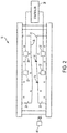
- the method of forming the aluminum alloy airfoil includes the use of a die unit 10, as illustrated in Fig. 2 .
- the die unit 10 is configured as a die press.
- the die unit 10 includes a pair of die plates 20, at least one heating element 22, at least one thermocouple 24, and a controller 26 in communication with the at least one heating element 22 and the at least one thermocouple 24.
- the die plates 20 are movable between an open position and a closed position.
- At least one of the die plates 20 is provided with a die shape 30 to form an aluminum alloy material into a desired airfoil shape.
- the aluminum alloy material is a precipitation hardenable aluminum alloy.
- a titanium alloy, a steel alloy, a nickel alloy, or the like may be used.
- the die plates 20 include at least one positioning locator 32.
- the at least one positioning locator(s) 32 locate the aluminum alloy material relative to the die shape 30 when the aluminum alloy material is inserted between the die plates 20.
- the at least one positioning locator(s) 32 are configured as fingers or protrusions that extend from a surface of at least one of the die plates 20.
- the die plates 20 of the die unit 10 are designed to have different lengths such that the positioning locators 32 do not engage each other.
- the at least one heating element 22 is disposed within at least one of the pair of die plates 20.
- the at least one heating element 22 may be a resistive heating element or the like that is configured to heat at least one of the die plates 20 to a predetermined temperature.
- the predetermined temperature may be within the range of 700°F to 900°F (371°C to 428°C).
- the at least one thermocouple 24 is disposed within at least one of the pair of die plates 20. In at least one embodiment, the at least one thermocouple 24 is disposed proximate the at least one heating element 22.
- the at least one thermocouple 24 is configured to measure a temperature of at least one of the die plates 20.
- a forced air cooler 40 is provided.
- the forced air cooler 40 is disposed proximate the die unit 10 adjacent to at least one of the die plates 20.
- the forced air cooler 40 is configured to provide forced ambient air to cool at least one of the die plates 20 to a temperature less than the predetermined temperature, such as an ambient temperature that may be within the range of 65°F to 80°F (18°C to 27°C).
- At block 100 at least one of the die plates 20 is heated by the at least one heating element 22 to the predetermined temperature such that the die unit 10 is considered a heated die.
- the controller 26 commands that a current or voltage be provided to the at least one heating element 22 from a power source.
- the aluminum alloy material is placed onto the heated die.
- the aluminum alloy material is placed onto at least one of the die plates 20 relative to the at least one positioning locator(s) 32 that are disposed relative to the die shape 30.
- the die unit 10 is maintained in an open position such that each of the die plates 20 are spaced apart from each other, at block 104. In at least one embodiment, the die unit is closed such that a top die plate makes contact with the aluminum alloy material.
- the heated die heats or pre-heats the aluminum alloy material to a first temperature for a first predetermined period of time, for example approximately one minute, at block 106.
- the first temperature is measured by the at least one thermocouple 24 or another temperature measurement device disposed proximate the aluminum alloy material.
- the first temperature is a predetermined temperature greater than a warm forming temperature. Warm forming temperatures are generally within the range of 500°F to 525°F (260°C to 274°C). In at least one embodiment, the first temperature is a temperature proximate the predetermined temperature of the hot die.
- the heated die is closed such that the die plates 20 move from the open position towards the closed position.
- the heated die is closed at a predetermined rate after the aluminum alloy material achieves the first temperature until the die plates 20 are completely closed.
- the die plates 20 are closed to slowly creep form the aluminum alloy material at a predetermined rate such that the die plates 20 achieve the closed position after two and a half minutes.
- the heated die is closed to deform the aluminum alloy material.
- the predetermined rate is a constant speed, incremental movements, or progressive movements.
- the heated die is held in the closed position.
- the heated die is held in the closed position for a second predetermined period of time, for example three to ten minutes, at a first force to creep form the aluminum alloy material to conform to the die shape 30.
- the die shape 30 forms a part that is made of a formed aluminum alloy material.
- the heated die is opened such that the die plates 20 move from the closed position towards the open position.
- the controller 26 continues to provide current or voltage to the at least one heating element 22.
- the controller 26 ceases the provision of current or voltage from the power source to the at least one heating element 22 in response to a command to open the die unit 10.
- the controller 26 ceases the provision of current or voltage from power source to the at least one heating element 22 in response to the die unit 10 achieving or moving towards the open position.
- the part made of the formed aluminum alloy material is removed from the die unit 10.
- the part made of the formed aluminum alloy material is removed to be cooled at an ambient temperature.
- the part made of the formed aluminum alloy material is cooled to a temperature proximate the ambient air temperature.
- the die plates 20 of the heated die are cooled by ambient air to the ambient temperature.
- the heated die is cooled such that at least one of the die plates 20 achieves the ambient air temperature.
- the heated die may be cooled by forced air to the ambient air temperature by the forced air cooler 40.
- the part made of the formed aluminum metal material is placed onto a heat treat fixture.
- the heat treat fixture includes controlled contours.
- the controlled contours may have a shape substantially similar to the shape of the part made of the formed aluminum alloy material.
- the controlled contours maintain or adjust the shape of the part made of the formed aluminum alloy material.
- the heat treat fixture and the part made of the formed aluminum alloy material are heat treated.
- the heat treat fixture and the part made of the formed aluminum alloy material are placed into an oven.
- the oven is heated to a second temperature prior to placing the heat treat fixture and the part made of the formed aluminum alloy material into the oven.
- the second temperature may be greater than the first temperature.
- the second temperature is a predetermined aluminum alloy material solution temperature that is within the range of 870°F to 940°F (465°C to 504°C).
- the heat treat fixture and the part made of the formed aluminum alloy material are held in the oven for a predetermined period of time, for example three to ten minutes.
- the heat treat fixture and the part made of the formed aluminum alloy material are quenched at a predetermined immersion rate.
- the heat treat fixture and the part made of the formed aluminum alloy material are quenched in a water bath or a water and glycol mixture bath.
- the water and glycol mixture bath may include glycol up to and including 40% of the bath volume.
- the quenching of the part made of the formed aluminum alloy material within the water and glycol mixture bath reduces distortion of the part made of the formed aluminum alloy material.
- the part made of the formed aluminum alloy material is quenched until the part temperature becomes below 85 °F (29°C). In at least one embodiment, the part made of the formed aluminum alloy material is quenched for approximately one to two minutes.
- the part made of the formed aluminum alloy material may be chilled.
- the part made of the formed aluminum alloy material may be placed on ice or in a freezer to cool the part made of the formed aluminum alloy material to a third temperature.
- the third temperature is less than the first temperature.
- the part formed of the aluminum alloy material remains on ice or in a freezer at least until the die plates 20 of the die unit 10 achieve approximately the ambient temperature.
- the part made of the formed aluminum alloy material is placed back onto at least one of the die plates 20 of the die unit 10. At least one of the die plates 20 of the die unit 10 is at an ambient temperature such that the die unit 10 is considered an ambient temperature die.
- the part made of the formed aluminum alloy material is placed relative to the at least one positioning locator(s) 32 that are disposed relative to the die shape 30.
- the part made of the formed aluminum alloy material is placed in a separate die unit having die plates that are at an ambient temperature.
- the die plates of the separate die unit may be considered an ambient temperature die.
- the ambient temperature die is closed such that the die plates 20 move from the open position towards the closed position.
- the die plates 20 are closed at a predetermined rate at a second force until the die plates 20 are completely closed.
- the second force may be greater than the first force.
- the ambient temperature die is closed to cold work the part made of the formed aluminum alloy material.
- the predetermined rate is a constant speed, incremental movements, or progressive movements.
- the die plates 20 are held in the closed position for a third predetermined period of time. In at least one embodiment, the third predetermined time period is less than the second predetermined period of time.
- the ambient temperature die is opened such that die plates 20 move from the closed position towards the open position.
- the part made of the formed aluminum alloy material is removed from the ambient temperature die.
- the part made of the formed aluminum alloy material is placed in a fixture and the combination of the part made of the formed aluminum alloy material and the fixture are placed in an oven for aging.
- the part made of the formed aluminum alloy material is artificially aged in the oven for a fourth predetermined period of time at a fourth temperature.
- the artificial aging process may be a two-stage aging process where the part made of the formed aluminum alloy material is aged at a temperature within the range of 225°F to 325°F (107°C to 163°C) and is subsequently aged at a temperature within the range of 310°F to 320°F (154°C to 160°C).
- the part made of the formed aluminum alloy material is inspected.
- the part is inspected for conformity with dimensional tolerances.
- the implementation of the method of forming an aluminum alloy airfoil reduces twist or dimensional issues of the part made of the formed aluminum alloy material.
- the method of forming an aluminum alloy airfoil reduces the amount of scrap and reduces the likelihood of hand working to achieve dimensional conformance.
- the method of forming the aluminum alloy airfoil is also cheaper than present aluminum alloy airfoil manufacturing processes.
Landscapes
- Engineering & Computer Science (AREA)
- Chemical & Material Sciences (AREA)
- Mechanical Engineering (AREA)
- Materials Engineering (AREA)
- Metallurgy (AREA)
- Organic Chemistry (AREA)
- General Engineering & Computer Science (AREA)
- Physics & Mathematics (AREA)
- Thermal Sciences (AREA)
- Crystallography & Structural Chemistry (AREA)
- Life Sciences & Earth Sciences (AREA)
- Agronomy & Crop Science (AREA)
- Shaping Metal By Deep-Drawing, Or The Like (AREA)
- Turbine Rotor Nozzle Sealing (AREA)
- Forging (AREA)
Abstract
Description
- The present disclosure relates to a method of forming aluminum alloy airfoils.
- Gas turbine engines are commonly provided with formed airfoils. The formed airfoils are made of a thin material. The thin material presents challenges in forming the airfoil.
- According to an embodiment of the present disclosure, a method of forming an airfoil is provided. The method includes placing a material onto a die that is heated to a predetermined temperature to pre-heat the material to a first temperature, while the die is in an open position. The method further includes closing the die at a predetermined rate and holding the die in a closed position for a predetermined period of time at a first force. The method still further includes removing the part from the die, cooling the die, placing the part onto the die, and closing the die at a second force.
- In addition to one or more of the features described above, or as an alternative to any of the foregoing embodiments, the method further includes cooling the part at an ambient temperature and heat treating the part at a second temperature for a predetermined time.
- In addition to one or more of the features described above, or as an alternative to any of the foregoing embodiments, the method further includes quenching the part by immersing the part at a predetermined immersion rate; and cooling the part at a third temperature at least until the die achieves approximately ambient temperature wherein the third temperature is less than the first temperature.
- In addition to one or more of the features described above, or as an alternative to any of the foregoing embodiments, the method further includes removing the part from the die; and aging the part at a fourth temperature for another predetermined period of time, wherein the fourth temperature is less than the first temperature.
- In addition to one or more of the features described above, or as an alternative to any of the foregoing embodiments, the die is cooled by ambient air.
- In addition to one or more of the features described above, or as an alternative to any of the foregoing embodiments, the die is cooled by forced air.
- In addition to one or more of the features described above, or as an alternative to any of the foregoing embodiments, the die includes a plurality of positioning locators to locate the material relative to a shape of the die.
- In addition to one or more of the features described above, or as an alternative to any of the foregoing embodiments, the die includes controller in communication with at least one thermocouple and at least one heating element that heats the die to the first temperature.
- According to another embodiment of the present disclosure, a method of forming an aluminum alloy airfoil is provided. The method includes placing an aluminum alloy material onto a heated die having position locators configured to locate the aluminum alloy material relative to a die shape within the heated die. The heated die is maintained in an open position for the first predetermined period of time to heat the aluminum alloy material to a predetermined temperature. The method further includes closing the heated die at a predetermined rate after the aluminum alloy material achieves the predetermined temperature and holding the heated die in a closed position for a second predetermined period of time to form a part made of a formed aluminum alloy material.
- In addition to one or more of the features described above, or as an alternative to any of the foregoing embodiments, the heated die includes a controller in communication with at least one heating element and at least one thermocouple.
- In addition to one or more of the features described above, or as an alternative to any of the foregoing embodiments, the method further includes opening the heated die; and removing the part made of the formed aluminum alloy material to cool the part made of the formed aluminum alloy material to an ambient air temperature.
- In addition to one or more of the features described above, or as an alternative to any of the foregoing embodiments, the method further includes placing the part made of the formed aluminum alloy material onto a heat treat fixture having controlled contours configured to maintain a shape of the part made of the formed aluminum alloy material; and heating the heat treat fixture and the part made of the formed aluminum alloy material to an aluminum alloy material solution temperature and time.
- In addition to one or more of the features described above, or as an alternative to any of the foregoing embodiments, the method further includes quenching the part made of the formed aluminum alloy material by immersion at a predetermined immersion rate.
- In addition to one or more of the features described above, or as an alternative to any of the foregoing embodiments, the method further includes placing the part made of the formed aluminum alloy material onto an ambient temperature die having positioning locators to locate the part made of the formed aluminum alloy material relative to an ambient temperature die shape; closing the ambient temperature die; and opening the ambient temperature die.
- In addition to one or more of the features described above, or as an alternative to any of the foregoing embodiments, an ambient temperature die temperature is less than a heated die temperature.
- In addition to one or more of the features described above, or as an alternative to any of the foregoing embodiments, the method further includes aging the part made of the formed aluminum alloy material.
- The subject matter which is regarded as the present disclosure is particularly pointed out and distinctly claimed in the claims at the conclusion of the specification. The foregoing and other features, and advantages of the present disclosure are apparent from the following detailed description taken in conjunction with the accompanying drawings in which:
-
FIG. 1 is a flowchart illustrating a method of forming an aluminum alloy airfoil; and -
FIG. 2 is a view of a die configured to form an aluminum alloy airfoil. - Referring now to the Figures, where the present disclosure will be described with reference to specific embodiments, it is to be understood that the disclosed embodiments are merely illustrative of the present disclosure that may be embodied in various and alternative forms. Various elements of the disclosed embodiments may be combined or omitted to form further embodiments of the present disclosure. The figures are not necessarily to scale; some features may be exaggerated or minimized to show details of particular components. Therefore, specific structural and functional details disclosed herein are not to be interpreted as limiting, but merely as a representative basis for teaching one skilled in the art to variously employ the present disclosure.
- Gas turbine engines are commonly provided with airfoils. The airfoils are inserted into a hub and the airfoils extend radially outward from the hub. The airfoils are formed of metallic alloys, such as an aluminum alloy, having a thin material thickness. Traditional methods to form the airfoil from the aluminum alloy generally involve cold forming the material into the desired airfoil shape. The cold forming process sometimes requires additional hand work to produce the desired tolerances. The additional hand work may produce inconsistency in the final product and present repeatability challenges.
- Airfoils generally do not possess a flat surface, but instead include twisted surfaces or non-flat surfaces that are difficult to form. The formation of such surfaces using traditional forming methods presents residual stresses and dimensional challenges. Referring to
Fig. 1 a flowchart illustrating a method of forming an aluminum alloy airfoil to alleviate such residual stresses and dimensional challenges is shown. - The method of forming the aluminum alloy airfoil includes the use of a
die unit 10, as illustrated inFig. 2 . The dieunit 10 is configured as a die press. The dieunit 10 includes a pair of dieplates 20, at least oneheating element 22, at least onethermocouple 24, and acontroller 26 in communication with the at least oneheating element 22 and the at least onethermocouple 24. The dieplates 20 are movable between an open position and a closed position. At least one of the dieplates 20 is provided with adie shape 30 to form an aluminum alloy material into a desired airfoil shape. The aluminum alloy material is a precipitation hardenable aluminum alloy. In at least one embodiment, a titanium alloy, a steel alloy, a nickel alloy, or the like may be used. - The die
plates 20 include at least onepositioning locator 32. The at least one positioning locator(s) 32 locate the aluminum alloy material relative to thedie shape 30 when the aluminum alloy material is inserted between thedie plates 20. The at least one positioning locator(s) 32 are configured as fingers or protrusions that extend from a surface of at least one of thedie plates 20. The dieplates 20 of thedie unit 10 are designed to have different lengths such that thepositioning locators 32 do not engage each other. - The at least one
heating element 22 is disposed within at least one of the pair of dieplates 20. The at least oneheating element 22 may be a resistive heating element or the like that is configured to heat at least one of thedie plates 20 to a predetermined temperature. The predetermined temperature may be within the range of 700°F to 900°F (371°C to 428°C). The at least onethermocouple 24 is disposed within at least one of the pair of dieplates 20. In at least one embodiment, the at least onethermocouple 24 is disposed proximate the at least oneheating element 22. The at least onethermocouple 24 is configured to measure a temperature of at least one of thedie plates 20. - In at least one embodiment, a forced
air cooler 40 is provided. The forcedair cooler 40 is disposed proximate thedie unit 10 adjacent to at least one of thedie plates 20. The forcedair cooler 40 is configured to provide forced ambient air to cool at least one of thedie plates 20 to a temperature less than the predetermined temperature, such as an ambient temperature that may be within the range of 65°F to 80°F (18°C to 27°C). - Referring to
Fig. 1 , atblock 100, at least one of thedie plates 20 is heated by the at least oneheating element 22 to the predetermined temperature such that thedie unit 10 is considered a heated die. To heat at least one of thedie plates 20, thecontroller 26 commands that a current or voltage be provided to the at least oneheating element 22 from a power source. - At
block 102, the aluminum alloy material is placed onto the heated die. The aluminum alloy material is placed onto at least one of thedie plates 20 relative to the at least one positioning locator(s) 32 that are disposed relative to thedie shape 30. Thedie unit 10 is maintained in an open position such that each of thedie plates 20 are spaced apart from each other, atblock 104. In at least one embodiment, the die unit is closed such that a top die plate makes contact with the aluminum alloy material. - The heated die heats or pre-heats the aluminum alloy material to a first temperature for a first predetermined period of time, for example approximately one minute, at
block 106. The first temperature is measured by the at least onethermocouple 24 or another temperature measurement device disposed proximate the aluminum alloy material. The first temperature is a predetermined temperature greater than a warm forming temperature. Warm forming temperatures are generally within the range of 500°F to 525°F (260°C to 274°C). In at least one embodiment, the first temperature is a temperature proximate the predetermined temperature of the hot die. - At
block 108, the heated die is closed such that thedie plates 20 move from the open position towards the closed position. The heated die is closed at a predetermined rate after the aluminum alloy material achieves the first temperature until thedie plates 20 are completely closed. For example, thedie plates 20 are closed to slowly creep form the aluminum alloy material at a predetermined rate such that thedie plates 20 achieve the closed position after two and a half minutes. The heated die is closed to deform the aluminum alloy material. The predetermined rate is a constant speed, incremental movements, or progressive movements. - At
block 110, the heated die is held in the closed position. The heated die is held in the closed position for a second predetermined period of time, for example three to ten minutes, at a first force to creep form the aluminum alloy material to conform to thedie shape 30. Thedie shape 30 forms a part that is made of a formed aluminum alloy material. - At
block 112, the heated die is opened such that thedie plates 20 move from the closed position towards the open position. In at least one embodiment, thecontroller 26 continues to provide current or voltage to the at least oneheating element 22. In at least one embodiment, thecontroller 26 ceases the provision of current or voltage from the power source to the at least oneheating element 22 in response to a command to open thedie unit 10. In at least one embodiment, thecontroller 26 ceases the provision of current or voltage from power source to the at least oneheating element 22 in response to thedie unit 10 achieving or moving towards the open position. - At
block 114, the part made of the formed aluminum alloy material is removed from thedie unit 10. The part made of the formed aluminum alloy material is removed to be cooled at an ambient temperature. The part made of the formed aluminum alloy material is cooled to a temperature proximate the ambient air temperature. - At
block 116, thedie plates 20 of the heated die are cooled by ambient air to the ambient temperature. The heated die is cooled such that at least one of thedie plates 20 achieves the ambient air temperature. The heated die may be cooled by forced air to the ambient air temperature by the forcedair cooler 40. - At
block 118, the part made of the formed aluminum metal material is placed onto a heat treat fixture. The heat treat fixture includes controlled contours. The controlled contours may have a shape substantially similar to the shape of the part made of the formed aluminum alloy material. The controlled contours maintain or adjust the shape of the part made of the formed aluminum alloy material. - At
block 120, the heat treat fixture and the part made of the formed aluminum alloy material are heat treated. The heat treat fixture and the part made of the formed aluminum alloy material are placed into an oven. The oven is heated to a second temperature prior to placing the heat treat fixture and the part made of the formed aluminum alloy material into the oven. The second temperature may be greater than the first temperature. The second temperature is a predetermined aluminum alloy material solution temperature that is within the range of 870°F to 940°F (465°C to 504°C). The heat treat fixture and the part made of the formed aluminum alloy material are held in the oven for a predetermined period of time, for example three to ten minutes. - At
block 122, the heat treat fixture and the part made of the formed aluminum alloy material are quenched at a predetermined immersion rate. The heat treat fixture and the part made of the formed aluminum alloy material are quenched in a water bath or a water and glycol mixture bath. The water and glycol mixture bath may include glycol up to and including 40% of the bath volume. The quenching of the part made of the formed aluminum alloy material within the water and glycol mixture bath reduces distortion of the part made of the formed aluminum alloy material. The part made of the formed aluminum alloy material is quenched until the part temperature becomes below 85 °F (29°C). In at least one embodiment, the part made of the formed aluminum alloy material is quenched for approximately one to two minutes. - Subsequent to the quenching of the part made of the formed aluminum alloy material, the part made of the formed aluminum alloy material may be chilled. The part made of the formed aluminum alloy material may be placed on ice or in a freezer to cool the part made of the formed aluminum alloy material to a third temperature. The third temperature is less than the first temperature. In at least one embodiment, the part formed of the aluminum alloy material remains on ice or in a freezer at least until the
die plates 20 of thedie unit 10 achieve approximately the ambient temperature. - At
block 124, the part made of the formed aluminum alloy material is placed back onto at least one of thedie plates 20 of thedie unit 10. At least one of thedie plates 20 of thedie unit 10 is at an ambient temperature such that thedie unit 10 is considered an ambient temperature die. The part made of the formed aluminum alloy material is placed relative to the at least one positioning locator(s) 32 that are disposed relative to thedie shape 30. In at least one embodiment, the part made of the formed aluminum alloy material is placed in a separate die unit having die plates that are at an ambient temperature. The die plates of the separate die unit may be considered an ambient temperature die. - At
block 126, the ambient temperature die is closed such that thedie plates 20 move from the open position towards the closed position. Thedie plates 20 are closed at a predetermined rate at a second force until thedie plates 20 are completely closed. The second force may be greater than the first force. The ambient temperature die is closed to cold work the part made of the formed aluminum alloy material. The predetermined rate is a constant speed, incremental movements, or progressive movements. Thedie plates 20 are held in the closed position for a third predetermined period of time. In at least one embodiment, the third predetermined time period is less than the second predetermined period of time. - At
block 128, the ambient temperature die is opened such that dieplates 20 move from the closed position towards the open position. Atblock 130, the part made of the formed aluminum alloy material is removed from the ambient temperature die. - At
block 132, the part made of the formed aluminum alloy material is placed in a fixture and the combination of the part made of the formed aluminum alloy material and the fixture are placed in an oven for aging. The part made of the formed aluminum alloy material is artificially aged in the oven for a fourth predetermined period of time at a fourth temperature. The artificial aging process may be a two-stage aging process where the part made of the formed aluminum alloy material is aged at a temperature within the range of 225°F to 325°F (107°C to 163°C) and is subsequently aged at a temperature within the range of 310°F to 320°F (154°C to 160°C). - At
block 134, the part made of the formed aluminum alloy material is inspected. The part is inspected for conformity with dimensional tolerances. - The implementation of the method of forming an aluminum alloy airfoil reduces twist or dimensional issues of the part made of the formed aluminum alloy material. The method of forming an aluminum alloy airfoil reduces the amount of scrap and reduces the likelihood of hand working to achieve dimensional conformance. The method of forming the aluminum alloy airfoil is also cheaper than present aluminum alloy airfoil manufacturing processes.
- While the present disclosure has been described in detail in connection with only a limited number of embodiments, it should be readily understood that the present disclosure is not limited to such disclosed embodiments. Rather, the present disclosure can be modified to incorporate any number of variations, alterations, substitutions or equivalent arrangements not heretofore described, but which are commensurate with the scope of the present disclosure. Additionally, while various embodiments of the present disclosure have been described, it is to be understood that aspects of the present disclosure may include only some of the described embodiments. Accordingly, the present disclosure is not to be seen as limited by the foregoing description, but is only limited by the scope of the appended claims.
Claims (15)
- A method of forming an airfoil, comprising:placing (102) a material onto a die (10) that is heated (100) to a predetermined temperature to pre-heat (106) the material to a first temperature, while the die is in an open position (104);closing (108) the die at a predetermined rate;holding (110) the die in a closed position for a predetermined period of time at a first force;removing (114) the part from the die;cooling (116) the die;placing (124) the part onto the die; andclosing (126) the die at a second force.
- The method of claim 1, further comprising:cooling the part at an ambient temperature; andheat treating (120) the part at a second temperature for a predetermined time.
- The method of claim 2, wherein the second temperature is greater than the first temperature.
- The method of claim 2 or 3, further comprising:quenching (122) the part by immersing the part at a predetermined immersion rate; andcooling the part at a third temperature at least until the die achieves approximately ambient temperature wherein the third temperature is less than the first temperature.
- The method of claim 4, further comprising:removing (130) the part from the die; andaging (132) the part at a fourth temperature for another predetermined period of time, wherein the fourth temperature is less than the first temperature.
- The method of any preceding claim, wherein the die includes a plurality of positioning locators (32) to locate the material relative to a shape (30) of the die.
- The method of any preceding claim, wherein the die includes a controller (26) in communication with at least one thermocouple (24) and at least one heating element (22) that heats the die to the first temperature.
- A method of forming an aluminum alloy airfoil, comprising:placing (102) an aluminum alloy material onto a heated die (10) having position locators (32) configured to locate the aluminum alloy material relative to a die shape (30) within the heated die;maintaining (104) the heated die in an open position for a first predetermined period of time to heat (106) the aluminum alloy material to a predetermined temperature;closing (108) the heated die at predetermined rate after the aluminum alloy material achieves the predetermined temperature; andholding (110) the heated die in a closed position for a second predetermined period of time to form a part made of a formed aluminum alloy material.
- The method of claim 8, wherein the heated die includes a controller (26) in communication with at least one heating element (22) and at least one thermocouple (24).
- The method of claim 8 or 9, further comprising:opening (112) the heated die; andremoving (114) the part made of the formed aluminum alloy material to cool the part made of the formed aluminum alloy material to an ambient air temperature.
- The method of claim 8, 9 or 10, further comprising:placing (118) the part made of the formed aluminum alloy material onto a heat treat fixture having controlled contours configured to maintain a shape of the part made of the formed aluminum alloy material; andheating (120) the heat treat fixture and the part made of the formed aluminum alloy material to an aluminum alloy material solution temperature and time.
- The method of any of claims 8 to 11, further comprising:quenching (122) the part made of the formed aluminum alloy material by immersion at a predetermined immersion rate.
- The method of any of claims 8 to 12, further comprising:placing (124) the part made of the formed aluminum alloy material onto an ambient temperature die having positioning locators (32) to locate the part made of the formed aluminum alloy material relative to an ambient temperature die shape;closing (126) the ambient temperature die; andopening (128) the ambient temperature die.
- The method of claim 13, wherein an ambient temperature die temperature is less than a heated die temperature.
- The method of any of claims 8 to 14, further comprising:aging (132) the part made of the formed aluminum alloy material.
Applications Claiming Priority (1)
| Application Number | Priority Date | Filing Date | Title |
|---|---|---|---|
| US15/075,795 US10704127B2 (en) | 2016-03-21 | 2016-03-21 | Method of forming aluminum alloy airfoils |
Publications (3)
| Publication Number | Publication Date |
|---|---|
| EP3225713A2 true EP3225713A2 (en) | 2017-10-04 |
| EP3225713A3 EP3225713A3 (en) | 2017-12-27 |
| EP3225713B1 EP3225713B1 (en) | 2019-08-21 |
Family
ID=58464168
Family Applications (1)
| Application Number | Title | Priority Date | Filing Date |
|---|---|---|---|
| EP17162173.3A Active EP3225713B1 (en) | 2016-03-21 | 2017-03-21 | Method of forming aluminum alloy airfoils |
Country Status (2)
| Country | Link |
|---|---|
| US (1) | US10704127B2 (en) |
| EP (1) | EP3225713B1 (en) |
Families Citing this family (1)
| Publication number | Priority date | Publication date | Assignee | Title |
|---|---|---|---|---|
| US11759837B1 (en) * | 2018-10-24 | 2023-09-19 | Abl Space Systems | Systems and methods for launch vehicle dome manufacturing |
Family Cites Families (10)
| Publication number | Priority date | Publication date | Assignee | Title |
|---|---|---|---|---|
| US4048836A (en) * | 1972-09-28 | 1977-09-20 | Wyman-Gordon Company | Forming and heat treating process |
| US4616499A (en) * | 1985-10-17 | 1986-10-14 | Lockheed Corporation | Isothermal forging method |
| US5108519A (en) * | 1988-01-28 | 1992-04-28 | Aluminum Company Of America | Aluminum-lithium alloys suitable for forgings |
| US6786272B2 (en) * | 2000-11-30 | 2004-09-07 | Copper Development Association, Inc. | Apparatus and method for die casting |
| GB0817169D0 (en) * | 2008-09-19 | 2008-10-29 | Univ Birmingham | Improved process for forming aluminium alloy sheet components |
| GB2473298B (en) * | 2009-11-13 | 2011-07-13 | Imp Innovations Ltd | A method of forming a component of complex shape from aluminium alloy sheet |
| US9233414B2 (en) | 2012-01-31 | 2016-01-12 | United Technologies Corporation | Aluminum airfoil |
| US8845945B2 (en) | 2012-02-29 | 2014-09-30 | United Technologies Corporation | Method of securing low density filler in cavities of a blade body of a fan blade |
| US20160108505A1 (en) * | 2013-07-04 | 2016-04-21 | Showa Denko K.K. | Method for producing starting material for cutting |
| CN108500184A (en) | 2013-07-10 | 2018-09-07 | 奥科宁克有限公司 | Method for making forging product and other converted products |
-
2016
- 2016-03-21 US US15/075,795 patent/US10704127B2/en active Active
-
2017
- 2017-03-21 EP EP17162173.3A patent/EP3225713B1/en active Active
Non-Patent Citations (1)
| Title |
|---|
| None |
Also Published As
| Publication number | Publication date |
|---|---|
| US20170268087A1 (en) | 2017-09-21 |
| EP3225713B1 (en) | 2019-08-21 |
| EP3225713A3 (en) | 2017-12-27 |
| US10704127B2 (en) | 2020-07-07 |
Similar Documents
| Publication | Publication Date | Title |
|---|---|---|
| AU2019261124A1 (en) | Hot-stamping forming method for lightweight aluminum alloy vehicle body component | |
| CN106170577B (en) | Method for forming parts from sheet metal alloys | |
| CN103128267B (en) | Shape the method for F- tempering aluminium alloys | |
| US10501829B2 (en) | Method for producing a structural sheet metal component, and a structural sheet metal component | |
| CN104962847B (en) | A Heat Treatment Process for Improving the Uniformity and Corrosion Resistance of 7 Series Alloy Thick Plates | |
| CN103341586B (en) | Method for achieving forming of GH4738 nickel-base superalloy turbine discs | |
| CN102896267B (en) | Isothermal forging method of TC17 titanium alloy disc-shaped forge piece | |
| CN104551561A (en) | Nut processing technology | |
| KR102098271B1 (en) | Hot press forming method of Al alloy sheet | |
| JP2012510565A (en) | Processing for forming aluminum alloy sheet parts | |
| CN109706297B (en) | Heat treatment method of H13 die steel | |
| KR20180004278A (en) | New 6xxx aluminum alloy and its manufacturing method | |
| CN103934642B (en) | A kind of steel cold-extrusion technology | |
| CN111315910A (en) | Method and system for shaping aluminum alloy blanks | |
| MX2019011941A (en) | Steel member, hot-rolled steel sheet for said steel member and production methods therefor. | |
| CN110434275B (en) | A kind of forging method of GH4586 superalloy | |
| CN101906518B (en) | Post-forging heat treatment process for nickeliferous dilute alloy round steel | |
| EP3225713B1 (en) | Method of forming aluminum alloy airfoils | |
| Vrolijk et al. | Supporting lightweight design: virtual modeling of hot stamping with tailored properties and warm and hot formed aluminium | |
| CN110983005B (en) | Heat treatment method of 0Cr11Ni2MoVNb steel forging | |
| CN104561869B (en) | A kind of titanium alloy profile stretch wrap forming situ heat treatment method | |
| CN115740321B (en) | Method for determining die forging parameters of titanium alloy with basket-like structure having broken grain boundaries | |
| WO2016067045A1 (en) | Material and process for preparing and forming an aluminium alloy material | |
| CN111485071A (en) | Quenching, tempering and straightening method for asymmetric structure clamp body in machining center | |
| CN107755446A (en) | A kind of processing technology of raising DT4C pure iron magnetic behaviors |
Legal Events
| Date | Code | Title | Description |
|---|---|---|---|
| PUAI | Public reference made under article 153(3) epc to a published international application that has entered the european phase |
Free format text: ORIGINAL CODE: 0009012 |
|
| STAA | Information on the status of an ep patent application or granted ep patent |
Free format text: STATUS: THE APPLICATION HAS BEEN PUBLISHED |
|
| AK | Designated contracting states |
Kind code of ref document: A2 Designated state(s): AL AT BE BG CH CY CZ DE DK EE ES FI FR GB GR HR HU IE IS IT LI LT LU LV MC MK MT NL NO PL PT RO RS SE SI SK SM TR |
|
| AX | Request for extension of the european patent |
Extension state: BA ME |
|
| REG | Reference to a national code |
Ref country code: DE Ref legal event code: R079 Ref document number: 602017006239 Country of ref document: DE Free format text: PREVIOUS MAIN CLASS: C22F0001040000 Ipc: C22C0021000000 |
|
| PUAL | Search report despatched |
Free format text: ORIGINAL CODE: 0009013 |
|
| AK | Designated contracting states |
Kind code of ref document: A3 Designated state(s): AL AT BE BG CH CY CZ DE DK EE ES FI FR GB GR HR HU IE IS IT LI LT LU LV MC MK MT NL NO PL PT RO RS SE SI SK SM TR |
|
| AX | Request for extension of the european patent |
Extension state: BA ME |
|
| RIC1 | Information provided on ipc code assigned before grant |
Ipc: C22C 21/00 20060101AFI20171121BHEP Ipc: C22F 1/04 20060101ALI20171121BHEP Ipc: F01D 5/28 20060101ALI20171121BHEP |
|
| STAA | Information on the status of an ep patent application or granted ep patent |
Free format text: STATUS: REQUEST FOR EXAMINATION WAS MADE |
|
| 17P | Request for examination filed |
Effective date: 20180627 |
|
| RBV | Designated contracting states (corrected) |
Designated state(s): AL AT BE BG CH CY CZ DE DK EE ES FI FR GB GR HR HU IE IS IT LI LT LU LV MC MK MT NL NO PL PT RO RS SE SI SK SM TR |
|
| GRAP | Despatch of communication of intention to grant a patent |
Free format text: ORIGINAL CODE: EPIDOSNIGR1 |
|
| STAA | Information on the status of an ep patent application or granted ep patent |
Free format text: STATUS: GRANT OF PATENT IS INTENDED |
|
| INTG | Intention to grant announced |
Effective date: 20190227 |
|
| GRAS | Grant fee paid |
Free format text: ORIGINAL CODE: EPIDOSNIGR3 |
|
| GRAA | (expected) grant |
Free format text: ORIGINAL CODE: 0009210 |
|
| STAA | Information on the status of an ep patent application or granted ep patent |
Free format text: STATUS: THE PATENT HAS BEEN GRANTED |
|
| AK | Designated contracting states |
Kind code of ref document: B1 Designated state(s): AL AT BE BG CH CY CZ DE DK EE ES FI FR GB GR HR HU IE IS IT LI LT LU LV MC MK MT NL NO PL PT RO RS SE SI SK SM TR |
|
| REG | Reference to a national code |
Ref country code: GB Ref legal event code: FG4D |
|
| REG | Reference to a national code |
Ref country code: CH Ref legal event code: EP |
|
| REG | Reference to a national code |
Ref country code: DE Ref legal event code: R096 Ref document number: 602017006239 Country of ref document: DE |
|
| REG | Reference to a national code |
Ref country code: AT Ref legal event code: REF Ref document number: 1169838 Country of ref document: AT Kind code of ref document: T Effective date: 20190915 |
|
| REG | Reference to a national code |
Ref country code: IE Ref legal event code: FG4D |
|
| REG | Reference to a national code |
Ref country code: LT Ref legal event code: MG4D |
|
| REG | Reference to a national code |
Ref country code: NL Ref legal event code: MP Effective date: 20190821 |
|
| PG25 | Lapsed in a contracting state [announced via postgrant information from national office to epo] |
Ref country code: SE Free format text: LAPSE BECAUSE OF FAILURE TO SUBMIT A TRANSLATION OF THE DESCRIPTION OR TO PAY THE FEE WITHIN THE PRESCRIBED TIME-LIMIT Effective date: 20190821 Ref country code: BG Free format text: LAPSE BECAUSE OF FAILURE TO SUBMIT A TRANSLATION OF THE DESCRIPTION OR TO PAY THE FEE WITHIN THE PRESCRIBED TIME-LIMIT Effective date: 20191121 Ref country code: LT Free format text: LAPSE BECAUSE OF FAILURE TO SUBMIT A TRANSLATION OF THE DESCRIPTION OR TO PAY THE FEE WITHIN THE PRESCRIBED TIME-LIMIT Effective date: 20190821 Ref country code: NL Free format text: LAPSE BECAUSE OF FAILURE TO SUBMIT A TRANSLATION OF THE DESCRIPTION OR TO PAY THE FEE WITHIN THE PRESCRIBED TIME-LIMIT Effective date: 20190821 Ref country code: HR Free format text: LAPSE BECAUSE OF FAILURE TO SUBMIT A TRANSLATION OF THE DESCRIPTION OR TO PAY THE FEE WITHIN THE PRESCRIBED TIME-LIMIT Effective date: 20190821 Ref country code: PT Free format text: LAPSE BECAUSE OF FAILURE TO SUBMIT A TRANSLATION OF THE DESCRIPTION OR TO PAY THE FEE WITHIN THE PRESCRIBED TIME-LIMIT Effective date: 20191223 Ref country code: FI Free format text: LAPSE BECAUSE OF FAILURE TO SUBMIT A TRANSLATION OF THE DESCRIPTION OR TO PAY THE FEE WITHIN THE PRESCRIBED TIME-LIMIT Effective date: 20190821 Ref country code: NO Free format text: LAPSE BECAUSE OF FAILURE TO SUBMIT A TRANSLATION OF THE DESCRIPTION OR TO PAY THE FEE WITHIN THE PRESCRIBED TIME-LIMIT Effective date: 20191121 |
|
| PG25 | Lapsed in a contracting state [announced via postgrant information from national office to epo] |
Ref country code: LV Free format text: LAPSE BECAUSE OF FAILURE TO SUBMIT A TRANSLATION OF THE DESCRIPTION OR TO PAY THE FEE WITHIN THE PRESCRIBED TIME-LIMIT Effective date: 20190821 Ref country code: ES Free format text: LAPSE BECAUSE OF FAILURE TO SUBMIT A TRANSLATION OF THE DESCRIPTION OR TO PAY THE FEE WITHIN THE PRESCRIBED TIME-LIMIT Effective date: 20190821 Ref country code: AL Free format text: LAPSE BECAUSE OF FAILURE TO SUBMIT A TRANSLATION OF THE DESCRIPTION OR TO PAY THE FEE WITHIN THE PRESCRIBED TIME-LIMIT Effective date: 20190821 Ref country code: IS Free format text: LAPSE BECAUSE OF FAILURE TO SUBMIT A TRANSLATION OF THE DESCRIPTION OR TO PAY THE FEE WITHIN THE PRESCRIBED TIME-LIMIT Effective date: 20191221 Ref country code: GR Free format text: LAPSE BECAUSE OF FAILURE TO SUBMIT A TRANSLATION OF THE DESCRIPTION OR TO PAY THE FEE WITHIN THE PRESCRIBED TIME-LIMIT Effective date: 20191122 Ref country code: RS Free format text: LAPSE BECAUSE OF FAILURE TO SUBMIT A TRANSLATION OF THE DESCRIPTION OR TO PAY THE FEE WITHIN THE PRESCRIBED TIME-LIMIT Effective date: 20190821 |
|
| REG | Reference to a national code |
Ref country code: AT Ref legal event code: MK05 Ref document number: 1169838 Country of ref document: AT Kind code of ref document: T Effective date: 20190821 |
|
| PG25 | Lapsed in a contracting state [announced via postgrant information from national office to epo] |
Ref country code: TR Free format text: LAPSE BECAUSE OF FAILURE TO SUBMIT A TRANSLATION OF THE DESCRIPTION OR TO PAY THE FEE WITHIN THE PRESCRIBED TIME-LIMIT Effective date: 20190821 |
|
| PG25 | Lapsed in a contracting state [announced via postgrant information from national office to epo] |
Ref country code: AT Free format text: LAPSE BECAUSE OF FAILURE TO SUBMIT A TRANSLATION OF THE DESCRIPTION OR TO PAY THE FEE WITHIN THE PRESCRIBED TIME-LIMIT Effective date: 20190821 Ref country code: RO Free format text: LAPSE BECAUSE OF FAILURE TO SUBMIT A TRANSLATION OF THE DESCRIPTION OR TO PAY THE FEE WITHIN THE PRESCRIBED TIME-LIMIT Effective date: 20190821 Ref country code: EE Free format text: LAPSE BECAUSE OF FAILURE TO SUBMIT A TRANSLATION OF THE DESCRIPTION OR TO PAY THE FEE WITHIN THE PRESCRIBED TIME-LIMIT Effective date: 20190821 Ref country code: PL Free format text: LAPSE BECAUSE OF FAILURE TO SUBMIT A TRANSLATION OF THE DESCRIPTION OR TO PAY THE FEE WITHIN THE PRESCRIBED TIME-LIMIT Effective date: 20190821 Ref country code: IT Free format text: LAPSE BECAUSE OF FAILURE TO SUBMIT A TRANSLATION OF THE DESCRIPTION OR TO PAY THE FEE WITHIN THE PRESCRIBED TIME-LIMIT Effective date: 20190821 Ref country code: DK Free format text: LAPSE BECAUSE OF FAILURE TO SUBMIT A TRANSLATION OF THE DESCRIPTION OR TO PAY THE FEE WITHIN THE PRESCRIBED TIME-LIMIT Effective date: 20190821 |
|
| PG25 | Lapsed in a contracting state [announced via postgrant information from national office to epo] |
Ref country code: IS Free format text: LAPSE BECAUSE OF FAILURE TO SUBMIT A TRANSLATION OF THE DESCRIPTION OR TO PAY THE FEE WITHIN THE PRESCRIBED TIME-LIMIT Effective date: 20200224 Ref country code: SM Free format text: LAPSE BECAUSE OF FAILURE TO SUBMIT A TRANSLATION OF THE DESCRIPTION OR TO PAY THE FEE WITHIN THE PRESCRIBED TIME-LIMIT Effective date: 20190821 Ref country code: CZ Free format text: LAPSE BECAUSE OF FAILURE TO SUBMIT A TRANSLATION OF THE DESCRIPTION OR TO PAY THE FEE WITHIN THE PRESCRIBED TIME-LIMIT Effective date: 20190821 Ref country code: SK Free format text: LAPSE BECAUSE OF FAILURE TO SUBMIT A TRANSLATION OF THE DESCRIPTION OR TO PAY THE FEE WITHIN THE PRESCRIBED TIME-LIMIT Effective date: 20190821 |
|
| REG | Reference to a national code |
Ref country code: DE Ref legal event code: R097 Ref document number: 602017006239 Country of ref document: DE |
|
| PLBE | No opposition filed within time limit |
Free format text: ORIGINAL CODE: 0009261 |
|
| STAA | Information on the status of an ep patent application or granted ep patent |
Free format text: STATUS: NO OPPOSITION FILED WITHIN TIME LIMIT |
|
| PG2D | Information on lapse in contracting state deleted |
Ref country code: IS |
|
| 26N | No opposition filed |
Effective date: 20200603 |
|
| PG25 | Lapsed in a contracting state [announced via postgrant information from national office to epo] |
Ref country code: SI Free format text: LAPSE BECAUSE OF FAILURE TO SUBMIT A TRANSLATION OF THE DESCRIPTION OR TO PAY THE FEE WITHIN THE PRESCRIBED TIME-LIMIT Effective date: 20190821 |
|
| PG25 | Lapsed in a contracting state [announced via postgrant information from national office to epo] |
Ref country code: MC Free format text: LAPSE BECAUSE OF FAILURE TO SUBMIT A TRANSLATION OF THE DESCRIPTION OR TO PAY THE FEE WITHIN THE PRESCRIBED TIME-LIMIT Effective date: 20190821 |
|
| REG | Reference to a national code |
Ref country code: CH Ref legal event code: PL |
|
| REG | Reference to a national code |
Ref country code: BE Ref legal event code: MM Effective date: 20200331 |
|
| PG25 | Lapsed in a contracting state [announced via postgrant information from national office to epo] |
Ref country code: LU Free format text: LAPSE BECAUSE OF NON-PAYMENT OF DUE FEES Effective date: 20200321 |
|
| PG25 | Lapsed in a contracting state [announced via postgrant information from national office to epo] |
Ref country code: IE Free format text: LAPSE BECAUSE OF NON-PAYMENT OF DUE FEES Effective date: 20200321 Ref country code: LI Free format text: LAPSE BECAUSE OF NON-PAYMENT OF DUE FEES Effective date: 20200331 Ref country code: CH Free format text: LAPSE BECAUSE OF NON-PAYMENT OF DUE FEES Effective date: 20200331 |
|
| PG25 | Lapsed in a contracting state [announced via postgrant information from national office to epo] |
Ref country code: BE Free format text: LAPSE BECAUSE OF NON-PAYMENT OF DUE FEES Effective date: 20200331 |
|
| PG25 | Lapsed in a contracting state [announced via postgrant information from national office to epo] |
Ref country code: MT Free format text: LAPSE BECAUSE OF FAILURE TO SUBMIT A TRANSLATION OF THE DESCRIPTION OR TO PAY THE FEE WITHIN THE PRESCRIBED TIME-LIMIT Effective date: 20190821 Ref country code: CY Free format text: LAPSE BECAUSE OF FAILURE TO SUBMIT A TRANSLATION OF THE DESCRIPTION OR TO PAY THE FEE WITHIN THE PRESCRIBED TIME-LIMIT Effective date: 20190821 |
|
| PG25 | Lapsed in a contracting state [announced via postgrant information from national office to epo] |
Ref country code: MK Free format text: LAPSE BECAUSE OF FAILURE TO SUBMIT A TRANSLATION OF THE DESCRIPTION OR TO PAY THE FEE WITHIN THE PRESCRIBED TIME-LIMIT Effective date: 20190821 |
|
| REG | Reference to a national code |
Ref country code: DE Ref legal event code: R081 Ref document number: 602017006239 Country of ref document: DE Owner name: RAYTHEON TECHNOLOGIES CORPORATION (N.D.GES.D.S, US Free format text: FORMER OWNER: UNITED TECHNOLOGIES CORPORATION, FARMINGTON, CONN., US Ref country code: DE Ref legal event code: R081 Ref document number: 602017006239 Country of ref document: DE Owner name: RTX CORPORATION (N.D.GES.D. STAATES DELAWARE),, US Free format text: FORMER OWNER: UNITED TECHNOLOGIES CORPORATION, FARMINGTON, CONN., US |
|
| P01 | Opt-out of the competence of the unified patent court (upc) registered |
Effective date: 20230520 |
|
| REG | Reference to a national code |
Ref country code: DE Ref legal event code: R081 Ref document number: 602017006239 Country of ref document: DE Owner name: RTX CORPORATION (N.D.GES.D. STAATES DELAWARE),, US Free format text: FORMER OWNER: RAYTHEON TECHNOLOGIES CORPORATION (N.D.GES.D.STAATES DELAWARE), ARLINGTON, VA, US |
|
| PGFP | Annual fee paid to national office [announced via postgrant information from national office to epo] |
Ref country code: GB Payment date: 20260220 Year of fee payment: 10 |
|
| PGFP | Annual fee paid to national office [announced via postgrant information from national office to epo] |
Ref country code: DE Payment date: 20260219 Year of fee payment: 10 |
|
| PGFP | Annual fee paid to national office [announced via postgrant information from national office to epo] |
Ref country code: FR Payment date: 20260220 Year of fee payment: 10 |