EP3225519B1 - Electrically controllable seat post - Google Patents
Electrically controllable seat post Download PDFInfo
- Publication number
- EP3225519B1 EP3225519B1 EP17164431.3A EP17164431A EP3225519B1 EP 3225519 B1 EP3225519 B1 EP 3225519B1 EP 17164431 A EP17164431 A EP 17164431A EP 3225519 B1 EP3225519 B1 EP 3225519B1
- Authority
- EP
- European Patent Office
- Prior art keywords
- pushing member
- seat post
- switch
- electromagnetic coil
- cylinder
- Prior art date
- Legal status (The legal status is an assumption and is not a legal conclusion. Google has not performed a legal analysis and makes no representation as to the accuracy of the status listed.)
- Active
Links
Images







Classifications
-
- B—PERFORMING OPERATIONS; TRANSPORTING
- B62—LAND VEHICLES FOR TRAVELLING OTHERWISE THAN ON RAILS
- B62J—CYCLE SADDLES OR SEATS; AUXILIARY DEVICES OR ACCESSORIES SPECIALLY ADAPTED TO CYCLES AND NOT OTHERWISE PROVIDED FOR, e.g. ARTICLE CARRIERS OR CYCLE PROTECTORS
- B62J1/00—Saddles or other seats for cycles; Arrangement thereof; Component parts
- B62J1/08—Frames for saddles; Connections between saddle frames and seat pillars; Seat pillars
-
- F—MECHANICAL ENGINEERING; LIGHTING; HEATING; WEAPONS; BLASTING
- F15—FLUID-PRESSURE ACTUATORS; HYDRAULICS OR PNEUMATICS IN GENERAL
- F15B—SYSTEMS ACTING BY MEANS OF FLUIDS IN GENERAL; FLUID-PRESSURE ACTUATORS, e.g. SERVOMOTORS; DETAILS OF FLUID-PRESSURE SYSTEMS, NOT OTHERWISE PROVIDED FOR
- F15B15/00—Fluid-actuated devices for displacing a member from one position to another; Gearing associated therewith
- F15B15/20—Other details, e.g. assembly with regulating devices
- F15B15/202—Externally-operated valves mounted in or on the actuator
-
- B—PERFORMING OPERATIONS; TRANSPORTING
- B62—LAND VEHICLES FOR TRAVELLING OTHERWISE THAN ON RAILS
- B62J—CYCLE SADDLES OR SEATS; AUXILIARY DEVICES OR ACCESSORIES SPECIALLY ADAPTED TO CYCLES AND NOT OTHERWISE PROVIDED FOR, e.g. ARTICLE CARRIERS OR CYCLE PROTECTORS
- B62J1/00—Saddles or other seats for cycles; Arrangement thereof; Component parts
- B62J1/08—Frames for saddles; Connections between saddle frames and seat pillars; Seat pillars
- B62J2001/085—Seat pillars having mechanisms to vary seat height, independently of the cycle frame
Definitions
- the present disclosure relates to a retractable seat post. More particularly, the present disclosure relates to an electrically controllable and retractable seat post that has higher retracting speed and stroke.
- a seat post that with a height-adjustable rod has been reached in the market.
- the height of this kind of retractable seat post can be manually controlled to adapt to variant road conditions.
- the saddle can be lowered by adjusting the height of the retractable seat post while riding downhill. Therefore, the center of gravity can be lowered so that the handling can be enhanced and the foot can touch the ground to assist to turn around the corner.
- This kind of retractable seat post is suitable for mountain biking or hillwood road biking owing to its capability of overcoming uncertainties of a rough road.
- a kind of retractable seat post is wire-controlled.
- An exposed wire is connected to the handle bar and the retractable seat post under the saddle, and a lever or other linkage mechanism is used to open a hydraulic or a pneumatic valve thereby elongating or contracting the retractable seat post.
- a lever or other linkage mechanism is used to open a hydraulic or a pneumatic valve thereby elongating or contracting the retractable seat post.
- U height adjustable seat posts comprising an electric motor by means of which a switch can be actuated.
- Patent specification US 8308124 B2 discloses a seat post allowing for a height adjustment of a saddle by means of a wire mechanism by which a switch can be actuated.
- the present invention provides an electrically controllable seat post having the features of claim 1. Further embodiments are subject-matter of the dependent claims.
- the electrically controllable seat post includes a retractable rod and a switch actuator.
- the retractable rod includes a switch and a cylinder, wherein the switch is configured to trigger an elongation and a contraction of the cylinder.
- the switch actuator is corresponding to the switch and includes a pushing member, an electromagnetic coil and a controller.
- the pushing member is linearly movable to open or close the switch so as to drive an elongation and a contraction of the retractable rod via elongation and contraction of the cylinder.
- the electromagnetic coil generates a magnetic force by injecting a current therethrough, wherein the pushing member has a pole of a magnetic field formed at an end of the pushing member by injecting the current through the electromagnetic coil or by a magnetic property at the end of the pushing member.
- the pushing member is directly and non-contactly driven by another pole of a magnetic field formed by the electromagnetic coil to be moved linearly.
- the controller controls the switch actuator.
- the electromagnetic coil includes an inner surface, the inner surface includes a spiral groove, the pushing member includes a protruding member corresponding to the spiral groove, and when the pushing member is elongated or contracted, the protruding member slides in the spiral groove to rotate the pushing member synchronously, so that the pushing member is linearly movable and rotatable to open or close the switch.
- the cylinder is a pneumatic cylinder, a hydraulic cylinder or a liquid-gas modularized cylinder, and the switch is located on the cylinder.
- the retractable rod is a pneumatic rod, a hydraulic rod or a liquid-gas modularized rod.
- the switch is a valve and the pushing member is moved to open or close the valve.
- the switch is a button and the pushing member is moved to push the button.
- the retractable rod includes a rod axis, and a moving direction of the pushing member is perpendicular to the rod axis.
- the switch actuator is immediately adjacent to the retractable rod.
- the electromagnetic coil is located in the retractable rod.
- the electromagnetic coil is located at an end of the retractable rod.
- the electrically controllable seat post includes a recovering member, wherein the recovering member is located between the electromagnetic coil and the pushing member for providing a recovering force.
- the pushing member includes at least one protruded limiting lever, an angle limitation mechanism is assembled outside of the limiting lever, the angle limitation mechanism opens at least one curved opening, the limiting lever is position-limitedly swung in the curved opening, and a rotation angle of the pushing member is constrained by the corporation between the limiting lever and the curved opening.
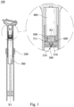
- Fig. 1 is a cross-sectional view of an electrically controllable seat post according to a first embodiment of the present disclosure
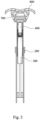
- Fig. 2 is a lateral cross-sectional view of a saddle of the electrically controllable seat post of Fig. 1
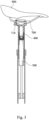
- Fig. 3 is a longitudinal cross-sectional view of the saddle of the electrically controllable seat post of Fig. 2 .
- an electrically controllable seat post 100 includes a retractable rod 200, a cylinder 300, an electromagnetic coil 400, a pushing member 500, a recovering member 600 and a controller 700.
- the electromagnetic coil 400 and the pushing member 500 are operated corporately as a switch actuator (unnumbered).
- the cylinder 300 is fixedly covered in the retractable rod 200.
- the cylinder 300 includes a switch 310 and a rod axis X1.
- a saddle 800 is assembled on the retractable rod 200.
- the switch 310 is used to trigger the elongation and contraction of the cylinder 300, and the elongation and contraction of the cylinder 300 drives the elongation and contraction of the retractable rod 200, thereby raising or lowering the saddle 800 instantly.
- the cylinder 300 can be a pneumatic cylinder, a hydraulic cylinder or a liquid-gas modularized cylinder; similarly, the retractable rod 200 can be a pneumatic rod, a hydraulic rod or a liquid-gas modularized rod. In the embodiment, the cylinder 300 is located inside of the retractable rod 200.
- the electromagnetic coil 400 is assembled in the retractable rod 200 and is corresponding to the switch 310.
- a portion of the pushing member 500 is assembled in the electromagnetic coil 400.
- a central axis X2 of the pushing member 500 is parallel to the rod axis X1 of the cylinder 300.
- One end 510 of the pushing member 500 is linearly moved by the electromagnetic coil 400 to open or close the switch 310.
- the recovering member 600 is made from an elastic material.
- the recovering member 600 provides a recovering force to the end 510 of the pushing member 500 so that the pushing member 500 is recovered to its original position.
- the controller 700 is assembled under the saddle 800.
- the controller 700 controls the electromagnetic coil 400 through a connecting wire 710.
- the central axis X2 of the pushing member 500 is parallel to the rod axis X1; therefore the switch 310 is triggered by the pushing member 500, which is linear activated by the electromagnetic coil 400.
- the controller 700 can control the electromagnetic coil 400 to trigger the switch 310 instantly.
- the recovering member 600 is used to provide the recovering force to the end 510 of the pushing member 500 to recover the pushing member 500 to its original position.
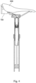
- Fig. 5 is a cross-sectional view of a saddle of an electrically controllable seat post according to a third embodiment of the present disclosure
- Fig. 6 is a cross-sectional view of a saddle of an electrically controllable seat post according to a fourth embodiment of the present disclosure.
- the end 510 is indirectly driven to trigger the switch 310, and the electromagnetic coil 400 is located outside of the retractable rod 200 and is assembled immediately adjacent to the retractable rod 200 to ensure that the central axis X2 is parallel to the rod axis X1.
- an inverted-U shaped hydraulic linkage mechanism 910 is located between the end 510 and the switch 310 for triggering the switch 310.
- the hydraulic linkage mechanism 910 includes components such as oil route, piston and oil injection channel, etc., and there is no description herein.
- a swing linkage mechanism 920 is located between the end 510 and the switch 310 for triggering the switch 310.
- the swing linkage mechanism 920 includes components such as a swing lever and a triggering lever, etc., and there is on description herein.
- Fig. 7 is a cross-sectional view of a saddle of an electrically controllable seat post according to a fifth embodiment of the present disclosure
- Fig. 8 is a cross-sectional view of a saddle of an electrically controllable seat post according to a sixth embodiment of the present disclosure.
- the central axis X2 and the rod axis X1 are coaxial, the end 510 is indirectly driven to trigger the switch 310, and the electromagnetic coil 400 is located inside of the retractable rod 200.
- the electromagnetic coil 400 is assembled at an upper end of the retractable rod 200 coaxially (upper end of the cylinder 300).
- an L-shaped linkage mechanism 930 is used to trigger the switch 310.
- the linkage mechanism 930 includes components such as an L-shaped lever and a vertical triggering lever, etc., and there is on description herein.
- the end 510 and the switch 310 are not necessarily located in the same axis owing to the L-shaped linkage mechanism 930.
- a close-type linkage mechanism 940 is located between the end 510 and the switch 310 for triggering the switch 310.
- the linkage mechanism 940 includes components such as double-inclined lever and a triggering lever, etc., and there is on description herein.
- Fig. 9 is a cross-sectional view of a saddle of an electrically controllable seat post according to a seventh embodiment of the present disclosure.
- the central axis X2 and the rod axis X1 are coaxial, the end 510 is indirectly driven to trigger the switch 310, and the electromagnetic coil 400 is located inside of the retractable rod 200.
- the electromagnetic coil 400 is assembled at an upper end of the cylinder 300.
- a vertical-type hydraulic linkage mechanism 950 is located between the end 510 and the switch 310 to trigger the switch 310.
- the vertical-type hydraulic linkage mechanism 950 includes components such as a vertical oil route and a piston, etc., and there is on description herein.
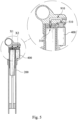
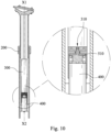
- Fig. 10 is a cross-sectional view of a saddle of an electrically controllable seat post according to an eighth embodiment of the present disclosure
- Fig. 11 is a longitudinal cross-sectional view of the saddle of the electrically controllable seat post of Fig. 10 .
- the central axis X2 and the rod axis X1 are coaxial, the end 510 is indirectly driven to trigger the switch 310, and the electromagnetic coil 400 is located inside of the retractable rod 200.
- the electromagnetic coil 400 is assembled at a bottom end of the cylinder 300.
- the controller 700 (and/or an electric controlling unit such as a battery and a chip, etc.) assembled in the retractable rod 200 can also be used to reduce the amount of components located under the saddle 800.
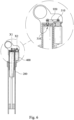
- Fig. 12 is a cross-sectional view of a saddle of an electrically controllable seat post according to a ninth embodiment of the present disclosure.
- the controller 700 (and/or an electric controlling unit such as a battery and a chip, etc.) is assembled outside of the retractable rod 200.
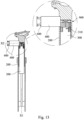
- Fig. 13 is a cross-sectional view of an electrically controllable seat post according to a tenth embodiment of the present disclosure.
- the electrically controllable seat post also includes the retractable rod 200, the electromagnetic coil 400 and the cylinder 300.
- the central axis X2 and the rod axis X1 are vertically arranged, and an L-shaped hydraulic linkage mechanism 960 is corporate with the switch 310 to raise or lower the saddle.
- the linkage mechanism 960 includes components such as double oil routes and piston, etc., and there is no description herein.
- the recovering member 600 is located outside of the electromagnetic coil 400 to provide a recovering force.
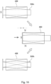
- Fig. 14 is a schematic view showing that a pushing member is rotated to open a switch 310 according to an eleventh embodiment of the present disclosure
- Fig. 15 is a schematic view showing that the pushing member is rotated to open the switch 310 of Fig. 14 .
- the pushing member 500 can be linearly moved as in the aforementioned embodiments; or a pushing member 500a can be rotated as in the eleventh embodiment of Fig. 14 .
- the rotation of the pushing member 500a is formed by the corporation of a spiral groove 401a formed in an inner surface of the electromagnetic coil 400a with a protruding member 501a (a steel ball).
- a protruding member 501a a steel ball.
- Fig. 16 shows an operation procedure of an electromagnetic coil and two pushing members
- Fig. 17 shows another operation procedure of the electromagnetic coil and the two pushing members of Fig. 16 .
- the pushing member can have a magnetic property.
- a pushing member 500c having a magnetic property at its end (functioned as an S pole in a magnetic field) and a pushing member 500b having no magnetic property are shown.
- the electromagnetic coil 400 and the pushing member 500b both have no magnetic field before injecting a current.
- the pushing member 500b or the pushing member 500c is linearly moved owing to the repulsion of the magnetic field.
- Fig. 18 a schematic view of an angle limitation mechanism of a pushing member according to a twelfth embodiment of the present disclosure.
- an angle limitation mechanism 970 is assembled in the pushing member 500a.
- the pushing member 500a further includes two L-shaped limiting levers 502a.
- the two limiting levers 502a are assembled diagonally, and a front end of each of the limiting levers 502a is protruded.
- the angle limitation mechanism 970 can be assembled at one end of the electromagnetic coil 400.
- the angle limitation mechanism 970 opens two curved openings 971, the front end of each of the limiting levers 502a is position-limitedly swung in the curved openings 971, and a rotation angle ⁇ of the pushing member 500a is constrained, thereby precisely controlling a movement of the pushing member 500a within the range of the rotation angle ⁇ .
- the present disclosure provides an electrically controllable seat post that using the switch actuator to activate a elongation and contraction of the retractable rod, and has advantages on wireless and precision control, rapid operation and minimizing cable routing.
Landscapes
- Engineering & Computer Science (AREA)
- Mechanical Engineering (AREA)
- Physics & Mathematics (AREA)
- Fluid Mechanics (AREA)
- General Engineering & Computer Science (AREA)
- Seats For Vehicles (AREA)
- Actuator (AREA)
- Lock And Its Accessories (AREA)
- Fluid-Damping Devices (AREA)
Description
- The present disclosure relates to a retractable seat post. More particularly, the present disclosure relates to an electrically controllable and retractable seat post that has higher retracting speed and stroke.
- Owing to the increasing demands of the bike riders, a seat post that with a height-adjustable rod (saddle) has been reached in the market. Conventionally, the height of this kind of retractable seat post can be manually controlled to adapt to variant road conditions. For example, the saddle can be lowered by adjusting the height of the retractable seat post while riding downhill. Therefore, the center of gravity can be lowered so that the handling can be enhanced and the foot can touch the ground to assist to turn around the corner. This kind of retractable seat post is suitable for mountain biking or hillwood road biking owing to its capability of overcoming uncertainties of a rough road.
- A kind of retractable seat post is wire-controlled. An exposed wire is connected to the handle bar and the retractable seat post under the saddle, and a lever or other linkage mechanism is used to open a hydraulic or a pneumatic valve thereby elongating or contracting the retractable seat post. However, no matter the wire is exposed out or not, interference or friction of the wire will commonly occur.
- Another kind of retractable seat post with electricity controllability has been developed. In this kind of seat post, a motor is used to activate a hydraulic valve or a pneumatic valve. In this kind of seat post, issues on wire interference or friction can be eliminated; however, other issues are raised. For example, a sufficient torque is required to open the hydraulic valve or the pneumatic valve, and since a rotation speed is inversely proportional to a torque in a motor, the response time of the motor to produce sufficient torque is too low to reflect the road condition immediately. Furthermore, an extra device (e.g. a gear box) is also required to be assembled with the motor, thus bringing the inconvenience on assembling. In other word, this kind of motor-driven seat post can eliminate wire interference or friction issue of the wire-controlled seat post, but will raise new issues on low response speed and inconvenience of assembling.
- Therefore, there is a need to develop a novel seat post that has low response time and is easy to assemble.
- From patent application publication
EP 2865586 A1 , which discloses all the features of the preamble of independent claim 1, and utility model publicationCN 204587107 U height adjustable seat posts are known comprising an electric motor by means of which a switch can be actuated. Patent specificationUS 8308124 B2 discloses a seat post allowing for a height adjustment of a saddle by means of a wire mechanism by which a switch can be actuated. - The present invention provides an electrically controllable seat post having the features of claim 1. Further embodiments are subject-matter of the dependent claims. The electrically controllable seat post includes a retractable rod and a switch actuator. The retractable rod includes a switch and a cylinder, wherein the switch is configured to trigger an elongation and a contraction of the cylinder. The switch actuator is corresponding to the switch and includes a pushing member, an electromagnetic coil and a controller. The pushing member is linearly movable to open or close the switch so as to drive an elongation and a contraction of the retractable rod via elongation and contraction of the cylinder. The electromagnetic coil generates a magnetic force by injecting a current therethrough, wherein the pushing member has a pole of a magnetic field formed at an end of the pushing member by injecting the current through the electromagnetic coil or by a magnetic property at the end of the pushing member. The pushing member is directly and non-contactly driven by another pole of a magnetic field formed by the electromagnetic coil to be moved linearly. The controller controls the switch actuator. The electromagnetic coil includes an inner surface, the inner surface includes a spiral groove, the pushing member includes a protruding member corresponding to the spiral groove, and when the pushing member is elongated or contracted, the protruding member slides in the spiral groove to rotate the pushing member synchronously, so that the pushing member is linearly movable and rotatable to open or close the switch.
- In one example, the cylinder is a pneumatic cylinder, a hydraulic cylinder or a liquid-gas modularized cylinder, and the switch is located on the cylinder.
- In one example, the retractable rod is a pneumatic rod, a hydraulic rod or a liquid-gas modularized rod.
- In one example, the switch is a valve and the pushing member is moved to open or close the valve.
- In one example, the switch is a button and the pushing member is moved to push the button.
- In one example, the retractable rod includes a rod axis, and a moving direction of the pushing member is perpendicular to the rod axis.
- In one example, the switch actuator is immediately adjacent to the retractable rod.
- In one example, the electromagnetic coil is located in the retractable rod.
- In one example, the electromagnetic coil is located at an end of the retractable rod.
- In one example, the electrically controllable seat post includes a recovering member, wherein the recovering member is located between the electromagnetic coil and the pushing member for providing a recovering force.
- In one example, the pushing member includes at least one protruded limiting lever, an angle limitation mechanism is assembled outside of the limiting lever, the angle limitation mechanism opens at least one curved opening, the limiting lever is position-limitedly swung in the curved opening, and a rotation angle of the pushing member is constrained by the corporation between the limiting lever and the curved opening.
- The present disclosure can be more fully understood by reading the following detailed description of the embodiment, with reference made to the accompanying drawings as follows:
-
Fig. 1 is a cross-sectional view of an electrically controllable seat post according to a first embodiment of the present disclosure; -
Fig. 2 is a lateral cross-sectional view of a saddle of the electrically controllable seat post ofFig. 1 ; -
Fig. 3 is a longitudinal cross-sectional view of the saddle of the electrically controllable seat post ofFig. 2 ; -
Fig. 4 is a cross-sectional view of a saddle of an electrically controllable seat post according to a second embodiment of the present disclosure; -
Fig. 5 is a cross-sectional view of a saddle of an electrically controllable seat post according to a third embodiment of the present disclosure; -
Fig. 6 is a cross-sectional view of a saddle of an electrically controllable seat post according to a fourth embodiment of the present disclosure; -
Fig. 7 is a cross-sectional view of a saddle of an electrically controllable seat post according to a fifth embodiment of the present disclosure; -
Fig. 8 is a cross-sectional view of a saddle of an electrically controllable seat post according to a sixth embodiment of the present disclosure; -
Fig. 9 is a cross-sectional view of a saddle of an electrically controllable seat post according to a seventh embodiment of the present disclosure; -
Fig. 10 is a cross-sectional view of a saddle of an electrically controllable seat post according to an eighth embodiment of the present disclosure; -
Figs. 11 is a longitudinal cross-sectional view of the saddle of the electrically controllable seat post ofFig. 10 ; -
Fig. 12 is a cross-sectional view of a saddle of an electrically controllable seat post according to a ninth embodiment of the present disclosure; -
Fig. 13 is a cross-sectional view of an electrically controllable seat post according to a tenth embodiment of the present disclosure; -
Fig. 14 is a schematic view showing that a pushing member is rotated to open a switch according to an eleventh embodiment of the present disclosure; -
Fig. 15 is a schematic view shows that the pushing member is rotated to open the switch ofFig. 14 ; -
Fig. 16 shows an operation procedure of an electromagnetic coil and two pushing members; -
Fig. 17 shows another operation procedure of the electromagnetic coil and the two pushing members ofFig. 16 ; and -
Fig. 18 a schematic view of an angle limitation mechanism of a pushing member according to a twelfth embodiment of the present disclosure. - It is a purpose of the present disclosure to provide an electrically controllable and retractable seat post that has no motor response delay and ease of assembling.
-
Fig. 1 is a cross-sectional view of an electrically controllable seat post according to a first embodiment of the present disclosure;Fig. 2 is a lateral cross-sectional view of a saddle of the electrically controllable seat post ofFig. 1 ;Fig. 3 is a longitudinal cross-sectional view of the saddle of the electrically controllable seat post ofFig. 2 . - In the first embodiment, an electrically
controllable seat post 100 includes aretractable rod 200, acylinder 300, anelectromagnetic coil 400, a pushingmember 500, a recoveringmember 600 and acontroller 700. Theelectromagnetic coil 400 and the pushingmember 500 are operated corporately as a switch actuator (unnumbered). - The
cylinder 300 is fixedly covered in theretractable rod 200. Thecylinder 300 includes aswitch 310 and a rod axis X1. Asaddle 800 is assembled on theretractable rod 200. Theswitch 310 is used to trigger the elongation and contraction of thecylinder 300, and the elongation and contraction of thecylinder 300 drives the elongation and contraction of theretractable rod 200, thereby raising or lowering thesaddle 800 instantly. Thecylinder 300 can be a pneumatic cylinder, a hydraulic cylinder or a liquid-gas modularized cylinder; similarly, theretractable rod 200 can be a pneumatic rod, a hydraulic rod or a liquid-gas modularized rod. In the embodiment, thecylinder 300 is located inside of theretractable rod 200. - The
electromagnetic coil 400 is assembled in theretractable rod 200 and is corresponding to theswitch 310. A portion of the pushingmember 500 is assembled in theelectromagnetic coil 400. A central axis X2 of the pushingmember 500 is parallel to the rod axis X1 of thecylinder 300. Oneend 510 of the pushingmember 500 is linearly moved by theelectromagnetic coil 400 to open or close theswitch 310. - The recovering
member 600 is made from an elastic material. The recoveringmember 600 provides a recovering force to theend 510 of the pushingmember 500 so that the pushingmember 500 is recovered to its original position. - The
controller 700 is assembled under thesaddle 800. Thecontroller 700 controls theelectromagnetic coil 400 through a connectingwire 710. - In the aforementioned first embodiment, the central axis X2 of the pushing
member 500 is parallel to the rod axis X1; therefore theswitch 310 is triggered by the pushingmember 500, which is linear activated by theelectromagnetic coil 400. Thecontroller 700 can control theelectromagnetic coil 400 to trigger theswitch 310 instantly. The recoveringmember 600 is used to provide the recovering force to theend 510 of the pushingmember 500 to recover the pushingmember 500 to its original position. -
Fig. 5 is a cross-sectional view of a saddle of an electrically controllable seat post according to a third embodiment of the present disclosure;Fig. 6 is a cross-sectional view of a saddle of an electrically controllable seat post according to a fourth embodiment of the present disclosure. - In the third embodiment and the fourth embodiment, the
end 510 is indirectly driven to trigger theswitch 310, and theelectromagnetic coil 400 is located outside of theretractable rod 200 and is assembled immediately adjacent to theretractable rod 200 to ensure that the central axis X2 is parallel to the rod axis X1. - In
Fig. 5 , an inverted-U shapedhydraulic linkage mechanism 910 is located between theend 510 and theswitch 310 for triggering theswitch 310. Conventionally, thehydraulic linkage mechanism 910 includes components such as oil route, piston and oil injection channel, etc., and there is no description herein. - In
Fig. 6 , aswing linkage mechanism 920 is located between theend 510 and theswitch 310 for triggering theswitch 310. Conventionally, theswing linkage mechanism 920 includes components such as a swing lever and a triggering lever, etc., and there is on description herein. -
Fig. 7 is a cross-sectional view of a saddle of an electrically controllable seat post according to a fifth embodiment of the present disclosure;Fig. 8 is a cross-sectional view of a saddle of an electrically controllable seat post according to a sixth embodiment of the present disclosure. - In the fifth embodiment and the sixth embodiment, the central axis X2 and the rod axis X1 are coaxial, the
end 510 is indirectly driven to trigger theswitch 310, and theelectromagnetic coil 400 is located inside of theretractable rod 200. Theelectromagnetic coil 400 is assembled at an upper end of theretractable rod 200 coaxially (upper end of the cylinder 300). - In
Fig. 7 , an L-shapedlinkage mechanism 930 is used to trigger theswitch 310. Conventionally, thelinkage mechanism 930 includes components such as an L-shaped lever and a vertical triggering lever, etc., and there is on description herein. InFig. 7 , theend 510 and theswitch 310 are not necessarily located in the same axis owing to the L-shapedlinkage mechanism 930. - In
Fig. 8 , a close-type linkage mechanism 940 is located between theend 510 and theswitch 310 for triggering theswitch 310. Conventionally, thelinkage mechanism 940 includes components such as double-inclined lever and a triggering lever, etc., and there is on description herein. -
Fig. 9 is a cross-sectional view of a saddle of an electrically controllable seat post according to a seventh embodiment of the present disclosure. - In the seventh embodiment, the central axis X2 and the rod axis X1 are coaxial, the
end 510 is indirectly driven to trigger theswitch 310, and theelectromagnetic coil 400 is located inside of theretractable rod 200. Theelectromagnetic coil 400 is assembled at an upper end of thecylinder 300. A vertical-typehydraulic linkage mechanism 950 is located between theend 510 and theswitch 310 to trigger theswitch 310. Conventionally, the vertical-typehydraulic linkage mechanism 950 includes components such as a vertical oil route and a piston, etc., and there is on description herein. -
Fig. 10 is a cross-sectional view of a saddle of an electrically controllable seat post according to an eighth embodiment of the present disclosure;Fig. 11 is a longitudinal cross-sectional view of the saddle of the electrically controllable seat post ofFig. 10 . - In the eighth embodiment, the central axis X2 and the rod axis X1 are coaxial, the
end 510 is indirectly driven to trigger theswitch 310, and theelectromagnetic coil 400 is located inside of theretractable rod 200. Theelectromagnetic coil 400 is assembled at a bottom end of thecylinder 300. The controller 700 (and/or an electric controlling unit such as a battery and a chip, etc.) assembled in theretractable rod 200 can also be used to reduce the amount of components located under thesaddle 800. -
Fig. 12 is a cross-sectional view of a saddle of an electrically controllable seat post according to a ninth embodiment of the present disclosure. - In
Fig. 12 , the controller 700 (and/or an electric controlling unit such as a battery and a chip, etc.) is assembled outside of theretractable rod 200. -
Fig. 13 is a cross-sectional view of an electrically controllable seat post according to a tenth embodiment of the present disclosure. - In
Fig. 13 , the electrically controllable seat post also includes theretractable rod 200, theelectromagnetic coil 400 and thecylinder 300. In the tenth embodiment ofFig. 13 , the central axis X2 and the rod axis X1 are vertically arranged, and an L-shapedhydraulic linkage mechanism 960 is corporate with theswitch 310 to raise or lower the saddle. Conventionally, thelinkage mechanism 960 includes components such as double oil routes and piston, etc., and there is no description herein. Furthermore, the recoveringmember 600 is located outside of theelectromagnetic coil 400 to provide a recovering force. -
Fig. 14 is a schematic view showing that a pushing member is rotated to open aswitch 310 according to an eleventh embodiment of the present disclosure;Fig. 15 is a schematic view showing that the pushing member is rotated to open theswitch 310 ofFig. 14 . - In the present disclosure, the pushing
member 500 can be linearly moved as in the aforementioned embodiments; or a pushingmember 500a can be rotated as in the eleventh embodiment ofFig. 14 . The rotation of the pushingmember 500a is formed by the corporation of aspiral groove 401a formed in an inner surface of theelectromagnetic coil 400a with a protrudingmember 501a (a steel ball). When an elongation and contraction of the pushingmember 500a is actuated by theelectromagnetic coil 400a, the protrudingmember 501a slides in thespiral groove 401a to rotate the pushingmember 500a. This kind of mechanism is to transfer a linear motion to a rotation motion and is a conventional technique. -
Fig. 16 shows an operation procedure of an electromagnetic coil and two pushing members;Fig. 17 shows another operation procedure of the electromagnetic coil and the two pushing members ofFig. 16 . - In one embodiment, the pushing member can have a magnetic property. In
Fig. 16 , a pushingmember 500c having a magnetic property at its end (functioned as an S pole in a magnetic field) and a pushingmember 500b having no magnetic property are shown. Theelectromagnetic coil 400 and the pushingmember 500b both have no magnetic field before injecting a current. When the current is injected to theelectromagnetic coil 400, a corresponding N pole in a magnetic field is formed, and the pushingmember 500b or the pushingmember 500c is linearly moved owing to the repulsion of the magnetic field. -
Fig. 18 a schematic view of an angle limitation mechanism of a pushing member according to a twelfth embodiment of the present disclosure. - In the twelfth embodiment of
Fig. 18 , anangle limitation mechanism 970 is assembled in the pushingmember 500a. The pushingmember 500a further includes two L-shaped limitinglevers 502a. The two limitinglevers 502a are assembled diagonally, and a front end of each of the limitinglevers 502a is protruded. Theangle limitation mechanism 970 can be assembled at one end of theelectromagnetic coil 400. Theangle limitation mechanism 970 opens twocurved openings 971, the front end of each of the limitinglevers 502a is position-limitedly swung in thecurved openings 971, and a rotation angle θ of the pushingmember 500a is constrained, thereby precisely controlling a movement of the pushingmember 500a within the range of the rotation angle θ. - In sum, the present disclosure provides an electrically controllable seat post that using the switch actuator to activate a elongation and contraction of the retractable rod, and has advantages on wireless and precision control, rapid operation and minimizing cable routing.
Claims (11)
- An electrically controllable seat post (100), comprising:a retractable rod (200) comprising a switch (310) and a cylinder (300), wherein the switch (310) is configured to trigger an elongation and a contraction of the cylinder (300); anda switch actuator corresponding to the switch (310) and comprising:a pushing member (500), which is linearly movable to open or close the switch (310) so as to drive an elongation and a contraction of the retractable rod (200) via elongation and contraction of the cylinder (300); andan electromagnetic coil (400) generating a magnetic force by injecting a current therethrough; anda controller (700) controlling the switch actuator;wherein the pushing member (500) has a pole of a magnetic field formed at an end of the pushing member (500) by injecting the current through the electromagnetic coil (400) or by a magnetic property at the end of the pushing member (500);wherein the pushing member (500) is directly and non-contactly driven by another pole of a magnetic field formed by the electromagnetic coil (400) to be moved linearly;characterised in thatthe electromagnetic coil (400) comprises an inner surface, the inner surface comprises a spiral groove (401a), the pushing member (500) comprises a protruding member (501a) corresponding to the spiral groove (401a), and when the pushing member (500) is elongated or contracted, the protruding member (501a) slides in the spiral groove (401a) to rotate the pushing member (500) synchronously, so that the pushing member (500) is linearly movable and rotatable to open or close the switch (310).
- The seat post (100) of claim 1, wherein the cylinder (300) is a pneumatic cylinder, a hydraulic cylinder or a liquid-gas modularized cylinder, and the switch (310) is located on the cylinder (300).
- The seat post (100) of claim 1, wherein the retractable rod (200) is a pneumatic rod, a hydraulic rod or a liquid-gas modularized rod.
- The seat post of claim 1, wherein the switch (310) is a valve and the pushing member (500) is moved to open or close the valve.
- The seat post (100) of claim 1, wherein the switch (310) is a button and the pushing member (500) is moved to push the button.
- The seat post (100) of claim 1, wherein the retractable rod (200) has a rod axis (X1), and a moving direction of the pushing member (500) is perpendicular to the rod axis (X1).
- The seat post (100) of claim 1, wherein the switch actuator is immediately adjacent to the retractable rod (200).
- The seat post (100) of claim 1, wherein the electromagnetic coil (400a) is located in the retractable rod (200).
- The seat post (100) of claim 1, wherein the electromagnetic coil (400) is located at an end of the retractable rod (200).
- The seat post (100) of claim 1, further comprising a recovering member (600), wherein the recovering member (600) is located between the electromagnetic coil (400) and the pushing member (500) for providing a recovering force.
- The seat post (100) of claim 1, wherein the pushing member (500a) comprises at least one protruded limiting lever (502a), an angle limitation mechanism (970) is assembled outside of the limiting lever (502a), the angle limitation mechanism (970) opens at least one curved opening (971), the limiting lever (502a) is position-limitedly swung in the curved opening (971), and a rotation angle ( θ ) of the pushing member (500a) is constrained by the corporation between the limiting lever (502a) and the curved opening (971).
Applications Claiming Priority (1)
| Application Number | Priority Date | Filing Date | Title |
|---|---|---|---|
| TW105204620U TWM525882U (en) | 2016-04-01 | 2016-04-01 | Electronically controlled telescopic seatpost structure |
Publications (4)
| Publication Number | Publication Date |
|---|---|
| EP3225519A2 EP3225519A2 (en) | 2017-10-04 |
| EP3225519A3 EP3225519A3 (en) | 2017-11-08 |
| EP3225519C0 EP3225519C0 (en) | 2024-11-06 |
| EP3225519B1 true EP3225519B1 (en) | 2024-11-06 |
Family
ID=56996614
Family Applications (1)
| Application Number | Title | Priority Date | Filing Date |
|---|---|---|---|
| EP17164431.3A Active EP3225519B1 (en) | 2016-04-01 | 2017-03-31 | Electrically controllable seat post |
Country Status (5)
| Country | Link |
|---|---|
| US (1) | US20170282986A1 (en) |
| EP (1) | EP3225519B1 (en) |
| AU (2) | AU2017202078A1 (en) |
| CA (1) | CA2962848C (en) |
| TW (1) | TWM525882U (en) |
Families Citing this family (10)
| Publication number | Priority date | Publication date | Assignee | Title |
|---|---|---|---|---|
| US10759483B2 (en) | 2015-10-01 | 2020-09-01 | Shimano Inc. | Bicycle and electrical seatpost assembly |
| TWI589475B (en) | 2016-08-31 | 2017-07-01 | 巨大機械工業股份有限公司 | Adjustable seat tube structure and bicycle thereof |
| US10843757B2 (en) * | 2017-03-08 | 2020-11-24 | Shimano Inc. | Bicycle electric telescopic apparatus, bicycle power supply system, and bicycle electric component system |
| US10363980B2 (en) * | 2017-06-20 | 2019-07-30 | Tien Hsin Industries Co., Ltd. | Bicycle controlling device |
| US11180212B2 (en) * | 2018-07-17 | 2021-11-23 | Shimano Inc. | Fluid flow control structure for a telescopic apparatus of a human powered vehicle |
| US11697467B2 (en) * | 2020-10-02 | 2023-07-11 | Shimano Inc. | Rider-posture changing device |
| US12269547B2 (en) | 2022-11-21 | 2025-04-08 | Sram, Llc | Seat post assembly with automatic power connector |
| US12291297B2 (en) | 2022-11-21 | 2025-05-06 | Sram, Llc | Height adjustable seat posts for bicycles |
| US12703448B2 (en) | 2023-09-25 | 2026-08-11 | Sram, Llc | Height adjustable seat posts for bicycles |
| TWI922876B (en) * | 2023-12-29 | 2026-04-21 | 久鼎金屬實業股份有限公司 | Adjustable lifting seat post with maximum lifting stroke |
Family Cites Families (6)
| Publication number | Priority date | Publication date | Assignee | Title |
|---|---|---|---|---|
| JPH02113506A (en) * | 1988-10-22 | 1990-04-25 | Matsushita Electric Works Ltd | Solenoid |
| DE4311625A1 (en) * | 1993-04-08 | 1994-10-13 | Stabilus Gmbh | Pneumatic, hydraulic or hydropneumatic adjusting device |
| DE102008047745B4 (en) * | 2008-09-17 | 2015-04-30 | Stabilus Gmbh | Height-adjustable furniture |
| US8308124B2 (en) * | 2010-10-28 | 2012-11-13 | Jung Yu Hsu | Control device for adjustable bicycle seat |
| CN203601454U (en) * | 2013-10-28 | 2014-05-21 | 久鼎金属实业股份有限公司 | Adjustable seat tube assembly of bicycle |
| CN204587107U (en) * | 2015-02-15 | 2015-08-26 | 久鼎金属实业股份有限公司 | Electronic inner and outer tube regulating mechanism for bicycle |
-
2016
- 2016-04-01 TW TW105204620U patent/TWM525882U/en not_active IP Right Cessation
-
2017
- 2017-03-29 CA CA2962848A patent/CA2962848C/en active Active
- 2017-03-29 AU AU2017202078A patent/AU2017202078A1/en not_active Abandoned
- 2017-03-29 US US15/472,305 patent/US20170282986A1/en not_active Abandoned
- 2017-03-31 EP EP17164431.3A patent/EP3225519B1/en active Active
-
2019
- 2019-04-17 AU AU2019202699A patent/AU2019202699B2/en active Active
Also Published As
| Publication number | Publication date |
|---|---|
| AU2017202078A1 (en) | 2017-10-19 |
| AU2019202699A1 (en) | 2019-05-16 |
| CA2962848A1 (en) | 2017-10-01 |
| TWM525882U (en) | 2016-07-21 |
| EP3225519A2 (en) | 2017-10-04 |
| AU2019202699B2 (en) | 2021-02-04 |
| EP3225519C0 (en) | 2024-11-06 |
| CA2962848C (en) | 2021-12-07 |
| US20170282986A1 (en) | 2017-10-05 |
| EP3225519A3 (en) | 2017-11-08 |
Similar Documents
| Publication | Publication Date | Title |
|---|---|---|
| AU2019202699B2 (en) | Electrically controllable seat post | |
| EP2886428B1 (en) | Seat tube assembly for bicycle | |
| JP6590468B2 (en) | Bicycle gearshift device controlled by improved precision control | |
| TWI770339B (en) | Bicycle telescopic apparatus | |
| CN103189271B (en) | Snowmobile suspension load regulating mechanism | |
| EP2402239A1 (en) | Adjustable seat post | |
| EP3746355A1 (en) | Device for adjusting a seat position of a bicycle seat | |
| EP3290311B1 (en) | Adjustable seat tube structure | |
| EP2977171A1 (en) | Bottle blowing machine | |
| CA2345560A1 (en) | Rotary steerable drilling tool | |
| CN215285077U (en) | Bicycle seat post structure | |
| JP5806947B2 (en) | Band saw device | |
| CN115094803B (en) | Municipal administration road rail guard | |
| US10864955B2 (en) | Telescopic seat post | |
| CN106494491B (en) | The big stroke pneumatic steering column of vehicle steering wheel | |
| CN202491039U (en) | Forklift portal support assembly-welding locating device | |
| JP5525372B2 (en) | Welding gun | |
| CN105178759A (en) | Mechanism for ascending and descending of car window | |
| EP1442819A3 (en) | Resistance welding machine for sheets | |
| CN105788918B (en) | A kind of assembling device of insulated tension pole | |
| CN106245707B (en) | Travelling control foot pedal assembly | |
| JP2013092015A (en) | Pile driver | |
| CN211231809U (en) | Passive point extreme position feedback mechanism | |
| US20220324686A1 (en) | Multi-dimensional adjustable forklift driving system | |
| CN203666322U (en) | Walking device suitable for various road conditions |
Legal Events
| Date | Code | Title | Description |
|---|---|---|---|
| PUAI | Public reference made under article 153(3) epc to a published international application that has entered the european phase |
Free format text: ORIGINAL CODE: 0009012 |
|
| STAA | Information on the status of an ep patent application or granted ep patent |
Free format text: STATUS: THE APPLICATION HAS BEEN PUBLISHED |
|
| AK | Designated contracting states |
Kind code of ref document: A2 Designated state(s): AL AT BE BG CH CY CZ DE DK EE ES FI FR GB GR HR HU IE IS IT LI LT LU LV MC MK MT NL NO PL PT RO RS SE SI SK SM TR |
|
| AX | Request for extension of the european patent |
Extension state: BA ME |
|
| PUAL | Search report despatched |
Free format text: ORIGINAL CODE: 0009013 |
|
| AK | Designated contracting states |
Kind code of ref document: A3 Designated state(s): AL AT BE BG CH CY CZ DE DK EE ES FI FR GB GR HR HU IE IS IT LI LT LU LV MC MK MT NL NO PL PT RO RS SE SI SK SM TR |
|
| AX | Request for extension of the european patent |
Extension state: BA ME |
|
| RIC1 | Information provided on ipc code assigned before grant |
Ipc: B62J 1/08 20060101AFI20171003BHEP |
|
| STAA | Information on the status of an ep patent application or granted ep patent |
Free format text: STATUS: REQUEST FOR EXAMINATION WAS MADE |
|
| 17P | Request for examination filed |
Effective date: 20180504 |
|
| RBV | Designated contracting states (corrected) |
Designated state(s): AL AT BE BG CH CY CZ DE DK EE ES FI FR GB GR HR HU IE IS IT LI LT LU LV MC MK MT NL NO PL PT RO RS SE SI SK SM TR |
|
| STAA | Information on the status of an ep patent application or granted ep patent |
Free format text: STATUS: EXAMINATION IS IN PROGRESS |
|
| 17Q | First examination report despatched |
Effective date: 20191204 |
|
| GRAP | Despatch of communication of intention to grant a patent |
Free format text: ORIGINAL CODE: EPIDOSNIGR1 |
|
| STAA | Information on the status of an ep patent application or granted ep patent |
Free format text: STATUS: GRANT OF PATENT IS INTENDED |
|
| INTG | Intention to grant announced |
Effective date: 20240212 |
|
| GRAS | Grant fee paid |
Free format text: ORIGINAL CODE: EPIDOSNIGR3 |
|
| GRAA | (expected) grant |
Free format text: ORIGINAL CODE: 0009210 |
|
| STAA | Information on the status of an ep patent application or granted ep patent |
Free format text: STATUS: THE PATENT HAS BEEN GRANTED |
|
| AK | Designated contracting states |
Kind code of ref document: B1 Designated state(s): AL AT BE BG CH CY CZ DE DK EE ES FI FR GB GR HR HU IE IS IT LI LT LU LV MC MK MT NL NO PL PT RO RS SE SI SK SM TR |
|
| REG | Reference to a national code |
Ref country code: GB Ref legal event code: FG4D |
|
| REG | Reference to a national code |
Ref country code: CH Ref legal event code: EP |
|
| REG | Reference to a national code |
Ref country code: DE Ref legal event code: R096 Ref document number: 602017085893 Country of ref document: DE |
|
| REG | Reference to a national code |
Ref country code: IE Ref legal event code: FG4D |
|
| U01 | Request for unitary effect filed |
Effective date: 20241127 |
|
| U07 | Unitary effect registered |
Designated state(s): AT BE BG DE DK EE FI FR IT LT LU LV MT NL PT RO SE SI Effective date: 20241204 |
|
| PG25 | Lapsed in a contracting state [announced via postgrant information from national office to epo] |
Ref country code: HR Free format text: LAPSE BECAUSE OF FAILURE TO SUBMIT A TRANSLATION OF THE DESCRIPTION OR TO PAY THE FEE WITHIN THE PRESCRIBED TIME-LIMIT Effective date: 20241106 Ref country code: IS Free format text: LAPSE BECAUSE OF FAILURE TO SUBMIT A TRANSLATION OF THE DESCRIPTION OR TO PAY THE FEE WITHIN THE PRESCRIBED TIME-LIMIT Effective date: 20250306 |
|
| PG25 | Lapsed in a contracting state [announced via postgrant information from national office to epo] |
Ref country code: ES Free format text: LAPSE BECAUSE OF FAILURE TO SUBMIT A TRANSLATION OF THE DESCRIPTION OR TO PAY THE FEE WITHIN THE PRESCRIBED TIME-LIMIT Effective date: 20241106 |
|
| PG25 | Lapsed in a contracting state [announced via postgrant information from national office to epo] |
Ref country code: NO Free format text: LAPSE BECAUSE OF FAILURE TO SUBMIT A TRANSLATION OF THE DESCRIPTION OR TO PAY THE FEE WITHIN THE PRESCRIBED TIME-LIMIT Effective date: 20250206 |
|
| PG25 | Lapsed in a contracting state [announced via postgrant information from national office to epo] |
Ref country code: GR Free format text: LAPSE BECAUSE OF FAILURE TO SUBMIT A TRANSLATION OF THE DESCRIPTION OR TO PAY THE FEE WITHIN THE PRESCRIBED TIME-LIMIT Effective date: 20250207 |
|
| PG25 | Lapsed in a contracting state [announced via postgrant information from national office to epo] |
Ref country code: PL Free format text: LAPSE BECAUSE OF FAILURE TO SUBMIT A TRANSLATION OF THE DESCRIPTION OR TO PAY THE FEE WITHIN THE PRESCRIBED TIME-LIMIT Effective date: 20241106 |
|
| PG25 | Lapsed in a contracting state [announced via postgrant information from national office to epo] |
Ref country code: RS Free format text: LAPSE BECAUSE OF FAILURE TO SUBMIT A TRANSLATION OF THE DESCRIPTION OR TO PAY THE FEE WITHIN THE PRESCRIBED TIME-LIMIT Effective date: 20250206 |
|
| U20 | Renewal fee for the european patent with unitary effect paid |
Year of fee payment: 9 Effective date: 20250327 |
|
| PG25 | Lapsed in a contracting state [announced via postgrant information from national office to epo] |
Ref country code: SM Free format text: LAPSE BECAUSE OF FAILURE TO SUBMIT A TRANSLATION OF THE DESCRIPTION OR TO PAY THE FEE WITHIN THE PRESCRIBED TIME-LIMIT Effective date: 20241106 |
|
| PG25 | Lapsed in a contracting state [announced via postgrant information from national office to epo] |
Ref country code: SK Free format text: LAPSE BECAUSE OF FAILURE TO SUBMIT A TRANSLATION OF THE DESCRIPTION OR TO PAY THE FEE WITHIN THE PRESCRIBED TIME-LIMIT Effective date: 20241106 |
|
| PG25 | Lapsed in a contracting state [announced via postgrant information from national office to epo] |
Ref country code: CZ Free format text: LAPSE BECAUSE OF FAILURE TO SUBMIT A TRANSLATION OF THE DESCRIPTION OR TO PAY THE FEE WITHIN THE PRESCRIBED TIME-LIMIT Effective date: 20241106 |
|
| PLBE | No opposition filed within time limit |
Free format text: ORIGINAL CODE: 0009261 |
|
| STAA | Information on the status of an ep patent application or granted ep patent |
Free format text: STATUS: NO OPPOSITION FILED WITHIN TIME LIMIT |
|
| PG25 | Lapsed in a contracting state [announced via postgrant information from national office to epo] |
Ref country code: MC Free format text: LAPSE BECAUSE OF FAILURE TO SUBMIT A TRANSLATION OF THE DESCRIPTION OR TO PAY THE FEE WITHIN THE PRESCRIBED TIME-LIMIT Effective date: 20241106 |
|
| 26N | No opposition filed |
Effective date: 20250807 |
|
| REG | Reference to a national code |
Ref country code: CH Ref legal event code: H13 Free format text: ST27 STATUS EVENT CODE: U-0-0-H10-H13 (AS PROVIDED BY THE NATIONAL OFFICE) Effective date: 20251024 |
|
| PG25 | Lapsed in a contracting state [announced via postgrant information from national office to epo] |
Ref country code: CH Free format text: LAPSE BECAUSE OF NON-PAYMENT OF DUE FEES Effective date: 20250331 |
|
| PG25 | Lapsed in a contracting state [announced via postgrant information from national office to epo] |
Ref country code: IE Free format text: LAPSE BECAUSE OF NON-PAYMENT OF DUE FEES Effective date: 20250331 |
|
| PGFP | Annual fee paid to national office [announced via postgrant information from national office to epo] |
Ref country code: GB Payment date: 20260323 Year of fee payment: 10 |
|
| U20 | Renewal fee for the european patent with unitary effect paid |
Year of fee payment: 10 Effective date: 20260324 |
|
| PG25 | Lapsed in a contracting state [announced via postgrant information from national office to epo] |
Ref country code: CY Free format text: LAPSE BECAUSE OF FAILURE TO SUBMIT A TRANSLATION OF THE DESCRIPTION OR TO PAY THE FEE WITHIN THE PRESCRIBED TIME-LIMIT Effective date: 20241106 |