EP3225295A1 - Oil catcher - Google Patents
Oil catcher Download PDFInfo
- Publication number
- EP3225295A1 EP3225295A1 EP15857689.2A EP15857689A EP3225295A1 EP 3225295 A1 EP3225295 A1 EP 3225295A1 EP 15857689 A EP15857689 A EP 15857689A EP 3225295 A1 EP3225295 A1 EP 3225295A1
- Authority
- EP
- European Patent Office
- Prior art keywords
- main
- filter unit
- unit
- oil
- main filter
- Prior art date
- Legal status (The legal status is an assumption and is not a legal conclusion. Google has not performed a legal analysis and makes no representation as to the accuracy of the status listed.)
- Granted
Links
- 239000012535 impurity Substances 0.000 claims abstract description 13
- 230000002093 peripheral effect Effects 0.000 claims description 9
- 239000000463 material Substances 0.000 claims description 8
- 238000004804 winding Methods 0.000 claims description 6
- 229920000728 polyester Polymers 0.000 claims description 5
- 230000008878 coupling Effects 0.000 description 5
- 238000010168 coupling process Methods 0.000 description 5
- 238000005859 coupling reaction Methods 0.000 description 5
- 230000000694 effects Effects 0.000 description 3
- 238000003780 insertion Methods 0.000 description 3
- 230000037431 insertion Effects 0.000 description 3
- 230000000149 penetrating effect Effects 0.000 description 3
- 238000003466 welding Methods 0.000 description 2
- 230000007613 environmental effect Effects 0.000 description 1
- 230000001050 lubricating effect Effects 0.000 description 1
- 238000012423 maintenance Methods 0.000 description 1
- 230000007257 malfunction Effects 0.000 description 1
- 238000004519 manufacturing process Methods 0.000 description 1
- 238000012986 modification Methods 0.000 description 1
- 230000004048 modification Effects 0.000 description 1
- 239000003921 oil Substances 0.000 description 1
- 238000004321 preservation Methods 0.000 description 1
- 239000007779 soft material Substances 0.000 description 1
- XLYOFNOQVPJJNP-UHFFFAOYSA-N water Substances O XLYOFNOQVPJJNP-UHFFFAOYSA-N 0.000 description 1
Images



Classifications
-
- B—PERFORMING OPERATIONS; TRANSPORTING
- B01—PHYSICAL OR CHEMICAL PROCESSES OR APPARATUS IN GENERAL
- B01D—SEPARATION
- B01D46/00—Filters or filtering processes specially modified for separating dispersed particles from gases or vapours
- B01D46/0027—Filters or filtering processes specially modified for separating dispersed particles from gases or vapours with additional separating or treating functions
- B01D46/003—Filters or filtering processes specially modified for separating dispersed particles from gases or vapours with additional separating or treating functions including coalescing means for the separation of liquid
- B01D46/0031—Filters or filtering processes specially modified for separating dispersed particles from gases or vapours with additional separating or treating functions including coalescing means for the separation of liquid with collecting, draining means
-
- B—PERFORMING OPERATIONS; TRANSPORTING
- B01—PHYSICAL OR CHEMICAL PROCESSES OR APPARATUS IN GENERAL
- B01D—SEPARATION
- B01D39/00—Filtering material for liquid or gaseous fluids
- B01D39/08—Filter cloth, i.e. woven, knitted or interlaced material
-
- B—PERFORMING OPERATIONS; TRANSPORTING
- B01—PHYSICAL OR CHEMICAL PROCESSES OR APPARATUS IN GENERAL
- B01D—SEPARATION
- B01D39/00—Filtering material for liquid or gaseous fluids
- B01D39/08—Filter cloth, i.e. woven, knitted or interlaced material
- B01D39/083—Filter cloth, i.e. woven, knitted or interlaced material of organic material
-
- B—PERFORMING OPERATIONS; TRANSPORTING
- B01—PHYSICAL OR CHEMICAL PROCESSES OR APPARATUS IN GENERAL
- B01D—SEPARATION
- B01D39/00—Filtering material for liquid or gaseous fluids
- B01D39/10—Filter screens essentially made of metal
- B01D39/12—Filter screens essentially made of metal of wire gauze; of knitted wire; of expanded metal
-
- B—PERFORMING OPERATIONS; TRANSPORTING
- B01—PHYSICAL OR CHEMICAL PROCESSES OR APPARATUS IN GENERAL
- B01D—SEPARATION
- B01D39/00—Filtering material for liquid or gaseous fluids
- B01D39/14—Other self-supporting filtering material ; Other filtering material
- B01D39/16—Other self-supporting filtering material ; Other filtering material of organic material, e.g. synthetic fibres
-
- B—PERFORMING OPERATIONS; TRANSPORTING
- B01—PHYSICAL OR CHEMICAL PROCESSES OR APPARATUS IN GENERAL
- B01D—SEPARATION
- B01D46/00—Filters or filtering processes specially modified for separating dispersed particles from gases or vapours
- B01D46/24—Particle separators, e.g. dust precipitators, using rigid hollow filter bodies
-
- F—MECHANICAL ENGINEERING; LIGHTING; HEATING; WEAPONS; BLASTING
- F04—POSITIVE - DISPLACEMENT MACHINES FOR LIQUIDS; PUMPS FOR LIQUIDS OR ELASTIC FLUIDS
- F04B—POSITIVE-DISPLACEMENT MACHINES FOR LIQUIDS; PUMPS
- F04B39/00—Component parts, details, or accessories, of pumps or pumping systems specially adapted for elastic fluids, not otherwise provided for in, or of interest apart from, groups F04B25/00 - F04B37/00
- F04B39/16—Filtration; Moisture separation
-
- B—PERFORMING OPERATIONS; TRANSPORTING
- B01—PHYSICAL OR CHEMICAL PROCESSES OR APPARATUS IN GENERAL
- B01D—SEPARATION
- B01D2239/00—Aspects relating to filtering material for liquid or gaseous fluids
- B01D2239/06—Filter cloth, e.g. knitted, woven non-woven; self-supported material
- B01D2239/069—Special geometry of layers
- B01D2239/0695—Wound layers
Definitions
- the present invention relates to a technical field relating to an oil catch apparatus disposed in piping for air passage and separating water, oil, impurities, and the like mixed in the air.
- the compressed air may contain oil for lubricating the inside of the compressor. If the oil enters the system, malfunction may occur.
- Patent Document 1 JP 2013-174224A
- the oil catch apparatus described in Patent Document 1 has a structure that separates the oil and recovers the same by making air containing the oil collide with a collision plate. Thus, it is necessary to ensure a distance for making the air collide with the collision plate, resulting in an increase in the apparatus size.
- the present invention has been made in view of the above situation, and an object thereof is to provide an oil catch apparatus capable of extracting a sufficient amount of oil albeit being of compact size.
- an oil catch apparatus includes: a main unit; a lid that covers the opening in the main unit; a hose that is attached to the lid; a filter that is located inside of the main unit; and a buffer that supports the filter.
- the filter includes a cylindrically wound main filter unit and a keep member that keeps both ends of the main filter unit. Air flowing into the main filter unit is cleared of impurities upon passing through the main filter unit, and then exits from a peripheral surface of the main filter unit.
- the main filter unit is formed by winding a network stainless material cylindrically and has inside a polyester mesh.
- the buffer includes a buffer member formed in such a way as to cover up a portion of the main filter unit on a side opposite to an air inflow side.
- the main unit includes an exhaust opening for an air exiting from the peripheral surface of the main filter unit for clearance of impurities
- the lid includes an inlet into which an air flows and a drain outlet out of which the impurities are drained.
- the oil catch apparatus further includes a cylindrical member that is attached to the lid.
- One side of the cylindrical member is coupled to the drain outlet and the other side of the cylindrical member is detachably mounted on a stop formed on the lid.
- an oil catch apparatus includes: a main unit; a lid that covers the opening in the main unit; a filter that is located inside of the main unit; and a buffer that supports the filter.
- the filter includes a cylindrically wound main filter unit and a keep member that keeps both ends of the main filter unit. Air flowing into the main filter unit is cleared of impurities upon passing through the main filter unit, and then exits from a peripheral surface of the main filter unit. Thus, the oil catch apparatus can extract a sufficient amount of oil albeit being of compact size.
- the main filter unit is formed by winding a network stainless material cylindrically and has inside a polyester mesh.
- a network stainless material cylindrically and has inside a polyester mesh.
- the buffer includes a buffer member formed in such a way as to cover up a portion of the main filter unit on a side opposite to an air inflow side.
- the main unit includes an exhaust opening for an air exiting from the peripheral surface of the main filter unit for clearance of impurities
- the lid includes an inlet into which an air flows and a drain outlet out of which the impurities are drained.
- the oil catch apparatus further includes a cylindrical member that is attached to the lid.
- One side of the cylindrical member is coupled to the drain outlet and the other side of the cylindrical member is detachably mounted on a stop formed on the lid.
- the tubular member is attached to the stop when not in use, while it can be easily removed from the stop when in use, making it possible to easily use the tubular member.
- FIG. 1 is a front view of an oil catch apparatus 1 according to an embodiment of the present invention.
- FIG. 2 is a side view of the oil catch apparatus 1 according to the present embodiment.
- FIG. 3 is a plan view of the oil catch apparatus 1 according to the present embodiment.
- the oil catch apparatus 1 includes a main unit 2, a lid 3 that covers the opening of the main unit 2, a hose 4 attached to the lid 3, an exhaust guide 5 that guides flow of exhaust air, and a mounting part 6 installed in the main unit 2.
- the main unit 2 has a cylinder 21, a bottom part 22, and a main unit flange 23.
- the cylinder 21 is formed into a cylindrical shape, it may have a rectangular cylindrical shape or an elliptic cylindrical shape.
- the bottom part 22 is formed so as to close one opening of the cylinder 21.
- An exhaust opening 22a is formed in the bottom part 22.
- the main unit flange 23 protrudes outward from the cylinder 21 at a side opposite to the bottom part 22 in a direction perpendicular to the longitudinal direction of the main unit 2.
- the cylinder 21, bottom part 22, and flange part 23 may be formed separately and joined together by welding or the like, they are preferably formed integrally.
- the lid 3 has a flat part 31, a side part 32, and a lid flange 33.
- the shape of the flat part 31 is preferably the same as that of the bottom part 22 of the main unit 2.
- An inlet 31a protrudes from the flat surface of the flat part 31 and has therein a hole penetrating therethrough in the same direction as the protruding direction thereof.
- the inlet 31a preferably protrudes in a direction perpendicular to the flat surface.
- the side part 32 extends in the vertical direction from the outer periphery of the flat part 31.
- the side part 32 has first and second protruding parts 32a and 32b protruding the side thereof.
- a drain outlet 31b protrudes from the flat surface of the side part 32 and has therein a hole penetrating therethrough in the same direction as the protruding direction thereof.
- a stop 31c protrudes from the flat surface of the second protruding part 32b.
- the first and second protruding parts 32a and 32b preferably protrude in a direction perpendicular to the side surface.
- the lid flange 33 protrudes outward from the side part 32 at a side opposite to the flat part 31 in a direction perpendicular to the longitudinal direction of the main unit 2.
- Coupling holes 23a and 33a through each of which a bolt B for coupling the main unit 2 and lid 3 penetrates are formed in the main unit flange 23 and lid flange 33, respectively.
- the bolt B penetrating through each of the coupling holes 23a and 33a is fastened by a nut N.
- the bolt B and nut N are used as a coupling part for coupling the main unit 2 and lid 3 in the present embodiment, another structure may be used.
- the hose 4 has a tubular member 41 made of a transparent or translucent soft material.
- One side of the tubular member 41 is coupled to the drain outlet 31b of the lid 3 by a first clip 42 or the like.
- the other side of the tubular member 41 is normally attached to the stop 31c by a second clip 43 or the like and is removed when oil or the like is discharged from the drain outlet 31b.
- the tubular member 41 is attached to the stop 31c by the second clip 43 when not in use, while it can be used by removing the second clip 43 when in use. That is, the tubular member 41 can be easily used in an attachable/detachable manner.
- the exhaust guide 5 is installed to the cylinder 21 so as to cover the exhaust opening 22a formed in the bottom part 22 of the main unit 2 with its eaves.
- the exhaust guide 5 guides exhaust gas exhausted from the exhaust opening 22a.
- the mounting part 6 is installed to the cylinder 21 of the main unit 2.
- the main unit 2 is mounted to a not illustrated vehicle body through the mounting part 6.
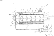
- FIG. 4 is a cross-sectional view of the oil catch apparatus 1 according to the present embodiment.
- the oil catch apparatus 1 has inside thereof a filter 7 and a buffer 8 supporting the filter 7.
- the filter 7 has a main filter unit 71, a first keep member 72, and a second keep member 73.
- the main filter unit 71 is formed by stacking a network stainless material and a polyester mesh and winding the stack in a cylindrical shape.
- the first and second keep members 72 and 73 keep the both ends of the cylindrical main filter unit 71, respectively, to thereby keep the winding state of the main filter unit 71.
- a first insertion opening 72a into which the inlet 31a protruding inside the lid 3 is inserted is formed at the center of the first keep member 72, and a second insertion opening 73a into which a filter support member 81 to be described later is inserted formed at the center of the second keep member 73.
- a muffler may be provided inside the main filter unit 71.
- the buffer 8 has a filter support member 81, a buffer member 82, and a buffer mounting member 83.
- the filter support member 81 supports the second keep member 73 and mounted to the main unit 2 together with the buffer member 82 and buffer mounting member 83.
- the buffer member 82 is formed into a substantially hemispherical shape so as to cover a portion of the main filter unit 71 on the side opposite to the inlet 31a.
- a third insertion opening 82a into which the filter support member 81 is inserted is formed at the center of the buffer member 82.
- the buffer mounting member 83 is supported by the filter support member 81 at one end thereof and supported by the lid 3 at the other end thereof.
- the air on the outer peripheral side of the main filter unit 71 is in a purified state where the oil and the like have been separated.
- the purified air is exhausted from the exhaust opening 22a.
- the oil and the like separated in the main filter unit 71 fall downward to be accumulated temporarily in the cylinder 21 of the main unit 2.
- the other side of the tubular member 41 is removed from the stop 31c to be positioned below the drain outlet 31b, whereby the oil and the like are discharged from the drain outlet 31b.
- FIG. 5 illustrates an air treatment system 9 using the oil catch apparatus 1 according to the present embodiment.
- the air treatment system 9 controls a braking system or the like using compressed air fed from a compressor 91.
- the compressed air exhausted from the compressor 91 is fed to an air dryer 92.
- the air dryer 92 removes the oil and the like contained in the compressed air and feds the resultant dry air to an air tank 93.
- Direct disposal of the oil and the like removed by the air dryer 92 can greatly affect environment, so that the oil and the like are separated and collected by the oil catch apparatus 1 according to the present embodiment.
- the oil catch apparatus 1 includes the main unit 2, lid 3 that covers the opening of the main unit 2, filter 7 installed inside the main unit 2, and buffer 8 that supports the filter 7.
- the filter 7 has the cylindrically-wound main filter unit 71 and keep members 72 that keep the both ends of the main filter unit 71. Air flowing inside the main filter unit 71 is cleared of the oil and the like upon passing through the main filter unit 71 and exits from the outer peripheral side of the main filter unit 71.
- the oil catch apparatus 1 can extract a sufficient amount of oil albeit being of compact size.
- the main filter unit 71 is formed by stacking a stainless mesh material and a polyester mesh and winding the stack in a cylindrical shape.
- the buffer 8 has the buffer member 82 formed so as to cover a portion of the main filter unit 71 on the side opposite to the air inflow side, making it possible to suppress the oil and the like separated from air from splashing.
- the main unit 2 has the exhaust opening 22a through which the purified air passing the main filter unit 71 on the outer peripheral side thereof is exhausted, and the lid 3 has the inlet 31a through which air flows in the oil catch apparatus 1 and drain outlet 31b through which impurities are discharged, thus making it possible to make the oil catch apparatus 1 more compact.
- the oil catch apparatus 1 includes the tubular member 41 attached to the lid 3.
- One side of the tubular member 41 is coupled to the drain outlet 31b, and the other side of the tubular member 41 is detachably attached to the stop 31c formed in the lid 3.
- the tubular member 41 is attached to the stop 31c when not in use, while it can be easily removed from the stop 31c when in use, making it possible to easily use the tubular member 41.
Landscapes
- Chemical & Material Sciences (AREA)
- Chemical Kinetics & Catalysis (AREA)
- Engineering & Computer Science (AREA)
- Textile Engineering (AREA)
- Mechanical Engineering (AREA)
- General Engineering & Computer Science (AREA)
- Filtering Of Dispersed Particles In Gases (AREA)
- Compressor (AREA)
- Filtering Materials (AREA)
- Filtration Of Liquid (AREA)
Abstract
Description
- The present invention relates to a technical field relating to an oil catch apparatus disposed in piping for air passage and separating water, oil, impurities, and the like mixed in the air.
- There are conventionally known vehicles that control a system, such as a braking system, using compressed air fed from a compressor. The compressed air may contain oil for lubricating the inside of the compressor. If the oil enters the system, malfunction may occur.
- In order to prevent the oil from entering the system, it is preferable to separate and collect the oil using a product called APU (Air Processing Unit). However, the oil that the APU collects for maintenance of performance is discharged outside. The discharge of the oil is problematic in terms of environmental preservation. To cope with this, there is disclosed an oil catch apparatus that separates impurities temporarily collected by an oil catch part and exhausts only the air outside (see Patent Document 1).
- Patent Document 1:
JP 2013-174224A - The oil catch apparatus described in
Patent Document 1 has a structure that separates the oil and recovers the same by making air containing the oil collide with a collision plate. Thus, it is necessary to ensure a distance for making the air collide with the collision plate, resulting in an increase in the apparatus size. - The present invention has been made in view of the above situation, and an object thereof is to provide an oil catch apparatus capable of extracting a sufficient amount of oil albeit being of compact size.
- To solve the above problem, an oil catch apparatus according to an embodiment of the present invention includes: a main unit; a lid that covers the opening in the main unit; a hose that is attached to the lid; a filter that is located inside of the main unit; and a buffer that supports the filter. The filter includes a cylindrically wound main filter unit and a keep member that keeps both ends of the main filter unit. Air flowing into the main filter unit is cleared of impurities upon passing through the main filter unit, and then exits from a peripheral surface of the main filter unit.
- Further, in the oil catch apparatus according to the embodiment of the present invention, the main filter unit is formed by winding a network stainless material cylindrically and has inside a polyester mesh.
- Further, in the oil catch apparatus according to the embodiment of the present invention, the buffer includes a buffer member formed in such a way as to cover up a portion of the main filter unit on a side opposite to an air inflow side.
- Further, in the oil catch apparatus according to the embodiment of the present invention, the main unit includes an exhaust opening for an air exiting from the peripheral surface of the main filter unit for clearance of impurities, and the lid includes an inlet into which an air flows and a drain outlet out of which the impurities are drained.
- Further, the oil catch apparatus according to the embodiment of the present invention further includes a cylindrical member that is attached to the lid. One side of the cylindrical member is coupled to the drain outlet and the other side of the cylindrical member is detachably mounted on a stop formed on the lid.
- To solve the above problem, an oil catch apparatus according to an embodiment of the present invention includes: a main unit; a lid that covers the opening in the main unit; a filter that is located inside of the main unit; and a buffer that supports the filter. The filter includes a cylindrically wound main filter unit and a keep member that keeps both ends of the main filter unit. Air flowing into the main filter unit is cleared of impurities upon passing through the main filter unit, and then exits from a peripheral surface of the main filter unit. Thus, the oil catch apparatus can extract a sufficient amount of oil albeit being of compact size.
- Further, in the oil catch apparatus according to the embodiment of the present invention, the main filter unit is formed by winding a network stainless material cylindrically and has inside a polyester mesh. Thus, it is possible to efficiently separate and collect the oil and the like within a limited space. Further, using the stainless material allows the filter to be manufactured at low cost. Further, using the mesh makes it possible to enhance muffling effect.
- Further, in the oil catch apparatus according to the embodiment of the present invention, the buffer includes a buffer member formed in such a way as to cover up a portion of the main filter unit on a side opposite to an air inflow side. Thus, it is possible to suppress the oil and the like separated from air from splashing.
- Further, in the oil catch apparatus according to the embodiment of the present invention, the main unit includes an exhaust opening for an air exiting from the peripheral surface of the main filter unit for clearance of impurities, and the lid includes an inlet into which an air flows and a drain outlet out of which the impurities are drained. Thus, it is possible to make the oil catch apparatus more compact.
- Further, the oil catch apparatus according to the embodiment of the present invention further includes a cylindrical member that is attached to the lid. One side of the cylindrical member is coupled to the drain outlet and the other side of the cylindrical member is detachably mounted on a stop formed on the lid. Thus, the tubular member is attached to the stop when not in use, while it can be easily removed from the stop when in use, making it possible to easily use the tubular member.
-
-
FIG. 1 is a front view of an oil catch apparatus according to an embodiment of the present invention; -
FIG. 2 is a side view of the oil catch apparatus according to the present embodiment; -
FIG. 3 is a plan view of the oil catch apparatus according to the present embodiment; -
FIG. 4 is a cross-sectional view of the oil catch apparatus according to the present embodiment; and -
FIG. 5 illustrates an air treatment system using the oil catch apparatus according to the present embodiment. - An embodiment of the present invention will be described below with reference to the drawings.
-
FIG. 1 is a front view of anoil catch apparatus 1 according to an embodiment of the present invention.FIG. 2 is a side view of theoil catch apparatus 1 according to the present embodiment.FIG. 3 is a plan view of theoil catch apparatus 1 according to the present embodiment. - The
oil catch apparatus 1 according to the present embodiment includes amain unit 2, alid 3 that covers the opening of themain unit 2, ahose 4 attached to thelid 3, anexhaust guide 5 that guides flow of exhaust air, and amounting part 6 installed in themain unit 2. - The
main unit 2 has acylinder 21, abottom part 22, and amain unit flange 23. Although thecylinder 21 is formed into a cylindrical shape, it may have a rectangular cylindrical shape or an elliptic cylindrical shape. Thebottom part 22 is formed so as to close one opening of thecylinder 21. An exhaust opening 22a is formed in thebottom part 22. Themain unit flange 23 protrudes outward from thecylinder 21 at a side opposite to thebottom part 22 in a direction perpendicular to the longitudinal direction of themain unit 2. Although thecylinder 21,bottom part 22, andflange part 23 may be formed separately and joined together by welding or the like, they are preferably formed integrally. - The
lid 3 has aflat part 31, aside part 32, and alid flange 33. The shape of theflat part 31 is preferably the same as that of thebottom part 22 of themain unit 2. Aninlet 31a protrudes from the flat surface of theflat part 31 and has therein a hole penetrating therethrough in the same direction as the protruding direction thereof. Theinlet 31a preferably protrudes in a direction perpendicular to the flat surface. Theside part 32 extends in the vertical direction from the outer periphery of theflat part 31. Theside part 32 has first and second protrudingparts drain outlet 31b protrudes from the flat surface of theside part 32 and has therein a hole penetrating therethrough in the same direction as the protruding direction thereof. Astop 31c protrudes from the flat surface of the secondprotruding part 32b. The first and secondprotruding parts lid flange 33 protrudes outward from theside part 32 at a side opposite to theflat part 31 in a direction perpendicular to the longitudinal direction of themain unit 2. Although theflat part 31,side part 32, andlid flange 33 may be formed separately and joined together by welding or the like, they are preferably formed integrally. - Coupling holes 23a and 33a through each of which a bolt B for coupling the
main unit 2 andlid 3 penetrates are formed in themain unit flange 23 andlid flange 33, respectively. The bolt B penetrating through each of the coupling holes 23a and 33a is fastened by a nut N. Although the bolt B and nut N are used as a coupling part for coupling themain unit 2 andlid 3 in the present embodiment, another structure may be used. - The
hose 4 has atubular member 41 made of a transparent or translucent soft material. One side of thetubular member 41 is coupled to thedrain outlet 31b of thelid 3 by afirst clip 42 or the like. The other side of thetubular member 41 is normally attached to thestop 31c by asecond clip 43 or the like and is removed when oil or the like is discharged from thedrain outlet 31b. - By installing the
hose 4 in this manner, it is possible to confirm the amount of oil or the like accumulated in the transparent or translucenttubular member 41. Further, thetubular member 41 is attached to thestop 31c by thesecond clip 43 when not in use, while it can be used by removing thesecond clip 43 when in use. That is, thetubular member 41 can be easily used in an attachable/detachable manner. - The
exhaust guide 5 is installed to thecylinder 21 so as to cover theexhaust opening 22a formed in thebottom part 22 of themain unit 2 with its eaves. Theexhaust guide 5 guides exhaust gas exhausted from theexhaust opening 22a. - By installing the
exhaust guide 5 in this manner, it is possible to guide exhaust gas properly. - The mounting
part 6 is installed to thecylinder 21 of themain unit 2. Themain unit 2 is mounted to a not illustrated vehicle body through the mountingpart 6. -
FIG. 4 is a cross-sectional view of theoil catch apparatus 1 according to the present embodiment. - The
oil catch apparatus 1 has inside thereof afilter 7 and a buffer 8 supporting thefilter 7. - The
filter 7 has amain filter unit 71, afirst keep member 72, and asecond keep member 73. Themain filter unit 71 is formed by stacking a network stainless material and a polyester mesh and winding the stack in a cylindrical shape. The first and second keepmembers main filter unit 71, respectively, to thereby keep the winding state of themain filter unit 71. A first insertion opening 72a into which theinlet 31a protruding inside thelid 3 is inserted is formed at the center of thefirst keep member 72, and a second insertion opening 73a into which afilter support member 81 to be described later is inserted formed at the center of thesecond keep member 73. A muffler may be provided inside themain filter unit 71. - By installing the thus configured
filter 7, it is possible to efficiently separate and collect oil and the like within a limited space. Further, by using the stainless material, it is possible to manufacture thefilter 7 at lost cost. Furthermore, by using the mesh, muffling effect can be enhanced. - The buffer 8 has a
filter support member 81, abuffer member 82, and abuffer mounting member 83. Thefilter support member 81 supports thesecond keep member 73 and mounted to themain unit 2 together with thebuffer member 82 andbuffer mounting member 83. Thebuffer member 82 is formed into a substantially hemispherical shape so as to cover a portion of themain filter unit 71 on the side opposite to theinlet 31a. A third insertion opening 82a into which thefilter support member 81 is inserted is formed at the center of thebuffer member 82. Thebuffer mounting member 83 is supported by thefilter support member 81 at one end thereof and supported by thelid 3 at the other end thereof. - By installing the buffer 8, it is possible to suppress the oil and the like separated from air from splashing.
- Next, the air flow and oil collection will be described.
- Air flowing in the
oil catch apparatus 1 from theinlet 31a flows inside themain filter unit 71 is cleared of the oil and the like upon passing through themain filter unit 71. The air on the outer peripheral side of themain filter unit 71 is in a purified state where the oil and the like have been separated. The purified air is exhausted from theexhaust opening 22a. The oil and the like separated in themain filter unit 71 fall downward to be accumulated temporarily in thecylinder 21 of themain unit 2. Thereafter, the other side of thetubular member 41 is removed from thestop 31c to be positioned below thedrain outlet 31b, whereby the oil and the like are discharged from thedrain outlet 31b. -
FIG. 5 illustrates anair treatment system 9 using theoil catch apparatus 1 according to the present embodiment. - The
air treatment system 9 according to the present embodiment controls a braking system or the like using compressed air fed from acompressor 91. The compressed air exhausted from thecompressor 91 is fed to anair dryer 92. Theair dryer 92 removes the oil and the like contained in the compressed air and feds the resultant dry air to anair tank 93. - Direct disposal of the oil and the like removed by the
air dryer 92 can greatly affect environment, so that the oil and the like are separated and collected by theoil catch apparatus 1 according to the present embodiment. - As described above, the
oil catch apparatus 1 includes themain unit 2,lid 3 that covers the opening of themain unit 2,filter 7 installed inside themain unit 2, and buffer 8 that supports thefilter 7. Thefilter 7 has the cylindrically-woundmain filter unit 71 and keepmembers 72 that keep the both ends of themain filter unit 71. Air flowing inside themain filter unit 71 is cleared of the oil and the like upon passing through themain filter unit 71 and exits from the outer peripheral side of themain filter unit 71. Thus, theoil catch apparatus 1 can extract a sufficient amount of oil albeit being of compact size. - Further, in the
oil catch apparatus 1 according to the present embodiment, themain filter unit 71 is formed by stacking a stainless mesh material and a polyester mesh and winding the stack in a cylindrical shape. Thus, using the thus configuredfilter 7 makes it possible to efficiently separate and collect the oil and the like within a limited space. Further, using the stainless material allows thefilter 7 to be manufactured at low cost. Further, using the mesh makes it possible to enhance muffling effect. - Further, in the
oil catch apparatus 1 according to the present embodiment, the buffer 8 has thebuffer member 82 formed so as to cover a portion of themain filter unit 71 on the side opposite to the air inflow side, making it possible to suppress the oil and the like separated from air from splashing. - Further, in the
oil catch apparatus 1 according to the present embodiment, themain unit 2 has theexhaust opening 22a through which the purified air passing themain filter unit 71 on the outer peripheral side thereof is exhausted, and thelid 3 has theinlet 31a through which air flows in theoil catch apparatus 1 anddrain outlet 31b through which impurities are discharged, thus making it possible to make theoil catch apparatus 1 more compact. - Further, the
oil catch apparatus 1 according to the present embodiment includes thetubular member 41 attached to thelid 3. One side of thetubular member 41 is coupled to thedrain outlet 31b, and the other side of thetubular member 41 is detachably attached to thestop 31c formed in thelid 3. Thus, thetubular member 41 is attached to thestop 31c when not in use, while it can be easily removed from thestop 31c when in use, making it possible to easily use thetubular member 41. - While the various embodiments of the present invention have been described, the present invention is not limited to these embodiments, and various modifications are possible within the scope of the invention. For example, a configuration obtained by appropriately modifying each embodiment and a configuration appropriately combining configurations of the different embodiments are also included in the technical scope of the present invention.
-
- 1: Oil catch apparatus
- 2: Main unit
- 21: Cylinder
- 22: Bottom part
- 23: Main unit flange
- 3: Lid
- 31: Flat part
- 32: Side part
- 33: Lid flange
- 4: Hose
- 41: Tubular member
- 42: First clip
- 43: Second clip
- 5: Exhaust guide
- 6: Mounting part
- 7: Filter
- 71: Main filter unit
- 72: First keep member
- 73: Second keep member
- 8: Buffer
- 81: Filter support member
- 82: Buffer member
- 83: Buffer mounting member
Claims (5)
- An oil catch apparatus, characterized by comprising:a main unit,a lid that covers an opening in the main unit,a filter that is located inside of the main unit, anda buffer that supports the filter, wherein:the filter includes a cylindrically wound main filter unit and a keep member that keeps both ends of the main filter unit, andair flowing into the main filter unit is cleared of impurities upon passing through the main filter unit, and then exits from a peripheral surface of the main filter unit.
- The oil catch apparatus according to claim 1, characterized in that the main filter unit is formed by winding a network stainless material cylindrically and has inside a polyester mesh.
- The oil catch apparatus according to claim 1 or 2, characterized in that the buffer includes a buffer member formed in such a way as to cover up a portion of the main filter main unit on a side opposite to an air inflow side.
- The oil catch apparatus according to any one of claims 1 to 3, characterized in that the main unit includes an exhaust opening for an air exiting from the peripheral surface of the main filter unit for clearance of impurities, and the lid includes an inlet into which an air flows and a drain outlet out of which the impurities are drained.
- The oil catch apparatus according to claim 4, characterized by further including a cylindrical member that is attached to the lid, wherein one side of the cylindrical member is coupled to the drain outlet and the other side of the cylindrical member is detachably mounted on a stop formed on the lid.
Applications Claiming Priority (2)
| Application Number | Priority Date | Filing Date | Title |
|---|---|---|---|
| JP2014226102A JP2016087556A (en) | 2014-11-06 | 2014-11-06 | Oil catch device |
| PCT/JP2015/077960 WO2016072183A1 (en) | 2014-11-06 | 2015-10-01 | Oil catcher |
Publications (3)
| Publication Number | Publication Date |
|---|---|
| EP3225295A1 true EP3225295A1 (en) | 2017-10-04 |
| EP3225295A4 EP3225295A4 (en) | 2018-06-20 |
| EP3225295B1 EP3225295B1 (en) | 2019-04-24 |
Family
ID=55908912
Family Applications (1)
| Application Number | Title | Priority Date | Filing Date |
|---|---|---|---|
| EP15857689.2A Active EP3225295B1 (en) | 2014-11-06 | 2015-10-01 | Oil catcher |
Country Status (7)
| Country | Link |
|---|---|
| US (1) | US10434450B2 (en) |
| EP (1) | EP3225295B1 (en) |
| JP (1) | JP2016087556A (en) |
| CN (1) | CN107106958B (en) |
| BR (1) | BR112017009390A2 (en) |
| TR (1) | TR201909783T4 (en) |
| WO (1) | WO2016072183A1 (en) |
Families Citing this family (7)
| Publication number | Priority date | Publication date | Assignee | Title |
|---|---|---|---|---|
| JP2016087557A (en) * | 2014-11-06 | 2016-05-23 | クノールブレムゼ商用車システムジャパン株式会社 | Filter and oil catch device |
| US10583820B2 (en) | 2017-09-29 | 2020-03-10 | Bendix Commercial Vehicle Systems Llc | Effluent processing apparatus and method for a vehicle air brake charging system |
| US10583382B2 (en) | 2017-10-04 | 2020-03-10 | Bendix Commercial Vehicle Systems Llc | Effluent processing apparatus for a vehicle air brake charging system |
| US10583391B2 (en) | 2017-12-18 | 2020-03-10 | Bendix Commercial Vehicle Systems Llc | Absorbent apparatus for an air dryer purge air cleaner and method of producing the same |
| US10807582B2 (en) | 2018-03-27 | 2020-10-20 | Bendix Commercial Vehicle Systems Llc | Effluent processing apparatus and method for a vehicle air brake charging system |
| US10933351B2 (en) | 2018-04-30 | 2021-03-02 | Bendix Commercial Vehicle Systems Llc | Effluent processing apparatus for a vehicle air brake charging system |
| US12006852B1 (en) | 2022-06-07 | 2024-06-11 | Radium Engineering LLC | Combustion process waste receptacle having a fluid lock |
Family Cites Families (15)
| Publication number | Priority date | Publication date | Assignee | Title |
|---|---|---|---|---|
| JPH0634722A (en) * | 1992-07-17 | 1994-02-10 | Fujitsu Ltd | Electron beam test equipment |
| LU56183A1 (en) | 1967-06-07 | 1968-09-12 | ||
| CH505639A (en) * | 1967-06-07 | 1971-04-15 | Norddeutsche Seekabelwerke Ag | Plastic gas and liquid filters plastic gas liquid filter |
| JPS5021181B1 (en) | 1970-09-08 | 1975-07-21 | ||
| JPS5021181U (en) * | 1973-06-19 | 1975-03-10 | ||
| JPH0634722U (en) * | 1992-10-21 | 1994-05-10 | 和興産業株式会社 | Separation device |
| JP2589200Y2 (en) * | 1993-02-17 | 1999-01-20 | 有限会社マエダ | Filter device for compressed air |
| JP2004058002A (en) * | 2002-07-31 | 2004-02-26 | Asahi Kasei Fibers Corp | Separable cylindrical filter |
| JP3804949B2 (en) | 2002-11-12 | 2006-08-02 | トヨタ紡織株式会社 | Fluid filter and drain mechanism thereof, drain jig used in fluid filter, and fluid filter drain method |
| US20040118092A1 (en) * | 2002-12-20 | 2004-06-24 | Honeywell International Inc. | High strength and ultra-efficient oil coalescer |
| CN2765657Y (en) | 2004-08-16 | 2006-03-22 | 王铁城 | Vacuum filter |
| JP4395124B2 (en) * | 2005-11-09 | 2010-01-06 | 株式会社ケーヒン | Gas trap device for gas |
| CN201253508Y (en) | 2008-08-12 | 2009-06-10 | 蚌埠市昊业滤清器有限公司 | Rotary mounting filter spanner |
| JP5973185B2 (en) | 2012-02-27 | 2016-08-23 | ナブテスコオートモーティブ株式会社 | Oil separator |
| DE112014000994B4 (en) * | 2013-02-26 | 2023-06-07 | Nabtesco Automotive Corporation | oil separator |
-
2014
- 2014-11-06 JP JP2014226102A patent/JP2016087556A/en active Pending
-
2015
- 2015-10-01 US US15/524,649 patent/US10434450B2/en not_active Expired - Fee Related
- 2015-10-01 TR TR2019/09783T patent/TR201909783T4/en unknown
- 2015-10-01 EP EP15857689.2A patent/EP3225295B1/en active Active
- 2015-10-01 BR BR112017009390A patent/BR112017009390A2/en active Search and Examination
- 2015-10-01 CN CN201580070058.6A patent/CN107106958B/en not_active Expired - Fee Related
- 2015-10-01 WO PCT/JP2015/077960 patent/WO2016072183A1/en not_active Ceased
Also Published As
| Publication number | Publication date |
|---|---|
| EP3225295B1 (en) | 2019-04-24 |
| EP3225295A4 (en) | 2018-06-20 |
| JP2016087556A (en) | 2016-05-23 |
| US10434450B2 (en) | 2019-10-08 |
| CN107106958A (en) | 2017-08-29 |
| TR201909783T4 (en) | 2019-07-22 |
| CN107106958B (en) | 2019-11-01 |
| US20170340997A1 (en) | 2017-11-30 |
| WO2016072183A1 (en) | 2016-05-12 |
| BR112017009390A2 (en) | 2017-12-19 |
Similar Documents
| Publication | Publication Date | Title |
|---|---|---|
| US10434450B2 (en) | Oil catch apparatus | |
| US10882504B2 (en) | Filter and oil catch apparatus | |
| RU2696166C2 (en) | Inertial separator of sucked dirt for snorkel, intended for use in internal combustion engine (embodiments), and method of separating dirt from sucked air supplied to internal combustion engine | |
| EP3311899B1 (en) | Suction strainer | |
| US9114347B2 (en) | Moisture separation system for high efficiency filtration | |
| EP2837781A1 (en) | Cyclone oil separation device | |
| CN1129144A (en) | Oil-fog separating device for air | |
| US20180369731A1 (en) | Compact axial flow separator | |
| EP1798389A3 (en) | Two-stage filtration assembly fo a diesel engine crankcase | |
| US20170157558A1 (en) | Compressed-air drying system | |
| US9689289B2 (en) | Engine-exhaust-system apparatus and package-type engine electric power generator | |
| CN101961581A (en) | Gas-water separator capable of discharging water automatically | |
| JP7161316B2 (en) | Impurity separator | |
| US10857497B2 (en) | Flange, filter insert, device for separating oil aerosol from air, and method for producing a filter insert | |
| EP3184223A1 (en) | Wire electrode storage device for wire electrical discharge machine | |
| JP6815626B2 (en) | Oil mist remover | |
| JP2009274059A (en) | Oil/water separation system and compressed air dehumidification system | |
| JP6567323B2 (en) | Oil separator | |
| JP6078516B2 (en) | Oil catch device | |
| KR101916236B1 (en) | Apparatus for treating oil mist and fume of turbocharger | |
| KR101942355B1 (en) | Apparatus for treating oil mist and fume of turbocharger | |
| KR20140140347A (en) | Apparatus for treating oil mist and fume of ship | |
| JP6639864B2 (en) | Gas-liquid separation device | |
| EP2783739A1 (en) | An Air Drying Filter | |
| JP2003210925A (en) | Oil component separator |
Legal Events
| Date | Code | Title | Description |
|---|---|---|---|
| STAA | Information on the status of an ep patent application or granted ep patent |
Free format text: STATUS: THE INTERNATIONAL PUBLICATION HAS BEEN MADE |
|
| PUAI | Public reference made under article 153(3) epc to a published international application that has entered the european phase |
Free format text: ORIGINAL CODE: 0009012 |
|
| STAA | Information on the status of an ep patent application or granted ep patent |
Free format text: STATUS: REQUEST FOR EXAMINATION WAS MADE |
|
| 17P | Request for examination filed |
Effective date: 20170606 |
|
| AK | Designated contracting states |
Kind code of ref document: A1 Designated state(s): AL AT BE BG CH CY CZ DE DK EE ES FI FR GB GR HR HU IE IS IT LI LT LU LV MC MK MT NL NO PL PT RO RS SE SI SK SM TR |
|
| AX | Request for extension of the european patent |
Extension state: BA ME |
|
| DAV | Request for validation of the european patent (deleted) | ||
| DAX | Request for extension of the european patent (deleted) | ||
| A4 | Supplementary search report drawn up and despatched |
Effective date: 20180518 |
|
| RIC1 | Information provided on ipc code assigned before grant |
Ipc: B01D 46/24 20060101AFI20180514BHEP Ipc: B01D 39/08 20060101ALI20180514BHEP Ipc: B01D 39/12 20060101ALI20180514BHEP Ipc: B01D 39/16 20060101ALI20180514BHEP Ipc: F04B 39/16 20060101ALI20180514BHEP |
|
| GRAP | Despatch of communication of intention to grant a patent |
Free format text: ORIGINAL CODE: EPIDOSNIGR1 |
|
| STAA | Information on the status of an ep patent application or granted ep patent |
Free format text: STATUS: GRANT OF PATENT IS INTENDED |
|
| INTG | Intention to grant announced |
Effective date: 20190103 |
|
| RIN1 | Information on inventor provided before grant (corrected) |
Inventor name: YOKOYAMA, TAKESHI Inventor name: OTSUKA, HIROKI Inventor name: TAKAHASHI, HIROKI |
|
| GRAS | Grant fee paid |
Free format text: ORIGINAL CODE: EPIDOSNIGR3 |
|
| GRAA | (expected) grant |
Free format text: ORIGINAL CODE: 0009210 |
|
| STAA | Information on the status of an ep patent application or granted ep patent |
Free format text: STATUS: THE PATENT HAS BEEN GRANTED |
|
| AK | Designated contracting states |
Kind code of ref document: B1 Designated state(s): AL AT BE BG CH CY CZ DE DK EE ES FI FR GB GR HR HU IE IS IT LI LT LU LV MC MK MT NL NO PL PT RO RS SE SI SK SM TR |
|
| REG | Reference to a national code |
Ref country code: GB Ref legal event code: FG4D |
|
| REG | Reference to a national code |
Ref country code: CH Ref legal event code: EP |
|
| REG | Reference to a national code |
Ref country code: AT Ref legal event code: REF Ref document number: 1123447 Country of ref document: AT Kind code of ref document: T Effective date: 20190515 Ref country code: IE Ref legal event code: FG4D |
|
| REG | Reference to a national code |
Ref country code: DE Ref legal event code: R096 Ref document number: 602015029099 Country of ref document: DE |
|
| REG | Reference to a national code |
Ref country code: NL Ref legal event code: FP |
|
| REG | Reference to a national code |
Ref country code: SE Ref legal event code: TRGR |
|
| REG | Reference to a national code |
Ref country code: LT Ref legal event code: MG4D |
|
| PG25 | Lapsed in a contracting state [announced via postgrant information from national office to epo] |
Ref country code: NO Free format text: LAPSE BECAUSE OF FAILURE TO SUBMIT A TRANSLATION OF THE DESCRIPTION OR TO PAY THE FEE WITHIN THE PRESCRIBED TIME-LIMIT Effective date: 20190724 Ref country code: PT Free format text: LAPSE BECAUSE OF FAILURE TO SUBMIT A TRANSLATION OF THE DESCRIPTION OR TO PAY THE FEE WITHIN THE PRESCRIBED TIME-LIMIT Effective date: 20190824 Ref country code: AL Free format text: LAPSE BECAUSE OF FAILURE TO SUBMIT A TRANSLATION OF THE DESCRIPTION OR TO PAY THE FEE WITHIN THE PRESCRIBED TIME-LIMIT Effective date: 20190424 Ref country code: HR Free format text: LAPSE BECAUSE OF FAILURE TO SUBMIT A TRANSLATION OF THE DESCRIPTION OR TO PAY THE FEE WITHIN THE PRESCRIBED TIME-LIMIT Effective date: 20190424 Ref country code: LT Free format text: LAPSE BECAUSE OF FAILURE TO SUBMIT A TRANSLATION OF THE DESCRIPTION OR TO PAY THE FEE WITHIN THE PRESCRIBED TIME-LIMIT Effective date: 20190424 Ref country code: FI Free format text: LAPSE BECAUSE OF FAILURE TO SUBMIT A TRANSLATION OF THE DESCRIPTION OR TO PAY THE FEE WITHIN THE PRESCRIBED TIME-LIMIT Effective date: 20190424 |
|
| PG25 | Lapsed in a contracting state [announced via postgrant information from national office to epo] |
Ref country code: LV Free format text: LAPSE BECAUSE OF FAILURE TO SUBMIT A TRANSLATION OF THE DESCRIPTION OR TO PAY THE FEE WITHIN THE PRESCRIBED TIME-LIMIT Effective date: 20190424 Ref country code: RS Free format text: LAPSE BECAUSE OF FAILURE TO SUBMIT A TRANSLATION OF THE DESCRIPTION OR TO PAY THE FEE WITHIN THE PRESCRIBED TIME-LIMIT Effective date: 20190424 Ref country code: BG Free format text: LAPSE BECAUSE OF FAILURE TO SUBMIT A TRANSLATION OF THE DESCRIPTION OR TO PAY THE FEE WITHIN THE PRESCRIBED TIME-LIMIT Effective date: 20190724 Ref country code: GR Free format text: LAPSE BECAUSE OF FAILURE TO SUBMIT A TRANSLATION OF THE DESCRIPTION OR TO PAY THE FEE WITHIN THE PRESCRIBED TIME-LIMIT Effective date: 20190725 Ref country code: PL Free format text: LAPSE BECAUSE OF FAILURE TO SUBMIT A TRANSLATION OF THE DESCRIPTION OR TO PAY THE FEE WITHIN THE PRESCRIBED TIME-LIMIT Effective date: 20190424 |
|
| REG | Reference to a national code |
Ref country code: AT Ref legal event code: MK05 Ref document number: 1123447 Country of ref document: AT Kind code of ref document: T Effective date: 20190424 |
|
| PG25 | Lapsed in a contracting state [announced via postgrant information from national office to epo] |
Ref country code: IS Free format text: LAPSE BECAUSE OF FAILURE TO SUBMIT A TRANSLATION OF THE DESCRIPTION OR TO PAY THE FEE WITHIN THE PRESCRIBED TIME-LIMIT Effective date: 20190824 |
|
| REG | Reference to a national code |
Ref country code: DE Ref legal event code: R097 Ref document number: 602015029099 Country of ref document: DE |
|
| PG25 | Lapsed in a contracting state [announced via postgrant information from national office to epo] |
Ref country code: SK Free format text: LAPSE BECAUSE OF FAILURE TO SUBMIT A TRANSLATION OF THE DESCRIPTION OR TO PAY THE FEE WITHIN THE PRESCRIBED TIME-LIMIT Effective date: 20190424 Ref country code: EE Free format text: LAPSE BECAUSE OF FAILURE TO SUBMIT A TRANSLATION OF THE DESCRIPTION OR TO PAY THE FEE WITHIN THE PRESCRIBED TIME-LIMIT Effective date: 20190424 Ref country code: DK Free format text: LAPSE BECAUSE OF FAILURE TO SUBMIT A TRANSLATION OF THE DESCRIPTION OR TO PAY THE FEE WITHIN THE PRESCRIBED TIME-LIMIT Effective date: 20190424 Ref country code: AT Free format text: LAPSE BECAUSE OF FAILURE TO SUBMIT A TRANSLATION OF THE DESCRIPTION OR TO PAY THE FEE WITHIN THE PRESCRIBED TIME-LIMIT Effective date: 20190424 Ref country code: CZ Free format text: LAPSE BECAUSE OF FAILURE TO SUBMIT A TRANSLATION OF THE DESCRIPTION OR TO PAY THE FEE WITHIN THE PRESCRIBED TIME-LIMIT Effective date: 20190424 Ref country code: RO Free format text: LAPSE BECAUSE OF FAILURE TO SUBMIT A TRANSLATION OF THE DESCRIPTION OR TO PAY THE FEE WITHIN THE PRESCRIBED TIME-LIMIT Effective date: 20190424 |
|
| PG25 | Lapsed in a contracting state [announced via postgrant information from national office to epo] |
Ref country code: SM Free format text: LAPSE BECAUSE OF FAILURE TO SUBMIT A TRANSLATION OF THE DESCRIPTION OR TO PAY THE FEE WITHIN THE PRESCRIBED TIME-LIMIT Effective date: 20190424 |
|
| PLBE | No opposition filed within time limit |
Free format text: ORIGINAL CODE: 0009261 |
|
| STAA | Information on the status of an ep patent application or granted ep patent |
Free format text: STATUS: NO OPPOSITION FILED WITHIN TIME LIMIT |
|
| 26N | No opposition filed |
Effective date: 20200127 |
|
| PG25 | Lapsed in a contracting state [announced via postgrant information from national office to epo] |
Ref country code: SI Free format text: LAPSE BECAUSE OF FAILURE TO SUBMIT A TRANSLATION OF THE DESCRIPTION OR TO PAY THE FEE WITHIN THE PRESCRIBED TIME-LIMIT Effective date: 20190424 Ref country code: MC Free format text: LAPSE BECAUSE OF FAILURE TO SUBMIT A TRANSLATION OF THE DESCRIPTION OR TO PAY THE FEE WITHIN THE PRESCRIBED TIME-LIMIT Effective date: 20190424 |
|
| REG | Reference to a national code |
Ref country code: CH Ref legal event code: PL |
|
| PG25 | Lapsed in a contracting state [announced via postgrant information from national office to epo] |
Ref country code: LU Free format text: LAPSE BECAUSE OF NON-PAYMENT OF DUE FEES Effective date: 20191001 Ref country code: CH Free format text: LAPSE BECAUSE OF NON-PAYMENT OF DUE FEES Effective date: 20191031 Ref country code: LI Free format text: LAPSE BECAUSE OF NON-PAYMENT OF DUE FEES Effective date: 20191031 |
|
| REG | Reference to a national code |
Ref country code: BE Ref legal event code: MM Effective date: 20191031 |
|
| PG25 | Lapsed in a contracting state [announced via postgrant information from national office to epo] |
Ref country code: BE Free format text: LAPSE BECAUSE OF NON-PAYMENT OF DUE FEES Effective date: 20191031 |
|
| PG25 | Lapsed in a contracting state [announced via postgrant information from national office to epo] |
Ref country code: IE Free format text: LAPSE BECAUSE OF NON-PAYMENT OF DUE FEES Effective date: 20191001 Ref country code: ES Free format text: LAPSE BECAUSE OF FAILURE TO SUBMIT A TRANSLATION OF THE DESCRIPTION OR TO PAY THE FEE WITHIN THE PRESCRIBED TIME-LIMIT Effective date: 20190424 |
|
| PGFP | Annual fee paid to national office [announced via postgrant information from national office to epo] |
Ref country code: TR Payment date: 20200925 Year of fee payment: 6 |
|
| PGFP | Annual fee paid to national office [announced via postgrant information from national office to epo] |
Ref country code: NL Payment date: 20201020 Year of fee payment: 6 |
|
| PGFP | Annual fee paid to national office [announced via postgrant information from national office to epo] |
Ref country code: FR Payment date: 20201020 Year of fee payment: 6 Ref country code: SE Payment date: 20201022 Year of fee payment: 6 Ref country code: GB Payment date: 20201022 Year of fee payment: 6 Ref country code: IT Payment date: 20201030 Year of fee payment: 6 Ref country code: DE Payment date: 20201022 Year of fee payment: 6 |
|
| PG25 | Lapsed in a contracting state [announced via postgrant information from national office to epo] |
Ref country code: CY Free format text: LAPSE BECAUSE OF FAILURE TO SUBMIT A TRANSLATION OF THE DESCRIPTION OR TO PAY THE FEE WITHIN THE PRESCRIBED TIME-LIMIT Effective date: 20190424 |
|
| PG25 | Lapsed in a contracting state [announced via postgrant information from national office to epo] |
Ref country code: HU Free format text: LAPSE BECAUSE OF FAILURE TO SUBMIT A TRANSLATION OF THE DESCRIPTION OR TO PAY THE FEE WITHIN THE PRESCRIBED TIME-LIMIT; INVALID AB INITIO Effective date: 20151001 Ref country code: MT Free format text: LAPSE BECAUSE OF FAILURE TO SUBMIT A TRANSLATION OF THE DESCRIPTION OR TO PAY THE FEE WITHIN THE PRESCRIBED TIME-LIMIT Effective date: 20190424 |
|
| REG | Reference to a national code |
Ref country code: DE Ref legal event code: R119 Ref document number: 602015029099 Country of ref document: DE |
|
| REG | Reference to a national code |
Ref country code: SE Ref legal event code: EUG |
|
| REG | Reference to a national code |
Ref country code: NL Ref legal event code: MM Effective date: 20211101 |
|
| GBPC | Gb: european patent ceased through non-payment of renewal fee |
Effective date: 20211001 |
|
| PG25 | Lapsed in a contracting state [announced via postgrant information from national office to epo] |
Ref country code: MK Free format text: LAPSE BECAUSE OF FAILURE TO SUBMIT A TRANSLATION OF THE DESCRIPTION OR TO PAY THE FEE WITHIN THE PRESCRIBED TIME-LIMIT Effective date: 20190424 |
|
| PG25 | Lapsed in a contracting state [announced via postgrant information from national office to epo] |
Ref country code: SE Free format text: LAPSE BECAUSE OF NON-PAYMENT OF DUE FEES Effective date: 20211002 Ref country code: NL Free format text: LAPSE BECAUSE OF NON-PAYMENT OF DUE FEES Effective date: 20211101 Ref country code: GB Free format text: LAPSE BECAUSE OF NON-PAYMENT OF DUE FEES Effective date: 20211001 Ref country code: DE Free format text: LAPSE BECAUSE OF NON-PAYMENT OF DUE FEES Effective date: 20220503 |
|
| PG25 | Lapsed in a contracting state [announced via postgrant information from national office to epo] |
Ref country code: FR Free format text: LAPSE BECAUSE OF NON-PAYMENT OF DUE FEES Effective date: 20211031 |
|
| PG25 | Lapsed in a contracting state [announced via postgrant information from national office to epo] |
Ref country code: IT Free format text: LAPSE BECAUSE OF NON-PAYMENT OF DUE FEES Effective date: 20211001 |