EP3225265A1 - Antriebsmechanismen mit kontrollierter freisetzung für arzneimittelabgabepumpen - Google Patents
Antriebsmechanismen mit kontrollierter freisetzung für arzneimittelabgabepumpen Download PDFInfo
- Publication number
- EP3225265A1 EP3225265A1 EP17162587.4A EP17162587A EP3225265A1 EP 3225265 A1 EP3225265 A1 EP 3225265A1 EP 17162587 A EP17162587 A EP 17162587A EP 3225265 A1 EP3225265 A1 EP 3225265A1
- Authority
- EP
- European Patent Office
- Prior art keywords
- drug
- piston
- tether
- delivery
- biasing member
- Prior art date
- Legal status (The legal status is an assumption and is not a legal conclusion. Google has not performed a legal analysis and makes no representation as to the accuracy of the status listed.)
- Pending
Links
- 230000007246 mechanism Effects 0.000 title claims abstract description 254
- 238000012377 drug delivery Methods 0.000 title claims abstract description 117
- 238000013519 translation Methods 0.000 claims abstract description 45
- 230000000717 retained effect Effects 0.000 claims abstract description 10
- 239000003814 drug Substances 0.000 claims description 210
- 229940079593 drug Drugs 0.000 claims description 207
- 239000012530 fluid Substances 0.000 claims description 127
- 230000004913 activation Effects 0.000 claims description 66
- 230000037361 pathway Effects 0.000 claims description 59
- 238000003780 insertion Methods 0.000 claims description 49
- 230000037431 insertion Effects 0.000 claims description 49
- 150000001875 compounds Chemical class 0.000 claims description 13
- 230000008859 change Effects 0.000 claims description 4
- 239000000599 controlled substance Substances 0.000 claims description 4
- 230000004044 response Effects 0.000 claims 4
- 238000000034 method Methods 0.000 description 20
- 230000003287 optical effect Effects 0.000 description 16
- 229940088679 drug related substance Drugs 0.000 description 15
- 239000000853 adhesive Substances 0.000 description 14
- 230000001070 adhesive effect Effects 0.000 description 14
- 238000001802 infusion Methods 0.000 description 9
- 238000004519 manufacturing process Methods 0.000 description 9
- 238000002347 injection Methods 0.000 description 8
- 239000007924 injection Substances 0.000 description 8
- 239000007788 liquid Substances 0.000 description 8
- 239000008186 active pharmaceutical agent Substances 0.000 description 7
- 230000006835 compression Effects 0.000 description 7
- 238000007906 compression Methods 0.000 description 7
- 230000006870 function Effects 0.000 description 7
- 230000036512 infertility Effects 0.000 description 7
- 238000006073 displacement reaction Methods 0.000 description 6
- 239000004033 plastic Substances 0.000 description 6
- 229920003023 plastic Polymers 0.000 description 6
- 229920001971 elastomer Polymers 0.000 description 5
- 239000000463 material Substances 0.000 description 5
- 239000007787 solid Substances 0.000 description 5
- 239000000126 substance Substances 0.000 description 5
- 229920000089 Cyclic olefin copolymer Polymers 0.000 description 4
- -1 for example Polymers 0.000 description 4
- 230000003993 interaction Effects 0.000 description 4
- 239000012528 membrane Substances 0.000 description 4
- 230000008569 process Effects 0.000 description 4
- KFZMGEQAYNKOFK-UHFFFAOYSA-N Isopropanol Chemical compound CC(C)O KFZMGEQAYNKOFK-UHFFFAOYSA-N 0.000 description 3
- 239000000806 elastomer Substances 0.000 description 3
- 239000011521 glass Substances 0.000 description 3
- 239000003292 glue Substances 0.000 description 3
- 238000007789 sealing Methods 0.000 description 3
- 238000003860 storage Methods 0.000 description 3
- 229920001169 thermoplastic Polymers 0.000 description 3
- 229920001187 thermosetting polymer Polymers 0.000 description 3
- 238000011282 treatment Methods 0.000 description 3
- 230000000007 visual effect Effects 0.000 description 3
- 239000004713 Cyclic olefin copolymer Substances 0.000 description 2
- 230000003213 activating effect Effects 0.000 description 2
- 230000005540 biological transmission Effects 0.000 description 2
- 238000004140 cleaning Methods 0.000 description 2
- 238000004891 communication Methods 0.000 description 2
- 230000003111 delayed effect Effects 0.000 description 2
- 230000000994 depressogenic effect Effects 0.000 description 2
- 238000001647 drug administration Methods 0.000 description 2
- 230000000694 effects Effects 0.000 description 2
- 238000005516 engineering process Methods 0.000 description 2
- 230000008713 feedback mechanism Effects 0.000 description 2
- 230000014759 maintenance of location Effects 0.000 description 2
- 230000002503 metabolic effect Effects 0.000 description 2
- VLKZOEOYAKHREP-UHFFFAOYSA-N n-Hexane Chemical compound CCCCCC VLKZOEOYAKHREP-UHFFFAOYSA-N 0.000 description 2
- 230000002028 premature Effects 0.000 description 2
- 229920013730 reactive polymer Polymers 0.000 description 2
- 230000011664 signaling Effects 0.000 description 2
- 230000001954 sterilising effect Effects 0.000 description 2
- 238000004659 sterilization and disinfection Methods 0.000 description 2
- 238000002560 therapeutic procedure Methods 0.000 description 2
- 239000004634 thermosetting polymer Substances 0.000 description 2
- 238000003466 welding Methods 0.000 description 2
- 239000004925 Acrylic resin Substances 0.000 description 1
- 229920000178 Acrylic resin Polymers 0.000 description 1
- 102000004190 Enzymes Human genes 0.000 description 1
- 108090000790 Enzymes Proteins 0.000 description 1
- 239000004698 Polyethylene Substances 0.000 description 1
- 239000004743 Polypropylene Substances 0.000 description 1
- 229910000831 Steel Inorganic materials 0.000 description 1
- 230000009471 action Effects 0.000 description 1
- 239000004480 active ingredient Substances 0.000 description 1
- 230000015556 catabolic process Effects 0.000 description 1
- 230000003197 catalytic effect Effects 0.000 description 1
- 239000003086 colorant Substances 0.000 description 1
- 238000004590 computer program Methods 0.000 description 1
- 238000012790 confirmation Methods 0.000 description 1
- 230000009849 deactivation Effects 0.000 description 1
- 230000006837 decompression Effects 0.000 description 1
- 238000006731 degradation reaction Methods 0.000 description 1
- 230000001934 delay Effects 0.000 description 1
- 230000000881 depressing effect Effects 0.000 description 1
- 206010012601 diabetes mellitus Diseases 0.000 description 1
- 230000001079 digestive effect Effects 0.000 description 1
- 210000002249 digestive system Anatomy 0.000 description 1
- 238000009826 distribution Methods 0.000 description 1
- 239000013536 elastomeric material Substances 0.000 description 1
- 230000007613 environmental effect Effects 0.000 description 1
- 239000000945 filler Substances 0.000 description 1
- 239000012467 final product Substances 0.000 description 1
- 230000004927 fusion Effects 0.000 description 1
- 210000001035 gastrointestinal tract Anatomy 0.000 description 1
- 230000005484 gravity Effects 0.000 description 1
- 230000001771 impaired effect Effects 0.000 description 1
- 239000004615 ingredient Substances 0.000 description 1
- 230000010354 integration Effects 0.000 description 1
- 238000007918 intramuscular administration Methods 0.000 description 1
- ZUBZATZOEPUUQF-UHFFFAOYSA-N isopropylhexane Natural products CCCCCCC(C)C ZUBZATZOEPUUQF-UHFFFAOYSA-N 0.000 description 1
- 238000005304 joining Methods 0.000 description 1
- 238000002372 labelling Methods 0.000 description 1
- 238000002386 leaching Methods 0.000 description 1
- 210000004185 liver Anatomy 0.000 description 1
- 230000007774 longterm Effects 0.000 description 1
- 238000005461 lubrication Methods 0.000 description 1
- 238000012423 maintenance Methods 0.000 description 1
- 238000005259 measurement Methods 0.000 description 1
- 230000005012 migration Effects 0.000 description 1
- 238000013508 migration Methods 0.000 description 1
- 238000012986 modification Methods 0.000 description 1
- 230000004048 modification Effects 0.000 description 1
- 210000003205 muscle Anatomy 0.000 description 1
- 238000004806 packaging method and process Methods 0.000 description 1
- 230000000149 penetrating effect Effects 0.000 description 1
- 239000004014 plasticizer Substances 0.000 description 1
- 229920000573 polyethylene Polymers 0.000 description 1
- 229920001155 polypropylene Polymers 0.000 description 1
- 239000000047 product Substances 0.000 description 1
- 239000012744 reinforcing agent Substances 0.000 description 1
- 239000005060 rubber Substances 0.000 description 1
- 239000010959 steel Substances 0.000 description 1
- 238000007920 subcutaneous administration Methods 0.000 description 1
- 125000001424 substituent group Chemical group 0.000 description 1
- 239000000725 suspension Substances 0.000 description 1
- 231100000057 systemic toxicity Toxicity 0.000 description 1
- 230000001225 therapeutic effect Effects 0.000 description 1
- 239000004416 thermosoftening plastic Substances 0.000 description 1
- 210000001519 tissue Anatomy 0.000 description 1
- 231100000419 toxicity Toxicity 0.000 description 1
- 230000001988 toxicity Effects 0.000 description 1
- 238000012546 transfer Methods 0.000 description 1
Images


Classifications
-
- A—HUMAN NECESSITIES
- A61—MEDICAL OR VETERINARY SCIENCE; HYGIENE
- A61M—DEVICES FOR INTRODUCING MEDIA INTO, OR ONTO, THE BODY; DEVICES FOR TRANSDUCING BODY MEDIA OR FOR TAKING MEDIA FROM THE BODY; DEVICES FOR PRODUCING OR ENDING SLEEP OR STUPOR
- A61M5/00—Devices for bringing media into the body in a subcutaneous, intra-vascular or intramuscular way; Accessories therefor, e.g. filling or cleaning devices, arm-rests
- A61M5/14—Infusion devices, e.g. infusing by gravity; Blood infusion; Accessories therefor
- A61M5/142—Pressure infusion, e.g. using pumps
- A61M5/145—Pressure infusion, e.g. using pumps using pressurised reservoirs, e.g. pressurised by means of pistons
- A61M5/1452—Pressure infusion, e.g. using pumps using pressurised reservoirs, e.g. pressurised by means of pistons pressurised by means of pistons
- A61M5/1454—Pressure infusion, e.g. using pumps using pressurised reservoirs, e.g. pressurised by means of pistons pressurised by means of pistons spring-actuated, e.g. by a clockwork
-
- A—HUMAN NECESSITIES
- A61—MEDICAL OR VETERINARY SCIENCE; HYGIENE
- A61M—DEVICES FOR INTRODUCING MEDIA INTO, OR ONTO, THE BODY; DEVICES FOR TRANSDUCING BODY MEDIA OR FOR TAKING MEDIA FROM THE BODY; DEVICES FOR PRODUCING OR ENDING SLEEP OR STUPOR
- A61M5/00—Devices for bringing media into the body in a subcutaneous, intra-vascular or intramuscular way; Accessories therefor, e.g. filling or cleaning devices, arm-rests
- A61M5/14—Infusion devices, e.g. infusing by gravity; Blood infusion; Accessories therefor
- A61M5/142—Pressure infusion, e.g. using pumps
- A61M5/145—Pressure infusion, e.g. using pumps using pressurised reservoirs, e.g. pressurised by means of pistons
- A61M5/1452—Pressure infusion, e.g. using pumps using pressurised reservoirs, e.g. pressurised by means of pistons pressurised by means of pistons
- A61M5/14546—Front-loading type injectors
-
- A—HUMAN NECESSITIES
- A61—MEDICAL OR VETERINARY SCIENCE; HYGIENE
- A61M—DEVICES FOR INTRODUCING MEDIA INTO, OR ONTO, THE BODY; DEVICES FOR TRANSDUCING BODY MEDIA OR FOR TAKING MEDIA FROM THE BODY; DEVICES FOR PRODUCING OR ENDING SLEEP OR STUPOR
- A61M5/00—Devices for bringing media into the body in a subcutaneous, intra-vascular or intramuscular way; Accessories therefor, e.g. filling or cleaning devices, arm-rests
- A61M5/14—Infusion devices, e.g. infusing by gravity; Blood infusion; Accessories therefor
- A61M5/142—Pressure infusion, e.g. using pumps
- A61M5/145—Pressure infusion, e.g. using pumps using pressurised reservoirs, e.g. pressurised by means of pistons
- A61M5/1452—Pressure infusion, e.g. using pumps using pressurised reservoirs, e.g. pressurised by means of pistons pressurised by means of pistons
- A61M5/14566—Pressure infusion, e.g. using pumps using pressurised reservoirs, e.g. pressurised by means of pistons pressurised by means of pistons with a replaceable reservoir for receiving a piston rod of the pump
-
- A—HUMAN NECESSITIES
- A61—MEDICAL OR VETERINARY SCIENCE; HYGIENE
- A61M—DEVICES FOR INTRODUCING MEDIA INTO, OR ONTO, THE BODY; DEVICES FOR TRANSDUCING BODY MEDIA OR FOR TAKING MEDIA FROM THE BODY; DEVICES FOR PRODUCING OR ENDING SLEEP OR STUPOR
- A61M5/00—Devices for bringing media into the body in a subcutaneous, intra-vascular or intramuscular way; Accessories therefor, e.g. filling or cleaning devices, arm-rests
- A61M5/14—Infusion devices, e.g. infusing by gravity; Blood infusion; Accessories therefor
- A61M5/168—Means for controlling media flow to the body or for metering media to the body, e.g. drip meters, counters ; Monitoring media flow to the body
- A61M5/16804—Flow controllers
-
- A—HUMAN NECESSITIES
- A61—MEDICAL OR VETERINARY SCIENCE; HYGIENE
- A61M—DEVICES FOR INTRODUCING MEDIA INTO, OR ONTO, THE BODY; DEVICES FOR TRANSDUCING BODY MEDIA OR FOR TAKING MEDIA FROM THE BODY; DEVICES FOR PRODUCING OR ENDING SLEEP OR STUPOR
- A61M5/00—Devices for bringing media into the body in a subcutaneous, intra-vascular or intramuscular way; Accessories therefor, e.g. filling or cleaning devices, arm-rests
- A61M5/14—Infusion devices, e.g. infusing by gravity; Blood infusion; Accessories therefor
- A61M5/168—Means for controlling media flow to the body or for metering media to the body, e.g. drip meters, counters ; Monitoring media flow to the body
- A61M5/172—Means for controlling media flow to the body or for metering media to the body, e.g. drip meters, counters ; Monitoring media flow to the body electrical or electronic
-
- A—HUMAN NECESSITIES
- A61—MEDICAL OR VETERINARY SCIENCE; HYGIENE
- A61M—DEVICES FOR INTRODUCING MEDIA INTO, OR ONTO, THE BODY; DEVICES FOR TRANSDUCING BODY MEDIA OR FOR TAKING MEDIA FROM THE BODY; DEVICES FOR PRODUCING OR ENDING SLEEP OR STUPOR
- A61M5/00—Devices for bringing media into the body in a subcutaneous, intra-vascular or intramuscular way; Accessories therefor, e.g. filling or cleaning devices, arm-rests
- A61M5/14—Infusion devices, e.g. infusing by gravity; Blood infusion; Accessories therefor
- A61M5/142—Pressure infusion, e.g. using pumps
- A61M2005/14208—Pressure infusion, e.g. using pumps with a programmable infusion control system, characterised by the infusion program
-
- A—HUMAN NECESSITIES
- A61—MEDICAL OR VETERINARY SCIENCE; HYGIENE
- A61M—DEVICES FOR INTRODUCING MEDIA INTO, OR ONTO, THE BODY; DEVICES FOR TRANSDUCING BODY MEDIA OR FOR TAKING MEDIA FROM THE BODY; DEVICES FOR PRODUCING OR ENDING SLEEP OR STUPOR
- A61M5/00—Devices for bringing media into the body in a subcutaneous, intra-vascular or intramuscular way; Accessories therefor, e.g. filling or cleaning devices, arm-rests
- A61M5/14—Infusion devices, e.g. infusing by gravity; Blood infusion; Accessories therefor
- A61M5/142—Pressure infusion, e.g. using pumps
- A61M5/14244—Pressure infusion, e.g. using pumps adapted to be carried by the patient, e.g. portable on the body
- A61M5/14248—Pressure infusion, e.g. using pumps adapted to be carried by the patient, e.g. portable on the body of the skin patch type
- A61M2005/14252—Pressure infusion, e.g. using pumps adapted to be carried by the patient, e.g. portable on the body of the skin patch type with needle insertion means
-
- A—HUMAN NECESSITIES
- A61—MEDICAL OR VETERINARY SCIENCE; HYGIENE
- A61M—DEVICES FOR INTRODUCING MEDIA INTO, OR ONTO, THE BODY; DEVICES FOR TRANSDUCING BODY MEDIA OR FOR TAKING MEDIA FROM THE BODY; DEVICES FOR PRODUCING OR ENDING SLEEP OR STUPOR
- A61M2202/00—Special media to be introduced, removed or treated
- A61M2202/0007—Special media to be introduced, removed or treated introduced into the body
-
- A—HUMAN NECESSITIES
- A61—MEDICAL OR VETERINARY SCIENCE; HYGIENE
- A61M—DEVICES FOR INTRODUCING MEDIA INTO, OR ONTO, THE BODY; DEVICES FOR TRANSDUCING BODY MEDIA OR FOR TAKING MEDIA FROM THE BODY; DEVICES FOR PRODUCING OR ENDING SLEEP OR STUPOR
- A61M2205/00—General characteristics of the apparatus
- A61M2205/33—Controlling, regulating or measuring
- A61M2205/3331—Pressure; Flow
- A61M2205/3334—Measuring or controlling the flow rate
Definitions
- THIS INVENTION relates to drug delivery pumps. More particularly, this invention relates to drive mechanisms for the controlled delivery of drug substances, drug delivery pumps with controlled delivery drive mechanisms, the methods of operating such devices, and the methods of assembling such devices.
- Parenteral delivery of various drugs i.e., delivery by means other than through the digestive track, has become a desired method of drug delivery for a number of reasons.
- This form of drug delivery by injection may enhance the effect of the substance being delivered and ensure that the unaltered medicine reaches its intended site at a significant concentration.
- undesired side effects associated with other routes of delivery such as systemic toxicity, can potentially be avoided through parenteral delivery.
- By bypassing the digestive system of a mammalian patient one can avoid degradation of the active ingredients caused by the catalytic enzymes in the digestive tract and liver and ensure that a necessary amount of drug, at a desired concentration, reaches the targeted site.
- parenteral delivery of liquid medicines into the body has been accomplished by administering bolus injections using a needle and reservoir, continuously by gravity driven dispensers, or via transdermal patch technologies.
- Bolus injections often imperfectly match the clinical needs of the patient, and usually require larger individual doses than are desired at the specific time they are given.
- Continuous delivery of medicine through gravity-feed systems compromises the patient's mobility and lifestyle, and limits the therapy to simplistic flow rates and profiles.
- Another form of drug delivery, transdermal patches similarly has its restrictions. Transdermal patches often require specific molecular drug structures for efficacy, and the control of the drug administration through a transdermal patch is severely limited.
- Ambulatory infusion pumps have been developed for delivering liquid medicaments to a patient. These infusion devices have the ability to offer sophisticated fluid delivery profiles accomplishing bolus requirements, continuous infusion and variable flow rate delivery. These infusion capabilities usually result in better efficacy of the drug and therapy and less toxicity to the patient's system.
- ambulatory infusion devices are expensive, difficult to program and prepare for infusion, and tend to be bulky, heavy and very fragile. Filling these devices can be difficult and require the patient to carry both the intended medication as well as filling accessories. The devices often require specialized care, maintenance, and cleaning to assure proper functionality and safety for their intended long-term use, and are not cost-effective for patients or healthcare providers.
- pump type delivery devices can be significantly more convenient to a patient, in that doses of the drug may be calculated and delivered automatically to a patient at any time during the day or night.
- pumps may be automatically controlled to provide appropriate doses of a fluidic medium at appropriate times of need, based on sensed or monitored metabolic levels.
- pump type delivery devices have become an important aspect of modern medical treatments of various types of medical conditions, such as diabetes, and the like.
- the present invention provides drive mechanisms for the controlled delivery of drug substances, drug delivery pumps with controlled delivery drive mechanisms, the methods of operating such devices, and the methods of assembling such devices.
- the drive mechanisms of the present invention control the rate of drug delivery by metering, providing resistance, or otherwise preventing free axial translation of the plunger seal utilized to force a drug substance out of a drug container.
- the novel embodiments of the present invention thus are capable of delivering drug substances at variable rates.
- the controlled delivery drive mechanisms of the present invention may be pre-configurable or dynamically configurable, such as by control by the power and control system, to meet desired delivery rates or profiles, as explained in detail below. Additionally, the drive mechanisms of the present invention provide integrated status indication features which provide feedback to the user before, during, and after drug delivery.
- the user may be provided an initial feedback to identify that the system is operational and ready for drug delivery.
- the system may then provide one or more drug delivery status indications to the user.
- the drive mechanism and drug pump may provide an end-of-dose indication. Because the end-of-dose indication is related to the physical end of axial translation of one or more components of the drive mechanism, the drive mechanism and drug pump provide a true end-of-dose indication to the user. Through these mechanisms, confirmation of drug dose delivery can accurately be provided to the user or administrator. Accordingly, the novel devices of the present invention alleviate one or more of the problems associated with prior art devices, such as those referred to above.
- the present invention provides a controlled delivery drive mechanism which includes a drive housing, a piston, and a biasing member, wherein the biasing member is initially retained in an energized state and is configured to bear upon an interface surface of the piston.
- the piston is configured to translate substantially axially within a drug container having a plunger seal and a barrel.
- a tether is connected at one end to the piston and at another end to a winch drum of a delivery control mechanism, wherein the tether restrains the free expansion of the biasing member from its initial energized state and the free axial translation of the piston upon which the biasing member bears upon.
- the drug container may contain a drug fluid within a drug chamber for delivery to a user.
- a cover sleeve may be utilized between the biasing member and the interface surface of the piston to hide the interior components of the barrel (namely, the piston and the biasing member) from view during operation of the drive mechanism.
- the tether is configured to be released from a winch drum of the delivery control mechanism to meter the free expansion of the biasing member from its initial energized state and the free axial translation of the piston upon which the biasing member bears upon.
- the drive mechanism further includes a gear assembly.
- the gear assembly may include a winch gear connected to a winch drum upon which the tether may be releasably wound, a worm gear engageably connected to the winch gear, a compound gear engageably connected to the worm gear, and a motor having a pinion engageably connected to the compound gear, wherein the motor is configured to drive the gear assembly to release the tether from the winch drum to meter the free expansion of the biasing member from its initial energized state and the free axial translation of the piston upon which the biasing member bears upon.
- the metering of the tether by the motor controls the rate or profile of drug delivery to a user.
- the piston may be one or more parts and connects to a distal end of the tether.
- the drive mechanism may include a status reader configured to read or recognize one or more corresponding status triggers.
- the status triggers may be incrementally spaced on the tether, wherein, during operation of the drive mechanism, interaction between the status reader and the status triggers transmit a signal to a power and control system to provide feedback to a user.
- the status reader may be an optical status reader and the corresponding status triggers are optical status triggers, an electromechanical status reader and the corresponding status triggers are electromechanical status triggers, or a mechanical status reader and the corresponding status triggers are mechanical status triggers.
- the present invention provides a drug delivery pump with controlled drug delivery.
- the drug having a housing and an assembly platform, upon which an activation mechanism, an insertion mechanism, a fluid pathway connection, a power and control system, and a controlled delivery drive mechanism may be mounted, said drive mechanism having a drive housing, a piston, and a biasing member, wherein the biasing member is initially retained in an energized state and is configured to bear upon an interface surface of the piston.
- the piston is configured to translate substantially axially within a drug container having a plunger seal and a barrel.
- a tether is connected at one end to the piston and at another end to a winch drum of a delivery control mechanism, wherein the tether restrains the free expansion of the biasing member from its initial energized state and the free axial translation of the piston upon which the biasing member bears upon.
- the drug container may contain a drug fluid within a drug chamber for delivery to a user.
- a cover sleeve may be utilized between the biasing member and the interface surface of the piston to hide the interior components of the barrel (namely, the piston and the biasing member) from view during operation of the drive mechanism.
- the tether is configured to be released from a winch drum of the delivery control mechanism to meter the free expansion of the biasing member from its initial energized state and the free axial translation of the piston upon which the biasing member bears upon.
- the drug pump further includes a gear assembly.
- the gear assembly may include a winch gear connected to a winch drum upon which the tether may be releasably wound, a worm gear engageably connected to the winch gear, a compound gear engageably connected to the worm gear, and a motor having a pinion engageably connected to the compound gear, wherein the motor is configured to drive the gear assembly to release the tether from the winch drum to meter the free expansion of the biasing member from its initial energized state and the free axial translation of the piston upon which the biasing member bears upon.
- the metering of the tether by the motor controls the rate or profile of drug delivery to a user.
- the piston may be one or more parts and connects to a distal end of the tether.
- the drug pump may include a status reader configured to read or recognize one or more corresponding status triggers.
- the status triggers may be incrementally spaced on the tether, wherein, during operation of the drive mechanism, interaction between the status reader and the status triggers transmit a signal to a power and control system to provide feedback to a user.
- the status reader may be an optical status reader and the corresponding status triggers are optical status triggers, an electromechanical status reader and the corresponding status triggers are electromechanical status triggers, or a mechanical status reader and the corresponding status triggers are mechanical status triggers.
- the power and control system of the drug pump is configured to receive one or more inputs to meter the release of the tether by the winch drum and thereby permit axial translation of the piston by the biasing member to translate a plunger seal within a barrel.
- the one or more inputs may be provided by the actuation of the activation mechanism, a control interface, and/or a remote control mechanism.
- the power and control system may be configured to receive one or more inputs to adjust the restrain provided by the tether and winch drum on the free axial translation of the piston upon which the biasing member bears upon to meet a desired drug delivery rate or profile, to change the dose volume for delivery to the user, and/or to otherwise start, stop, or pause operation of the drive mechanism.
- novel embodiments of the present invention provide drive mechanisms which are capable of metering, providing resistance, or otherwise preventing free axial translation of the plunger seal utilized to force a drug substance out of a drug container and, thereby, controlling the rate of delivery of drug substances.
- the novel control delivery drive mechanisms are additionally capable of providing the incremental status of the drug delivery before, during, and after operation of the device.
- the embodiments of the present invention may include one or more additional components which may be considered standard components in the industry of medical devices.
- the embodiments may include one or more batteries utilized to power the motor, drive mechanisms, and drug pumps of the present invention.
- the components, and the embodiments containing such components, are within the contemplation of the present invention and are to be understood as falling within the breadth and scope of the present invention.
- the present invention provides drive mechanisms for the controlled delivery of drug substances and drug delivery pumps which incorporate such controlled delivery drive mechanisms.
- the drive mechanisms of the present invention control the rate of drug delivery by metering, providing resistance, or otherwise preventing free axial translation of the plunger seal utilized to force a drug substance out of a drug container and, thus, are capable of delivering drug substances at variable rates and/or delivery profiles.
- the drive mechanisms of the present invention provide integrated status indication features which provide feedback to the user before, during, and after drug delivery. For example, the user may be provided an initial feedback to identify that the system is operational and ready for drug delivery. Upon activation, the system may then provide one or more drug delivery status indications to the user. At completion of drug delivery, the drive mechanism and drug pump may provide an end-of-dose indication.
- axial refers generally to a longitudinal axis "A” around which the drive mechanisms are preferably positioned, although not necessarily symmetrically there-around.
- radial refers generally to a direction normal to axis A.
- proximal refers generally to an axial direction in the direction "P”.
- distal refer generally to an axial direction in the direction "D”.
- glass should be understood to include other similarly non-reactive materials suitable for use in a pharmaceutical grade application that would normally require glass, including but not limited to certain non-reactive polymers such as cyclic olefin copolymers (COC) and cyclic olefin polymers (COP).
- non-reactive polymers such as cyclic olefin copolymers (COC) and cyclic olefin polymers (COP).
- COC cyclic olefin copolymers
- COP cyclic olefin polymers
- the term "plastic” may include both thermoplastic and thermosetting polymers. Thermoplastic polymers can be re-softened to their original condition by heat; thermosetting polymers cannot.
- plastic refers primarily to moldable thermoplastic polymers such as, for example, polyethylene and polypropylene, or an acrylic resin, that also typically contain other ingredients such as curatives, fillers, reinforcing agents, colorants, and/or plasticizers, etc., and that can be formed or molded under heat and pressure.
- plastic is not meant to include glass, non-reactive polymers, or elastomers that are approved for use in applications where they are in direct contact with therapeutic liquids that can interact with plastic or that can be degraded by substituents that could otherwise enter the liquid from plastic.
- elastomer refers primarily to cross-linked thermosetting rubbery polymers that are more easily deformable than plastics but that are approved for use with pharmaceutical grade fluids and are not readily susceptible to leaching or gas migration under ambient temperature and pressure.
- Fluid refers primarily to liquids, but can also include suspensions of solids dispersed in liquids, and gasses dissolved in or otherwise present together within liquids inside the fluid-containing portions of the drug pumps. According to various aspects and embodiments described herein, reference is made to a "biasing member”, such as in the context of one or more biasing members for asserting force on a plunger seal.
- the biasing member may be any member that is capable of storing and releasing energy.
- Non-limiting examples include a spring, such as for example a coiled spring, a compression or extension spring, a torsional spring, or a leaf spring, a resiliently compressible or elastic band, or any other member with similar functions.
- the biasing member is a spring, preferably a compression spring.
- novel devices of the present invention provide drive mechanisms with integrated status indication and drug delivery pumps which incorporate such drive mechanisms. Such devices are safe and easy to use, and are aesthetically and ergonomically appealing for self-administering patients.
- the devices described herein incorporate features which make activation, operation, and lock-out of the device simple for even untrained users.
- the novel devices of the present invention provide these desirable features without any of the problems associated with known prior art devices. Certain non-limiting embodiments of the novel drug delivery pumps, drive mechanisms, and their respective components are described further herein with reference to the accompanying figures.
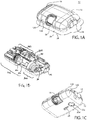
- FIGS. 1A-1C show an exemplary drug delivery device according to at least one embodiment of the present invention.
- the drug delivery device may be utilized to administer delivery of a drug treatment into a body of a user.
- the drug pump 10 includes a pump housing 12.
- Pump housing 12 may include one or more housing subcomponents which are fixedly engageable to facilitate easier manufacturing, assembly, and operation of the drug pump.
- drug pump 10 includes a pump housing 12 which includes an upper housing 12A and a lower housing 12B.
- the drug pump may further include an activation mechanism 14, a status indicator 16, and a window 18.
- Window 18 may be any translucent or transmissive surface through which the operation of the drug pump may be viewed.
- drug pump further includes assembly platform 20, sterile fluid conduit 30, drive mechanism 100 having drug container 50, insertion mechanism 200, fluid pathway connection 300, and power and control system 400.
- One or more of the components of such drug pumps may be modular in that they may be, for example, pre-assembled as separate components and configured into position onto the assembly platform 20 of the drug pump 10 during manufacturing.
- the pump housing 12 contains all of the device components and provides a means of removably attaching the device 10 to the skin of the user.
- the pump housing 12 also provides protection to the interior components of the device 10 against environmental influences.
- the pump housing 12 is ergonomically and aesthetically designed in size, shape, and related features to facilitate easy packaging, storage, handling, and use by users who may be untrained and/or physically impaired.
- the external surface of the pump housing 12 may be utilized to provide product labeling, safety instructions, and the like.
- housing 12 may include certain components, such as status indicator 16 and window 18, which may provide operation feedback to the user.
- the drug pump 10 provides an activation mechanism 14 that is displaced by the user to trigger the start command to the power and control system 400.
- the activation mechanism is a start button 14 that is located through the pump housing 12, such as through an aperture between upper housing 12A and lower housing 12B, and which contacts a control arm 40 of the power and control system 400.
- the start button 14 may be a push button, and in other embodiments, may be an on/off switch, a toggle, or any similar activation feature known in the art.
- the pump housing 12 also provides a status indicator 16 and a window 18.
- one or more of the activation mechanism 14, the status indicator 16, the window 18, and combinations thereof may be provided on the upper housing 12A or the lower housing 12B such as, for example, on a side visible to the user when the drug pump 10 is placed on the body of the user.
- Housing 12 is described in further detail hereinafter with reference to other components and embodiments of the present invention.
- Drug pump is configured such that, upon activation by a user by depression of the activation mechanism, the drug pump is initiated to: insert a fluid pathway into the user; enable, connect, or open necessary connections between a drug container, a fluid pathway, and a sterile fluid conduit; and force drug fluid stored in the drug container through the fluid pathway and fluid conduit for delivery into a user.
- One or more optional safety mechanisms may be utilized, for example, to prevent premature activation of the drug pump.
- an optional on-body sensor 24 shown in FIG. 1C ) may be provided in one embodiment as a safety feature to ensure that the power and control system 400, or the activation mechanism, cannot be engaged unless the drug pump 10 is in contact with the body of the user.
- the on-body sensor 24 is located on the bottom of lower housing 12B where it may come in contact with the user's body. Upon displacement of the on-body sensor 24, depression of the activation mechanism is permitted. Accordingly, in at least one embodiment the on-body sensor 24 is a mechanical safety mechanism, such as for example a mechanical lock out, that prevents triggering of the drug pump 10 by the activation mechanism 14. In another embodiment, the on-body sensor may be an electro-mechanical sensor such as a mechanical lock out that sends a signal to the power and control system 400 to permit activation.
- the on-body sensor can be electrically based such as, for example, a capacitive- or impedance-based sensor which must detect tissue before permitting activation of the power and control system 400.
- the drug pump 10 utilizes one or more mechanical on-body sensors. Additional integrated safety mechanisms are described herein with reference to other components of the novel drug pumps.
- the power and control system 400 includes a power source, which provides the energy for various electrical components within the drug pump, one or more feedback mechanisms, a microcontroller, a circuit board, one or more conductive pads, and one or more interconnects. Other components commonly used in such electrical systems may also be included, as would be appreciated by one having ordinary skill in the art.
- the one or more feedback mechanisms may include, for example, audible alarms such as piezo alarms and/or light indicators such as light emitting diodes (LEDs).
- the microcontroller may be, for example, a microprocessor.
- the power and control system 400 controls several device interactions with the user and interfaces with the drive mechanism 100.
- the power and control system 400 interfaces with the control arm 40 to identify when the on-body sensor 24 and/or the activation mechanism 14 have been activated.
- the power and control system 400 may also interface with the status indicator 16 of the pump housing 12, which may be a transmissive or translucent material which permits light transfer, to provide visual feedback to the user.
- the power and control system 400 interfaces with the drive mechanism 100 through one or more interconnects to relay status indication, such as activation, drug delivery, and end-of-dose, to the user.
- Such status indication may be presented to the user via auditory tones, such as through the audible alarms, and/or via visual indicators, such as through the LEDs.
- control interfaces between the power and control system and the other components of the drug pump are not engaged or connected until activation by the user. This is a desirable safety feature that prevents accidental operation of the drug pump and may additionally maintain the energy contained in the power source during storage, transportation, and the like.
- the power and control system 400 may be configured to provide a number of different status indicators to the user.
- the power and control system 400 may be configured such that after the on-body sensor and/or trigger mechanism have been pressed, the power and control system 400 provides a ready-to-start status signal via the status indicator 16 if device start-up checks provide no errors. After providing the ready-to-start status signal and, in an embodiment with the optional on-body sensor, if the on-body sensor remains in contact with the body of the user, the power and control system 400 will power the drive mechanism 100 to begin delivery of the drug treatment through the fluid pathway connection 300 and sterile fluid conduit 30.
- the insertion mechanism 200 and the fluid pathway connection 300 may be caused to activate directly by user operation of the activation mechanism 14.
- the power and control system 400 is configured to provide a dispensing status signal via the status indicator 16. After the drug has been administered into the body of the user and after the end of any additional dwell time, to ensure that substantially the entire dose has been delivered to the user, the power and control system 400 may provide an okay-to-remove status signal via the status indicator 16. This may be independently verified by the user by viewing the drive mechanism and drug dose delivery through the window 18 of the pump housing 12. Additionally, the power and control system 400 may be configured to provide one or more alert signals via the status indicator 16, such as for example alerts indicative of fault or operation failure situations.
- the power and control system 400 may additionally be configured to accept various inputs from the user to dynamically control the drive mechanisms 100 to meet a desired drug delivery rate or profile.
- the power and control system 400 may receive inputs, such as from partial or full activation, depression, and/or release of the activation mechanism 14, to set, initiate, stop, or otherwise adjust the control of the drive mechanism 100 via the power and control system 400 to meet the desired drug delivery rate or profile.
- the power and control system 400 may be configured to receive such inputs to adjust the drug dose volume; to prime the drive mechanism, fluid pathway connection, and fluid conduit; and/or to start, stop, or pause operation of the drive mechanism 100.
- Such inputs may be received by the user directly acting on the drug pump 10, such as by use of the activation mechanism 14 or a different control interface, or the system 400 may be configured to receive such inputs from a remote control device. Additionally or alternatively, such inputs may be pre-programmed.
- activation delays may be utilized during drug delivery.
- one such delay optionally included within the system configuration is a dwell time which ensures that substantially the entire drug dose has been delivered before signaling completion to the user.
- activation of the device may require a delayed depression (i.e., pushing) of the activation mechanism 14 of the drug pump 10 prior to drug pump activation.
- the system may include a feature which permits the user to respond to the end-of-dose signals and to deactivate or power-down the drug pump. Such a feature may similarly require a delayed depression of the activation mechanism, to prevent accidental deactivation of the device.
- An additional safety feature may be integrated into the activation mechanism to prevent partial depression and, therefore, partial activation of the drug pumps.
- the activation mechanism and/or power and control system may be configured such that the device is either completely off or completely on, to prevent partial activation.
- a suitable fluid pathway connection includes a sterile fluid conduit, a piercing member, and a sterile sleeve attached to a drug container or a sliding pierceable seal integrated within a drug container.
- the fluid pathway connection may further include one or more flow restrictors.
- the fluid pathway connection 300 is enabled to connect the sterile fluid conduit 30 to the drug container of the drive mechanism 100.
- Such connection may be facilitated by a piercing member, such as a needle, penetrating a pierceable seal of the drug container of the drive mechanism 100.
- the sterility of this connection may be maintained by performing the connection within a flexible sterile sleeve.
- the fluid pathway between drug container and insertion mechanism is complete to permit drug delivery into the body of the user.
- the piercing member of the fluid pathway connection is caused to penetrate the pierceable seal of the drug container of the drive mechanism by direct action of the user, such as by depression of the activation mechanism by the user.
- the activation mechanism itself may bear on the fluid pathway connection such that displacement of the activation mechanism from its original position also causes displacement of the fluid pathway connection.
- the fluid pathway connection may be substantially similar to that described in International Patent Application No. PCT/US2012/054861 , which is included by reference herein in its entirety for all purposes.
- connection is enabled by the user depressing the activation mechanism and, thereby, driving the piercing member through the pierceable seal, because this prevents fluid flow from the drug container until desired by the user.
- a compressible sterile sleeve may be fixedly attached between the cap of the drug container and the connection hub of the fluid pathway connection.
- the piercing member may reside within the sterile sleeve until a connection between the fluid connection pathway and the drug container is desired.
- the sterile sleeve may be sterilized to ensure the sterility of the piercing member and the fluid pathway prior to activation.
- a drug container may have a drug chamber within a barrel between a pierceable seal and a plunger seal.
- a drug fluid is contained in the drug chamber.
- a drive mechanism Upon activation of the device by the user, a drive mechanism asserts a force on a plunger seal contained in the drug container. As the plunger seal asserts a force on the drug fluid and any air/gas gap or bubble, a combination of pneumatic and hydraulic pressure builds by compression of the air/gas and drug fluid and the force is relayed to the sliding pierceable seal.
- the integrated sterile fluid pathway connection is connected (i.e., the fluid pathway is opened) by the combination pneumatic/hydraulic force of the air/gas and drug fluid within the drug chamber created by activation of a drive mechanism.
- drug fluid is permitted to flow from the drug container, through the integrated sterile fluid pathway connection, sterile fluid conduit, and insertion mechanism, and into the body of the user for drug delivery.
- the fluid flows through only a manifold and a cannula and/or needle of the insertion mechanism, thereby maintaining the sterility of the fluid pathway before and during drug delivery.
- the drug pump is capable of delivering a range of drugs with different viscosities and volumes.
- the drug pump is capable of delivering a drug at a controlled flow rate (speed) and/or of a specified volume.
- the drug delivery process is controlled by one or more flow restrictors within the fluid pathway connection and/or the sterile fluid conduit.
- other flow rates may be provided by varying the geometry of the fluid flow path or delivery conduit, varying the speed at which a component of the drive mechanism advances into the drug container to dispense the drug therein, or combinations thereof. Still further details about the fluid pathway connection 300 and the sterile fluid conduit 30 are provided hereinafter in later sections in reference to other embodiments.
- a number of insertion mechanisms may be utilized within the drug pumps of the present invention.
- the pump-type delivery devices of the present invention may be connected in fluid flow communication to a patient or user, for example, through any suitable hollow tubing.
- a solid bore needle may be used to pierce the skin of the patient and place a hollow cannula at the appropriate delivery position, with the solid bore needle being removed or retracted prior to drug delivery to the patient.
- the fluid can be introduced into the body through any number of means, including but not limited to: an automatically inserted needle, cannula, micro-needle array, or infusion set tubing.
- a number of mechanisms may also be employed to activate the needle insertion into the patient.
- a biasing member such as a spring may be employed to provide sufficient force to cause the needle and cannula to pierce the skin of the patient.
- the same spring, an additional spring, or another similar mechanism may be utilized to retract the needle from the patient.
- the insertion mechanism may generally be as described in International Patent Application No. PCT/US2012/53174 , which is included by reference herein in its entirety for all purposes.
- Such a configuration may be utilized for insertion of the drug delivery pathway into, or below, the skin (or muscle) of the patient in a manner that minimizes pain to the patient.
- Other known methods for insertion of a fluid pathway may be utilized and are contemplated within the bounds of the present invention.
- the insertion mechanism 200 includes an insertion mechanism housing having one or more lockout windows, and a base for connection to the assembly platform and/or pump housing (as shown in FIG. 1B and FIG. 1C ).
- the connection of the base to the assembly platform 20 may be, for example, such that the bottom of the base is permitted to pass-through a hole in the assembly platform to permit direct contact of the base to the body of the user.
- the bottom of the base may include a sealing membrane that is removable prior to use of the drug pump 10.
- the insertion mechanism may further include one or more insertion biasing members, a needle, a retraction biasing member, a cannula, and a manifold.
- the manifold may connect to sterile fluid conduit 30 to permit fluid flow through the manifold, cannula, and into the body of the user during drug delivery.
- needle is intended to refer to a variety of needles including but not limited to conventional hollow needles, such as a rigid hollow steel needles, and solid core needles more commonly referred to as “trocars.”
- the needle is a 27 gauge solid core trocar and in other embodiments, the needle may be any size needle suitable to insert the cannula for the type of drug and drug administration (e.g., subcutaneous, intramuscular, intradermal, etc.) intended.
- a sterile boot may be utilized within the needle insertion mechanism.
- the sterile boot is a collapsible sterile membrane that is in fixed engagement at a proximal end with the manifold and at a distal end with the base.
- the sterile boot is maintained in fixed engagement at a distal end between base and insertion mechanism housing.
- Base includes a base opening through which the needle and cannula may pass-through during operation of the insertion mechanism, as will be described further below. Sterility of the cannula and needle are maintained by their initial positioning within the sterile portions of the insertion mechanism. Specifically, as described above, needle and cannula are maintained in the sterile environment of the manifold and sterile boot.
- the base opening of base may be closed from non-sterile environments as well, such as by for example a sealing membrane 254 (shown in FIG. 1C ).
- the insertion mechanism is initially locked into a ready-to-use stage by lockout pin(s) which are initially positioned within lockout windows of the insertion mechanism housing.
- lockout pin(s) which are initially positioned within lockout windows of the insertion mechanism housing.
- insertion biasing member and retraction biasing member are each retained in their compressed, energized states.
- the lockout pin(s) 208 may be directly displaced by user depression of the activation mechanism 14.
- the activation mechanism 14 may be depressed to initiate the drug pump.
- Depression of the activation mechanism 14 may directly cause translation or displacement of control arm 40 and directly or indirectly cause displacement of lockout pin(s) 208 from their initial position within locking windows 202A of insertion mechanism housing 202.
- Displacement of the lockout pin(s) 208 permits insertion biasing member to decompress from its initial compressed, energized state. This decompression of the insertion biasing member drives the needle and the cannula into the body of the user.
- the retraction biasing member is permitted to expand in the proximal direction from its initial energized state. This axial expansion in the proximal direction of the retraction biasing member retracts the needle, while maintaining the cannula in fluid communication with the body of the user.
- the insertion mechanism may be used to insert a needle and cannula into the user and, subsequently, retract the needle while retaining the cannula in position for drug delivery to the body of the user.
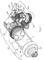
- drive mechanism 100 includes a drive housing 130, and a drug container 50 having a cap 52, a pierceable seal (not visible), a barrel 58, and a plunger seal 60.
- the seals described herein may be comprised of a number of materials but are, in a preferred embodiment, comprised of one or more elastomers or rubbers.
- the drive mechanism may further include a connection mount 54 to guide the insertion of the piercing member of the fluid pathway connection into the barrel 58 of the drug container 50.
- the drive mechanism 100 may further contain one or more drive biasing members, one or more release mechanisms, and one or more guides, as are described further herein.
- the components of the drive mechanism function to force a fluid from the drug container out through the pierceable seal, or preferably through the piercing member of the fluid pathway connection, for delivery through the fluid pathway connection, sterile fluid conduit, and insertion mechanism into the body of the user.
- the drive mechanism 100 employs one or more compression springs as the biasing member(s).
- the power and control system may be actuated to directly or indirectly release the compression spring(s) from an energized state.
- the compression spring(s) may bear against and act upon the plunger seal to force the fluid drug out of the drug container.
- the compression spring may bear against and act upon a piston which, in turn, acts upon the plunger seal to force the fluid drug out of the drug container.
- the fluid pathway connection may be connected through the pierceable seal prior to, concurrently with, or after activation of the drive mechanism to permit fluid flow from the drug container, through the fluid pathway connection, sterile fluid conduit, and insertion mechanism, and into the body of the user for drug delivery.
- the fluid flows through only a manifold and a cannula of the insertion mechanism, thereby maintaining the sterility of the fluid pathway before and during drug delivery.
- the drive mechanism 100 includes a drug container 50 having a cap 52, a pierceable seal (not visible), a barrel 58, and a plunger seal 60, and optionally a connection mount 54.
- the drug container 50 is mounted to a distal end of a drive housing 130.
- a cover sleeve 140 may be utilized between the drive biasing member 122 and the interface surface 110C of the piston 110 to, for example, promote more even distribution of force from the drive biasing member 122 to the piston 110, prevent buckling of the drive biasing member 122, and/or hide biasing member from user view.
- Interface surface 110C of piston 110 is caused to rest substantially adjacent to, or in contact with, a proximal end of seal 60.
- the piston 110A, 110B may be comprised of two components and have an interface surface 110C to contact the plunger seal.
- a tether, ribbon, string, or other retention strap (referred to herein as the "tether" 512) may be connected at one end to the piston 110A, 110B.
- the tether 512 may be connected to the piston 110A, 110B by retention between the two components of the piston 110A, 110B when assembled.
- the tether 512 is connected at another end to a winch drum 520 of a delivery control mechanism 500.
- the delivery control mechanism 500 functions to control, meter, provide resistance, or otherwise prevent free axial translation of the piston 110A, 110B and plunger seal 60 utilized to force a drug substance out of a drug container 50. Accordingly, the delivery control mechanism 500 and the drive mechanism 100 (collectively referred to herein as the "controlled delivery drive mechanism") together function to control the rate or profile of drug delivery to the user.
- the delivery control mechanisms 500 of the present invention do not drive the delivery of fluid substances from the drug chamber 21.
- the delivery of fluid substances from the drug chamber 21 is caused by the expansion of the biasing member 122 from its initial energized state acting upon the piston 110A, 110B and plunger seal 60.
- the delivery control mechanisms 500 instead function to provide resistance to the free motion of the piston 110A, 110B and plunger seal 60 as they are pushed by the expansion of the biasing member 122 from its initial energized state.
- the motor 530 is utilized only to control, meter, provide resistance, or otherwise prevent free axial translation of the plunger seal, instead of driving the translation of the plunger seal, a smaller and/or more energy efficient motor may be utilized by the novel embodiments of the present invention.
- the delivery control mechanism 500 does not drive the delivery but only controls the delivery motion.
- the tether limits or otherwise restrains the motion of the piston 110, 110B and plunger seal 60, but does not apply the force for the delivery.
- the controlled delivery drive mechanisms and drug pumps of the present invention include a motor 530 indirectly or directly connected to a tether metering the axial translation of the piston 110A, 110B and plunger seal 60, which are being driven to axially translate by the biasing member 122.
- the motor 530 may, accordingly, be selected from a variety of electromechanical sources capable of incremental motion, such as brushed DC motors, EC motors, stepper motors, solenoids, or other technologies that can produce controlled motion. In at least one embodiment, the motor is most preferably a stepper motor.
- the components of the drive mechanism 100 upon activation, may be used to drive axial translation in the distal direction of the plunger seal 60 of the drug container 50.
- the drive mechanism 100 may include one or more compliance features which enable additional axial translation of the plunger seal 60 to, for example, ensure that substantially the entire drug dose has been delivered to the user.
- the plunger seal 60 itself, may have some compressibility permitting a compliance push of drug fluid from the drug container.
- the novel controlled delivery drive mechanisms of the present invention may optionally integrate status indication into the drug dose delivery.
- the status of the drive mechanism before, during, and after operation can be relayed to the power and control system to provide feedback to the user.
- Such feedback may be tactile, visual, and/or auditory, as described above, and may be redundant such that more than one signal or type of feedback is provided to the user during use of the device.
- the user may be provided an initial feedback to identify that the system is operational and ready for drug delivery.
- the system may then provide one or more drug delivery status indications to the user.
- the drive mechanism and drug pump may provide an end-of-dose indication. As the end-of-dose indication is tied to the piston reaching the end of its axial translation, the drive mechanism and drug pump provide a true end-of-dose indication to the user.
- an end-of-dose status indication may be provided to the user once the status reader 544 contacts or recognizes the final status trigger 512A positioned on the tether 512 that would contact the status reader 544 at the end of axial travel of the piston 110A, 110B and plunger 60 within the barrel 58 of the drug container 50.
- the tether 512 may have one or more status triggers 512A, such as electrical contacts, optical markings, or electromechanical pins or recesses, which are capable of contacting or being recognized by a status reader 544.
- the status reader 544 may be, for example, an electrical switch reader to contact the corresponding electrical contacts, an optical reader to recognize the corresponding optical markings, or a mechanical or electromechanical reader configured to contact corresponding pins, holes, or similar aspects on the tether.
- the status triggers 512A may be positioned along the tether 512 to be read or recognized at positions which correspond with the beginning and end of drug delivery, as well as at desired increments during drug delivery.
- the rate or profile of drug delivery to the user is controlled by the motor 530, gear assembly, and winch drum 520 releasing the tether 512 and permitting expansion of the biasing member 122 and axial translation of the piston 110A, 110B and plunger seal 60.
- the status triggers 512A of the tether 512 are contacted or recognized by the status reader 544 and the status of the drive mechanism before, during, and after operation can be relayed to the power and control system to provide feedback to the user.
- the frequency of the incremental status indication may be varied as desired.
- a range of status readers 544 may be utilized depending on the status triggers 512A utilized by the system.
- the status reader 544 may apply a tensioning force to the tether 512.
- the tether 512 goes slack and the status reader 544 is permitted to rotate about a fulcrum (shown in FIG.6 as a cylindrical protrusion from the side of the status reader 544). This rotation may operate an electrical or electromechanical switch, for example a switch within sensor 540, signaling slack in the tether 512 to the power and control system 400.
- the status gear 528 may act as an encoder along with sensor 540.
- the sensor/encoder combination is used to provide feedback of motor rotation, which in turn can be calibrated to the position of piston 110 when there is no slack in the tether 512.
- the status reader 544 and sensor/encoder 540 provide positional feedback, end-of-dose signal, and error indication, such as an occlusion, by observing slack in the tether 512 prior to reaching the expected number of motor rotations as counted by the sensor/encoder 540.
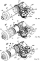
- FIG. 4A shows an isometric view of the drive mechanism, according to at least a first embodiment, during its initial locked stage.
- a fluid such as a drug fluid
- a fluid may be contained within barrel 58, in a drug chamber 21 between plunger seal 60 and pierceable seal (not visible), for delivery to a user.
- the pierceable seal is adjacent or retained at least partially within cap 52.
- a fluid pathway connection may be connected to the drug container through the pierceable seal 56.
- this fluid connection may be facilitated by a piercing member of the fluid pathway connection which pierces the pierceable seal and completes the fluid pathway from the drug container, through the fluid pathway connection, the fluid conduit, the insertion mechanism, and the cannula for delivery of the drug fluid to the body of the user.
- one or more locking mechanisms may retain the biasing member 122 in an initial energized position within piston 110A, 110B. Directly or indirectly upon activation of the device by the user, the locking mechanism may be removed to permit operation of the drive mechanism.
- the piston 110 and biasing member 122 are both initially in a compressed, energized state behind the plunger seal 60.
- biasing member 122 may be maintained in this state until activation of the device between internal features of drive housing 130 and interface surface 110C of piston 110A, 110B.
- biasing member 122 is permitted to expand (i.e., decompress) axially in the distal direction (i.e., in the direction of the hatched arrow).
- Such expansion causes the biasing member 122 to act upon and distally translate interface surface 110C and piston 110, thereby distally translating plunger seal 60 to push drug fluid out of the drug chamber 21 of barrel 58.
- an end-of-dose status indication may be provided to the user once the status reader 544 contacts or recognizes a status trigger 512A positioned on the tether 512 to substantially correspond with the end of axial travel of the piston 110A, 110B and plunger seal 60 within the barrel 58 of the drug container 50.
- the status triggers 512A are positioned along the tether 512 at various increments, such as increments which correspond to certain volume measurement, to provide incremental status indication to the user.
- the status reader is an optical status reader configured to recognize the corresponding optical status triggers on the tether. As would be understood by an ordinarily skilled artisan, such optical status triggers may be markings which are recognizable by the optical status reader.
- the status reader is a mechanical or electromechanical reader configured to physically contact corresponding pins, holes, or similar aspects on the tether. Electrical contacts could similarly be utilized on the tether as status indicators which contact or are otherwise recognized by the corresponding electrical status reader.
- the status triggers 512A may be positioned along the tether 512 to be read or recognized at positions which correspond with the beginning and end of drug delivery, as well as at desired increments during drug delivery.
- FIG. 5B shows a cross-sectional view of the view shown in FIG.
- tether 512 passes substantially axially through the drive mechanism housing 130, the biasing member 122, and connects to the piston 110 A, 110B to restrict the axial translation of the piston 110A, 110B and the plunger seal 60 that resides adjacent thereto.
- the delivery control mechanisms 500 of the present invention do not drive the delivery of fluid substances from the drug chamber 21.
- the delivery of fluid substances from the drug chamber 21 is caused by the expansion of the biasing member 122 from its initial energized state acting upon the piston 110A, 110B and plunger seal 60.
- the delivery control mechanisms 500 instead function to provide resistance to the free motion of the piston 110A, 110B and plunger seal 60 as they are pushed by the expansion of the biasing member 122 from its initial energized state.
- the biasing member 122 is permitted to continue its expansion from its energized state and drive the piston 110A, 110B and plunger seal 60 until the plunger seal 60 has substantially contacted the pierceable seal 56. This is visible in the cross-sectional view provided in FIG. 5C . At this point, substantially all of the drug substance has been pushed out of the drug chamber 21 through the fluid pathway connection 300 for drug delivery to the user.
- a status trigger 512A may be configured along the tether 512 to correspond with this position of the piston 110A, 110B, such that, as the piston 110A, 110B reaches its end of axial travel, a status trigger 512A is read or recognized by the status reader 544 to provide true end-of-dose indication to the user.
- the status triggers 512A may be positioned along the tether 512 to be read or recognized at positions which correspond with the beginning and end of drug delivery, as well as at desired increments during drug delivery.
- the controlled delivery drive mechanisms and/or drug pumps of the present invention may additionally enable a compliance push to ensure that substantially all of the drug substance has been pushed out of the drug chamber 21.
- the plunger seal 60 itself, may have some compressibility permitting a compliance push of drug fluid from the drug container.
- a pop-out plunger seal i.e., a plunger seal that is deformable from an initial state
- the plunger seal may be caused to deform or "pop-out" to provide a compliance push of drug fluid from the drug container, as shown in FIG. 5C .
- an electromechanical status switch and interconnect assembly may be utilized to contact, connect, or otherwise enable a transmission to the power and control system to signal end-of-dose to the user.
- the status switch may be located distal to the pierceable seal 56 and the interconnect located proximal to the plunger seal 60 such that, upon substantially complete axial translation (and optional compliance push) of the plunger seal 60 within the barrel 58, the status switch and interconnect coordinate to enable a transmission to the power and control system to signal end-of-dose to the user.
- This configuration further enables true end-of-dose indication to the user.
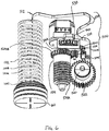
- FIG. 6 shows a perspective view of certain components of a controlled delivery drive mechanism, according to at least one embodiment of the present invention.
- the controlled delivery drive mechanism incorporates an incremental status indicator mechanism having a status reader and one or more corresponding status triggers.
- the gear assembly of the delivery control mechanism 500 utilizes a motor 530 with pinion 530A.
- the pinion 530A contacts a first gear 526A of a compound gear 526
- the second gear 526B of the compound gear 526 contacts a gear aspect 524B of a worm gear 524.
- the worm aspect 524A of the worm gear 524 contacts a drum gear 522 which is connected to a winch drum 520.
- the tether 512 is at least partially wrapped around the winch drum 520.
- a status reader 544 may read or recognize one or more corresponding status triggers 512A on the tether 512 to provide incremental status indication before, during, and after operation of the controlled delivery drive mechanism.
- the drive mechanism shown in FIG. 6 may utilize a mechanical status reader 544 which is physically contacted by ridges, holes, or other aspects incrementally spaced on the tether 512 to correspond with desired status indications (e.g., volume delivered, volume remaining, changes in delivery rates or profiles, etc.).
- desired status indications e.g., volume delivered, volume remaining, changes in delivery rates or profiles, etc.
- the status reader 544 causes the sensor 540 to measure the position of the status gear 528 and transmit a signal to the power and control system for status indication to the user.
- optical status readers and corresponding triggers, electromechanical status readers and corresponding triggers, and/or mechanical status readers and corresponding triggers may all be utilized by the embodiments of the present invention to provide incremental status indication to the user.
- Assembly and/or manufacturing of controlled delivery drive mechanism 100, drug delivery pump 10, or any of the individual components may utilize a number of known materials and methodologies in the art.
- a number of known cleaning fluids such as isopropyl alcohol and hexane may be used to clean the components and/or the devices.
- a number of known adhesives or glues may similarly be employed in the manufacturing process.
- known siliconization and/or lubrication fluids and processes may be employed during the manufacture of the novel components and devices.
- known sterilization processes may be employed at one or more of the manufacturing or assembly stages to ensure the sterility of the final product.
- the drive mechanism may be assembled in a number of methodologies.
- the drug container 50 may first be assembled and filled with a fluid for delivery to the user.
- the drug container 50 includes a cap 52, a pierceable seal 56, a barrel 58, and a plunger seal 60.
- the pierceable seal 56 may be fixedly engaged between the cap 52 and the barrel 58, at a distal end of the barrel 58.
- the barrel 58 may be filled with a drug fluid through the open proximal end prior to insertion of the plunger seal 60 from the proximal end of the barrel 58.
- An optional connection mount 54 may be mounted to a distal end of the pierceable seal 56.
- the connection mount 54 may guide the insertion of the piercing member of the fluid pathway connection into the barrel 58 of the drug container 50.
- the drug container 50 may then be mounted to a distal end of drive housing 130.
- a drive biasing member 122 may be inserted into a distal end of the drive housing 130.
- a cover sleeve 140 may be inserted into a distal end of the drive housing 130 to substantially cover biasing member 122.
- a piston may be inserted into the distal end of the drive housing 130 such that it resides at least partially within an axial pass-through of the biasing member 122 and the biasing member 122 is permitted to contact a piston interface surface 110C of piston 110A, 110B at the distal end of the biasing member 122.
- An optional cover sleeve 140 may be utilized to enclose the biasing member 122 and contact the piston interface surface 110C of piston 110A, 110B.
- the piston 110A, 110B and drive biasing member 122, and optional cover sleeve 140 may be compressed into drive housing 130.
- Such assembly positions the drive biasing member 122 in an initial compressed, energized state and preferably places a piston interface surface 110C in contact with the proximal surface of the plunger seal 60 within the proximal end of barrel 58.
- the piston, piston biasing member, contact sleeve, and optional components may be compressed and locked into the ready-to-actuate state within the drive housing 130 prior to attachment or mounting of the drug container 50.
- the tether 512 is pre-connected to the proximal end of the piston 110A, 110B and passed through the axial aperture of the biasing member 122 and drive mechanism 130, and then wound through the interior of the drug pump with the other end of the tether 512 wrapped around the winch drum 520 of the delivery control mechanism 500.
- a fluid pathway connection and specifically a sterile sleeve of the fluid pathway connection, may be connected to the cap and/or pierceable seal of the drug container.
- a fluid conduit may be connected to the other end of the fluid pathway connection which itself is connected to the insertion mechanism such that the fluid pathway, when opened, connected, or otherwise enabled travels directly from the drug container, fluid pathway connection, fluid conduit, insertion mechanism, and through the cannula for drug delivery into the body of a user.
- the components which constitute the pathway for fluid flow are now assembled. These components may be sterilized, by a number of known methods, and then mounted either fixedly or removably to an assembly platform or housing of the drug pump, as shown in FIG. 1B .
- drive mechanism 100 or drug pump 10 may include one or more batteries utilized to power the motor, drive mechanisms, and drug pumps of the present invention. A range of batteries known in the art may be utilized for this purpose.
- upper or lower housings may optionally contain one or more transparent or translucent windows 18, as shown in FIG. 1A , to enable the user to view the operation of the drug pump 10 or verify that drug dose has completed.
- the drug pump 10 may contain an adhesive patch 26 and a patch liner 28 on the bottom surface of the housing 12. The adhesive patch 26 may be utilized to adhere the drug pump 10 to the body of the user for delivery of the drug dose.
- the adhesive patch 26 may have an adhesive surface for adhesion of the drug pump to the body of the user.
- the adhesive surface of the adhesive patch 26 may initially be covered by a non-adhesive patch liner 28, which is removed from the adhesive patch 26 prior to placement of the drug pump 10 in contact with the body of the user. Removal of the patch liner 28 may further remove the sealing membrane 254 of the insertion mechanism 200, opening the insertion mechanism to the body of the user for drug delivery (as shown in FIG. 1C ).
- controlled delivery drive mechanism 100 and drug pump 10 may be modified while remaining functionally within the breadth and scope of the present invention.
- the housing of drug pump 10 is shown as two separate components upper housing 12A and lower housing 12B, these components may be a single unified component.
- a glue, adhesive, or other known materials or methods may be utilized to affix one or more components of the controlled delivery drive mechanism and/or drug pump to each other.
- one or more components of the controlled delivery drive mechanism and/or drug pump may be a unified component.
- the upper housing and lower housing may be separate components affixed together by a glue or adhesive, a screw fit connection, an interference fit, fusion joining, welding, ultrasonic welding, and the like; or the upper housing and lower housing may be a single unified component.
- the controlled delivery drive mechanisms and drug pumps disclosed herein provide an efficient and easily-operated system for automated drug delivery from a drug container.
- the novel embodiments described herein provide drive mechanisms for the controlled delivery of drug substances and drug delivery pumps which incorporate such controlled delivery drive mechanisms.
- the drive mechanisms of the present invention control the rate of drug delivery by metering, providing resistance, or otherwise preventing free axial translation of the plunger seal utilized to force a drug substance out of a drug container and, thus, are capable of delivering drug substances at variable rates and/or delivery profiles.
- the drive mechanisms of the present invention provide integrated status indication features which provide feedback to the user before, during, and after drug delivery. For example, the user may be provided an initial feedback to identify that the system is operational and ready for drug delivery.
- the system may then provide one or more drug delivery status indications to the user.
- the drive mechanism and drug pump may provide an end-of-dose indication.
- the novel controlled delivery drive mechanisms of the present invention may be directly or indirectly activated by the user.
- the novel configurations of the controlled delivery drive mechanism and drug pumps of the present invention maintain the sterility of the fluid pathway during storage, transportation, and through operation of the device. Because the path that the drug fluid travels within the device is entirely maintained in a sterile condition, only these components need be sterilized during the manufacturing process. Such components include the drug container of the drive mechanism, the fluid pathway connection, the sterile fluid conduit, and the insertion mechanism.
- the power and control system, the assembly platform, the control arm, the activation mechanism, the housing, and other components of the drug pump do not need to be sterilized. This greatly improves the manufacturability of the device and reduces associated assembly costs. Accordingly, the devices of the present invention do not require terminal sterilization upon completion of assembly.
- Manufacturing of a drug pump includes the step of attaching both the controlled delivery drive mechanism and drug container, either separately or as a combined component, to an assembly platform or housing of the drug pump.
- the method of manufacturing further includes attachment of the fluid pathway connection, drug container, and insertion mechanism to the assembly platform or housing.
- the additional components of the drug pump, as described above, including the power and control system, the activation mechanism, and the control arm may be attached, preformed, or pre-assembled to the assembly platform or housing.
- An adhesive patch and patch liner may be attached to the housing surface of the drug pump that contacts the user during operation of the device.
- a method of operating the drug pump includes the steps of: activating, by a user, the activation mechanism; displacing a control arm to actuate an insertion mechanism; and actuating a power and control system to activate a controlled delivery drive mechanism to drive fluid drug flow through the drug pump according to a controlled rate or drug delivery profile.
- the method may further include the step of: engaging an optional on-body sensor prior to activating the activation mechanism.
- the method similarly may include the step of: establishing a connection between a fluid pathway connection to a drug container.
- the method of operation may include translating a plunger seal within the controlled delivery drive mechanism by the expansion of the biasing member acting upon a piston within a drug container to force fluid drug flow through the drug container, the fluid pathway connection, a sterile fluid conduit, and the insertion mechanism for delivery of the fluid drug to the body of a user, wherein a tether is utilized to restrain the free axial translation of the piston.
- the method of operation of the insertion mechanism and the drug pump may be better appreciated with reference to FIGS. 4A-4C and FIGS. 5A-5C , as described above.
Applications Claiming Priority (5)
| Application Number | Priority Date | Filing Date | Title |
|---|---|---|---|
| US201261694534P | 2012-08-29 | 2012-08-29 | |
| US201261731744P | 2012-11-30 | 2012-11-30 | |
| US201361748667P | 2013-01-03 | 2013-01-03 | |
| EP13762335.1A EP2890431B1 (de) | 2012-08-29 | 2013-08-29 | Antriebsmechanismen mit kontrollierter freisetzung für arzneimittelabgabepumpen |
| EP16151332.0A EP3028727B1 (de) | 2012-08-29 | 2013-08-29 | Antriebsmechanismen mit kontrollierter freisetzung für arzneimittelabgabepumpen |
Related Parent Applications (3)
| Application Number | Title | Priority Date | Filing Date |
|---|---|---|---|
| EP16151332.0A Division EP3028727B1 (de) | 2012-08-29 | 2013-08-29 | Antriebsmechanismen mit kontrollierter freisetzung für arzneimittelabgabepumpen |
| EP16151332.0A Division-Into EP3028727B1 (de) | 2012-08-29 | 2013-08-29 | Antriebsmechanismen mit kontrollierter freisetzung für arzneimittelabgabepumpen |
| EP13762335.1A Division EP2890431B1 (de) | 2012-08-29 | 2013-08-29 | Antriebsmechanismen mit kontrollierter freisetzung für arzneimittelabgabepumpen |
Publications (1)
| Publication Number | Publication Date |
|---|---|
| EP3225265A1 true EP3225265A1 (de) | 2017-10-04 |
Family
ID=49165853
Family Applications (6)
| Application Number | Title | Priority Date | Filing Date |
|---|---|---|---|
| EP17163810.9A Active EP3210636B1 (de) | 2012-08-29 | 2013-08-29 | Antriebsmechanismen für arzneimittelabgabepumpen mit gesteuerter freisetzung und variabler rate |
| EP13762335.1A Not-in-force EP2890431B1 (de) | 2012-08-29 | 2013-08-29 | Antriebsmechanismen mit kontrollierter freisetzung für arzneimittelabgabepumpen |
| EP17162587.4A Pending EP3225265A1 (de) | 2012-08-29 | 2013-08-29 | Antriebsmechanismen mit kontrollierter freisetzung für arzneimittelabgabepumpen |
| EP13762339.3A Not-in-force EP2890432B1 (de) | 2012-08-29 | 2013-08-29 | Antriebsmechanismen für arzneimittelabgabepumpen mit gesteuerter freisetzung und variabler rate |
| EP13763364.0A Active EP2890433B1 (de) | 2012-08-29 | 2013-08-29 | Antriebsmechanismen mit kontrollierter freisetzung für arzneimittelabgabepumpen |
| EP16151332.0A Not-in-force EP3028727B1 (de) | 2012-08-29 | 2013-08-29 | Antriebsmechanismen mit kontrollierter freisetzung für arzneimittelabgabepumpen |
Family Applications Before (2)
| Application Number | Title | Priority Date | Filing Date |
|---|---|---|---|
| EP17163810.9A Active EP3210636B1 (de) | 2012-08-29 | 2013-08-29 | Antriebsmechanismen für arzneimittelabgabepumpen mit gesteuerter freisetzung und variabler rate |
| EP13762335.1A Not-in-force EP2890431B1 (de) | 2012-08-29 | 2013-08-29 | Antriebsmechanismen mit kontrollierter freisetzung für arzneimittelabgabepumpen |
Family Applications After (3)
| Application Number | Title | Priority Date | Filing Date |
|---|---|---|---|
| EP13762339.3A Not-in-force EP2890432B1 (de) | 2012-08-29 | 2013-08-29 | Antriebsmechanismen für arzneimittelabgabepumpen mit gesteuerter freisetzung und variabler rate |
| EP13763364.0A Active EP2890433B1 (de) | 2012-08-29 | 2013-08-29 | Antriebsmechanismen mit kontrollierter freisetzung für arzneimittelabgabepumpen |
| EP16151332.0A Not-in-force EP3028727B1 (de) | 2012-08-29 | 2013-08-29 | Antriebsmechanismen mit kontrollierter freisetzung für arzneimittelabgabepumpen |
Country Status (15)
| Country | Link |
|---|---|
| US (5) | US9987419B2 (de) |
| EP (6) | EP3210636B1 (de) |
| JP (5) | JP6355169B2 (de) |
| KR (3) | KR20150048832A (de) |
| CN (3) | CN104602733B (de) |
| AU (3) | AU2013308699B2 (de) |
| BR (2) | BR112015003422A2 (de) |
| CA (3) | CA2881306A1 (de) |
| DK (4) | DK2890432T3 (de) |
| ES (3) | ES2615903T3 (de) |
| HK (2) | HK1211885A1 (de) |
| IL (3) | IL236958B (de) |
| MX (4) | MX364883B (de) |
| PT (4) | PT2890432T (de) |
| WO (3) | WO2014036285A2 (de) |
Families Citing this family (87)
| Publication number | Priority date | Publication date | Assignee | Title |
|---|---|---|---|---|
| PL1762259T3 (pl) | 2005-09-12 | 2011-03-31 | Unomedical As | Urządzenie wprowadzające, przeznaczone do zestawu infuzyjnego, z pierwszą i drugą jednostką sprężynową |
| MX2012011085A (es) | 2010-03-30 | 2012-10-10 | Unomedical As | Dispositivo medico. |
| US10194938B2 (en) | 2011-03-14 | 2019-02-05 | UnoMedical, AS | Inserter system with transport protection |
| US8939935B2 (en) | 2011-09-02 | 2015-01-27 | Unitract Syringe Pty Ltd | Drive mechanism for drug delivery pumps with integrated status indication |
| US9707335B2 (en) | 2011-09-02 | 2017-07-18 | Unitract Syringe Pty Ltd | Drive mechanism for drug delivery pumps with integrated status indication |
| US9814832B2 (en) | 2011-09-02 | 2017-11-14 | Unl Holdings Llc | Drive mechanism for drug delivery pumps with integrated status indication |
| US11173244B2 (en) | 2011-09-02 | 2021-11-16 | Unl Holdings Llc | Drive mechanism for drug delivery pumps with integrated status indication |
| CN103957962B (zh) | 2011-10-05 | 2017-07-07 | 犹诺医药有限公司 | 用于同时插入多个经皮部分的插入物 |
| EP2583715A1 (de) | 2011-10-19 | 2013-04-24 | Unomedical A/S | Infusionsschlauchsystem und Herstellungsverfahren |
| CA2881306A1 (en) | 2012-08-29 | 2014-03-06 | Unitract Syringe Pty Ltd | Controlled delivery drive mechanisms for drug delivery pumps |
| EP2938376A4 (de) | 2012-12-27 | 2017-01-25 | Kaleo, Inc. | Vorrichtungen, systeme und verfahren zur ortung von und interaktion mit medikamentenverabreichungssystemen |
| DE202013000411U1 (de) * | 2013-01-16 | 2013-01-24 | H & B Electronic Gmbh & Co. Kg | Dauerinfusionsvorrichtung |
| BR112015017717A2 (pt) * | 2013-01-25 | 2017-07-11 | Unitract Syringe Pty Ltd | mecanismo de acionamento de bomba de fármaco |
| US9591740B2 (en) | 2013-03-08 | 2017-03-07 | Tri Alpha Energy, Inc. | Negative ion-based neutral beam injector |
| EP3021899A1 (de) * | 2013-07-17 | 2016-05-25 | Sanofi | Antriebskonfiguration für eine wirkstofffreisetzungsvorrichtung |
| GB2516896B (en) * | 2013-08-05 | 2020-08-12 | Owen Mumford Ltd | Injection devices |
| TWI569832B (zh) * | 2013-10-23 | 2017-02-11 | 卡貝歐洲有限公司 | 藥物輸送裝置 |
| US10556059B2 (en) * | 2013-12-31 | 2020-02-11 | Biogen Ma Inc. | Infusion pump drive with compression spring |
| EP3102259B1 (de) * | 2014-02-03 | 2020-03-25 | UNL Holdings LLC | Erweiterung von kolbenstangen für spritzen |
| JP6275291B2 (ja) * | 2014-03-12 | 2018-02-07 | ウェイ,ミン | 薬物自動注射器 |
| JP6822843B2 (ja) | 2014-06-03 | 2021-01-27 | アムジエン・インコーポレーテツド | 薬物送達装置によって収集されたデータを遠隔で処理するためのシステム及び方法 |
| TWI689326B (zh) * | 2014-08-06 | 2020-04-01 | 加拿大商複製細胞生命科學公司 | 注射裝置 |
| WO2016049501A1 (en) | 2014-09-26 | 2016-03-31 | Unitract Syringe Pty Ltd | Concentric barrel drug containers and drug delivery pumps that allow mixing and delivery |
| JP2018501925A (ja) * | 2014-12-08 | 2018-01-25 | サノフイ | 駆動機構を有する薬物送達デバイス |
| JP6748655B2 (ja) * | 2014-12-08 | 2020-09-02 | サノフイSanofi | 薬物送達デバイスを組み立てる方法および薬物送達デバイス |
| GB2534599A (en) * | 2015-01-29 | 2016-08-03 | Owen Mumford Ltd | A medicament delivery device |
| JP6752808B2 (ja) | 2015-03-02 | 2020-09-09 | アムジエン・インコーポレーテツド | 無菌接続を形成する装置 |
| AU2016229138B2 (en) | 2015-03-09 | 2020-10-29 | Amgen Inc. | Drive mechanisms for drug delivery pumps |
| EP3268078B1 (de) | 2015-03-10 | 2020-11-04 | Regeneron Pharmaceuticals, Inc. | Aseptisches durchstechsystem |
| CN104815369B (zh) * | 2015-04-30 | 2017-09-05 | 于振燕 | Icu科微量注射泵装置 |
| ES2846879T3 (es) * | 2015-10-13 | 2021-07-30 | Lilly Co Eli | Sistema de detección de posición cero para dispositivo de administración de medicación |
| CN105194757B (zh) * | 2015-10-27 | 2018-04-03 | 李绪祯 | 全自动便携式输液泵及其使用方法 |
| US10449306B2 (en) * | 2015-11-25 | 2019-10-22 | Medtronics Minimed, Inc. | Systems for fluid delivery with wicking membrane |
| US10406282B2 (en) * | 2015-12-10 | 2019-09-10 | Repro-Med Systems, Inc. | System and method for a syringe micro pump with volute spring |
| CN108778370B (zh) | 2016-01-19 | 2021-10-08 | 优诺医疗有限公司 | 套管和输液装置 |
| JOP20170042B1 (ar) * | 2016-02-12 | 2022-09-15 | Amgen Inc | وسيلة توصيل عقار، طريقة تصنيعه وطريقة استخدامه |
| EP3416705B1 (de) * | 2016-02-19 | 2020-09-02 | Flextronics AP, LLC | Automatisches injektionssystem mit magnetischem antrieb |
| US10967118B2 (en) | 2016-02-19 | 2021-04-06 | Flex, Ltd. | Automatic injection device having a magnetic drive system |
| US11484695B2 (en) | 2016-03-16 | 2022-11-01 | Cosmed Pharmaceutical Co., Ltd. | Microneedle patch case |
| EP3439715B1 (de) | 2016-04-08 | 2021-03-10 | Amgen Inc. | Arzneimittelverabreichungsvorrichtung |
| EP3445421A4 (de) * | 2016-04-18 | 2020-01-01 | Medtrum Technologies Inc. | Einseitiger antriebsmechanismus für ein tragbares infusionssystem |
| US10549044B2 (en) * | 2016-06-09 | 2020-02-04 | Becton, Dickinson And Company | Spacer assembly for drug delivery system |
| CN106110434A (zh) * | 2016-06-22 | 2016-11-16 | 重庆科技学院 | 流量可调机械自动输液仪 |
| WO2018005915A1 (en) | 2016-06-30 | 2018-01-04 | West Pharmaceutical Services, Inc. | Reusable, patient controlled syringe drive device |
| KR101710887B1 (ko) * | 2016-07-04 | 2017-03-13 | 박라미 | 화장품 흡수를 위한 피부 자극기 |
| BR112019002457A2 (pt) | 2016-08-08 | 2019-05-14 | Unl Holdings Llc | dispositivo de entrega de fármaco e método para conectar uma trajetória de fluxo de fluido |
| KR101923267B1 (ko) * | 2016-08-12 | 2018-11-28 | 주식회사 동방메디컬 | 약물 카트리지 및 이를 구비하는 약물주입기 |
| US10695487B2 (en) | 2016-08-30 | 2020-06-30 | Unl Holdings Llc | Controlled delivery drive mechanisms for drug delivery pumps |
| EP3570909A1 (de) | 2017-01-17 | 2019-11-27 | West Pharma. Services Il, Ltd. | Gebogener injektor mit federantrieb |
| JP2020507841A (ja) | 2017-01-17 | 2020-03-12 | カレオ,インコーポレイテッド | 無線接続及び事象検出を伴う薬剤送達デバイス |
| US11179523B2 (en) * | 2017-01-20 | 2021-11-23 | Biogen Ma, Inc. | Smart injector |
| CN106880886B (zh) * | 2017-03-30 | 2020-01-10 | 青岛大学附属医院 | 一种输液自动换瓶装置 |
| ES2884153T3 (es) * | 2017-03-31 | 2021-12-10 | Becton Dickinson Co | Dispositivo inteligente de inyección y/o infusión portable |
| FR3065646B1 (fr) * | 2017-04-26 | 2019-06-14 | Aptar France Sas | Dispositif d'injection automatique de produit fluide |
| HUE059229T2 (hu) * | 2017-05-05 | 2022-10-28 | Regeneron Pharma | Automata befecskendezõkészülék |
| KR102239217B1 (ko) * | 2017-07-11 | 2021-04-12 | 한양대학교 산학협력단 | 흡인 압력이 일정한 의료용 흡인기 |
| AU2018302257A1 (en) * | 2017-07-19 | 2020-01-30 | Smiths Medical Asd, Inc. | Housing arrangements for infusion pumps |
| US11590279B2 (en) * | 2017-07-20 | 2023-02-28 | Flex Ltd. | Clock mechanism flow regulator |
| KR101999364B1 (ko) * | 2017-07-21 | 2019-07-12 | 서울대학교병원 | 기계식 자동 약물 투여 장치 |
| EP3658203B1 (de) | 2017-07-25 | 2022-08-31 | Amgen Inc. | Arzneimittelabgabevorrichtung mit getriebemodul und verwandtes verfahren zur montage |
| WO2019043423A1 (en) * | 2017-08-30 | 2019-03-07 | Unitract Syringe Pty Ltd | CONTROLLED ADMINISTRATION DRIVE MECHANISMS FOR DRUG DELIVERY PUMPS |
| WO2019065946A1 (ja) * | 2017-09-29 | 2019-04-04 | テルモ株式会社 | プランジャ組立体、薬液投与装置及びプランジャ組立体の駆動方法 |
| EP3694578A1 (de) | 2017-10-09 | 2020-08-19 | Amgen Inc. | Arzneimittelabgabevorrichtung mit antriebsanordnung sowie zugehöriges verfahren zur montage |
| US10994116B2 (en) * | 2018-06-30 | 2021-05-04 | Bioq Pharma Incorporated | Drug cartridge-based infusion pump |
| US11929160B2 (en) | 2018-07-16 | 2024-03-12 | Kaleo, Inc. | Medicament delivery devices with wireless connectivity and compliance detection |
| DE102018118630A1 (de) * | 2018-08-01 | 2020-02-06 | B. Braun Melsungen Ag | Infusionssystem mit Infusionspumpe und damit kuppelbaren Pumpmodul |
| CN110354338A (zh) * | 2018-09-03 | 2019-10-22 | 上海北昂医药科技股份有限公司 | 具有旋转分配及注射功能的泵阀一体装置 |
| FR3086176B1 (fr) | 2018-09-20 | 2022-11-04 | Aptar France Sas | Autoinjecteur. |
| WO2020236796A1 (en) | 2019-05-20 | 2020-11-26 | Unomedical A/S | Rotatable infusion device and methods thereof |
| US20200384184A1 (en) * | 2019-06-06 | 2020-12-10 | Orlando Health, Inc. | Wound irrigation device |
| CA3091601A1 (en) * | 2019-09-18 | 2021-03-18 | Heraeus Medical Gmbh | Device for temporarily, locally applying fluids |
| GB2587804A (en) * | 2019-09-27 | 2021-04-14 | West Pharmaceutical Services Il Ltd | Multi-rate drug delivery device and method of controlling the device |
| JP6937396B2 (ja) * | 2020-01-31 | 2021-09-22 | セイコーインスツル株式会社 | 定量送り機構及び吐出装置 |
| JP6937397B2 (ja) * | 2020-01-31 | 2021-09-22 | セイコーインスツル株式会社 | 薬液ポンプ及び薬液投与装置 |
| JP7411435B2 (ja) | 2020-02-12 | 2024-01-11 | テルモ株式会社 | 薬液投与装置 |
| JP7396920B2 (ja) | 2020-02-12 | 2023-12-12 | テルモ株式会社 | 薬液投与装置 |
| CN111282088B (zh) * | 2020-03-01 | 2021-09-03 | 杭州丽脂医疗科技有限公司和兴路医疗美容门诊部 | 精准可微调定量的自体脂肪填充装置 |
| US11120824B1 (en) | 2020-08-26 | 2021-09-14 | Seagate Technology Llc | Bolometric sensor for a heat-assisted magnetic recording device |
| CN216571055U (zh) * | 2020-08-31 | 2022-05-24 | 贝克顿·迪金森公司 | 一种旋转计量泵 |
| KR102308887B1 (ko) * | 2020-09-16 | 2021-10-05 | 부경대학교 산학협력단 | 무전력 유체 펌프 |
| WO2022090981A1 (en) * | 2020-10-28 | 2022-05-05 | Patel Karna Nikhil | Device for injecting fluid in a body |
| CN112169068A (zh) * | 2020-11-02 | 2021-01-05 | 张超 | 一种心脏供血治疗器 |
| USD1007676S1 (en) | 2021-11-16 | 2023-12-12 | Regeneron Pharmaceuticals, Inc. | Wearable autoinjector |
| WO2023132493A1 (ko) * | 2022-01-04 | 2023-07-13 | 이오플로우㈜ | 레저버 어셈블리 및 이를 포함하는 약액 주입 장치 |
| WO2023132507A1 (ko) * | 2022-01-04 | 2023-07-13 | 이오플로우㈜ | 약액 주입 장치 |
| KR20240010112A (ko) * | 2022-07-15 | 2024-01-23 | 서울대학교산학협력단 | 자동 투약 기능을 가지는 이식형 디바이스 |
| US20240108800A1 (en) * | 2022-09-30 | 2024-04-04 | Insulet Corporation | Dual wheel actuator |
Citations (4)
| Publication number | Priority date | Publication date | Assignee | Title |
|---|---|---|---|---|
| WO2002028455A1 (en) * | 2000-10-05 | 2002-04-11 | Novo Nordisk A/S | Medication delivery device with bended piston rod |
| WO2008142394A1 (en) * | 2007-05-18 | 2008-11-27 | Danby Scientific Limited | Infusion pump |
| WO2010112376A1 (en) * | 2009-03-31 | 2010-10-07 | Sanofi-Aventis Deutschland Gmbh | Improvements in and relating to medicament delivery devices |
| WO2010112377A1 (en) * | 2009-03-31 | 2010-10-07 | Sanofi-Aventis Deutschland Gmbh | Improvements in and relating to a medicament delivery devices |
Family Cites Families (204)
| Publication number | Priority date | Publication date | Assignee | Title |
|---|---|---|---|---|
| US1929774A (en) * | 1929-01-10 | 1933-10-10 | Alemite Corp | Lubricating apparatus |
| US3413974A (en) | 1963-06-26 | 1968-12-03 | Milton J. Cohen | Hypodermic syringes |
| US3336924A (en) | 1964-02-20 | 1967-08-22 | Sarnoff | Two compartment syringe package |
| US3401692A (en) | 1964-06-26 | 1968-09-17 | Micro Tek Instr Corp | Syringe provided with a lateral vent and having high compression seals within the syringe bore |
| US3631847A (en) * | 1966-03-04 | 1972-01-04 | James C Hobbs | Method and apparatus for injecting fluid into the vascular system |
| US3701345A (en) * | 1970-09-29 | 1972-10-31 | Medrad Inc | Angiographic injector equipment |
| US3886938A (en) * | 1973-10-23 | 1975-06-03 | Scala Anthony | Power operated fluid infusion device |
| US3940003A (en) | 1974-05-07 | 1976-02-24 | Pharmaco, Inc. | Safety cap for medicament vial having puncturable seal |
| US4004586A (en) | 1975-03-12 | 1977-01-25 | Baxter Travenol Laboratories, Inc. | Method and apparatus for sealed, sterile connection |
| US4048997A (en) | 1976-11-01 | 1977-09-20 | Mpl, Inc. | Syringe with actinic radiation protection |
| US4313439A (en) | 1980-03-24 | 1982-02-02 | Biotek, Inc. | Automated, spring-powered medicament infusion system |
| EP0107874B1 (de) | 1982-10-27 | 1986-11-26 | Duphar International Research B.V | Automatische Injektionsvorrichtung |
| US4685903A (en) | 1984-01-06 | 1987-08-11 | Pacesetter Infusion, Ltd. | External infusion pump apparatus |
| US4602700A (en) | 1984-06-15 | 1986-07-29 | Daltex Medical Sciences, Inc. | Fail-safe mechanical drive for syringe |
| US4676122A (en) | 1984-06-15 | 1987-06-30 | Daltex Medical Sciences, Inc. | Fail-safe mechanical drive for syringe |
| DE3439322A1 (de) | 1984-10-26 | 1986-05-07 | Infors GmbH, 8000 München | Infusionspumpe |
| EP0204977A1 (de) * | 1985-05-14 | 1986-12-17 | Ivion Corporation | Bewegungseinrichtung für Spritzen |
| JPH0236519Y2 (de) * | 1985-10-25 | 1990-10-04 | ||
| US4673400A (en) | 1986-02-10 | 1987-06-16 | Martin Ivan W | Aseptic connector assembly for conduits for sterile fluids |
| US4755173A (en) | 1986-02-25 | 1988-07-05 | Pacesetter Infusion, Ltd. | Soft cannula subcutaneous injection set |
| JPH072182B2 (ja) | 1986-04-07 | 1995-01-18 | テルモ株式会社 | 輸液ポンプ |
| JPH0515956Y2 (de) | 1987-05-27 | 1993-04-27 | ||
| US4755172A (en) | 1987-06-30 | 1988-07-05 | Baldwin Brian E | Syringe holder/driver and syringe arrangement and syringe/holder driver therefor |
| ATA228987A (de) | 1987-09-09 | 1993-07-15 | Pickhard Ewald | Injektionsvorrichtung mit einer verformbaren ampulle |
| US4921487A (en) * | 1988-09-21 | 1990-05-01 | Compagnie Financiere Saint. Nicolas | External device for injecting medicine |
| USD326611S (en) | 1988-12-09 | 1992-06-02 | Euroitalia S.R.L. | Bottle |
| US5167816A (en) | 1990-08-20 | 1992-12-01 | Abbott Laboratories | Sterile coupling device for drug container |
| US5254096A (en) | 1992-09-23 | 1993-10-19 | Becton, Dickinson And Company | Syringe pump with graphical display or error conditions |
| GB2271391B (en) * | 1992-10-12 | 1995-08-02 | Hornche Trading Co Ltd | Automatic grease dispenser |
| DE4310808C2 (de) * | 1993-04-02 | 1995-06-22 | Boehringer Mannheim Gmbh | System zur Dosierung von Flüssigkeiten |
| FR2715071B1 (fr) | 1994-01-17 | 1996-03-01 | Aguettant Lab | Injecteur automatique de médicament. |
| US5637095A (en) * | 1995-01-13 | 1997-06-10 | Minimed Inc. | Medication infusion pump with flexible drive plunger |
| US5795339A (en) | 1995-03-07 | 1998-08-18 | Becton Dickinson And Company | Catheter-advancement actuated needle retraction system |
| US6159161A (en) * | 1995-10-20 | 2000-12-12 | Hodosh; Milton | Microprocessor-controlled fluid dispensing apparatus |
| US5807334A (en) * | 1995-10-20 | 1998-09-15 | Hodosh; Milton | Fluid dispensing apparatus |
| US5800405A (en) | 1995-12-01 | 1998-09-01 | I-Flow Corporation | Syringe actuation device |
| US5858001A (en) | 1995-12-11 | 1999-01-12 | Elan Medical Technologies Limited | Cartridge-based drug delivery device |
| PL186395B1 (pl) | 1996-03-19 | 2004-01-30 | I Flow Corp | Ambulatoryjna pompa infuzyjna |
| US5851197A (en) | 1997-02-05 | 1998-12-22 | Minimed Inc. | Injector for a subcutaneous infusion set |
| US6003736A (en) * | 1997-06-09 | 1999-12-21 | Novo Nordisk A/S | Device for controlled dispensing of a dose of a liquid contained in a cartridge |
| US6019747A (en) * | 1997-10-21 | 2000-02-01 | I-Flow Corporation | Spring-actuated infusion syringe |
| US5989237A (en) | 1997-12-04 | 1999-11-23 | Baxter International Inc. | Sliding reconstitution device with seal |
| JP3356679B2 (ja) * | 1998-03-19 | 2002-12-16 | 日本サーボ株式会社 | 輸液装置 |
| JP4425465B2 (ja) | 1998-03-23 | 2010-03-03 | エラン コーポレーション ピーエルシー | 薬剤送給装置 |
| US5919167A (en) | 1998-04-08 | 1999-07-06 | Ferring Pharmaceuticals | Disposable micropump |
| DE19840992A1 (de) | 1998-09-08 | 2000-03-09 | Disetronic Licensing Ag | Drucküberwachung eines bei einer Infusion oder Injektion dosiert zu verabreichenden Produktfluids |
| US6022339A (en) | 1998-09-15 | 2000-02-08 | Baxter International Inc. | Sliding reconstitution device for a diluent container |
| US6248093B1 (en) | 1998-10-29 | 2001-06-19 | Minimed Inc. | Compact pump drive system |
| US6645177B1 (en) * | 1999-02-09 | 2003-11-11 | Alaris Medical Systems, Inc. | Directly engaged syringe driver system |
| USD430289S (en) | 1999-07-30 | 2000-08-29 | Breg, Inc. | Infusion pump for administering a fluid medication |
| US7503907B1 (en) | 1999-10-22 | 2009-03-17 | Antares Pharma, Inc. | Medicament cartridge and injection device |
| US7063684B2 (en) | 1999-10-28 | 2006-06-20 | Medtronic Minimed, Inc. | Drive system seal |
| USD457949S1 (en) | 2000-01-11 | 2002-05-28 | John Andrew Krug | Multiple chamber infusion pump |
| GB0006871D0 (en) * | 2000-03-21 | 2000-05-10 | Wymark Ltd | A lubricating device |
| AUPQ867900A0 (en) | 2000-07-10 | 2000-08-03 | Medrad, Inc. | Medical injector system |
| JP3458833B2 (ja) | 2000-08-02 | 2003-10-20 | 双葉電子工業株式会社 | 蛍光表示管 |
| DE60126325T2 (de) | 2000-11-09 | 2007-11-08 | Insulet Corp., Beverly | Gerät zur transkutanen abgabe von medikamenten |
| JP2004532822A (ja) | 2001-03-14 | 2004-10-28 | アビジェン, インコーポレイテッド | ビリオンの管逆行感染による組換えアデノ随伴ウイルス媒介遺伝子移入 |
| EP3210637B1 (de) | 2001-04-06 | 2021-01-27 | F. Hoffmann-La Roche AG | Infusionsset |
| WO2002083209A1 (en) * | 2001-04-13 | 2002-10-24 | Nipro Diabetes Systems | Drive system for an infusion pump |
| WO2002100467A2 (en) | 2001-06-08 | 2002-12-19 | Eli Lilly And Company | Needle hiding assembly for a medication injector |
| USD461241S1 (en) | 2001-07-31 | 2002-08-06 | Medtronic Minimed, Inc. | Infusion pump for delivery of fluid |
| US20030055380A1 (en) | 2001-09-19 | 2003-03-20 | Flaherty J. Christopher | Plunger for patient infusion device |
| US6830562B2 (en) | 2001-09-27 | 2004-12-14 | Unomedical A/S | Injector device for placing a subcutaneous infusion set |
| US7611503B2 (en) | 2004-04-16 | 2009-11-03 | Medrad, Inc. | Fluid delivery system, fluid path set, sterile connector and improved drip chamber and pressure isolation mechanism |
| US8048031B2 (en) | 2001-10-26 | 2011-11-01 | Retractable Technologies, Inc. | IV catheter introducer |
| JPWO2003057286A1 (ja) | 2001-12-13 | 2005-05-12 | 松下電器産業株式会社 | 医療用投与器具 |
| US8066678B2 (en) | 2001-12-17 | 2011-11-29 | Bard Access Systems, Inc. | Safety needle with collapsible sheath |
| US6786890B2 (en) * | 2002-01-25 | 2004-09-07 | Novo Nordisk A/S | Linear actuator and a medical delivery device comprising such linear actuator |
| US7033338B2 (en) | 2002-02-28 | 2006-04-25 | Smiths Medical Md, Inc. | Cartridge and rod for axially loading medication pump |
| US20030199816A1 (en) | 2002-04-17 | 2003-10-23 | Scott Ramming | Pre-loaded multi-chamber syringe |
| US20050171476A1 (en) * | 2002-05-24 | 2005-08-04 | Judson Jared A. | Medication injecting apparatus with fluid container piston-engaging drive member having internal hollow for accommodating drive member shifting mechanism |
| US20080132842A1 (en) | 2002-06-06 | 2008-06-05 | Flaherty J Christopher | Plunger assembly for patient infusion device |
| US7036684B1 (en) | 2002-06-13 | 2006-05-02 | Hantman Ken S | Diagonally divided bottle with curved line of division distinct from edge curve |
| US7250037B2 (en) | 2002-07-22 | 2007-07-31 | Becton, Dickinson And Company | Patch-like infusion device |
| US20040039344A1 (en) | 2002-08-22 | 2004-02-26 | Baldwin Brian Eugene | System, method and apparatus for administering medical liquids |
| DE10240165A1 (de) | 2002-08-30 | 2004-03-18 | Disetronic Licensing Ag | Vorrichtung zum dosierten Ausstoßen eines flüssigen Wirkstoffes und Infusionspumpe |
| EP1554000A2 (de) * | 2002-10-15 | 2005-07-20 | Eli Lilly And Company | Medikamentenverabreichungsvorrichtung mit zusammendrückbarer betätigungsvorrichtung |
| ATE364416T1 (de) | 2002-10-16 | 2007-07-15 | Abbott Lab | Verfahren zur unterscheidung zwischen betriebsbedingungen in einer medizinischen pumpe |
| US7125396B2 (en) | 2002-12-30 | 2006-10-24 | Cardinal Health 303, Inc. | Safety catheter system and method |
| DE10300896A1 (de) | 2003-01-13 | 2004-07-22 | Disetronic Licensing Ag | Automatische, von Hydrogelen getriebene Fördereinrichtung mit einstellbarer Abgabecharakteristik zum Fördern eines Mediums, insbesondere Insulin |
| WO2005002649A1 (en) | 2003-07-08 | 2005-01-13 | Novo Nordisk A/S | Portable drug delivery device having an encapsulated needle |
| US20050033232A1 (en) | 2003-08-05 | 2005-02-10 | Kriesel Marshall S. | Infusion apparatus with modulated flow control |
| CA2543545A1 (en) | 2003-10-21 | 2005-05-06 | Ole Christian Nielsen | Medical injection device mountable to the skin |
| DE10351594A1 (de) | 2003-11-05 | 2005-06-16 | Tecpharma Licensing Ag | Vorrichtung für die Verabreichung eines injizierbaren Produkts |
| WO2005110194A1 (ja) | 2004-05-14 | 2005-11-24 | Olympus Corporation | 挿入装置 |
| US7398802B2 (en) * | 2004-09-02 | 2008-07-15 | Baker James W | System for dispensing biological fluids |
| DE502005002757D1 (de) | 2005-03-24 | 2008-03-20 | Disetronic Licensing Ag | Vorrichtung für die dosierte Verabreichung eines fluiden Produkts |
| FR2884721A1 (fr) | 2005-04-20 | 2006-10-27 | Becton Dickinson France Soc Pa | Ensemble d'injection et dispositif d'assistance a l'injection |
| US20080097291A1 (en) | 2006-08-23 | 2008-04-24 | Hanson Ian B | Infusion pumps and methods and delivery devices and methods with same |
| US7905868B2 (en) * | 2006-08-23 | 2011-03-15 | Medtronic Minimed, Inc. | Infusion medium delivery device and method with drive device for driving plunger in reservoir |
| DE602006020453D1 (de) * | 2005-07-27 | 2011-04-14 | Novo Nordisk As | Dosismechanismus für ein injektionsgerät zur begrenzung einer dosiseinstellung entsprechend der verbleibenden arzneimenge |
| US7534226B2 (en) * | 2005-09-26 | 2009-05-19 | M2 Group Holdings, Inc. | Dispensing fluid from an infusion pump system |
| EP1933902B1 (de) | 2005-09-26 | 2014-12-17 | Asante Solutions, Inc. | Infusionspumpe mit einem antrieb mit sperrklinken- und ratschenkombination |
| US8057436B2 (en) | 2005-09-26 | 2011-11-15 | Asante Solutions, Inc. | Dispensing fluid from an infusion pump system |
| DE102005060928A1 (de) | 2005-12-20 | 2007-06-28 | Tecpharma Licensing Ag | Injektionsvorrichtung mit axial überlappendem Dosier- oder Anzeigeglied |
| PL2077128T3 (pl) | 2005-12-23 | 2011-10-31 | Unomedical As | Urządzenie wstrzykujące |
| JP5277157B2 (ja) | 2006-03-29 | 2013-08-28 | インテリジェクト,インコーポレイテッド | 薬剤送達装置 |
| EP2018197A1 (de) * | 2006-05-04 | 2009-01-28 | Novo Nordisk A/S | Spritzenvorrichtung mit einem motor zum befüllen einer injektionskammer |
| US7871399B2 (en) | 2006-05-17 | 2011-01-18 | Alcon Research, Ltd. | Disposable ophthalmic injection device |
| CA2651992A1 (en) | 2006-06-30 | 2008-01-10 | Abbott Biotechnology Ltd. | Automatic injection device |
| JP5247701B2 (ja) | 2006-08-23 | 2013-07-24 | メドトロニック ミニメド インコーポレイテッド | 貯蔵容器の充填および注入媒体の送達を可能にするシステムおよび方法 |
| US7682338B2 (en) | 2006-08-23 | 2010-03-23 | Medtronic Minimed, Inc. | Infusion medium delivery system, device and method with needle inserter and needle inserter device and method |
| CN101505816B (zh) | 2006-08-24 | 2012-05-30 | 霍夫曼-拉罗奇有限公司 | 适于插入头部尤其是适于插入输注装置的插入工具 |
| US20080152507A1 (en) | 2006-12-21 | 2008-06-26 | Lifescan, Inc. | Infusion pump with a capacitive displacement position sensor |
| US7803134B2 (en) | 2007-01-10 | 2010-09-28 | Animas Corporation | Syringe assembly and infusion pump assembly incorporating such |
| DE102007013838A1 (de) | 2007-03-22 | 2008-09-25 | Tecpharma Licensing Ag | Injektionsvorrichtung mit zeitkonstantem Ausschüttsignal |
| USD564087S1 (en) | 2007-04-02 | 2008-03-11 | Medingo, Ltd. | Drug delivery pump |
| USD585543S1 (en) | 2007-04-19 | 2009-01-27 | Medingo, Ltd. | Drug delivery pump |
| WO2008133702A1 (en) | 2007-04-30 | 2008-11-06 | Medtronic Minimed, Inc. | Needle inserting and fluid flow connection for infusion medium delivery system |
| US8323250B2 (en) | 2007-04-30 | 2012-12-04 | Medtronic Minimed, Inc. | Adhesive patch systems and methods |
| EP2155295A2 (de) * | 2007-05-11 | 2010-02-24 | Medingo Ltd. | Modulare medizinische flüssigkeitsabgabe-vorrichtung vom hautpflastertyp |
| CA2924477C (en) | 2007-06-13 | 2019-05-14 | Carmel Pharma Ab | A device for providing fluid to a receptacle |
| US8002752B2 (en) | 2007-06-25 | 2011-08-23 | Medingo, Ltd. | Protector apparatus |
| US8277412B2 (en) | 2007-07-06 | 2012-10-02 | Shl Group Ab | One shot injector with dual springs |
| JP2010535039A (ja) | 2007-08-01 | 2010-11-18 | アルコン リサーチ, リミテッド | 使い捨て眼科用注射装置 |
| GB2452286B (en) * | 2007-08-29 | 2012-09-26 | Cilag Gmbh Int | Injection system |
| WO2009039203A2 (en) | 2007-09-17 | 2009-03-26 | Satish Sundar | High precision infusion pump controller |
| EP2200677A1 (de) | 2007-09-17 | 2010-06-30 | ICU Medical, Inc. | Einführungsinstrumente für infusionsvorrichtungen |
| US20090093793A1 (en) * | 2007-10-02 | 2009-04-09 | Yossi Gross | External drug pump |
| US7967795B1 (en) | 2010-01-19 | 2011-06-28 | Lamodel Ltd. | Cartridge interface assembly with driving plunger |
| DE102007049446A1 (de) | 2007-10-16 | 2009-04-23 | Cequr Aps | Katheter-Einführeinrichtung |
| CN101912650B (zh) | 2008-01-23 | 2012-12-26 | 诺沃-诺迪斯克有限公司 | 用于注射所分配剂量的液体药物的设备 |
| US20090204077A1 (en) | 2008-02-13 | 2009-08-13 | Hasted Soren B | Moulded Connection Between Cannula and Delivery Part |
| US20110098652A1 (en) | 2008-02-13 | 2011-04-28 | Unomedical A/S | Moulded Connection between Cannula and Delivery Part |
| US8540673B2 (en) | 2008-03-18 | 2013-09-24 | Calibra Medical, Inc. | Disposable infusion device with actuation lock-out |
| USD586463S1 (en) | 2008-04-01 | 2009-02-10 | Smiths Medical Md, Inc. | Ambulatory pump |
| WO2009125398A2 (en) | 2008-04-09 | 2009-10-15 | Medingo Ltd. | Systems, devices and methods for fluid delivery |
| CN101977645B (zh) * | 2008-04-10 | 2013-01-30 | 松下电器产业株式会社 | 给药装置 |
| US20090308895A1 (en) * | 2008-06-13 | 2009-12-17 | Reynolds David L | Rack and pinon drive for by-pass cartridge |
| US8361030B2 (en) | 2008-06-26 | 2013-01-29 | Calibra Medical, Inc. | Disposable infusion device with occlusion detector |
| GB0909130D0 (en) | 2009-05-28 | 2009-07-01 | L3 Technology Ltd | Assay device |
| US8167844B2 (en) | 2008-08-14 | 2012-05-01 | Protectus Medical Devices, Inc. | Safety IV needle/cannula introducer |
| GB2463034B (en) | 2008-08-28 | 2012-11-07 | Owen Mumford Ltd | Autoinjection devices |
| WO2010029054A1 (en) | 2008-09-10 | 2010-03-18 | F. Hoffmann-La Roche Ag | Delivery device for use with a therapeutic drug |
| WO2010030965A2 (en) | 2008-09-15 | 2010-03-18 | Klein, David | Painless injector |
| US9370621B2 (en) | 2008-12-16 | 2016-06-21 | Medtronic Minimed, Inc. | Needle insertion systems and methods |
| WO2010084113A1 (en) | 2009-01-20 | 2010-07-29 | Novo Nordisk A/S | Drug delivery device with reservoir comprising window coverable by needle magazine |
| CA3058044C (en) | 2009-01-21 | 2022-05-31 | Becton, Dickinson And Company | Infusion set |
| KR20110113203A (ko) * | 2009-02-05 | 2011-10-14 | 사노피-아벤티스 도이칠란트 게엠베하 | 약제 전달 디바이스 |
| US9572927B2 (en) * | 2009-02-05 | 2017-02-21 | Sanofi-Aventis Deutschland Gmbh | Medicament delivery devices |
| DE202009001836U1 (de) | 2009-02-13 | 2009-05-20 | Dieter Hölzle Technik-Projekte GmbH | Elektromechanische Injektionsvorrichtung |
| SE0900371A1 (sv) * | 2009-03-24 | 2010-09-25 | Istvan Bartha | Anordning för distribution av flytande läkemedel |
| CN102438680B (zh) * | 2009-04-01 | 2013-11-27 | Shl集团有限责任公司 | 药物递送装置 |
| USD629503S1 (en) | 2009-05-08 | 2010-12-21 | Sean Caffey | Implantable drug-delivery pump |
| AR076719A1 (es) | 2009-06-02 | 2011-06-29 | Sanofi Aventis Deutschland | Modulo medicinal con derivacion y protector de aguja |
| JP5636645B2 (ja) | 2009-07-03 | 2014-12-10 | ニプロ株式会社 | 薬液移送装置 |
| DE202009009602U1 (de) | 2009-07-15 | 2009-12-10 | B. Braun Melsungen Ag | Kathetervorrichtung mit Nadelschutz |
| JP2011045537A (ja) | 2009-08-27 | 2011-03-10 | Nipro Corp | 挿入装置用補助器具 |
| US8157769B2 (en) | 2009-09-15 | 2012-04-17 | Medimop Medical Projects Ltd. | Cartridge insertion assembly for drug delivery system |
| US9101706B2 (en) | 2009-10-13 | 2015-08-11 | Valeritas, Inc. | Fluid delivery device |
| US8998858B2 (en) | 2009-12-29 | 2015-04-07 | Medtronic Minimed, Inc. | Alignment and connection systems and methods |
| US9039653B2 (en) | 2009-12-29 | 2015-05-26 | Medtronic Minimed, Inc. | Retention systems and methods |
| WO2011101831A2 (en) | 2010-02-22 | 2011-08-25 | Sulur Subramaniam Vanangamudi | A medicinal fusidic acid cream made using sodium fusidate and incorporating a biopolymer, a corticosteroid - clobetasone butyrate, and an antifungal agent -terbinafine hydrochloride and a process to make it |
| DK2538993T3 (en) * | 2010-02-22 | 2017-02-06 | Sanofi Aventis Deutschland | Auto injector with gearbox |
| WO2011101383A1 (en) * | 2010-02-22 | 2011-08-25 | Sanofi-Aventis Deutschland Gmbh | Force transmission arrangement for auto-injector |
| MX2012011085A (es) | 2010-03-30 | 2012-10-10 | Unomedical As | Dispositivo medico. |
| EP2560703A2 (de) | 2010-04-20 | 2013-02-27 | MiniPumps, LLC | Elektrolytisch angetriebene wirkstoffpumpenvorrichtungen |
| MX339532B (es) | 2010-04-21 | 2016-05-30 | Abbvie Biotechnology Ltd | Dispositivo de inyección automática ponible para entrega controlada de agentes terapéuticos. |
| CN102971027B (zh) | 2010-05-20 | 2015-08-26 | 贝克顿·迪金森公司 | 药物传送装置 |
| USD669165S1 (en) | 2010-05-27 | 2012-10-16 | Asante Solutions, Inc. | Infusion pump |
| TWM404020U (en) | 2010-06-24 | 2011-05-21 | Feng-Chyi Duh | Active device for intravenous infusion |
| WO2012025639A1 (en) * | 2010-08-27 | 2012-03-01 | Novo Nordisk A/S | Medical injection device |
| WO2012032411A2 (en) | 2010-09-07 | 2012-03-15 | Tecpharma Licensing Ag | Automatic injection device |
| US9381300B2 (en) | 2010-09-24 | 2016-07-05 | Perqflo, Llc | Infusion pumps |
| EP2433663A1 (de) | 2010-09-27 | 2012-03-28 | Unomedical A/S | Einführsystem |
| US8474332B2 (en) | 2010-10-20 | 2013-07-02 | Medtronic Minimed, Inc. | Sensor assembly and medical device incorporating same |
| US8795234B2 (en) | 2010-11-30 | 2014-08-05 | Becton, Dickinson And Company | Integrated spring-activated ballistic insertion for drug infusion device |
| EP2468338A1 (de) | 2010-12-21 | 2012-06-27 | Sanofi-Aventis Deutschland GmbH | Automatischer Injektor |
| CN102526833B (zh) | 2010-12-30 | 2014-01-01 | 上海交通大学医学院附属瑞金医院 | 输液泵 |
| US8864726B2 (en) | 2011-02-22 | 2014-10-21 | Medtronic Minimed, Inc. | Pressure vented fluid reservoir having a movable septum |
| GB2488579A (en) | 2011-03-02 | 2012-09-05 | Owen Mumford Ltd | Autoinjector with "injection complete" indicator |
| EP2691144B1 (de) | 2011-03-30 | 2017-11-15 | Unomedical A/S | Subkutane einführungsvorrichtung |
| EP2537546A1 (de) | 2011-06-21 | 2012-12-26 | Sanofi-Aventis Deutschland GmbH | Medikamentenabgabevorrichtung mit Dosiersteuerungsmechanismus |
| US8939935B2 (en) | 2011-09-02 | 2015-01-27 | Unitract Syringe Pty Ltd | Drive mechanism for drug delivery pumps with integrated status indication |
| US9707335B2 (en) | 2011-09-02 | 2017-07-18 | Unitract Syringe Pty Ltd | Drive mechanism for drug delivery pumps with integrated status indication |
| US9814832B2 (en) | 2011-09-02 | 2017-11-14 | Unl Holdings Llc | Drive mechanism for drug delivery pumps with integrated status indication |
| EP2731642B1 (de) | 2011-09-02 | 2018-09-19 | UNL Holdings LLC | Einsetzmechanismus für eine wirkstofffreisetzungspumpe |
| US11173244B2 (en) | 2011-09-02 | 2021-11-16 | Unl Holdings Llc | Drive mechanism for drug delivery pumps with integrated status indication |
| WO2013040032A1 (en) | 2011-09-13 | 2013-03-21 | Unitract Syringe Pty Ltd | Sterile fluid pathway connection to drug containers for drug delivery pumps |
| KR20140076611A (ko) | 2011-10-13 | 2014-06-20 | 어드밴스드 테크놀러지 머티리얼즈, 인코포레이티드 | 재료의 실질적인 멸균 저장, 운송 및 분배를 위한 라이너식 운송 및 분배 컨테이너 |
| US8603027B2 (en) | 2012-03-20 | 2013-12-10 | Medtronic Minimed, Inc. | Occlusion detection using pulse-width modulation and medical device incorporating same |
| US9463280B2 (en) | 2012-03-26 | 2016-10-11 | Medimop Medical Projects Ltd. | Motion activated septum puncturing drug delivery device |
| USD697204S1 (en) | 2012-03-30 | 2014-01-07 | Antisense Pharma Gmbh | Pump for pharmaceutical and cosmetics products |
| US10251995B2 (en) * | 2012-04-10 | 2019-04-09 | Shl Medical Ag | Infusion device |
| USD684685S1 (en) | 2012-04-13 | 2013-06-18 | Becton, Dickinson And Company | Infusion device button |
| USD684686S1 (en) | 2012-04-13 | 2013-06-18 | Becton, Dickinson And Company | Infusion device button |
| USD685083S1 (en) | 2012-04-13 | 2013-06-25 | Becton, Dickinson And Company | Infusion device |
| EP2838587B1 (de) | 2012-04-20 | 2016-03-09 | Novo Nordisk A/S | Medizinische injektionsvorrichtung |
| CA2881306A1 (en) | 2012-08-29 | 2014-03-06 | Unitract Syringe Pty Ltd | Controlled delivery drive mechanisms for drug delivery pumps |
| USD745142S1 (en) | 2012-08-30 | 2015-12-08 | Unitract Syringe Pty Ltd | Drug delivery pump |
| US9522223B2 (en) | 2013-01-18 | 2016-12-20 | Medtronic Minimed, Inc. | Systems for fluid reservoir retention |
| BR112015017717A2 (pt) | 2013-01-25 | 2017-07-11 | Unitract Syringe Pty Ltd | mecanismo de acionamento de bomba de fármaco |
| USD723157S1 (en) | 2013-03-12 | 2015-02-24 | Unitract Syringe Pty Ltd | Drug delivery pump |
| CA2898585C (en) | 2013-01-25 | 2020-10-13 | Unitract Syringe Pty Ltd | Integrated sliding seal fluid pathway connection and drug containers for drug delivery pumps |
| US9308321B2 (en) * | 2013-02-18 | 2016-04-12 | Medtronic Minimed, Inc. | Infusion device having gear assembly initialization |
| CN105492041B (zh) | 2013-08-30 | 2018-12-18 | Kpr美国有限责任公司 | 具有泵组冲洗和流量补偿的肠内输送泵 |
| CN110652628B (zh) | 2013-12-06 | 2021-06-29 | 尤尼特拉克特注射器控股有限公司 | 用于具有整合式状态指示的药物投递泵的驱动机构 |
| CN104751392A (zh) | 2013-12-25 | 2015-07-01 | 昆达电脑科技(昆山)有限公司 | 医疗管理方法 |
| USD752442S1 (en) | 2014-06-09 | 2016-03-29 | Bath & Body Works Brand Management, Inc. | Bottle |
| WO2016049501A1 (en) | 2014-09-26 | 2016-03-31 | Unitract Syringe Pty Ltd | Concentric barrel drug containers and drug delivery pumps that allow mixing and delivery |
| EP3439715B1 (de) | 2016-04-08 | 2021-03-10 | Amgen Inc. | Arzneimittelverabreichungsvorrichtung |
| US10695487B2 (en) | 2016-08-30 | 2020-06-30 | Unl Holdings Llc | Controlled delivery drive mechanisms for drug delivery pumps |
| WO2019043423A1 (en) | 2017-08-30 | 2019-03-07 | Unitract Syringe Pty Ltd | CONTROLLED ADMINISTRATION DRIVE MECHANISMS FOR DRUG DELIVERY PUMPS |
-
2013
- 2013-08-29 CA CA2881306A patent/CA2881306A1/en not_active Abandoned
- 2013-08-29 EP EP17163810.9A patent/EP3210636B1/de active Active
- 2013-08-29 AU AU2013308699A patent/AU2013308699B2/en not_active Ceased
- 2013-08-29 EP EP13762335.1A patent/EP2890431B1/de not_active Not-in-force
- 2013-08-29 CN CN201380044521.0A patent/CN104602733B/zh not_active Expired - Fee Related
- 2013-08-29 JP JP2015530031A patent/JP6355169B2/ja not_active Expired - Fee Related
- 2013-08-29 EP EP17162587.4A patent/EP3225265A1/de active Pending
- 2013-08-29 BR BR112015003422A patent/BR112015003422A2/pt not_active Application Discontinuation
- 2013-08-29 WO PCT/US2013/057327 patent/WO2014036285A2/en active Application Filing
- 2013-08-29 CA CA2881305A patent/CA2881305C/en active Active
- 2013-08-29 DK DK13762339.3T patent/DK2890432T3/en active
- 2013-08-29 MX MX2015002662A patent/MX364883B/es active IP Right Grant
- 2013-08-29 US US14/423,529 patent/US9987419B2/en active Active
- 2013-08-29 CA CA2881839A patent/CA2881839A1/en not_active Abandoned
- 2013-08-29 ES ES13762335.1T patent/ES2615903T3/es active Active
- 2013-08-29 BR BR112015003694A patent/BR112015003694A2/pt not_active Application Discontinuation
- 2013-08-29 PT PT137623393T patent/PT2890432T/pt unknown
- 2013-08-29 US US14/423,599 patent/US10092693B2/en active Active
- 2013-08-29 AU AU2013308678A patent/AU2013308678B2/en not_active Ceased
- 2013-08-29 DK DK16151332.0T patent/DK3028727T3/en active
- 2013-08-29 ES ES16151332.0T patent/ES2637229T3/es active Active
- 2013-08-29 AU AU2013308655A patent/AU2013308655B2/en not_active Ceased
- 2013-08-29 CN CN201380045200.2A patent/CN104640584B/zh not_active Expired - Fee Related
- 2013-08-29 ES ES13762339.3T patent/ES2639096T3/es active Active
- 2013-08-29 PT PT137623351T patent/PT2890431T/pt unknown
- 2013-08-29 JP JP2015530048A patent/JP6388409B2/ja not_active Expired - Fee Related
- 2013-08-29 EP EP13762339.3A patent/EP2890432B1/de not_active Not-in-force
- 2013-08-29 MX MX2015002502A patent/MX352388B/es active IP Right Grant
- 2013-08-29 EP EP13763364.0A patent/EP2890433B1/de active Active
- 2013-08-29 KR KR1020157007798A patent/KR20150048832A/ko not_active Application Discontinuation
- 2013-08-29 KR KR1020157007806A patent/KR20150048834A/ko not_active Application Discontinuation
- 2013-08-29 WO PCT/US2013/057259 patent/WO2014036239A2/en active Application Filing
- 2013-08-29 PT PT137633640T patent/PT2890433T/pt unknown
- 2013-08-29 WO PCT/US2013/057367 patent/WO2014036308A2/en active Application Filing
- 2013-08-29 DK DK13763364.0T patent/DK2890433T3/da active
- 2013-08-29 CN CN201380044522.5A patent/CN104582755B/zh not_active Expired - Fee Related
- 2013-08-29 MX MX2015002660A patent/MX354141B/es active IP Right Grant
- 2013-08-29 JP JP2015530058A patent/JP6645829B2/ja not_active Expired - Fee Related
- 2013-08-29 KR KR1020157007796A patent/KR20150050580A/ko not_active Application Discontinuation
- 2013-08-29 US US14/423,565 patent/US10251996B2/en active Active
- 2013-08-29 PT PT161513320T patent/PT3028727T/pt unknown
- 2013-08-29 EP EP16151332.0A patent/EP3028727B1/de not_active Not-in-force
- 2013-08-29 DK DK13762335.1T patent/DK2890431T3/en active
-
2015
- 2015-01-28 IL IL23695815A patent/IL236958B/en not_active IP Right Cessation
- 2015-01-29 IL IL23699715A patent/IL236997B/en not_active IP Right Cessation
- 2015-01-29 IL IL23699515A patent/IL236995B/en not_active IP Right Cessation
- 2015-02-27 MX MX2019005453A patent/MX2019005453A/es unknown
-
2016
- 2016-01-04 HK HK16100014.4A patent/HK1211885A1/xx not_active IP Right Cessation
- 2016-06-10 HK HK16106679.7A patent/HK1218725A1/zh not_active IP Right Cessation
-
2018
- 2018-04-30 US US15/967,208 patent/US11135356B2/en active Active
- 2018-05-23 US US15/987,424 patent/US10933189B2/en active Active
- 2018-08-10 JP JP2018151505A patent/JP6633699B2/ja not_active Expired - Fee Related
- 2018-08-16 JP JP2018153264A patent/JP2018196761A/ja active Pending
Patent Citations (4)
| Publication number | Priority date | Publication date | Assignee | Title |
|---|---|---|---|---|
| WO2002028455A1 (en) * | 2000-10-05 | 2002-04-11 | Novo Nordisk A/S | Medication delivery device with bended piston rod |
| WO2008142394A1 (en) * | 2007-05-18 | 2008-11-27 | Danby Scientific Limited | Infusion pump |
| WO2010112376A1 (en) * | 2009-03-31 | 2010-10-07 | Sanofi-Aventis Deutschland Gmbh | Improvements in and relating to medicament delivery devices |
| WO2010112377A1 (en) * | 2009-03-31 | 2010-10-07 | Sanofi-Aventis Deutschland Gmbh | Improvements in and relating to a medicament delivery devices |
Also Published As
Similar Documents
| Publication | Publication Date | Title |
|---|---|---|
| US10933189B2 (en) | Variable rate controlled delivery drive mechanisms for drug delivery pumps | |
| AU2018253571B2 (en) | Drive mechanism for drug delivery pumps with integrated status indication | |
| US20210128830A1 (en) | Controlled delivery drive mechanisms for drug delivery pumps | |
| CA3074354A1 (en) | Controlled delivery drive mechanisms for drug delivery pumps |
Legal Events
| Date | Code | Title | Description |
|---|---|---|---|
| PUAI | Public reference made under article 153(3) epc to a published international application that has entered the european phase |
Free format text: ORIGINAL CODE: 0009012 |
|
| STAA | Information on the status of an ep patent application or granted ep patent |
Free format text: STATUS: THE APPLICATION HAS BEEN PUBLISHED |
|
| AC | Divisional application: reference to earlier application |
Ref document number: 2890431 Country of ref document: EP Kind code of ref document: P Ref document number: 3028727 Country of ref document: EP Kind code of ref document: P |
|
| AK | Designated contracting states |
Kind code of ref document: A1 Designated state(s): AL AT BE BG CH CY CZ DE DK EE ES FI FR GB GR HR HU IE IS IT LI LT LU LV MC MK MT NL NO PL PT RO RS SE SI SK SM TR |
|
| STAA | Information on the status of an ep patent application or granted ep patent |
Free format text: STATUS: REQUEST FOR EXAMINATION WAS MADE |
|
| 17P | Request for examination filed |
Effective date: 20180328 |
|
| RBV | Designated contracting states (corrected) |
Designated state(s): AL AT BE BG CH CY CZ DE DK EE ES FI FR GB GR HR HU IE IS IT LI LT LU LV MC MK MT NL NO PL PT RO RS SE SI SK SM TR |
|
| P01 | Opt-out of the competence of the unified patent court (upc) registered |
Effective date: 20230515 |
|
| STAA | Information on the status of an ep patent application or granted ep patent |
Free format text: STATUS: EXAMINATION IS IN PROGRESS |
|
| 17Q | First examination report despatched |
Effective date: 20231218 |