EP3225096A1 - Control apparatus for utility vehicle - Google Patents
Control apparatus for utility vehicle Download PDFInfo
- Publication number
- EP3225096A1 EP3225096A1 EP17164028.7A EP17164028A EP3225096A1 EP 3225096 A1 EP3225096 A1 EP 3225096A1 EP 17164028 A EP17164028 A EP 17164028A EP 3225096 A1 EP3225096 A1 EP 3225096A1
- Authority
- EP
- European Patent Office
- Prior art keywords
- vehicle
- turning
- boundary wire
- mode
- turn
- Prior art date
- Legal status (The legal status is an assumption and is not a legal conclusion. Google has not performed a legal analysis and makes no representation as to the accuracy of the status listed.)
- Granted
Links
Images





Classifications
-
- G—PHYSICS
- G05—CONTROLLING; REGULATING
- G05D—SYSTEMS FOR CONTROLLING OR REGULATING NON-ELECTRIC VARIABLES
- G05D1/00—Control of position, course, altitude or attitude of land, water, air or space vehicles, e.g. using automatic pilots
- G05D1/02—Control of position or course in two dimensions
- G05D1/021—Control of position or course in two dimensions specially adapted to land vehicles
- G05D1/0259—Control of position or course in two dimensions specially adapted to land vehicles using magnetic or electromagnetic means
- G05D1/0265—Control of position or course in two dimensions specially adapted to land vehicles using magnetic or electromagnetic means using buried wires
-
- A—HUMAN NECESSITIES
- A01—AGRICULTURE; FORESTRY; ANIMAL HUSBANDRY; HUNTING; TRAPPING; FISHING
- A01D—HARVESTING; MOWING
- A01D34/00—Mowers; Mowing apparatus of harvesters
- A01D34/006—Control or measuring arrangements
- A01D34/008—Control or measuring arrangements for automated or remotely controlled operation
-
- B—PERFORMING OPERATIONS; TRANSPORTING
- B60—VEHICLES IN GENERAL
- B60K—ARRANGEMENT OR MOUNTING OF PROPULSION UNITS OR OF TRANSMISSIONS IN VEHICLES; ARRANGEMENT OR MOUNTING OF PLURAL DIVERSE PRIME-MOVERS IN VEHICLES; AUXILIARY DRIVES FOR VEHICLES; INSTRUMENTATION OR DASHBOARDS FOR VEHICLES; ARRANGEMENTS IN CONNECTION WITH COOLING, AIR INTAKE, GAS EXHAUST OR FUEL SUPPLY OF PROPULSION UNITS IN VEHICLES
- B60K1/00—Arrangement or mounting of electrical propulsion units
- B60K1/02—Arrangement or mounting of electrical propulsion units comprising more than one electric motor
-
- B—PERFORMING OPERATIONS; TRANSPORTING
- B60—VEHICLES IN GENERAL
- B60K—ARRANGEMENT OR MOUNTING OF PROPULSION UNITS OR OF TRANSMISSIONS IN VEHICLES; ARRANGEMENT OR MOUNTING OF PLURAL DIVERSE PRIME-MOVERS IN VEHICLES; AUXILIARY DRIVES FOR VEHICLES; INSTRUMENTATION OR DASHBOARDS FOR VEHICLES; ARRANGEMENTS IN CONNECTION WITH COOLING, AIR INTAKE, GAS EXHAUST OR FUEL SUPPLY OF PROPULSION UNITS IN VEHICLES
- B60K7/00—Disposition of motor in, or adjacent to, traction wheel
- B60K7/0007—Disposition of motor in, or adjacent to, traction wheel the motor being electric
-
- B—PERFORMING OPERATIONS; TRANSPORTING
- B60—VEHICLES IN GENERAL
- B60L—PROPULSION OF ELECTRICALLY-PROPELLED VEHICLES; SUPPLYING ELECTRIC POWER FOR AUXILIARY EQUIPMENT OF ELECTRICALLY-PROPELLED VEHICLES; ELECTRODYNAMIC BRAKE SYSTEMS FOR VEHICLES IN GENERAL; MAGNETIC SUSPENSION OR LEVITATION FOR VEHICLES; MONITORING OPERATING VARIABLES OF ELECTRICALLY-PROPELLED VEHICLES; ELECTRIC SAFETY DEVICES FOR ELECTRICALLY-PROPELLED VEHICLES
- B60L15/00—Methods, circuits, or devices for controlling the traction-motor speed of electrically-propelled vehicles
- B60L15/20—Methods, circuits, or devices for controlling the traction-motor speed of electrically-propelled vehicles for control of the vehicle or its driving motor to achieve a desired performance, e.g. speed, torque, programmed variation of speed
- B60L15/2036—Electric differentials, e.g. for supporting steering vehicles
-
- B—PERFORMING OPERATIONS; TRANSPORTING
- B60—VEHICLES IN GENERAL
- B60L—PROPULSION OF ELECTRICALLY-PROPELLED VEHICLES; SUPPLYING ELECTRIC POWER FOR AUXILIARY EQUIPMENT OF ELECTRICALLY-PROPELLED VEHICLES; ELECTRODYNAMIC BRAKE SYSTEMS FOR VEHICLES IN GENERAL; MAGNETIC SUSPENSION OR LEVITATION FOR VEHICLES; MONITORING OPERATING VARIABLES OF ELECTRICALLY-PROPELLED VEHICLES; ELECTRIC SAFETY DEVICES FOR ELECTRICALLY-PROPELLED VEHICLES
- B60L50/00—Electric propulsion with power supplied within the vehicle
- B60L50/50—Electric propulsion with power supplied within the vehicle using propulsion power supplied by batteries or fuel cells
- B60L50/60—Electric propulsion with power supplied within the vehicle using propulsion power supplied by batteries or fuel cells using power supplied by batteries
-
- B—PERFORMING OPERATIONS; TRANSPORTING
- B60—VEHICLES IN GENERAL
- B60L—PROPULSION OF ELECTRICALLY-PROPELLED VEHICLES; SUPPLYING ELECTRIC POWER FOR AUXILIARY EQUIPMENT OF ELECTRICALLY-PROPELLED VEHICLES; ELECTRODYNAMIC BRAKE SYSTEMS FOR VEHICLES IN GENERAL; MAGNETIC SUSPENSION OR LEVITATION FOR VEHICLES; MONITORING OPERATING VARIABLES OF ELECTRICALLY-PROPELLED VEHICLES; ELECTRIC SAFETY DEVICES FOR ELECTRICALLY-PROPELLED VEHICLES
- B60L53/00—Methods of charging batteries, specially adapted for electric vehicles; Charging stations or on-board charging equipment therefor; Exchange of energy storage elements in electric vehicles
- B60L53/10—Methods of charging batteries, specially adapted for electric vehicles; Charging stations or on-board charging equipment therefor; Exchange of energy storage elements in electric vehicles characterised by the energy transfer between the charging station and the vehicle
- B60L53/14—Conductive energy transfer
-
- B—PERFORMING OPERATIONS; TRANSPORTING
- B60—VEHICLES IN GENERAL
- B60L—PROPULSION OF ELECTRICALLY-PROPELLED VEHICLES; SUPPLYING ELECTRIC POWER FOR AUXILIARY EQUIPMENT OF ELECTRICALLY-PROPELLED VEHICLES; ELECTRODYNAMIC BRAKE SYSTEMS FOR VEHICLES IN GENERAL; MAGNETIC SUSPENSION OR LEVITATION FOR VEHICLES; MONITORING OPERATING VARIABLES OF ELECTRICALLY-PROPELLED VEHICLES; ELECTRIC SAFETY DEVICES FOR ELECTRICALLY-PROPELLED VEHICLES
- B60L53/00—Methods of charging batteries, specially adapted for electric vehicles; Charging stations or on-board charging equipment therefor; Exchange of energy storage elements in electric vehicles
- B60L53/30—Constructional details of charging stations
- B60L53/35—Means for automatic or assisted adjustment of the relative position of charging devices and vehicles
- B60L53/36—Means for automatic or assisted adjustment of the relative position of charging devices and vehicles by positioning the vehicle
-
- G—PHYSICS
- G01—MEASURING; TESTING
- G01C—MEASURING DISTANCES, LEVELS OR BEARINGS; SURVEYING; NAVIGATION; GYROSCOPIC INSTRUMENTS; PHOTOGRAMMETRY OR VIDEOGRAMMETRY
- G01C21/00—Navigation; Navigational instruments not provided for in groups G01C1/00 - G01C19/00
- G01C21/04—Navigation; Navigational instruments not provided for in groups G01C1/00 - G01C19/00 by terrestrial means
- G01C21/08—Navigation; Navigational instruments not provided for in groups G01C1/00 - G01C19/00 by terrestrial means involving use of the magnetic field of the earth
-
- G—PHYSICS
- G05—CONTROLLING; REGULATING
- G05D—SYSTEMS FOR CONTROLLING OR REGULATING NON-ELECTRIC VARIABLES
- G05D1/00—Control of position, course, altitude or attitude of land, water, air or space vehicles, e.g. using automatic pilots
- G05D1/02—Control of position or course in two dimensions
- G05D1/021—Control of position or course in two dimensions specially adapted to land vehicles
- G05D1/0212—Control of position or course in two dimensions specially adapted to land vehicles with means for defining a desired trajectory
- G05D1/0214—Control of position or course in two dimensions specially adapted to land vehicles with means for defining a desired trajectory in accordance with safety or protection criteria, e.g. avoiding hazardous areas
-
- A—HUMAN NECESSITIES
- A01—AGRICULTURE; FORESTRY; ANIMAL HUSBANDRY; HUNTING; TRAPPING; FISHING
- A01D—HARVESTING; MOWING
- A01D2101/00—Lawn-mowers
-
- A—HUMAN NECESSITIES
- A01—AGRICULTURE; FORESTRY; ANIMAL HUSBANDRY; HUNTING; TRAPPING; FISHING
- A01D—HARVESTING; MOWING
- A01D34/00—Mowers; Mowing apparatus of harvesters
- A01D34/01—Mowers; Mowing apparatus of harvesters characterised by features relating to the type of cutting apparatus
- A01D34/412—Mowers; Mowing apparatus of harvesters characterised by features relating to the type of cutting apparatus having rotating cutters
- A01D34/63—Mowers; Mowing apparatus of harvesters characterised by features relating to the type of cutting apparatus having rotating cutters having cutters rotating about a vertical axis
-
- A—HUMAN NECESSITIES
- A01—AGRICULTURE; FORESTRY; ANIMAL HUSBANDRY; HUNTING; TRAPPING; FISHING
- A01D—HARVESTING; MOWING
- A01D34/00—Mowers; Mowing apparatus of harvesters
- A01D34/01—Mowers; Mowing apparatus of harvesters characterised by features relating to the type of cutting apparatus
- A01D34/412—Mowers; Mowing apparatus of harvesters characterised by features relating to the type of cutting apparatus having rotating cutters
- A01D34/63—Mowers; Mowing apparatus of harvesters characterised by features relating to the type of cutting apparatus having rotating cutters having cutters rotating about a vertical axis
- A01D34/76—Driving mechanisms for the cutters
- A01D34/78—Driving mechanisms for the cutters electric
-
- A—HUMAN NECESSITIES
- A01—AGRICULTURE; FORESTRY; ANIMAL HUSBANDRY; HUNTING; TRAPPING; FISHING
- A01D—HARVESTING; MOWING
- A01D69/00—Driving mechanisms or parts thereof for harvesters or mowers
- A01D69/02—Driving mechanisms or parts thereof for harvesters or mowers electric
-
- B—PERFORMING OPERATIONS; TRANSPORTING
- B60—VEHICLES IN GENERAL
- B60K—ARRANGEMENT OR MOUNTING OF PROPULSION UNITS OR OF TRANSMISSIONS IN VEHICLES; ARRANGEMENT OR MOUNTING OF PLURAL DIVERSE PRIME-MOVERS IN VEHICLES; AUXILIARY DRIVES FOR VEHICLES; INSTRUMENTATION OR DASHBOARDS FOR VEHICLES; ARRANGEMENTS IN CONNECTION WITH COOLING, AIR INTAKE, GAS EXHAUST OR FUEL SUPPLY OF PROPULSION UNITS IN VEHICLES
- B60K1/00—Arrangement or mounting of electrical propulsion units
- B60K1/04—Arrangement or mounting of electrical propulsion units of the electric storage means for propulsion
- B60K2001/0405—Arrangement or mounting of electrical propulsion units of the electric storage means for propulsion characterised by their position
- B60K2001/0416—Arrangement in the rear part of the vehicle
-
- B—PERFORMING OPERATIONS; TRANSPORTING
- B60—VEHICLES IN GENERAL
- B60L—PROPULSION OF ELECTRICALLY-PROPELLED VEHICLES; SUPPLYING ELECTRIC POWER FOR AUXILIARY EQUIPMENT OF ELECTRICALLY-PROPELLED VEHICLES; ELECTRODYNAMIC BRAKE SYSTEMS FOR VEHICLES IN GENERAL; MAGNETIC SUSPENSION OR LEVITATION FOR VEHICLES; MONITORING OPERATING VARIABLES OF ELECTRICALLY-PROPELLED VEHICLES; ELECTRIC SAFETY DEVICES FOR ELECTRICALLY-PROPELLED VEHICLES
- B60L2200/00—Type of vehicles
- B60L2200/40—Working vehicles
-
- B—PERFORMING OPERATIONS; TRANSPORTING
- B60—VEHICLES IN GENERAL
- B60L—PROPULSION OF ELECTRICALLY-PROPELLED VEHICLES; SUPPLYING ELECTRIC POWER FOR AUXILIARY EQUIPMENT OF ELECTRICALLY-PROPELLED VEHICLES; ELECTRODYNAMIC BRAKE SYSTEMS FOR VEHICLES IN GENERAL; MAGNETIC SUSPENSION OR LEVITATION FOR VEHICLES; MONITORING OPERATING VARIABLES OF ELECTRICALLY-PROPELLED VEHICLES; ELECTRIC SAFETY DEVICES FOR ELECTRICALLY-PROPELLED VEHICLES
- B60L2210/00—Converter types
- B60L2210/30—AC to DC converters
-
- B—PERFORMING OPERATIONS; TRANSPORTING
- B60—VEHICLES IN GENERAL
- B60L—PROPULSION OF ELECTRICALLY-PROPELLED VEHICLES; SUPPLYING ELECTRIC POWER FOR AUXILIARY EQUIPMENT OF ELECTRICALLY-PROPELLED VEHICLES; ELECTRODYNAMIC BRAKE SYSTEMS FOR VEHICLES IN GENERAL; MAGNETIC SUSPENSION OR LEVITATION FOR VEHICLES; MONITORING OPERATING VARIABLES OF ELECTRICALLY-PROPELLED VEHICLES; ELECTRIC SAFETY DEVICES FOR ELECTRICALLY-PROPELLED VEHICLES
- B60L2260/00—Operating Modes
- B60L2260/20—Drive modes; Transition between modes
- B60L2260/32—Auto pilot mode
-
- B—PERFORMING OPERATIONS; TRANSPORTING
- B60—VEHICLES IN GENERAL
- B60L—PROPULSION OF ELECTRICALLY-PROPELLED VEHICLES; SUPPLYING ELECTRIC POWER FOR AUXILIARY EQUIPMENT OF ELECTRICALLY-PROPELLED VEHICLES; ELECTRODYNAMIC BRAKE SYSTEMS FOR VEHICLES IN GENERAL; MAGNETIC SUSPENSION OR LEVITATION FOR VEHICLES; MONITORING OPERATING VARIABLES OF ELECTRICALLY-PROPELLED VEHICLES; ELECTRIC SAFETY DEVICES FOR ELECTRICALLY-PROPELLED VEHICLES
- B60L53/00—Methods of charging batteries, specially adapted for electric vehicles; Charging stations or on-board charging equipment therefor; Exchange of energy storage elements in electric vehicles
- B60L53/10—Methods of charging batteries, specially adapted for electric vehicles; Charging stations or on-board charging equipment therefor; Exchange of energy storage elements in electric vehicles characterised by the energy transfer between the charging station and the vehicle
- B60L53/14—Conductive energy transfer
- B60L53/16—Connectors, e.g. plugs or sockets, specially adapted for charging electric vehicles
-
- B—PERFORMING OPERATIONS; TRANSPORTING
- B60—VEHICLES IN GENERAL
- B60R—VEHICLES, VEHICLE FITTINGS, OR VEHICLE PARTS, NOT OTHERWISE PROVIDED FOR
- B60R16/00—Electric or fluid circuits specially adapted for vehicles and not otherwise provided for; Arrangement of elements of electric or fluid circuits specially adapted for vehicles and not otherwise provided for
- B60R16/02—Electric or fluid circuits specially adapted for vehicles and not otherwise provided for; Arrangement of elements of electric or fluid circuits specially adapted for vehicles and not otherwise provided for electric constitutive elements
- B60R16/0207—Wire harnesses
-
- B—PERFORMING OPERATIONS; TRANSPORTING
- B60—VEHICLES IN GENERAL
- B60R—VEHICLES, VEHICLE FITTINGS, OR VEHICLE PARTS, NOT OTHERWISE PROVIDED FOR
- B60R21/00—Arrangements or fittings on vehicles for protecting or preventing injuries to occupants or pedestrians in case of accidents or other traffic risks
- B60R21/01—Electrical circuits for triggering passive safety arrangements, e.g. airbags, safety belt tighteners, in case of vehicle accidents or impending vehicle accidents
- B60R2021/01013—Means for detecting collision, impending collision or roll-over
-
- B—PERFORMING OPERATIONS; TRANSPORTING
- B60—VEHICLES IN GENERAL
- B60R—VEHICLES, VEHICLE FITTINGS, OR VEHICLE PARTS, NOT OTHERWISE PROVIDED FOR
- B60R21/00—Arrangements or fittings on vehicles for protecting or preventing injuries to occupants or pedestrians in case of accidents or other traffic risks
- B60R21/01—Electrical circuits for triggering passive safety arrangements, e.g. airbags, safety belt tighteners, in case of vehicle accidents or impending vehicle accidents
- B60R21/013—Electrical circuits for triggering passive safety arrangements, e.g. airbags, safety belt tighteners, in case of vehicle accidents or impending vehicle accidents including means for detecting collisions, impending collisions or roll-over
- B60R21/0136—Electrical circuits for triggering passive safety arrangements, e.g. airbags, safety belt tighteners, in case of vehicle accidents or impending vehicle accidents including means for detecting collisions, impending collisions or roll-over responsive to actual contact with an obstacle, e.g. to vehicle deformation, bumper displacement or bumper velocity relative to the vehicle
-
- Y—GENERAL TAGGING OF NEW TECHNOLOGICAL DEVELOPMENTS; GENERAL TAGGING OF CROSS-SECTIONAL TECHNOLOGIES SPANNING OVER SEVERAL SECTIONS OF THE IPC; TECHNICAL SUBJECTS COVERED BY FORMER USPC CROSS-REFERENCE ART COLLECTIONS [XRACs] AND DIGESTS
- Y02—TECHNOLOGIES OR APPLICATIONS FOR MITIGATION OR ADAPTATION AGAINST CLIMATE CHANGE
- Y02T—CLIMATE CHANGE MITIGATION TECHNOLOGIES RELATED TO TRANSPORTATION
- Y02T10/00—Road transport of goods or passengers
- Y02T10/60—Other road transportation technologies with climate change mitigation effect
- Y02T10/64—Electric machine technologies in electromobility
-
- Y—GENERAL TAGGING OF NEW TECHNOLOGICAL DEVELOPMENTS; GENERAL TAGGING OF CROSS-SECTIONAL TECHNOLOGIES SPANNING OVER SEVERAL SECTIONS OF THE IPC; TECHNICAL SUBJECTS COVERED BY FORMER USPC CROSS-REFERENCE ART COLLECTIONS [XRACs] AND DIGESTS
- Y02—TECHNOLOGIES OR APPLICATIONS FOR MITIGATION OR ADAPTATION AGAINST CLIMATE CHANGE
- Y02T—CLIMATE CHANGE MITIGATION TECHNOLOGIES RELATED TO TRANSPORTATION
- Y02T10/00—Road transport of goods or passengers
- Y02T10/60—Other road transportation technologies with climate change mitigation effect
- Y02T10/70—Energy storage systems for electromobility, e.g. batteries
-
- Y—GENERAL TAGGING OF NEW TECHNOLOGICAL DEVELOPMENTS; GENERAL TAGGING OF CROSS-SECTIONAL TECHNOLOGIES SPANNING OVER SEVERAL SECTIONS OF THE IPC; TECHNICAL SUBJECTS COVERED BY FORMER USPC CROSS-REFERENCE ART COLLECTIONS [XRACs] AND DIGESTS
- Y02—TECHNOLOGIES OR APPLICATIONS FOR MITIGATION OR ADAPTATION AGAINST CLIMATE CHANGE
- Y02T—CLIMATE CHANGE MITIGATION TECHNOLOGIES RELATED TO TRANSPORTATION
- Y02T10/00—Road transport of goods or passengers
- Y02T10/60—Other road transportation technologies with climate change mitigation effect
- Y02T10/7072—Electromobility specific charging systems or methods for batteries, ultracapacitors, supercapacitors or double-layer capacitors
-
- Y—GENERAL TAGGING OF NEW TECHNOLOGICAL DEVELOPMENTS; GENERAL TAGGING OF CROSS-SECTIONAL TECHNOLOGIES SPANNING OVER SEVERAL SECTIONS OF THE IPC; TECHNICAL SUBJECTS COVERED BY FORMER USPC CROSS-REFERENCE ART COLLECTIONS [XRACs] AND DIGESTS
- Y02—TECHNOLOGIES OR APPLICATIONS FOR MITIGATION OR ADAPTATION AGAINST CLIMATE CHANGE
- Y02T—CLIMATE CHANGE MITIGATION TECHNOLOGIES RELATED TO TRANSPORTATION
- Y02T10/00—Road transport of goods or passengers
- Y02T10/60—Other road transportation technologies with climate change mitigation effect
- Y02T10/72—Electric energy management in electromobility
-
- Y—GENERAL TAGGING OF NEW TECHNOLOGICAL DEVELOPMENTS; GENERAL TAGGING OF CROSS-SECTIONAL TECHNOLOGIES SPANNING OVER SEVERAL SECTIONS OF THE IPC; TECHNICAL SUBJECTS COVERED BY FORMER USPC CROSS-REFERENCE ART COLLECTIONS [XRACs] AND DIGESTS
- Y02—TECHNOLOGIES OR APPLICATIONS FOR MITIGATION OR ADAPTATION AGAINST CLIMATE CHANGE
- Y02T—CLIMATE CHANGE MITIGATION TECHNOLOGIES RELATED TO TRANSPORTATION
- Y02T90/00—Enabling technologies or technologies with a potential or indirect contribution to GHG emissions mitigation
- Y02T90/10—Technologies relating to charging of electric vehicles
- Y02T90/12—Electric charging stations
-
- Y—GENERAL TAGGING OF NEW TECHNOLOGICAL DEVELOPMENTS; GENERAL TAGGING OF CROSS-SECTIONAL TECHNOLOGIES SPANNING OVER SEVERAL SECTIONS OF THE IPC; TECHNICAL SUBJECTS COVERED BY FORMER USPC CROSS-REFERENCE ART COLLECTIONS [XRACs] AND DIGESTS
- Y02—TECHNOLOGIES OR APPLICATIONS FOR MITIGATION OR ADAPTATION AGAINST CLIMATE CHANGE
- Y02T—CLIMATE CHANGE MITIGATION TECHNOLOGIES RELATED TO TRANSPORTATION
- Y02T90/00—Enabling technologies or technologies with a potential or indirect contribution to GHG emissions mitigation
- Y02T90/10—Technologies relating to charging of electric vehicles
- Y02T90/14—Plug-in electric vehicles
Definitions
- This invention relates to a control apparatus for a utility vehicle, particularly to a control apparatus for a utility vehicle that is powered by a prime mover and services a working area under running while turning in the vicinity of the working area.
- a prior art control apparatus for a utility vehicle of this type can be found, for example, in European Patent Application Publication No. 2806325 .
- the control apparatus according to the technology described in the reference is configured so that when the utility vehicle turns in the vicinity of the working area, it turns smoothly without stopping in order to resolve the problem of time being wasted by pausing.
- an object of this invention is to overcome the aforesaid problem by providing a control apparatus for a utility vehicle adapted to turn a utility vehicle in the vicinity of a working area at either a sharp angle or a gentle angle.
- this invention provides an apparatus and method for controlling operation of a utility vehicle that detects a magnetic field generated during flow of electric current through a boundary wire laid around a working area and is driven to run within the working area based on the detected magnetic field, there is provided with left and right magnetic sensor installed at lateral right and left positions of the utility vehicle to produce outputs proportional to strength of the magnetic field.
- Turning mode is switched between a first turning mode to make the vehicle turn while running near the boundary wire and a second turning mode to make the vehicle pause near the boundary wire and then turn, when it is determined from the outputs of the magnetic sensors that the vehicle approaches the boundary wire, each time predetermined conditions are satisfied, and operation of the prime mover is controlled such that the vehicle turns in accordance with the switched turning modes.
- FIG. 1 is an overall schematic diagram showing a control apparatus for a utility vehicle according to an embodiment of this invention
- FIG. 2 is a plan view schematically illustrating the configuration of the utility vehicle illustrated in FIG. 1
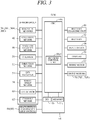
- FIG. 3 is a block diagram showing the configuration of the control apparatus of the utility vehicle according to the present embodiment including an Electronic Control Unit.
- reference symbol 10 designates a utility vehicle, more precisely an autonomously navigating utility vehicle, e.g., a mower; hereinafter called “vehicle”.
- the utility vehicle of the present invention can be embodied in the form of various types of utility vehicle and particularly as an autonomously navigating utility vehicle as a lawn mower for lawn or grass mowing work.
- the forward direction (longitudinal direction) of the utility vehicle in plan view and the vehicle width direction perpendicular to the forward direction are defined as the forward-rearward direction and the leftward-rightward direction, respectively, and the height direction of the utility vehicle is defined as the upward-downward direction.
- the configuration of the constituents is explained in line with these definitions.
- a body 12 of the vehicle 10 comprises a chassis 12a and a frame 12b attached thereto.
- the vehicle 10 is equipped with relatively small diameter left and right front wheels 14 rotatably fastened to a front end of the chassis 12a through stays 12a1 and relatively large diameter left and right rear wheels 16 rotatably fastened to the chassis 12a directly.
- a work unit e.g., a mower blade (rotary blade) 20
- a work motor hereinafter called “work motor” 22
- the blade 20 is connected to the electric motor 22 to be driven to rotate by the electric motor 22.
- a blade height regulation mechanism 24 manually operable by an operator is connected to the blade 20.
- the blade height regulation mechanism 24 is equipped with a screw (not shown) and configured to enable the operator to regulate the height of the blade 20 above ground level GR by manually rotating the screw.
- drive motors 26 Two electric motors (hereinafter called “drive motors") 26 are attached to the chassis 12a of the vehicle 10 at a rear end of the blade 20.
- the drive motors 26 are connected to the left and right rear wheels 16 and rotate normally (drive the vehicle 10 to run forward) or reversely (drive the vehicle 10 to run backward) independently on the left and right, with the front wheels 14 as non-driven (free) wheels and the rear wheels 16 as driven wheels.
- the blade 20, work motor 22, drive motors 26 and so on are covered by the frame 12b.
- the weight and size of the vehicle 1 are such that it can be transported or carried by the operator.
- a vehicle 1 whose total length (forward-rearward direction length) is about 710 mm, total width about 550 mm, and height about 300 mm.
- a battery charging unit 30 and an onboard battery 32 are housed at the rear of the vehicle 10, and a pair of charging terminals 34 are attached to the frame 12b so as to project forward.
- the battery 32 comprises lithium-ion battery, for example.
- the charging terminals 34 are connected to the charging unit 30 through cables, and the charging unit 30 is connected to the battery 32 by cables.
- the work motor 22 and the drive motors 26 are connected to the battery 32 through connecting cables and are supplied with current from the battery 32.
- the cables are not shown in FIG. 1 .
- the vehicle 10 is thus configured as a 4-wheel, electrically-powered, autonomously navigating utility vehicle.
- Left and right magnetic sensors 36 are installed at the front of the body 12 of the vehicle 10 at positions laterally symmetrical with respect to a center line extending in the straight forward direction of the vehicle 10. More specifically, as shown in FIG. 2 , the first and second magnetic sensors 36R and 36L are installed laterally symmetrically with respect to a center line CL running in the straight forward direction along the widthwise center of the vehicle 10. In addition, a third magnetic sensor 36C is installed on the center line CL1 at a location remote from the sensors 36L and 36R. The magnetic sensors 36 produces an output indicating magnitude of magnetic field (magnetic field strength or intensity).
- a collision (contact) sensor 40 is attached to the frame 12b.
- the collision sensor 40 outputs an ON signal when the frame 12b detaches from the chassis 12a owing to collision (contact) with an obstacle or foreign object.
- a housing box (not shown) installed near the middle of the vehicle 10 houses a printed circuit board 42 carrying an ECU (Electronic Control Unit) 44, which comprises a microcomputer having CPU (microprocessor) 44a, I/O 44b, and memory (ROM, RAM, EEPROM, etc.) 44c and the like.
- ECU Electronic Control Unit
- an angular velocity sensor (yaw-rate sensor; yaw sensor) 46 that generates an output indicating angular velocity (yaw-rate) around a center-of-gravity z-axis (vertical axis) of the vehicle 10 (whose time-integrated value indicates a turn angle around the vertical axis)
- a G sensor acceleration sensor
- a direction sensor that generates an output indicating direction (azimuth) of the vehicle 10 according to terrestrial magnetism
- a GPS Global Positioning System
- Wheel speed sensors 56 installed near the rear wheels 16 produce outputs indicating the wheel speeds of the rear wheels 16, and a lift sensor 60 installed between the chassis 12a and the frame 12b outputs an ON signal when the frame 12b is lifted off the chassis 12a by the operator or other worker.
- the vehicle 10 is equipped with a main switch 56 and an emergency stop switch 60 both operable by the operator.
- a current sensor 62 is installed at input/output circuit of the battery 32 and produces an output indicating consumed current of the battery 32.
- a main switch 64 for inputting various commands of the operator, inter alia, start of operation, and an emergency stop switch 66 for inputting command for stopping the vehicle 10 in case of emergency are installed on the vehicle to be manipulatable by the operator.
- the top of the frame 12b of the vehicle 10 has a large cutaway in which an input device 68 for inputting commands of the operator and a display 70 is fitted.
- the input device 68 and display 70 are connected to the ECU 44.
- the display 70 displays working modes and the like in accordance with commands sent from the ECU 44.
- the outputs of the magnetic sensors 36, collision sensor 40, angular velocity sensor 46, etc. are sent to the ECU 44 through the I/O 44b.
- the ECU 44 controls operation of the vehicle 10 by supplying current to the drive motor 26 from the battery 32 and by sending commands thereto through the I/O 44b.
- Output shafts of the drive motors 26L and 26R are connected to rotating shafts of the left and right rear wheels 16, respectively, so as each to independently drive or rotate the left or right rear wheel 16.
- the drive motors 26L and 26R are configured such that they each independently rotates one of the rear wheels 16 normally (drive the vehicle 10 to run straight forward) or reversely (drive the vehicle 10 to run reverse). By establishing a difference between the rotating speeds of the left and right rear wheels 16, the vehicle 10 can be turned to an arbitrary direction.
- the vehicle 10 when the left and right rear wheels 16 are both rotated normally and the rotational speed of the right rear wheel 16 is greater than the rotational speed of the left rear wheel 16, the vehicle 10 turns left at a turning angle ⁇ in accordance with the speed difference. Conversely, when the rotational speed of the left rear wheel 16 is greater than the rotational speed of the right rear wheel 16, the vehicle 10 turns right at a turning angle ⁇ in accordance with the speed difference. When one of the left and right rear wheels 16 is rotated normally and the other reversely both at the same speed, the vehicle 10 turns on the spot (so-called "pivot-turn").
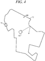
- the vehicle 10 is configured to detect or recognize the working area AR based on the outputs of the aforesaid sensors, in particular the electromagnetic sensors 36 and perform the in the working area AR.
- the working area 70 is delineated by laying (burying) a boundary wire (electrical wire) 72 around its periphery (boundary).
- a charging station 76 for charging the battery 32 of the vehicle 10 is installed above the boundary wire 72 at a location inside or outside, more precisely inside the working AR. The sizes of the vehicle 10 and charging station 76 in FIG. 4 are exaggerated.
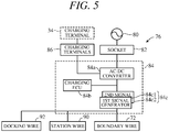
- FIG. 5 is a block diagram showing electrical configuration of the charging station 76
- the charging station 76 is equipped with a charger 84 connected through a socket 82 to a commercial power supply 80, and a pair of charging terminals 86 connected to the charger 84 and connectable to contact contacts 34a (shown in FIG. 2 ) of the pair of charging terminals 34 of the vehicle 10.
- the charger 84 is equipped with an AC-DC converter 84a, a charging ECU (Electronic Control Unit) 84b also comprising a microcomputer and used to control operation of the AC-DC converter 84a, and two signal generators 84c (first signal generator 84c1 and second signal generator 84c2).
- the charging station 76 is configured so that alternating current passing from the commercial power supply 80 through the socket 82 is converted into direct current and is stepped down to a suitable voltage by the AC-DC converter 84a of the charger 84 and sent to the charging terminals 86 to charge the onboard battery 32 through the charging contacts 32 and 86 when the vehicle 10 is returned and connected to the charging station 76.
- the AC-DC converter 84a steps down the current to a suitable voltage in response to commands determined by the ECU 44 and sent from the charging ECU 84b.
- the output of the AC-Dc converter 84 is supplied to the charging ECU 84b and signal generators 84c (comprising a first signal generator 84c1 and a second signal generator 84c2).
- the charging ECU 84b is configured to be capable of communicating with the ECU 44 and controls operation of the first signal generators 84c1 and the second signal generator 84c2 by sending binary data pulses.
- the first and second signal generators 84c1, 84c2 convert the direct current stepped down by the AC-DC converter 84a into area signal in continuance sequence of pulse train and supply the generated area signal to the boundary wire 72, a station wire 90 for delineating the charging station 76a and a docking wire 92 for guiding the vehicle 10 to a charging position.
- FIG. 6 shows the area signal of pulse train generated by the first signal generator 84c1 to be passed through the boundary wire 72 that is corresponding to the binary data pulses sent from the charging ECU 84b.
- the area signal has a signal length L and is supplied to the boundary wire at random periods Tn.
- the second signal generator 84c2 generates similar signal.
- a right-handed magnetic field is generated around the boundary wire 72 (Ampere's right-hand screw rule).
- the magnetic field intensity detected at this time differs depending on the total length of the boundary wire 72 and also differs with distance of the vehicle 10 from the boundary wire 72.
- FIG. 7 is a diagram showing relationship between distance d from the boundary wire 72 and magnetic field strength H. As indicated in FIG. 7 , magnetic field strength H varies with distance d from the boundary wire 72. Specifically, magnetic field strength H is 0 above the boundary wire 2, positive inside the working area AR, and negative outside the same.
- the ECU 44 When work is in progress, the ECU 44 reads outputs of the magnetic sensors 36L, 36R and detects the position of the vehicle 10 in the working area AR. Specifically, the ECU 44 determines whether the vehicle 10 is inside or outside the working area AR and detects distance of the vehicle 10 from the boundary wire 72.
- the ECU 44 reads outputs of the magnetic sensors 36L, 36R and when the outputs are minus, drive the vehicle 10 to turn toward inside the working area AR at a random angle based on, for example, the output of the angular velocity sensor 46.
- work can be carried out inside the working area AR while the vehicle 10 is being driven to run straight forward at random direction, for example.
- the vehicle 10 is controlled to operate in work mode and return mode in response to control commands sent from the ECU 44 in accordance with programs prepared beforehand and memorized in the memory 44c.
- work mode the vehicle 10 works (mows lawn or grass) while autonomously navigating in the working area AR.
- return mode the vehicle 10 is returned to the charging station 76 when the battery 32 requires charging.
- work mode or return mode the vehicle 10 is sometimes controlled to trace along the boundary wire 72. For example, this trace mode is executed before work mode to ascertain the working area AR.
- FIG. 8 is a diagram showing operation of the vehicle 1 in trace mode.
- the vehicle 1 in trace mode the vehicle 1 is driven by commands from the ECU 44 to circuit along the boundary wire 72 with one of the pair of magnetic sensors 36R and 36L (e.g., 36L) positioned inside the boundary wire 72 and so that the other magnetic sensor (e.g., 36R) moves above the boundary wire 72 in the direction of arrow A.
- the ECU 44 monitors output of the magnetic sensor 36R and controls operation of the drive motors 26L and 26R so that magnetic field strength H detected by the magnetic sensor 36R stays at 0.
- Trace mode is started from a state in which the terminals 34 of the vehicle 10 are connected to the terminals 86 of the charging station 76 and ends when the terminals 34 again connect to the terminals 86 after the vehicle 10 makes a circuit along the boundary wire 72. Position of the vehicle 10 from the start to the end of trace mode is successively detected from the output of the GPS receiver 54.
- the ECU 44 Based on the outputs of the GPS receiver 54 and the direction sensor 52, the ECU 44 generates a map of the working area AR (working area map MP) whose origin (starting point) is set at the charging station 76 based on the working area boundary line identified in trace mode.
- working area AR working area map MP
- FIG. 9 is a diagram showing an example of the working area map MP.
- position of the boundary wire 72 is depicted as the boundary line (L0).
- the map MP is configured by arraying the square cells Cmp in a grid pattern within a rectangular coordinate system plane including an X axis and a Y axis (XY plane) corresponding to inside of the working area AR.
- the plane is set with a reference orientation with respect to an origin corresponding to the position of the charging station 76.
- Each cell Cmp includes position data of X, Y coordinate. Size of the cells Cmp can be varied as appropriate and can, for example, be defined to coincide with working width of maximum outer diameter of blade 20.
- the characterizing feature of the control apparatus for a utility vehicle is the turning control of the vehicle 10 in the vicinity of the boundary wire 72, so the following explanation is focused on this point.
- FIG. 10 is a flowchart showing operations of the control apparatus for a utility vehicle.
- the program shown is executed by the CPU 44a of the ECU 44. More exactly, as indicated in FIG. 3 , the ECU 44 has the CPU (microprocessor) 44a and the memory (44c) in which the CPU (microprocessor) 44a is configured to function as a running (operation) control unit (or control means) 44a1, and the processing shown in FIG. 10 is executed by the running control unit 44a1.
- two modes of turning the vehicle 10 are available when it approaches the boundary wire 72, namely a gentle turning mode in which the vehicle 10 is turned while running in the vicinity of the boundary wire 72 (gentle angle turning; first turning mode) and a sharp turning mode in which the vehicle 10 is once paused near the boundary wire 72 and then turned (turning at a sharp angle; second turning mode).
- the mode is switched or selected alternatively each time predetermined conditions are satisfied, and operation of drive motors 22 is controlled to turn the vehicle 10 in accordance with the switched turning mode.
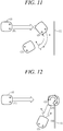
- FIGs. 11 and 12 are explanatory diagrams explaining the gentle turning mode and the sharp turning mode, respectively.
- the vehicle 10 is controlled to run straight ahead (1), turn at a gentle angle without stopping when the magnetic field strength of the boundary wire 72 exceeds a certain value (2), and run straight forward (3).
- Turning radius and turning angle are illustrated in FIG. 14 . Since the position of the vehicle 10 is detected in the working area map MP as stated earlier, approach angle of the vehicle 10 toward the boundary wire 72 is calculated using this map, and the turning angle is calculated to a random value (is arbitrarily defined) between a minimum value and a maximum value (near 180°) from the calculated approach angle and the associated turning radius is calculated to a random value (is arbitrarily defined) between the minimum value and maximum value (near infinity).
- the left and right rear wheels 16 of the utility vehicle 10 can independently be driven forward and rearward, it is possible, as pointed out earlier, to do a so-called "pivot-turn" by rotating one of the rear wheels 16 forward and the other rearward at the same speed to make the vehicle 10 do an about turn (180° turn about) in place.
- sharp turning mode is a mode in which the vehicle 10 is controlled to run straight forward (1), once stop when a front end part of the body 12 corresponding to at least one of the first and second magnetic sensors 36L and 36R crosses over the boundary wire 72 (2), next turn with the front end part of the body 12 that crossed over the boundary wire 72 as the outer wheel side, then stop (4), and thereafter run straight forward (5).
- predetermined conditions include operating time of the vehicle 10. Specifically, it is determined that predetermined conditions are satisfied when the operating time of the vehicle 10 is equal to or greater than a prescribed time and when it is determined that the predetermined operating conditions are satisfied, turning mode is selected (switched).
- the prescribed time defined, for example, as 15 minutes for gentle turning mode and 10 minutes for sharp turning mode.
- the predetermined conditions include the number of turns by the vehicle 10. Specifically it is determined that the predetermined conditions are satisfied when the number of turns by the vehicle 10 is equal to or greater than a prescribed number and when it is determined that the predetermined operating conditions are satisfied, turning mode is switched (selected).
- the prescribed number is defined, for example, as 15 times for gentle turning mode and 10 times for sharp turning mode.
- MODE and COUNT read in S10 of the flowchart of FIG. 10 respectively mean selected turning mode and cumulative total of operating time or number of turns, i.e., the number of times that the predetermined conditions are satisfied.
- S20 it is determined whether COUNT is equal to or greater than X (aforesaid prescribed number of turns or prescribed time).
- the first result in S20 is of course NO and the program goes to S22, in which COUNT is incremented by 1, and then returns to S18.
- the program goes to S24, in which MODE is switched to sharp turning mode (sharp turning mode is selected).
- FIG. 15 is a subroutine flowchart of the gentle turning mode of S18 in the flowchart of FIG. 10 .
- the program returns to S100, and when YES, goes to S104, in which it is determined whether difference value between the outputs of the left and right) magnetic sensors 36L and 36R is equal to or greater than zero, i.e., whether the body 12 is advancing at an approach angle of less than 90° relative to the boundary wire 72 (i.e., obliquely approaching the boundary wire 72).
- the program goes to S108, in which the aforesaid minimum value of the turning radius is calculated, and then to S110, in which the aforesaid minimum value of the turning angle is calculated.
- the (desired) turning radius and (desired) turning angle are calculated, and the vehicle 10 is then turned based on the calculated turning radius and turning angle toward the side of the left or right magnetic sensors 36L or 36R whose output indicates lower magnetic field strength.
- the reason for randomly defining turning range and angle of the vehicle 10 in the processing of S108 to S114 is to avoid running route overlap so as to prevent unmown patches from being left during mowing.
- S116 it is determined whether the actual turning angle is smaller than the desired turning angle calculated in S112, and when the result is NO, the program returns to S114, and when the result in S116 is YES, the program goes to S118, in which it is determined whether the left or right magnetic sensor 36L or 36R, specifically the front right edge of the body 12 where the right sensor 36R is located, crossed over the boundary wire 72 and the right edge of the vehicle 10 went outside the working area AR.
- the program goes to S120, in which the vehicle 10 is once stopped.
- the program goes to S122, in which it is determined whether the front left edge of the vehicle 10 went outside the working area AR based on the outputs of the left and right magnetic sensors 36L and 36R.
- the result of the determination in S122 is NO, and the program goes to S124, in which the utility vehicle 10 is controlled to turn leftward.
- S126 the vehicle 10 is once stopped.
- the program goes to S128, in which the aforesaid minimum value of the turning radius is calculated.
- the program then proceeds from S130 to S138, and so long as the result in S138 remains NO, performs processing similar to that from S108 to S118, thereby achieving right turning by gentle turning.
- the result in S118 is YES and the left edge is determined to be outside the working area AR, so that the result in S122 is YES and the program goes to S140, in which running is controlled so that the vehicle 10 turns right.
- S142 the utility vehicle 10 is once stopped.
- FIG. 16 is a subroutine flowchart of the sharp turning mode of S28.
- S200 the vehicle 10 is driven to run straight forward and the program goes to S202, in which it is determined from the outputs of the left and right magnetic sensors 36L and 36R whether the vehicle 10, more specifically the front of the vehicle 10 (its body 12), is outside the working area.
- the program goes to S208, in which, by processing similar to that of S 108 to S114 of the FIG. 15 flowchart, a desired turn angle is randomly calculated in order to avoid occurrence of unmown patches, and then goes to S210, in which running is controlled so that the vehicle 10 turns left.
- S212 the vehicle 10 is once stopped.
- the present embodiment is configured to have an apparatus and method for controlling operation of a utility vehicle (10) that detects a magnetic field generated during flow of electric current from an electric power supply (signal generators 84c) through a boundary wire (72) laid around a working area (AR) and is driven by a prime mover (drive motor 26) to run within the working area based on the detected magnetic field, comprising: first and second magnetic sensors (36L, 36R) that are installed at lateral right and left positions symmetrical in a vehicle width direction of a body (12) of the utility vehicle (10) with respect to a vehicle center line (CL1) extending in a forward-rearward direction and produce outputs proportional to strength of the magnetic field during flow of electric current through the boundary wire (72); and an electronic control unit (44) having a microprocessor (CPU 44a) and a memory (44c), wherein the microprocessor is configured to function as: a running control unit (44a1, S10 - S36, S100 - S142, S200 - S
- the above configuration enables establishment of first and second turning modes of turning at a gentle angle without pausing near the working area AR and of turning at a sharp angle and by switching turning mode between these modes each time predetermined conditions are satisfied.
- By alternating the turning mode successively it become possible to prevent the problem of leaving an unserviced region in the vicinity of the working area AR, while also enhancing work efficiency.
- the predetermined conditions includes operating time of the vehicle (COUNT), and it is determined that predetermined conditions are satisfied when the operating time of the vehicle (10) is equal to or greater than a prescribed time (X, S20, S30). With this, it becomes possible to switch the turning mode appropriately.
- the predetermined conditions includes number of turn of the vehicle (COUNT), and it is determined that predetermined conditions are satisfied when the number of the turn of the vehicle is equal to or greater than a prescribed number (X, S20, S30). With this, it becomes possible to switch the turning mode appropriately.
- the running control unit memorizes a number of times (COUNT) that the predetermined conditions are satisfied after finishing controlling of the operation of the prime mover (S36).
- the first turning mode is a mode to calculate a turning radius and turning angle of the vehicle (10) and to turn the vehicle (10) in accordance with the calculated turning radius and turning angle toward a side of one of the first and second magnetic sensors (36L, 36R) whose output indicates lower magnetic field strength (S18, S100 - S142).
- approach angle of the vehicle (10) toward the boundary wire (72) is calculated, and the turning radius and turning angle are respectively calculated to random values between minimum values and maximum values from calculated approach angle (S18, S100 - S142). With this, it becomes possible to still more effectively prevent the problem of leaving an unserviced region in the vicinity of the working area AR.
- the second turning angle is a mode to make the vehicle (10) run straight forward, once stop the vehicle (10) when a front end part of the body (12) of the vehicle (10) corresponding to at least one of the first and second magnetic sensors (36L, 36R) crosses over the boundary wire (72), next turn the vehicle (10) with the front end of the body (12) that crossed over the boundary wire (72) as an outer wheel side (S28, S200 - S218).
- an apparatus for controlling operation of a utility vehicle that detects a magnetic field generated during flow of electric current through a boundary wire laid around a working area and is driven to run within the working area based on the detected magnetic field, having left and right magnetic sensor installed at lateral right and left positions of the vehicle to produce outputs proportional to strength of the magnetic field, turning mode is switched between a gentle turning mode to make the vehicle turn while running near the boundary wire and a sharp turning mode to make the vehicle pause near the boundary wire and then turn, when it is determined from the outputs of the magnetic sensors that the vehicle approaches the boundary wire, each time predetermined conditions are satisfied, and operation of the prime mover is controlled such that the vehicle turns in accordance with the switched turning mode (S10 - S36, S100 - S142, S200 - S218).
Landscapes
- Engineering & Computer Science (AREA)
- Transportation (AREA)
- Mechanical Engineering (AREA)
- Power Engineering (AREA)
- Remote Sensing (AREA)
- Physics & Mathematics (AREA)
- Radar, Positioning & Navigation (AREA)
- Life Sciences & Earth Sciences (AREA)
- General Physics & Mathematics (AREA)
- Automation & Control Theory (AREA)
- Aviation & Aerospace Engineering (AREA)
- Combustion & Propulsion (AREA)
- Chemical & Material Sciences (AREA)
- Electromagnetism (AREA)
- Environmental Sciences (AREA)
- Sustainable Development (AREA)
- Sustainable Energy (AREA)
- Geology (AREA)
- General Life Sciences & Earth Sciences (AREA)
- Environmental & Geological Engineering (AREA)
- Control Of Position, Course, Altitude, Or Attitude Of Moving Bodies (AREA)
- Guiding Agricultural Machines (AREA)
- Harvester Elements (AREA)
Abstract
Description
- This invention relates to a control apparatus for a utility vehicle, particularly to a control apparatus for a utility vehicle that is powered by a prime mover and services a working area under running while turning in the vicinity of the working area.
- A prior art control apparatus for a utility vehicle of this type can be found, for example, in European Patent Application Publication No.
2806325 . The control apparatus according to the technology described in the reference is configured so that when the utility vehicle turns in the vicinity of the working area, it turns smoothly without stopping in order to resolve the problem of time being wasted by pausing. - Although work efficiency can be enhanced by turning the utility vehicle in the vicinity of the working area at a gentle angle without pausing in the manner described in the reference, turning at a sharp angle is sometimes necessary to avoid leaving an unserviced region in the vicinity of the working area. However, the reference does not teach two such types of turning.
- Therefore, an object of this invention is to overcome the aforesaid problem by providing a control apparatus for a utility vehicle adapted to turn a utility vehicle in the vicinity of a working area at either a sharp angle or a gentle angle.
- In order to achieve the object, this invention provides an apparatus and method for controlling operation of a utility vehicle that detects a magnetic field generated during flow of electric current through a boundary wire laid around a working area and is driven to run within the working area based on the detected magnetic field, there is provided with left and right magnetic sensor installed at lateral right and left positions of the utility vehicle to produce outputs proportional to strength of the magnetic field. Turning mode is switched between a first turning mode to make the vehicle turn while running near the boundary wire and a second turning mode to make the vehicle pause near the boundary wire and then turn, when it is determined from the outputs of the magnetic sensors that the vehicle approaches the boundary wire, each time predetermined conditions are satisfied, and operation of the prime mover is controlled such that the vehicle turns in accordance with the switched turning modes.
- The above and other objects and advantages will be more apparent from the following description and drawings, in which:
-
FIG. 1 is an overall schematic diagram showing a control apparatus for a utility vehicle according to an embodiment of this invention; -
FIG. 2 is a plan view of the utility vehicle illustrated inFIG. 1 ; -
FIG. 3 is a block diagram showing inputs to an Electronic Control Unit installed in the utility vehicle illustrated inFIG. 1 ; -
FIG. 4 is an explanatory diagram showing a working area (delimited by a boundary wire) of the utility vehicle illustrated inFIG. 1 ; -
FIG. 5 is a block diagram showing configuration of a charging station of the utility vehicle shown inFIG. 4 ; -
FIG. 6 is an explanatory diagram showing data signal of pulse train generated by a signal generator illustrated inFIG. 5 ; -
FIG. 7 is an explanatory diagram showing relationship between distance from the boundary wire and magnetic field strength generated by the data signal ofFIG. 6 ; -
FIG. 8 is an explanatory diagram showing operation in trace mode of the vehicle illustrated inFIG. 1 ; -
FIG. 9 is an explanatory diagram showing an example of a map of the working area illustrated inFIG. 4 ; -
FIG. 10 is a flowchart showing operation of the control apparatus shown inFIG. 1 ; -
FIG. 11 is an explanatory diagram explaining gentle turning mode in the operation illustrated inFIG. 10 ; -
FIG. 12 is an explanatory diagram explaining sharp turning mode in the operation illustrated inFIG. 10 ; -
FIG. 13 is an explanatory diagram explaining the gentle turning mode ofFIG. 11 more specifically; -
FIG. 14 is an explanatory diagram similarly explaining the gentle turning mode ofFIG. 11 more specifically; -
FIG. 15 is a subroutine flowchart of the gentle turning mode ofFIG. 10 ; and -
FIG. 16 is a subroutine flowchart of the sharp turning mode ofFIG. 10 . - A control apparatus for a utility vehicle according to an embodiment of this invention is explained with reference to the attached drawings in the following.
-
FIG. 1 is an overall schematic diagram showing a control apparatus for a utility vehicle according to an embodiment of this invention,FIG. 2 is a plan view schematically illustrating the configuration of the utility vehicle illustrated inFIG. 1 ; andFIG. 3 is a block diagram showing the configuration of the control apparatus of the utility vehicle according to the present embodiment including an Electronic Control Unit. - As shown in
FIG. 1 ,reference symbol 10 designates a utility vehicle, more precisely an autonomously navigating utility vehicle, e.g., a mower; hereinafter called "vehicle". - The utility vehicle of the present invention can be embodied in the form of various types of utility vehicle and particularly as an autonomously navigating utility vehicle as a lawn mower for lawn or grass mowing work. In the following, the forward direction (longitudinal direction) of the utility vehicle in plan view and the vehicle width direction perpendicular to the forward direction are defined as the forward-rearward direction and the leftward-rightward direction, respectively, and the height direction of the utility vehicle is defined as the upward-downward direction. The configuration of the constituents is explained in line with these definitions.
- A
body 12 of thevehicle 10 comprises achassis 12a and aframe 12b attached thereto. Thevehicle 10 is equipped with relatively small diameter left and rightfront wheels 14 rotatably fastened to a front end of thechassis 12a through stays 12a1 and relatively large diameter left and rightrear wheels 16 rotatably fastened to thechassis 12a directly. - A work unit, e.g., a mower blade (rotary blade) 20, is attached near the middle of the
chassis 12a of thevehicle 10, and an electric motor (hereinafter called "work motor") 22 is installed above it. Theblade 20 is connected to theelectric motor 22 to be driven to rotate by theelectric motor 22. - A blade
height regulation mechanism 24 manually operable by an operator is connected to theblade 20. The bladeheight regulation mechanism 24 is equipped with a screw (not shown) and configured to enable the operator to regulate the height of theblade 20 above ground level GR by manually rotating the screw. - Two electric motors (hereinafter called "drive motors") 26 are attached to the
chassis 12a of thevehicle 10 at a rear end of theblade 20. Thedrive motors 26 are connected to the left and rightrear wheels 16 and rotate normally (drive thevehicle 10 to run forward) or reversely (drive thevehicle 10 to run backward) independently on the left and right, with thefront wheels 14 as non-driven (free) wheels and therear wheels 16 as driven wheels. Theblade 20,work motor 22, drivemotors 26 and so on are covered by theframe 12b. - The weight and size of the
vehicle 1 are such that it can be transported or carried by the operator. As an example can be cited avehicle 1 whose total length (forward-rearward direction length) is about 710 mm, total width about 550 mm, and height about 300 mm. - A
battery charging unit 30 and anonboard battery 32 are housed at the rear of thevehicle 10, and a pair ofcharging terminals 34 are attached to theframe 12b so as to project forward. Thebattery 32 comprises lithium-ion battery, for example. - The
charging terminals 34 are connected to thecharging unit 30 through cables, and thecharging unit 30 is connected to thebattery 32 by cables. Thework motor 22 and thedrive motors 26 are connected to thebattery 32 through connecting cables and are supplied with current from thebattery 32. The cables are not shown inFIG. 1 . - The
vehicle 10 is thus configured as a 4-wheel, electrically-powered, autonomously navigating utility vehicle. - Left and right
magnetic sensors 36 are installed at the front of thebody 12 of thevehicle 10 at positions laterally symmetrical with respect to a center line extending in the straight forward direction of thevehicle 10. More specifically, as shown inFIG. 2 , the first and secondmagnetic sensors vehicle 10. In addition, a thirdmagnetic sensor 36C is installed on the center line CL1 at a location remote from thesensors magnetic sensors 36 produces an output indicating magnitude of magnetic field (magnetic field strength or intensity). - A collision (contact)
sensor 40 is attached to theframe 12b. Thecollision sensor 40 outputs an ON signal when theframe 12b detaches from thechassis 12a owing to collision (contact) with an obstacle or foreign object. - A housing box (not shown) installed near the middle of the
vehicle 10 houses a printedcircuit board 42 carrying an ECU (Electronic Control Unit) 44, which comprises a microcomputer having CPU (microprocessor) 44a, I/O 44b, and memory (ROM, RAM, EEPROM, etc.) 44c and the like. - In the vicinity of the
ECU 44 are installed an angular velocity sensor (yaw-rate sensor; yaw sensor) 46 that generates an output indicating angular velocity (yaw-rate) around a center-of-gravity z-axis (vertical axis) of the vehicle 10 (whose time-integrated value indicates a turn angle around the vertical axis), a G sensor (acceleration sensor) 50 that generates an output indicating acceleration G acting on thevehicle 10 in x, y and z (3-axis) directions, adirection sensor 52 that generates an output indicating direction (azimuth) of thevehicle 10 according to terrestrial magnetism, and a GPS (Global Positioning System)receiver 54 that receives satellite-transmitted GPS signals indicating position of the vehicle 10 (theGPS receiver 54 functions as a position sensor that detects position of the vehicle 10). -
Wheel speed sensors 56 installed near therear wheels 16 produce outputs indicating the wheel speeds of therear wheels 16, and alift sensor 60 installed between thechassis 12a and theframe 12b outputs an ON signal when theframe 12b is lifted off thechassis 12a by the operator or other worker. Thevehicle 10 is equipped with amain switch 56 and anemergency stop switch 60 both operable by the operator. Acurrent sensor 62 is installed at input/output circuit of thebattery 32 and produces an output indicating consumed current of thebattery 32. - A
main switch 64 for inputting various commands of the operator, inter alia, start of operation, and anemergency stop switch 66 for inputting command for stopping thevehicle 10 in case of emergency are installed on the vehicle to be manipulatable by the operator. The top of theframe 12b of thevehicle 10 has a large cutaway in which aninput device 68 for inputting commands of the operator and adisplay 70 is fitted. Theinput device 68 anddisplay 70 are connected to theECU 44. Thedisplay 70 displays working modes and the like in accordance with commands sent from the ECU 44. - As shown in
FIG. 3 , the outputs of themagnetic sensors 36,collision sensor 40,angular velocity sensor 46, etc., are sent to theECU 44 through the I/O 44b. Based on the inputted data, theECU 44 controls operation of thevehicle 10 by supplying current to thedrive motor 26 from thebattery 32 and by sending commands thereto through the I/O 44b. - Output shafts of the
drive motors rear wheels 16, respectively, so as each to independently drive or rotate the left or rightrear wheel 16. Thedrive motors rear wheels 16 normally (drive thevehicle 10 to run straight forward) or reversely (drive thevehicle 10 to run reverse). By establishing a difference between the rotating speeds of the left and rightrear wheels 16, thevehicle 10 can be turned to an arbitrary direction. - For example, when the left and right
rear wheels 16 are both rotated normally and the rotational speed of the rightrear wheel 16 is greater than the rotational speed of the leftrear wheel 16, thevehicle 10 turns left at a turning angle θ in accordance with the speed difference. Conversely, when the rotational speed of the leftrear wheel 16 is greater than the rotational speed of the rightrear wheel 16, thevehicle 10 turns right at a turning angle θ in accordance with the speed difference. When one of the left and rightrear wheels 16 is rotated normally and the other reversely both at the same speed, thevehicle 10 turns on the spot (so-called "pivot-turn"). - The
vehicle 10 is configured to detect or recognize the working area AR based on the outputs of the aforesaid sensors, in particular theelectromagnetic sensors 36 and perform the in the working area AR. - The detection of the working area AR and the work thereat will be explained with reference to
FIG. 4 . - The working
area 70 is delineated by laying (burying) a boundary wire (electrical wire) 72 around its periphery (boundary). A chargingstation 76 for charging thebattery 32 of thevehicle 10 is installed above theboundary wire 72 at a location inside or outside, more precisely inside the working AR. The sizes of thevehicle 10 and chargingstation 76 inFIG. 4 are exaggerated. -
FIG. 5 is a block diagram showing electrical configuration of the chargingstation 76; - As shown in
FIG. 5 , the chargingstation 76 is equipped with acharger 84 connected through asocket 82 to acommercial power supply 80, and a pair of chargingterminals 86 connected to thecharger 84 and connectable to contactcontacts 34a (shown inFIG. 2 ) of the pair of chargingterminals 34 of thevehicle 10. - The
charger 84 is equipped with an AC-DC converter 84a, a charging ECU (Electronic Control Unit) 84b also comprising a microcomputer and used to control operation of the AC-DC converter 84a, and twosignal generators 84c (first signal generator 84c1 and second signal generator 84c2). - The charging
station 76 is configured so that alternating current passing from thecommercial power supply 80 through thesocket 82 is converted into direct current and is stepped down to a suitable voltage by the AC-DC converter 84a of thecharger 84 and sent to thecharging terminals 86 to charge theonboard battery 32 through the chargingcontacts vehicle 10 is returned and connected to the chargingstation 76. The AC-DC converter 84a steps down the current to a suitable voltage in response to commands determined by theECU 44 and sent from the chargingECU 84b. - At the same time, the output of the AC-
Dc converter 84 is supplied to the chargingECU 84b andsignal generators 84c (comprising a first signal generator 84c1 and a second signal generator 84c2). The chargingECU 84b is configured to be capable of communicating with theECU 44 and controls operation of the first signal generators 84c1 and the second signal generator 84c2 by sending binary data pulses. - In response thereto, the first and second signal generators 84c1, 84c2 convert the direct current stepped down by the AC-
DC converter 84a into area signal in continuance sequence of pulse train and supply the generated area signal to theboundary wire 72, astation wire 90 for delineating the charging station 76a and adocking wire 92 for guiding thevehicle 10 to a charging position. -
FIG. 6 shows the area signal of pulse train generated by the first signal generator 84c1 to be passed through theboundary wire 72 that is corresponding to the binary data pulses sent from the chargingECU 84b. As shown, the area signal has a signal length L and is supplied to the boundary wire at random periods Tn. Although not shown, the second signal generator 84c2 generates similar signal. - The detection of the working area AR shown in
FIG. 4 will then be explained. - When electric current of the data signal shown in
FIG. 6 is supplied to theboundary wire 72 by the first signal generator 84c1, a right-handed magnetic field is generated around the boundary wire 72 (Ampere's right-hand screw rule). The magnetic field intensity detected at this time differs depending on the total length of theboundary wire 72 and also differs with distance of thevehicle 10 from theboundary wire 72. -
FIG. 7 is a diagram showing relationship between distance d from theboundary wire 72 and magnetic field strength H. As indicated inFIG. 7 , magnetic field strength H varies with distance d from theboundary wire 72. Specifically, magnetic field strength H is 0 above theboundary wire 2, positive inside the working area AR, and negative outside the same. - When work is in progress, the
ECU 44 reads outputs of themagnetic sensors vehicle 10 in the working area AR. Specifically, theECU 44 determines whether thevehicle 10 is inside or outside the working area AR and detects distance of thevehicle 10 from theboundary wire 72. - More specifically, the
ECU 44 reads outputs of themagnetic sensors vehicle 10 to turn toward inside the working area AR at a random angle based on, for example, the output of theangular velocity sensor 46. As a result, work can be carried out inside the working area AR while thevehicle 10 is being driven to run straight forward at random direction, for example. - In the present embodiment, the
vehicle 10 is controlled to operate in work mode and return mode in response to control commands sent from theECU 44 in accordance with programs prepared beforehand and memorized in the memory 44c. In work mode, thevehicle 10 works (mows lawn or grass) while autonomously navigating in the working area AR. In return mode, thevehicle 10 is returned to the chargingstation 76 when thebattery 32 requires charging. In work mode or return mode, thevehicle 10 is sometimes controlled to trace along theboundary wire 72. For example, this trace mode is executed before work mode to ascertain the working area AR. -
FIG. 8 is a diagram showing operation of thevehicle 1 in trace mode. As shown inFIG. 8 , in trace mode thevehicle 1 is driven by commands from theECU 44 to circuit along theboundary wire 72 with one of the pair ofmagnetic sensors boundary wire 72 and so that the other magnetic sensor (e.g., 36R) moves above theboundary wire 72 in the direction of arrow A. Specifically, theECU 44 monitors output of themagnetic sensor 36R and controls operation of thedrive motors magnetic sensor 36R stays at 0. - For example, when magnetic field strength H detected from the output of the
magnetic sensor 36R becomes positive, thevehicle 10 is turned rightward by deceleratingright drive motor 26R and acceleratingleft drive motor 26L. On the other hand, when magnetic field strength H detected from the output of themagnetic sensor 36R becomes negative, thevehicle 10 is turned leftward by accelerating theright drive motor 26R and decelerating theleft drive motor 26L. As a result, the rightmagnetic sensor 36R is brought near theboundary wire 72 and magnetic field strength H detected by the rightmagnetic sensor 36R is maintained at 0, so that thevehicle 10 can run on theboundary wire 72. - Trace mode is started from a state in which the
terminals 34 of thevehicle 10 are connected to theterminals 86 of the chargingstation 76 and ends when theterminals 34 again connect to theterminals 86 after thevehicle 10 makes a circuit along theboundary wire 72. Position of thevehicle 10 from the start to the end of trace mode is successively detected from the output of theGPS receiver 54. - Based on the outputs of the
GPS receiver 54 and thedirection sensor 52, theECU 44 generates a map of the working area AR (working area map MP) whose origin (starting point) is set at the chargingstation 76 based on the working area boundary line identified in trace mode. -
FIG. 9 is a diagram showing an example of the working area map MP. In the map MP, position of theboundary wire 72 is depicted as the boundary line (L0). More specifically, the map MP is configured by arraying the square cells Cmp in a grid pattern within a rectangular coordinate system plane including an X axis and a Y axis (XY plane) corresponding to inside of the working area AR. The plane is set with a reference orientation with respect to an origin corresponding to the position of the chargingstation 76. Each cell Cmp includes position data of X, Y coordinate. Size of the cells Cmp can be varied as appropriate and can, for example, be defined to coincide with working width of maximum outer diameter ofblade 20. - Although the
ECU 44 controls running operation of thevehicle 10 based on the illustrated map MP, the characterizing feature of the control apparatus for a utility vehicle according to this embodiment is the turning control of thevehicle 10 in the vicinity of theboundary wire 72, so the following explanation is focused on this point. -
FIG. 10 is a flowchart showing operations of the control apparatus for a utility vehicle. The program shown is executed by theCPU 44a of theECU 44. More exactly, as indicated inFIG. 3 , theECU 44 has the CPU (microprocessor) 44a and the memory (44c) in which the CPU (microprocessor) 44a is configured to function as a running (operation) control unit (or control means) 44a1, and the processing shown inFIG. 10 is executed by the running control unit 44a1. - Now to explain, when execution of the shown program is commenced by the operator turning ON the
main switch 64, first, in S10, MODE and COUNT (explained later) are read from the EEPROM of the memory 44c. - Next, in S12, it is determined whether the
main switch 64 is OFF, and when the result is NO, the program goes to S14, in which it is determined whether MODE is gentle turning mode. - Here explaining the processing of
FIG. 10 with reference toFIGs. 11 and 12 , in this embodiment two modes of turning thevehicle 10 are available when it approaches theboundary wire 72, namely a gentle turning mode in which thevehicle 10 is turned while running in the vicinity of the boundary wire 72 (gentle angle turning; first turning mode) and a sharp turning mode in which thevehicle 10 is once paused near theboundary wire 72 and then turned (turning at a sharp angle; second turning mode). - During running of the
vehicle 10, the mode is switched or selected alternatively each time predetermined conditions are satisfied, and operation ofdrive motors 22 is controlled to turn thevehicle 10 in accordance with the switched turning mode. -
FIGs. 11 and 12 are explanatory diagrams explaining the gentle turning mode and the sharp turning mode, respectively. - Now for an explanation of the gentle turning mode with reference to
FIG. 11 : In this mode, thevehicle 10 is controlled to run straight ahead (1), turn at a gentle angle without stopping when the magnetic field strength of theboundary wire 72 exceeds a certain value (2), and run straight forward (3). - More specifically, as shown in
FIG. 13 , when the magnetic field strength H of theboundary wire 72 detected by one or the other of the left (first) and right (second)magnetic sensors vehicle 10 are calculated, and thevehicle 10 is turned in accordance with the calculated turning radius and turning angle toward the side of the left or rightmagnetic sensor - Turning radius and turning angle are illustrated in
FIG. 14 . Since the position of thevehicle 10 is detected in the working area map MP as stated earlier, approach angle of thevehicle 10 toward theboundary wire 72 is calculated using this map, and the turning angle is calculated to a random value (is arbitrarily defined) between a minimum value and a maximum value (near 180°) from the calculated approach angle and the associated turning radius is calculated to a random value (is arbitrarily defined) between the minimum value and maximum value (near infinity). - Since the left and right
rear wheels 16 of theutility vehicle 10 can independently be driven forward and rearward, it is possible, as pointed out earlier, to do a so-called "pivot-turn" by rotating one of therear wheels 16 forward and the other rearward at the same speed to make thevehicle 10 do an about turn (180° turn about) in place. - As shown in
FIG. 12 , sharp turning mode is a mode in which thevehicle 10 is controlled to run straight forward (1), once stop when a front end part of thebody 12 corresponding to at least one of the first and secondmagnetic sensors body 12 that crossed over theboundary wire 72 as the outer wheel side, then stop (4), and thereafter run straight forward (5). - In this embodiment, predetermined conditions include operating time of the
vehicle 10. Specifically, it is determined that predetermined conditions are satisfied when the operating time of thevehicle 10 is equal to or greater than a prescribed time and when it is determined that the predetermined operating conditions are satisfied, turning mode is selected (switched). The prescribed time defined, for example, as 15 minutes for gentle turning mode and 10 minutes for sharp turning mode. - Further, the predetermined conditions include the number of turns by the
vehicle 10. Specifically it is determined that the predetermined conditions are satisfied when the number of turns by thevehicle 10 is equal to or greater than a prescribed number and when it is determined that the predetermined operating conditions are satisfied, turning mode is switched (selected). In the case of number of turns, the prescribed number is defined, for example, as 15 times for gentle turning mode and 10 times for sharp turning mode. - MODE and COUNT read in S10 of the flowchart of
FIG. 10 respectively mean selected turning mode and cumulative total of operating time or number of turns, i.e., the number of times that the predetermined conditions are satisfied. - Now returning to the explanation of the flowchart of
FIG. 10 with the foregoing background in mind, when the result in S14 is YES, i.e., when MODE selected in the preceding cycle is determined to be gentle turning mode, the program goes to S16, in which COUNT is reset to zero, and to S18, in which control is performed in accordance with gentle turning mode. This aspect is taken up in further detail later. - Next, in S20, it is determined whether COUNT is equal to or greater than X (aforesaid prescribed number of turns or prescribed time). The first result in S20 is of course NO and the program goes to S22, in which COUNT is incremented by 1, and then returns to S18. On the other hand, when the result in S20 is YES, the program goes to S24, in which MODE is switched to sharp turning mode (sharp turning mode is selected).
- When the result in S14 is NO, i.e., when MODE selected in the preceding cycle is determined to be sharp turning mode, the program goes to S26, in which COUNT is reset to zero, and to S28, in which control is performed in accordance with sharp turning mode. This aspect is also taken up in further detail later below.
- Next, in S30, it is determined whether COUNT is equal to or greater than X, and when the result is NO, the program goes to S32, in which COUNT is incremented by 1, and then returns to S28, and when YES, goes to S34, in which MODE is switched to gentle turning mode (gentle turning mode is selected).
-
FIG. 15 is a subroutine flowchart of the gentle turning mode of S18 in the flowchart ofFIG. 10 . - Now to explain, in S100 the
vehicle 10 is driven to run straight forward, whereafter the program goes to S102, in which it is determined whether a left or right sensor output, i.e., magnetic field strength of the boundary wire detected by one or the other of the left (first) and right (second)magnetic sensors FIG. 13 . - When the result in S102 is NO, the program returns to S100, and when YES, goes to S104, in which it is determined whether difference value between the outputs of the left and right)
magnetic sensors body 12 is advancing at an approach angle of less than 90° relative to the boundary wire 72 (i.e., obliquely approaching the boundary wire 72). - When the result in S104 is NO, the program returns to S100, and when YES, goes to S106, in which it is determined which of the outputs of the left and right
magnetic sensors vehicle 10 is approaching theboundary wire 72 diagonally from the right (and should turn left) or diagonally from the left (and should turn right). - When the
vehicle 10 is determined to be approaching diagonally from the right (and should turn left), the program goes to S108, in which the aforesaid minimum value of the turning radius is calculated, and then to S110, in which the aforesaid minimum value of the turning angle is calculated. - Next, in S112, a desired turning radius and a desired turning angle falling between the minimum values and maximum values of the calculated turning radius and turning angle are randomly calculated from random functions or the like, whereafter the program goes to S114, in which the
vehicle 10 is turned left at the calculated desired turning radius and turning angle. - In other words, when turning in the vicinity of the
boundary wire 72 in gentle turning mode, the (desired) turning radius and (desired) turning angle are calculated, and thevehicle 10 is then turned based on the calculated turning radius and turning angle toward the side of the left or rightmagnetic sensors - The reason for randomly defining turning range and angle of the
vehicle 10 in the processing of S108 to S114 is to avoid running route overlap so as to prevent unmown patches from being left during mowing. - Next, in S116, it is determined whether the actual turning angle is smaller than the desired turning angle calculated in S112, and when the result is NO, the program returns to S114, and when the result in S116 is YES, the program goes to S118, in which it is determined whether the left or right
magnetic sensor body 12 where theright sensor 36R is located, crossed over theboundary wire 72 and the right edge of thevehicle 10 went outside the working area AR. - When the result in S 118 is NO, the program returns to S 114, and gentle turning is achieved by repeating the aforesaid processing.
- On the other hand, when the result in S118 is YES, the program goes to S120, in which the
vehicle 10 is once stopped. In other words, since the situation can be taken to mean that turning could not be completed, the program goes to S122, in which it is determined whether the front left edge of thevehicle 10 went outside the working area AR based on the outputs of the left and rightmagnetic sensors utility vehicle 10 is controlled to turn leftward. Next, in S126, thevehicle 10 is once stopped. - Further, when it is determined in S106 that the
vehicle 10 is approaching theboundary wire 72 diagonally from the left (and should turn right), the program goes to S128, in which the aforesaid minimum value of the turning radius is calculated. The program then proceeds from S130 to S138, and so long as the result in S138 remains NO, performs processing similar to that from S108 to S118, thereby achieving right turning by gentle turning. - On the other hand, when the result in S138 is YES, which can be taken to mean that turning could not be completed, the program goes to S120, in which the
vehicle 10 is once stopped. Next, in S122, whether the front left edge of thevehicle 10 is outside the working area AR is determined based on the outputs of the left and rightmagnetic sensors - In this case, the result in S118 is YES and the left edge is determined to be outside the working area AR, so that the result in S122 is YES and the program goes to S140, in which running is controlled so that the
vehicle 10 turns right. Next, in S142, theutility vehicle 10 is once stopped. -
FIG. 16 is a subroutine flowchart of the sharp turning mode of S28. - Now to explain, in S200 the
vehicle 10 is driven to run straight forward and the program goes to S202, in which it is determined from the outputs of the left and rightmagnetic sensors vehicle 10, more specifically the front of the vehicle 10 (its body 12), is outside the working area. - When the result in S202 is NO, the program returns to S200, and when YES, goes to S204, in which the
vehicle 10 is once stopped. Next, in S206, it is determined whether the left edge of thebody 12 corresponding to the sensor installed region is outside the working area AR from the outputs of the left and rightmagnetic sensors - When the result in S206 is NO, the program goes to S208, in which, by processing similar to that of
S 108 to S114 of theFIG. 15 flowchart, a desired turn angle is randomly calculated in order to avoid occurrence of unmown patches, and then goes to S210, in which running is controlled so that thevehicle 10 turns left. Next, in S212, thevehicle 10 is once stopped. - On the other hand, when the result in S206 is YES, the program goes to S214, in which processing similar to that described regarding S206 is performed, and then to S216, in which running is controlled so that the
vehicle 10 turns right. Next, in S218, thevehicle 10 is once stopped. - Returning to the explanation of the
FIG. 10 flowchart, when, on the other hand, the result of the determination ofS 12 is NO, i.e., when themain switch 64 is determined to be turned OFF, the program goes to S36, in which the values of MODE and COUNT calculated up to that point are stored (entered) in the EEPROM of the memory 44c and the program is terminated. Thus a configuration is adopted in which the number of times that the predetermined conditions are satisfied is memorized in the EEPROM of the memory 44c after finishing controlling of the operation of the drive motors 26 (after stopping work). - As stated above, the present embodiment is configured to have an apparatus and method for controlling operation of a utility vehicle (10) that detects a magnetic field generated during flow of electric current from an electric power supply (signal generators 84c) through a boundary wire (72) laid around a working area (AR) and is driven by a prime mover (drive motor 26) to run within the working area based on the detected magnetic field, comprising: first and second magnetic sensors (36L, 36R) that are installed at lateral right and left positions symmetrical in a vehicle width direction of a body (12) of the utility vehicle (10) with respect to a vehicle center line (CL1) extending in a forward-rearward direction and produce outputs proportional to strength of the magnetic field during flow of electric current through the boundary wire (72); and an electronic control unit (44) having a microprocessor (CPU 44a) and a memory (44c), wherein the microprocessor is configured to function as: a running control unit (44a1, S10 - S36, S100 - S142, S200 - S218) configured to switch turning mode between a first (gentle) turning mode to make the vehicle (10) turn while running near the boundary wire (72) and a second (sharp) turning mode to make the vehicle (10) pause near the boundary wire (72) and then turn, when it is determined from the outputs of the first and second magnetic sensors (36R, 36L) that the vehicle (10) approaches the boundary wire (72), each time predetermined conditions are satisfied, and controls operation of the prime mover (26) such that the vehicle (10) turns in accordance with the switched turning modes.
- The above configuration enables establishment of first and second turning modes of turning at a gentle angle without pausing near the working area AR and of turning at a sharp angle and by switching turning mode between these modes each time predetermined conditions are satisfied. Thus, by alternating the turning mode successively, it become possible to prevent the problem of leaving an unserviced region in the vicinity of the working area AR, while also enhancing work efficiency.
- In the apparatus and method, the predetermined conditions includes operating time of the vehicle (COUNT), and it is determined that predetermined conditions are satisfied when the operating time of the vehicle (10) is equal to or greater than a prescribed time (X, S20, S30). With this, it becomes possible to switch the turning mode appropriately.
- In the apparatus and method, the predetermined conditions includes number of turn of the vehicle (COUNT), and it is determined that predetermined conditions are satisfied when the number of the turn of the vehicle is equal to or greater than a prescribed number (X, S20, S30). With this, it becomes possible to switch the turning mode appropriately.
- In the apparatus and method, the running control unit memorizes a number of times (COUNT) that the predetermined conditions are satisfied after finishing controlling of the operation of the prime mover (S36). With this, in addition to the effects and advantages mentioned above, it becomes possible to switch the turning mode appropriately when resuming the operation.
- In the apparatus and method, the first turning mode is a mode to calculate a turning radius and turning angle of the vehicle (10) and to turn the vehicle (10) in accordance with the calculated turning radius and turning angle toward a side of one of the first and second magnetic sensors (36L, 36R) whose output indicates lower magnetic field strength (S18, S100 - S142). With this, it becomes possible to more effectively prevent the problem of leaving an unserviced region in the vicinity of the working area AR.
- In the apparatus and method, approach angle of the vehicle (10) toward the boundary wire (72) is calculated, and the turning radius and turning angle are respectively calculated to random values between minimum values and maximum values from calculated approach angle (S18, S100 - S142). With this, it becomes possible to still more effectively prevent the problem of leaving an unserviced region in the vicinity of the working area AR.
- In the apparatus and method, the second turning angle is a mode to make the vehicle (10) run straight forward, once stop the vehicle (10) when a front end part of the body (12) of the vehicle (10) corresponding to at least one of the first and second magnetic sensors (36L, 36R) crosses over the boundary wire (72), next turn the vehicle (10) with the front end of the body (12) that crossed over the boundary wire (72) as an outer wheel side (S28, S200 - S218). With this, it becomes possible to more effectively prevent the problem of leaving an unserviced region in the vicinity of the working area AR.
- In the above, it should be noted that values of COUNT and X are examples and should not be limited thereto.
- It should further be noted that although the utility vehicle is applied for a lawn mowing or grass mowing, it may applied to any other type of works.
- In an apparatus for controlling operation of a utility vehicle that detects a magnetic field generated during flow of electric current through a boundary wire laid around a working area and is driven to run within the working area based on the detected magnetic field, having left and right magnetic sensor installed at lateral right and left positions of the vehicle to produce outputs proportional to strength of the magnetic field, turning mode is switched between a gentle turning mode to make the vehicle turn while running near the boundary wire and a sharp turning mode to make the vehicle pause near the boundary wire and then turn, when it is determined from the outputs of the magnetic sensors that the vehicle approaches the boundary wire, each time predetermined conditions are satisfied, and operation of the prime mover is controlled such that the vehicle turns in accordance with the switched turning mode (S10 - S36, S100 - S142, S200 - S218).
Claims (14)
- An apparatus for controlling operation of a utility vehicle (10) that detects a magnetic field generated during flow of electric current from an electric power supply (84c) through a boundary wire (72) laid around a working area and is driven by a prime mover (26) to run within the working area based on the detected magnetic field,
characterized by:first and second magnetic sensors (36L, 36R) that are installed at lateral right and left positions symmetrical in a vehicle width direction of a body (12) of the utility vehicle (10) with respect to a vehicle center line extending in a forward-rearward direction and produce outputs proportional to strength of the magnetic field during flow of electric current through the boundary wire (72); andan electronic control unit (44) having a microprocessor (44a) and a memory (44c),wherein the microprocessor is configured to function as:a running control unit (44c1) configured to switch turning mode between a first turning mode to make the vehicle (10) turn while running near the boundary wire (72) and a second turning mode to make the vehicle (10) pause near the boundary wire (72) and then turn, when it is determined from the outputs of the first and second magnetic sensors (36R, 36L) that the vehicle (10) approaches the boundary wire (72), each time predetermined conditions are satisfied, and controls operation of the prime mover (26) such that the vehicle (10) turns in accordance with the switched turning modes. - The apparatus according to claim 1, wherein the predetermined conditions includes operating time of the vehicle, and it is determined that predetermined conditions are satisfied when the operating time of the vehicle (10) is equal to or greater than a prescribed time (S20, S30).
- The apparatus according to claim 1 or 2, wherein the predetermined conditions includes number of turn of the vehicle, and it is determined that predetermined conditions are satisfied when the number of the turn of the vehicle is equal to or greater than a prescribed number (S20, S30).
- The apparatus according to any of claims 1 to 3, wherein the running control unit memorizes a number of times that the predetermined conditions are satisfied after finishing controlling of the operation of the prime mover (S36).
- The apparatus according to any of claims 1 to 4, wherein the first turning mode is a mode to calculate a turning radius and turning angle of the vehicle (10) and to turn the vehicle (10) in accordance with the calculated turning radius and turning angle toward a side of one of the first and second magnetic sensors (36L, 36R) whose output indicates lower magnetic field strength (S18, S100 - S142).
- The apparatus according to claim 5, wherein approach angle of the vehicle (10) toward the boundary wire (72) is calculated, and the turning radius and turning angle are respectively calculated to random values between minimum values and maximum values from calculated approach angle (S18, S100 - S142).
- The apparatus according to any of claims 1 to 6, wherein the second turning angle is a mode to make the vehicle (10) run straight forward, once stop the vehicle (10) when a front end part of the body (12) of the vehicle (10) corresponding to at least one of the first and second magnetic sensors (36L, 36R) crosses over the boundary wire (72), next turn the vehicle (10) with the front end of the body (12) that crossed over the boundary wire (72) as an outer wheel side (S28, S200 - S218).
- A method for controlling operation of a utility vehicle (10) that detects a magnetic field generated during flow of electric current from an electric power supply (84c) through a boundary wire (72) laid around a working area and is driven by a prime mover (26) to run within the working area based on the detected magnetic field, having:first and second magnetic sensors (36L, 36R) that are installed at lateral right and left positions symmetrical in a vehicle width direction of a body (12) of the utility vehicle (10) with respect to a vehicle center line extending in a forward-rearward direction and produce outputs proportional to strength of the magnetic field during flow of electric current through the boundary wire (72);characterized by the steps of:switching turning mode between a first turning mode to make the vehicle (10) turn while running near the boundary wire (72) and a second turning mode to make the vehicle (10) pause near the boundary wire (72) and then turn, when it is determined from the outputs of the first and second magnetic sensors (36R, 36L) that the vehicle (10) approaches the boundary wire (72), each time predetermined conditions are satisfied, and controlling operation of the prime mover (26) such that the vehicle (10) turns in accordance with the switched turning modes (44c1, S10 - S36, S100 - S142, S200 - S218).
- The method according to claim 8, wherein the predetermined conditions includes operating time of the vehicle, and it is determined that predetermined conditions are satisfied when the operating time of the vehicle (10) is equal to or greater than a prescribed time (S20, S30).
- The method according to claim 8 or 9, wherein the predetermined conditions includes number of turn of the vehicle, and it is determined that predetermined conditions are satisfied when the number of the turn of the vehicle is equal to or greater than a prescribed number (S20, S30).
- The method according to any of claims 8 to 10, wherein the step of turn mode switching memorizes a number of times that the predetermined conditions are satisfied after finishing controlling of the operation of the prime mover (S36).
- The method according to any of claims 8 to 11, wherein the first turning mode is a mode to calculate a turning radius and turning angle of the vehicle (10) and to turn the vehicle (10) in accordance with the calculated turning radius and turning angle toward a side of one of the first and second magnetic sensors (36L, 36R) whose output indicates lower magnetic field strength (S18, S100 - S142).
- The method according to claim 12, wherein approach angle of the vehicle (10) toward the boundary wire (72) is calculated, and the turning radius and turning angle are respectively calculated to random values between minimum values and maximum values from calculated approach angle (S18, S100 - S142).
- The method according to any of claims 8 to 13, wherein the second turning angle is a mode to make the vehicle (10) run straight forward, once stop the vehicle (10) when a front end part of the body (12) of the vehicle (10) corresponding to at least one of the first and second magnetic sensors (36L, 36R) crosses over the boundary wire (72), next turn the vehicle (10) with the front end of the body (12) that crossed over the boundary wire (72) as an outer wheel side (S28, S200 - S218).
Applications Claiming Priority (1)
| Application Number | Priority Date | Filing Date | Title |
|---|---|---|---|
| JP2016071944A JP6498627B2 (en) | 2016-03-31 | 2016-03-31 | Control device for autonomous vehicle |
Publications (2)
| Publication Number | Publication Date |
|---|---|
| EP3225096A1 true EP3225096A1 (en) | 2017-10-04 |
| EP3225096B1 EP3225096B1 (en) | 2020-05-06 |
Family
ID=58464338
Family Applications (1)
| Application Number | Title | Priority Date | Filing Date |
|---|---|---|---|
| EP17164028.7A Active EP3225096B1 (en) | 2016-03-31 | 2017-03-30 | Control apparatus for utility vehicle |
Country Status (3)
| Country | Link |
|---|---|
| US (1) | US10386852B2 (en) |
| EP (1) | EP3225096B1 (en) |
| JP (1) | JP6498627B2 (en) |
Cited By (2)
| Publication number | Priority date | Publication date | Assignee | Title |
|---|---|---|---|---|
| IT202100010295A1 (en) * | 2021-04-22 | 2022-10-22 | Stiga S P A In Breve Anche St S P A | UNIT FOR CONTROLLING, BY PILOT SIGNAL, A SELF-PROPULNED VEHICLE FOR GROUND OR FLOOR MAINTENANCE APPLICATIONS AND ASSOCIATED CONTROL METHOD |
| US12510897B2 (en) | 2022-08-11 | 2025-12-30 | Honda Motor Co., Ltd. | Return node map |
Families Citing this family (12)
| Publication number | Priority date | Publication date | Assignee | Title |
|---|---|---|---|---|
| WO2018000922A1 (en) | 2016-06-30 | 2018-01-04 | Tti (Macao Commercial Offshore) Limited | An autonomous lawn mower and a system for navigating thereof |
| US11172608B2 (en) | 2016-06-30 | 2021-11-16 | Tti (Macao Commercial Offshore) Limited | Autonomous lawn mower and a system for navigating thereof |
| WO2019167207A1 (en) * | 2018-02-28 | 2019-09-06 | 本田技研工業株式会社 | Control device, work machine and program |
| JP7046366B2 (en) * | 2018-08-10 | 2022-04-04 | 和同産業株式会社 | Autonomous control type mower |
| JP2022539936A (en) * | 2019-01-16 | 2022-09-14 | ハイ ロボティクス カンパニー リミテッド | Obstacle avoidance method, device and warehouse robot |
| GB2581956A (en) | 2019-02-20 | 2020-09-09 | Honda Motor Europe Ltd | Utility system and method of charging a utility vehicle |
| JP2020162545A (en) * | 2019-03-29 | 2020-10-08 | 本田技研工業株式会社 | Work machine |
| KR102315678B1 (en) | 2019-07-05 | 2021-10-21 | 엘지전자 주식회사 | Lawn mower robot and control method the same |
| CN112824937B (en) * | 2019-11-20 | 2024-05-28 | 苏州宝时得电动工具有限公司 | Route generation method, device and lawn mower |
| SE544225C2 (en) * | 2020-03-10 | 2022-03-08 | Husqvarna Ab | System and method for navigation of a robotic work tool |
| CN112462787B (en) * | 2020-12-07 | 2023-09-22 | 航天科技控股集团股份有限公司 | Industrial transfer electric transport vehicle control system and control method |
| JP2024139314A (en) * | 2023-03-27 | 2024-10-09 | 三菱重工業株式会社 | Control method, program and mobile object |
Citations (3)
| Publication number | Priority date | Publication date | Assignee | Title |
|---|---|---|---|---|
| EP2703925A1 (en) * | 2011-04-28 | 2014-03-05 | Positec Power Tools (Suzhou) Co., Ltd | Automatic working system, automatic walking device and steering method thereof |
| EP2806325A2 (en) | 2013-04-09 | 2014-11-26 | F. Robotics Acquisitions Ltd. | Domestic robotic system and robot therefor |
| WO2015072897A1 (en) * | 2013-11-12 | 2015-05-21 | Husqvarna Ab | Improved navigation for a robotic working tool |
Family Cites Families (11)
| Publication number | Priority date | Publication date | Assignee | Title |
|---|---|---|---|---|
| JP3493766B2 (en) * | 1994-10-27 | 2004-02-03 | ソニー株式会社 | Playback device |
| JPH09282776A (en) * | 1996-04-15 | 1997-10-31 | Mitsubishi Electric Corp | Disc playback apparatus, playback stop method thereof, and playback restart method thereof |
| JP3479212B2 (en) * | 1998-01-21 | 2003-12-15 | 本田技研工業株式会社 | Control method and device for self-propelled robot |
| JP2002025235A (en) * | 2000-07-07 | 2002-01-25 | Hitachi Ltd | Resume playback method in information playback device |
| ATE510247T1 (en) * | 2001-06-12 | 2011-06-15 | Irobot Corp | METHOD AND SYSTEM FOR MULTI-MODAL COVERING FOR AN AUTONOMOUS ROBOT |
| US7332890B2 (en) | 2004-01-21 | 2008-02-19 | Irobot Corporation | Autonomous robot auto-docking and energy management systems and methods |
| JP4480730B2 (en) * | 2007-01-19 | 2010-06-16 | アイロボット コーポレイション | Autonomous robot docking method |
| JP5828776B2 (en) * | 2012-02-10 | 2015-12-09 | 本田技研工業株式会社 | Control device for unmanned work vehicle |
| JP2015165775A (en) * | 2014-03-03 | 2015-09-24 | 日立工機株式会社 | Self-propelled mower |
| JP5973609B1 (en) * | 2015-03-27 | 2016-08-23 | 本田技研工業株式会社 | Control equipment for unmanned work vehicles |
| CN107291071A (en) * | 2016-03-30 | 2017-10-24 | 苏州宝时得电动工具有限公司 | Automatic working system, automatic running device and its forward method |
-
2016
- 2016-03-31 JP JP2016071944A patent/JP6498627B2/en not_active Expired - Fee Related
-
2017
- 2017-03-29 US US15/473,443 patent/US10386852B2/en active Active
- 2017-03-30 EP EP17164028.7A patent/EP3225096B1/en active Active
Patent Citations (3)
| Publication number | Priority date | Publication date | Assignee | Title |
|---|---|---|---|---|
| EP2703925A1 (en) * | 2011-04-28 | 2014-03-05 | Positec Power Tools (Suzhou) Co., Ltd | Automatic working system, automatic walking device and steering method thereof |
| EP2806325A2 (en) | 2013-04-09 | 2014-11-26 | F. Robotics Acquisitions Ltd. | Domestic robotic system and robot therefor |
| WO2015072897A1 (en) * | 2013-11-12 | 2015-05-21 | Husqvarna Ab | Improved navigation for a robotic working tool |
Cited By (3)
| Publication number | Priority date | Publication date | Assignee | Title |
|---|---|---|---|---|
| IT202100010295A1 (en) * | 2021-04-22 | 2022-10-22 | Stiga S P A In Breve Anche St S P A | UNIT FOR CONTROLLING, BY PILOT SIGNAL, A SELF-PROPULNED VEHICLE FOR GROUND OR FLOOR MAINTENANCE APPLICATIONS AND ASSOCIATED CONTROL METHOD |
| EP4079133A1 (en) * | 2021-04-22 | 2022-10-26 | Stiga S.p.A. in breve anche St. S.p.A. | Unit for controlling a self-propelled vehicle for maintenance operations of a ground or a floor through a guiding system and associated controlling method |
| US12510897B2 (en) | 2022-08-11 | 2025-12-30 | Honda Motor Co., Ltd. | Return node map |
Also Published As
| Publication number | Publication date |
|---|---|
| US20170285652A1 (en) | 2017-10-05 |
| US10386852B2 (en) | 2019-08-20 |
| JP2017182636A (en) | 2017-10-05 |
| JP6498627B2 (en) | 2019-04-10 |
| EP3225096B1 (en) | 2020-05-06 |
Similar Documents
| Publication | Publication Date | Title |
|---|---|---|
| EP3225096B1 (en) | Control apparatus for utility vehicle | |
| EP3232291B1 (en) | Control apparatus for utility robot | |
| EP3741611B1 (en) | Charging station for utility vehicle | |
| EP3226094B1 (en) | Control apparatus for utility vehicle | |
| EP3225094B1 (en) | Control apparatus for utility vehicle | |
| US9876370B2 (en) | Charging station and charging station guide for autonomously navigating utility vehicle | |
| US12419214B2 (en) | Utility vehicle | |
| US9740204B2 (en) | Control apparatus for autonomously navigating utility vehicle | |
| EP3056960B1 (en) | Control apparatus for autonomously navigating utility vehicle | |
| US12072711B2 (en) | Travel route control of autonomous work vehicle using global navigation satellite system | |
| US12510891B2 (en) | Travel route control of autonomous work vehicle to reduce travel distance | |
| US12130633B2 (en) | Travel route control of autonomous work vehicle |
Legal Events
| Date | Code | Title | Description |
|---|---|---|---|
| PUAI | Public reference made under article 153(3) epc to a published international application that has entered the european phase |
Free format text: ORIGINAL CODE: 0009012 |
|
| STAA | Information on the status of an ep patent application or granted ep patent |
Free format text: STATUS: REQUEST FOR EXAMINATION WAS MADE |
|
| 17P | Request for examination filed |
Effective date: 20170330 |
|
| AK | Designated contracting states |
Kind code of ref document: A1 Designated state(s): AL AT BE BG CH CY CZ DE DK EE ES FI FR GB GR HR HU IE IS IT LI LT LU LV MC MK MT NL NO PL PT RO RS SE SI SK SM TR |
|
| AX | Request for extension of the european patent |
Extension state: BA ME |
|
| STAA | Information on the status of an ep patent application or granted ep patent |
Free format text: STATUS: EXAMINATION IS IN PROGRESS |
|
| 17Q | First examination report despatched |
Effective date: 20190320 |
|
| REG | Reference to a national code |
Ref country code: DE Ref legal event code: R079 Ref document number: 602017015982 Country of ref document: DE Free format text: PREVIOUS MAIN CLASS: A01D0034000000 Ipc: B60L0053140000 |
|
| GRAP | Despatch of communication of intention to grant a patent |
Free format text: ORIGINAL CODE: EPIDOSNIGR1 |
|
| STAA | Information on the status of an ep patent application or granted ep patent |
Free format text: STATUS: GRANT OF PATENT IS INTENDED |
|
| RIC1 | Information provided on ipc code assigned before grant |
Ipc: G05D 1/02 20060101ALI20190930BHEP Ipc: B60L 15/20 20060101ALI20190930BHEP Ipc: B60L 53/14 20190101AFI20190930BHEP Ipc: A01D 34/00 20060101ALI20190930BHEP Ipc: B60L 53/36 20190101ALI20190930BHEP |
|
| INTG | Intention to grant announced |
Effective date: 20191104 |
|
| GRAS | Grant fee paid |
Free format text: ORIGINAL CODE: EPIDOSNIGR3 |
|
| GRAA | (expected) grant |
Free format text: ORIGINAL CODE: 0009210 |
|
| STAA | Information on the status of an ep patent application or granted ep patent |
Free format text: STATUS: THE PATENT HAS BEEN GRANTED |
|
| AK | Designated contracting states |
Kind code of ref document: B1 Designated state(s): AL AT BE BG CH CY CZ DE DK EE ES FI FR GB GR HR HU IE IS IT LI LT LU LV MC MK MT NL NO PL PT RO RS SE SI SK SM TR |
|
| REG | Reference to a national code |
Ref country code: GB Ref legal event code: FG4D |
|
| REG | Reference to a national code |
Ref country code: CH Ref legal event code: EP Ref country code: AT Ref legal event code: REF Ref document number: 1266225 Country of ref document: AT Kind code of ref document: T Effective date: 20200515 |
|
| REG | Reference to a national code |
Ref country code: IE Ref legal event code: FG4D |
|
| REG | Reference to a national code |
Ref country code: DE Ref legal event code: R096 Ref document number: 602017015982 Country of ref document: DE |
|
| REG | Reference to a national code |
Ref country code: LT Ref legal event code: MG4D |
|
| REG | Reference to a national code |
Ref country code: NL Ref legal event code: MP Effective date: 20200506 |
|
| PG25 | Lapsed in a contracting state [announced via postgrant information from national office to epo] |
Ref country code: PT Free format text: LAPSE BECAUSE OF FAILURE TO SUBMIT A TRANSLATION OF THE DESCRIPTION OR TO PAY THE FEE WITHIN THE PRESCRIBED TIME-LIMIT Effective date: 20200907 Ref country code: IS Free format text: LAPSE BECAUSE OF FAILURE TO SUBMIT A TRANSLATION OF THE DESCRIPTION OR TO PAY THE FEE WITHIN THE PRESCRIBED TIME-LIMIT Effective date: 20200906 Ref country code: FI Free format text: LAPSE BECAUSE OF FAILURE TO SUBMIT A TRANSLATION OF THE DESCRIPTION OR TO PAY THE FEE WITHIN THE PRESCRIBED TIME-LIMIT Effective date: 20200506 Ref country code: SE Free format text: LAPSE BECAUSE OF FAILURE TO SUBMIT A TRANSLATION OF THE DESCRIPTION OR TO PAY THE FEE WITHIN THE PRESCRIBED TIME-LIMIT Effective date: 20200506 Ref country code: LT Free format text: LAPSE BECAUSE OF FAILURE TO SUBMIT A TRANSLATION OF THE DESCRIPTION OR TO PAY THE FEE WITHIN THE PRESCRIBED TIME-LIMIT Effective date: 20200506 Ref country code: NO Free format text: LAPSE BECAUSE OF FAILURE TO SUBMIT A TRANSLATION OF THE DESCRIPTION OR TO PAY THE FEE WITHIN THE PRESCRIBED TIME-LIMIT Effective date: 20200806 Ref country code: GR Free format text: LAPSE BECAUSE OF FAILURE TO SUBMIT A TRANSLATION OF THE DESCRIPTION OR TO PAY THE FEE WITHIN THE PRESCRIBED TIME-LIMIT Effective date: 20200807 |
|
| PG25 | Lapsed in a contracting state [announced via postgrant information from national office to epo] |
Ref country code: BG Free format text: LAPSE BECAUSE OF FAILURE TO SUBMIT A TRANSLATION OF THE DESCRIPTION OR TO PAY THE FEE WITHIN THE PRESCRIBED TIME-LIMIT Effective date: 20200806 Ref country code: RS Free format text: LAPSE BECAUSE OF FAILURE TO SUBMIT A TRANSLATION OF THE DESCRIPTION OR TO PAY THE FEE WITHIN THE PRESCRIBED TIME-LIMIT Effective date: 20200506 Ref country code: HR Free format text: LAPSE BECAUSE OF FAILURE TO SUBMIT A TRANSLATION OF THE DESCRIPTION OR TO PAY THE FEE WITHIN THE PRESCRIBED TIME-LIMIT Effective date: 20200506 Ref country code: LV Free format text: LAPSE BECAUSE OF FAILURE TO SUBMIT A TRANSLATION OF THE DESCRIPTION OR TO PAY THE FEE WITHIN THE PRESCRIBED TIME-LIMIT Effective date: 20200506 |
|
| REG | Reference to a national code |
Ref country code: AT Ref legal event code: MK05 Ref document number: 1266225 Country of ref document: AT Kind code of ref document: T Effective date: 20200506 |
|
| PG25 | Lapsed in a contracting state [announced via postgrant information from national office to epo] |
Ref country code: AL Free format text: LAPSE BECAUSE OF FAILURE TO SUBMIT A TRANSLATION OF THE DESCRIPTION OR TO PAY THE FEE WITHIN THE PRESCRIBED TIME-LIMIT Effective date: 20200506 Ref country code: NL Free format text: LAPSE BECAUSE OF FAILURE TO SUBMIT A TRANSLATION OF THE DESCRIPTION OR TO PAY THE FEE WITHIN THE PRESCRIBED TIME-LIMIT Effective date: 20200506 |
|
| PG25 | Lapsed in a contracting state [announced via postgrant information from national office to epo] |
Ref country code: AT Free format text: LAPSE BECAUSE OF FAILURE TO SUBMIT A TRANSLATION OF THE DESCRIPTION OR TO PAY THE FEE WITHIN THE PRESCRIBED TIME-LIMIT Effective date: 20200506 Ref country code: DK Free format text: LAPSE BECAUSE OF FAILURE TO SUBMIT A TRANSLATION OF THE DESCRIPTION OR TO PAY THE FEE WITHIN THE PRESCRIBED TIME-LIMIT Effective date: 20200506 Ref country code: EE Free format text: LAPSE BECAUSE OF FAILURE TO SUBMIT A TRANSLATION OF THE DESCRIPTION OR TO PAY THE FEE WITHIN THE PRESCRIBED TIME-LIMIT Effective date: 20200506 Ref country code: SM Free format text: LAPSE BECAUSE OF FAILURE TO SUBMIT A TRANSLATION OF THE DESCRIPTION OR TO PAY THE FEE WITHIN THE PRESCRIBED TIME-LIMIT Effective date: 20200506 Ref country code: ES Free format text: LAPSE BECAUSE OF FAILURE TO SUBMIT A TRANSLATION OF THE DESCRIPTION OR TO PAY THE FEE WITHIN THE PRESCRIBED TIME-LIMIT Effective date: 20200506 Ref country code: RO Free format text: LAPSE BECAUSE OF FAILURE TO SUBMIT A TRANSLATION OF THE DESCRIPTION OR TO PAY THE FEE WITHIN THE PRESCRIBED TIME-LIMIT Effective date: 20200506 Ref country code: CZ Free format text: LAPSE BECAUSE OF FAILURE TO SUBMIT A TRANSLATION OF THE DESCRIPTION OR TO PAY THE FEE WITHIN THE PRESCRIBED TIME-LIMIT Effective date: 20200506 Ref country code: IT Free format text: LAPSE BECAUSE OF FAILURE TO SUBMIT A TRANSLATION OF THE DESCRIPTION OR TO PAY THE FEE WITHIN THE PRESCRIBED TIME-LIMIT Effective date: 20200506 |
|
| REG | Reference to a national code |
Ref country code: DE Ref legal event code: R097 Ref document number: 602017015982 Country of ref document: DE |
|
| PG25 | Lapsed in a contracting state [announced via postgrant information from national office to epo] |
Ref country code: SK Free format text: LAPSE BECAUSE OF FAILURE TO SUBMIT A TRANSLATION OF THE DESCRIPTION OR TO PAY THE FEE WITHIN THE PRESCRIBED TIME-LIMIT Effective date: 20200506 Ref country code: PL Free format text: LAPSE BECAUSE OF FAILURE TO SUBMIT A TRANSLATION OF THE DESCRIPTION OR TO PAY THE FEE WITHIN THE PRESCRIBED TIME-LIMIT Effective date: 20200506 |
|
| PLBE | No opposition filed within time limit |
Free format text: ORIGINAL CODE: 0009261 |
|
| STAA | Information on the status of an ep patent application or granted ep patent |
Free format text: STATUS: NO OPPOSITION FILED WITHIN TIME LIMIT |
|
| 26N | No opposition filed |
Effective date: 20210209 |
|
| PG25 | Lapsed in a contracting state [announced via postgrant information from national office to epo] |
Ref country code: SI Free format text: LAPSE BECAUSE OF FAILURE TO SUBMIT A TRANSLATION OF THE DESCRIPTION OR TO PAY THE FEE WITHIN THE PRESCRIBED TIME-LIMIT Effective date: 20200506 |
|
| REG | Reference to a national code |
Ref country code: DE Ref legal event code: R084 Ref document number: 602017015982 Country of ref document: DE |
|
| PG25 | Lapsed in a contracting state [announced via postgrant information from national office to epo] |
Ref country code: MC Free format text: LAPSE BECAUSE OF FAILURE TO SUBMIT A TRANSLATION OF THE DESCRIPTION OR TO PAY THE FEE WITHIN THE PRESCRIBED TIME-LIMIT Effective date: 20200506 |
|
| REG | Reference to a national code |
Ref country code: CH Ref legal event code: PL |
|
| GBPC | Gb: european patent ceased through non-payment of renewal fee |
Effective date: 20210330 |
|
| REG | Reference to a national code |
Ref country code: BE Ref legal event code: MM Effective date: 20210331 |
|
| PG25 | Lapsed in a contracting state [announced via postgrant information from national office to epo] |
Ref country code: GB Free format text: LAPSE BECAUSE OF NON-PAYMENT OF DUE FEES Effective date: 20210330 Ref country code: IE Free format text: LAPSE BECAUSE OF NON-PAYMENT OF DUE FEES Effective date: 20210330 Ref country code: LU Free format text: LAPSE BECAUSE OF NON-PAYMENT OF DUE FEES Effective date: 20210330 Ref country code: LI Free format text: LAPSE BECAUSE OF NON-PAYMENT OF DUE FEES Effective date: 20210331 Ref country code: CH Free format text: LAPSE BECAUSE OF NON-PAYMENT OF DUE FEES Effective date: 20210331 |
|
| PGFP | Annual fee paid to national office [announced via postgrant information from national office to epo] |
Ref country code: FR Payment date: 20220210 Year of fee payment: 6 |
|
| PG25 | Lapsed in a contracting state [announced via postgrant information from national office to epo] |
Ref country code: BE Free format text: LAPSE BECAUSE OF NON-PAYMENT OF DUE FEES Effective date: 20210331 |
|
| PG25 | Lapsed in a contracting state [announced via postgrant information from national office to epo] |
Ref country code: HU Free format text: LAPSE BECAUSE OF FAILURE TO SUBMIT A TRANSLATION OF THE DESCRIPTION OR TO PAY THE FEE WITHIN THE PRESCRIBED TIME-LIMIT; INVALID AB INITIO Effective date: 20170330 |
|
| PG25 | Lapsed in a contracting state [announced via postgrant information from national office to epo] |
Ref country code: CY Free format text: LAPSE BECAUSE OF FAILURE TO SUBMIT A TRANSLATION OF THE DESCRIPTION OR TO PAY THE FEE WITHIN THE PRESCRIBED TIME-LIMIT Effective date: 20200506 |
|
| PG25 | Lapsed in a contracting state [announced via postgrant information from national office to epo] |
Ref country code: FR Free format text: LAPSE BECAUSE OF NON-PAYMENT OF DUE FEES Effective date: 20230331 |
|
| PG25 | Lapsed in a contracting state [announced via postgrant information from national office to epo] |
Ref country code: MK Free format text: LAPSE BECAUSE OF FAILURE TO SUBMIT A TRANSLATION OF THE DESCRIPTION OR TO PAY THE FEE WITHIN THE PRESCRIBED TIME-LIMIT Effective date: 20200506 |
|
| PG25 | Lapsed in a contracting state [announced via postgrant information from national office to epo] |
Ref country code: MT Free format text: LAPSE BECAUSE OF FAILURE TO SUBMIT A TRANSLATION OF THE DESCRIPTION OR TO PAY THE FEE WITHIN THE PRESCRIBED TIME-LIMIT Effective date: 20200506 |
|
| PG25 | Lapsed in a contracting state [announced via postgrant information from national office to epo] |
Ref country code: TR Free format text: LAPSE BECAUSE OF FAILURE TO SUBMIT A TRANSLATION OF THE DESCRIPTION OR TO PAY THE FEE WITHIN THE PRESCRIBED TIME-LIMIT Effective date: 20200506 |
|
| PGFP | Annual fee paid to national office [announced via postgrant information from national office to epo] |
Ref country code: DE Payment date: 20260219 Year of fee payment: 10 |