EP3223452B1 - Method and apparatus for providing service on basis of identifier of user equipment - Google Patents
Method and apparatus for providing service on basis of identifier of user equipment Download PDFInfo
- Publication number
- EP3223452B1 EP3223452B1 EP15861698.7A EP15861698A EP3223452B1 EP 3223452 B1 EP3223452 B1 EP 3223452B1 EP 15861698 A EP15861698 A EP 15861698A EP 3223452 B1 EP3223452 B1 EP 3223452B1
- Authority
- EP
- European Patent Office
- Prior art keywords
- user
- scanner
- message
- user equipment
- server
- Prior art date
- Legal status (The legal status is an assumption and is not a legal conclusion. Google has not performed a legal analysis and makes no representation as to the accuracy of the status listed.)
- Active
Links
Images






Classifications
-
- H—ELECTRICITY
- H04—ELECTRIC COMMUNICATION TECHNIQUE
- H04L—TRANSMISSION OF DIGITAL INFORMATION, e.g. TELEGRAPHIC COMMUNICATION
- H04L9/00—Cryptographic mechanisms or cryptographic arrangements for secret or secure communications; Network security protocols
- H04L9/32—Cryptographic mechanisms or cryptographic arrangements for secret or secure communications; Network security protocols including means for verifying the identity or authority of a user of the system or for message authentication, e.g. authorization, entity authentication, data integrity or data verification, non-repudiation, key authentication or verification of credentials
- H04L9/3226—Cryptographic mechanisms or cryptographic arrangements for secret or secure communications; Network security protocols including means for verifying the identity or authority of a user of the system or for message authentication, e.g. authorization, entity authentication, data integrity or data verification, non-repudiation, key authentication or verification of credentials using a predetermined code, e.g. password, passphrase or PIN
-
- H—ELECTRICITY
- H04—ELECTRIC COMMUNICATION TECHNIQUE
- H04L—TRANSMISSION OF DIGITAL INFORMATION, e.g. TELEGRAPHIC COMMUNICATION
- H04L63/00—Network architectures or network communication protocols for network security
- H04L63/10—Network architectures or network communication protocols for network security for controlling access to devices or network resources
- H04L63/107—Network architectures or network communication protocols for network security for controlling access to devices or network resources wherein the security policies are location-dependent, e.g. entities privileges depend on current location or allowing specific operations only from locally connected terminals
-
- H—ELECTRICITY
- H04—ELECTRIC COMMUNICATION TECHNIQUE
- H04L—TRANSMISSION OF DIGITAL INFORMATION, e.g. TELEGRAPHIC COMMUNICATION
- H04L9/00—Cryptographic mechanisms or cryptographic arrangements for secret or secure communications; Network security protocols
- H04L9/32—Cryptographic mechanisms or cryptographic arrangements for secret or secure communications; Network security protocols including means for verifying the identity or authority of a user of the system or for message authentication, e.g. authorization, entity authentication, data integrity or data verification, non-repudiation, key authentication or verification of credentials
-
- H—ELECTRICITY
- H04—ELECTRIC COMMUNICATION TECHNIQUE
- H04L—TRANSMISSION OF DIGITAL INFORMATION, e.g. TELEGRAPHIC COMMUNICATION
- H04L9/00—Cryptographic mechanisms or cryptographic arrangements for secret or secure communications; Network security protocols
- H04L9/32—Cryptographic mechanisms or cryptographic arrangements for secret or secure communications; Network security protocols including means for verifying the identity or authority of a user of the system or for message authentication, e.g. authorization, entity authentication, data integrity or data verification, non-repudiation, key authentication or verification of credentials
- H04L9/3226—Cryptographic mechanisms or cryptographic arrangements for secret or secure communications; Network security protocols including means for verifying the identity or authority of a user of the system or for message authentication, e.g. authorization, entity authentication, data integrity or data verification, non-repudiation, key authentication or verification of credentials using a predetermined code, e.g. password, passphrase or PIN
- H04L9/3228—One-time or temporary data, i.e. information which is sent for every authentication or authorization, e.g. one-time-password, one-time-token or one-time-key
-
- H—ELECTRICITY
- H04—ELECTRIC COMMUNICATION TECHNIQUE
- H04W—WIRELESS COMMUNICATION NETWORKS
- H04W12/00—Security arrangements; Authentication; Protecting privacy or anonymity
- H04W12/06—Authentication
-
- H—ELECTRICITY
- H04—ELECTRIC COMMUNICATION TECHNIQUE
- H04W—WIRELESS COMMUNICATION NETWORKS
- H04W4/00—Services specially adapted for wireless communication networks; Facilities therefor
- H04W4/02—Services making use of location information
- H04W4/029—Location-based management or tracking services
-
- H—ELECTRICITY
- H04—ELECTRIC COMMUNICATION TECHNIQUE
- H04W—WIRELESS COMMUNICATION NETWORKS
- H04W4/00—Services specially adapted for wireless communication networks; Facilities therefor
- H04W4/70—Services for machine-to-machine communication [M2M] or machine type communication [MTC]
-
- H—ELECTRICITY
- H04—ELECTRIC COMMUNICATION TECHNIQUE
- H04W—WIRELESS COMMUNICATION NETWORKS
- H04W4/00—Services specially adapted for wireless communication networks; Facilities therefor
- H04W4/80—Services using short range communication, e.g. near-field communication [NFC], radio-frequency identification [RFID] or low energy communication
-
- H—ELECTRICITY
- H04—ELECTRIC COMMUNICATION TECHNIQUE
- H04W—WIRELESS COMMUNICATION NETWORKS
- H04W48/00—Access restriction; Network selection; Access point selection
- H04W48/02—Access restriction performed under specific conditions
- H04W48/04—Access restriction performed under specific conditions based on user or terminal location or mobility data, e.g. moving direction, speed
-
- G—PHYSICS
- G06—COMPUTING OR CALCULATING; COUNTING
- G06F—ELECTRIC DIGITAL DATA PROCESSING
- G06F2221/00—Indexing scheme relating to security arrangements for protecting computers, components thereof, programs or data against unauthorised activity
- G06F2221/21—Indexing scheme relating to G06F21/00 and subgroups addressing additional information or applications relating to security arrangements for protecting computers, components thereof, programs or data against unauthorised activity
- G06F2221/2111—Location-sensitive, e.g. geographical location, GPS
-
- G—PHYSICS
- G06—COMPUTING OR CALCULATING; COUNTING
- G06Q—INFORMATION AND COMMUNICATION TECHNOLOGY [ICT] SPECIALLY ADAPTED FOR ADMINISTRATIVE, COMMERCIAL, FINANCIAL, MANAGERIAL OR SUPERVISORY PURPOSES; SYSTEMS OR METHODS SPECIALLY ADAPTED FOR ADMINISTRATIVE, COMMERCIAL, FINANCIAL, MANAGERIAL OR SUPERVISORY PURPOSES, NOT OTHERWISE PROVIDED FOR
- G06Q20/00—Payment architectures, schemes or protocols
- G06Q20/30—Payment architectures, schemes or protocols characterised by the use of specific devices or networks
- G06Q20/32—Payment architectures, schemes or protocols characterised by the use of specific devices or networks using wireless devices
- G06Q20/322—Aspects of commerce using mobile devices [M-devices]
- G06Q20/3224—Transactions dependent on location of M-devices
-
- H—ELECTRICITY
- H04—ELECTRIC COMMUNICATION TECHNIQUE
- H04W—WIRELESS COMMUNICATION NETWORKS
- H04W12/00—Security arrangements; Authentication; Protecting privacy or anonymity
- H04W12/60—Context-dependent security
- H04W12/63—Location-dependent; Proximity-dependent
-
- H—ELECTRICITY
- H04—ELECTRIC COMMUNICATION TECHNIQUE
- H04W—WIRELESS COMMUNICATION NETWORKS
- H04W4/00—Services specially adapted for wireless communication networks; Facilities therefor
- H04W4/02—Services making use of location information
Definitions
- the present invention relates to a communication system and, more particularly, to a method and apparatus that enable a user equipment to receive a service matching user needs on the basis of an identifier transmitted by the user equipment.
- IoT Internet of Things
- IoE Internet of Everything
- base technologies such as sensing, wired/wireless communication and network infrastructure, service interfacing and security are needed, and technologies interconnecting things such as sensor networks, Machine-to-Machine (M2M) or Machine Type Communication (MTC) are under development.
- M2M Machine-to-Machine
- MTC Machine Type Communication
- IoT In IoT environments, it is possible to provide intelligent Internet technology services, which collect and analyze data created by interconnected things to add new values to human life.
- IoT technology may be applied to various areas such as smart homes, smart buildings, smart cities, smart or connected cars, smart grids, health-care, smart consumer electronics, and advanced medical services.
- authentication refers to verifying the identity of a user or program so as to prevent an illegitimate user from accessing the system.
- a user equipment may transmit a user identity and password to an authentication server, and the authentication server may transmit a confirmation signal indicating successful verification to the user equipment.
- the authentication server may transmit a confirmation signal indicating successful verification to the user equipment.
- a one-time password may be used to overcome such an undesirable situation. That is, user authentication may be performed using a randomly generated one-time password instead of traditional static passwords. For user authentication, a new one-time password may be generated on the basis of time-synchronization between the authentication server and the client providing the password or on the basis of the previous one-time password.
- One-time passwords are frequently used for user authentication in Internet-based transactions and Internet banking. User authentication may also be performed using various other secure schemes.
- US 2013/282438 A1 discloses methods, systems and devices for providing relevant user information to devices within proximity of a user.
- a wireless identity transmitter associated with the user periodically broadcasts messages that include obscured identifiers.
- a proximate proximity broadcast receiver may receive and relay the broadcast messages to a central server which may process the included information. Based on categories related to the proximity broadcast receiver and the user, the central server may identify subsets of stored profile information about the user that are relevant to the proximity broadcast receiver.
- the central server may transmit relevant profile information to devices to assist in activities associated with the proximity broadcast receiver.
- the central server may only transit relevant profile information that is authorized by the user via permissions associated with the profile. Further, the central server may transmit payment authentication profile information for use by point-of-sale devices within proximity of the user.
- US 2007/300070 A1 discloses a method for determining proximity between a first device and a second device, the method comprising providing a first device storing a first device private key, the first device having an associated secure first device certificate storing secured information, the secured information comprising a first device public key corresponding to the first device private key, providing a second device storing a second device private key, the second device having an associated secure second device certificate storing secured information, the secured information comprising a second device public key corresponding to the second device private key, and a second device processing delay, providing a copy of the second device certificate to the first device, establishing a secure authenticated channel between the first device and the second device, sending a proximity challenge from the first device to the second device, the proximity challenge including a numeric challenge value, receiving the proximity challenge at the second device, processing the proximity challenge at the second device to produce the response to the proximity challenge, and sending the response to the proximity challenge from the second device to the first device, receiving the response to the proximity challenge at the first device, and performing the following at the
- an aspect of the present invention is to provide an authentication procedure that can address the above problem and provide a service in a manner customized to individual user's needs.
- a method for a scanner to realize a service based on a user-service mapping model may include: receiving an encrypted user ID from a user equipment having encrypted a user ID into the encrypted user ID; forwarding the encrypted user ID together with a service ID to a server; receiving first information from the server; and transmitting service related information based on the user ID and the first information to the user equipment or a fixed device.
- the encrypted user ID may be decrypted by the server into the user ID.
- a system comprising a server and a scanner capable of realizing a service based on a user-service mapping model.
- the scanner may include: a transceiver to transmit and receive information to and from multiple devices; and a controller to control a process of receiving an encrypted user ID from a user equipment having encrypted a user ID into the encrypted user ID, forwarding the encrypted user ID and a service ID to the server, receiving first information based on the user ID from the server, and transmitting service related information based on the first information to the user equipment or a fixed device.
- the encrypted user ID may be decrypted by the server into the user ID.
- a method and system that enable a user equipment to perform an authentication procedure and receive a service customized to individual user's needs on the basis of an identifier transmitted by the user equipment.
- blocks of a flowchart (or sequence diagram) and a combination of flowcharts may be represented and executed by computer program instructions.
- These computer program instructions may be loaded on a processor of a general purpose computer, special purpose computer or programmable data processing equipment. When the loaded program instructions are executed by the processor, they create a means for carrying out functions described in the flowchart.
- the computer program instructions may be stored in a computer readable memory that is usable in a specialized computer or a programmable data processing equipment, it is also possible to create articles of manufacture that carry out functions described in the flowchart.
- the computer program instructions may be loaded on a computer or a programmable data processing equipment, when executed as processes, they may carry out steps of functions described in the flowchart.
- a block of a flowchart may correspond to a module, a segment or a code containing one or more executable instructions implementing one or more logical functions, or to a part thereof.
- functions described by blocks may be executed in an order different from the listed order. For example, two blocks listed in sequence may be executed at the same time or executed in reverse order.
- unit may refer to a software component or hardware component such as an FPGA or ASIC capable of carrying out a function or an operation.
- unit or the like is not limited to hardware or software.
- a unit or the like may be configured so as to reside in an addressable storage medium or to drive one or more processors.
- Units or the like may refer to software components, object-oriented software components, class components, task components, processes, functions, attributes, procedures, subroutines, program code segments, drivers, firmware, microcode, circuits, data, databases, data structures, tables, arrays or variables.
- a function provided by a component and unit may be a combination of smaller components and units, and may be combined with others to compose large components and units.
- Components and units may be configured to drive a device or one or more processors in a secure multimedia card.
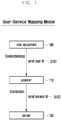
- FIG. 1 illustrates a user-service mapping model forming the basis of the present invention.
- the user equipment 100 transmits a user ID (identification) to the scanner 110 and the scanner 110 identifies the user ID (S101).
- a user equipment is a device or terminal that can be carried and operated by a user.
- a user ID is a unique identifier assigned to a user. Each user may have preference settings including desired service information.
- the user equipment 100 may advertise the user ID at regular intervals without designating a specific receiver, and the scanner 110 may scan the user ID advertised by the user equipment 100.
- the scanner 110 may be fixed at a specific location.
- the user equipment 100 and the scanner 110 are linked to each other through an unsecured wired/wireless connection.
- the link between the user equipment 100 and the scanner 110 may be established through short-range wireless communication such as Bluetooth LE, Wi-Fi (wireless LAN), or Near Field Communication (NFC).
- the scanner 110 Upon scanning the user ID, the scanner 110 transmits the server 120 a service ID of a service available to the user (S102).
- the service ID is a unique identifier assigned to a specific service available to the user.
- the server 120 may verify that the requesting user is a legitimate user by use of a user ID obtained by decrypting the encrypted user ID or information generated using the user ID. If a service available to the user matches the preference settings of the user, the server 120 provides information for providing the service.
- the scanner 110 and the server 120 are linked to each other through a secure wired/wireless connection.
- FIG. 2 illustrates two security attacks that may occur in the user-service mapping model.
- FIG. 2A depicts a replay (playback) attack.
- an attacker 220 may eavesdrop on the communication to intercept the user ID and password (S202).
- the attacker 220 may store the intercepted user ID and password, and, later, transmit the user ID and password to the authentication server 210 on behalf of the user 200 (S203), authenticating the attacker 220.
- Transmitting a user ID through an unsecure connection in the user-service mapping model may be vulnerable to a replay attack. This vulnerability to a replay attack can be addressed by using a different password for each authentication attempt.
- FIG. 2B depicts a man-in-the-middle (MITM) attack.
- MITM man-in-the-middle
- a first device 250 is connected with a second device 260, and this connection is referred to as the original connection 280.
- a third device 270 may establish a new connection 290 by impersonating the second device 260 for the first device 250 and impersonating the first device 250 for the second device 260.
- This is referred to as a man-in-the-middle attack, which may readily occur in long-distance wireless communication.
- automatic user authentication may increase the level of vulnerability to a man-in-the-middle attack.
- it is necessary to apply proximity authentication where, if two connected devices are determined not to be spatially close to each other, the connection therebetween is regarded as an illegitimate connection.
- the distance between two connected devices may be measured using, for example, the round trip time (RTT).
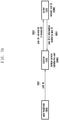
- FIG. 3 illustrates a first embodiment.
- FIG. 3A depicts a simplified configuration of the first embodiment
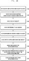
- FIG. 3B is a flowchart describing the first embodiment.
- the user equipment 300 may transmit an encrypted user ID to the scanner 310 (S301).
- the user equipment 300 may advertise the encrypted user ID at regular intervals.
- the scanner 310 may transmit a service ID together with the encrypted user ID to the server 320 (S302).
- the device ID of the scanner 310 may also be transmitted.
- the server 320 may recover the user ID by decrypting the encrypted user ID (S303).
- the server 320 may transmit the user ID or information generated based on the user ID to the scanner 310 (S304). Thereafter, the scanner 310 may initiate a service customized to the user according to the user ID and information related to the user ID (S305).
- the user equipment may advertise a user ID encrypted using a one-time password (OTP) and the scanner may receive the encrypted user ID (330).
- OTP one-time password
- the shared key shared between the server and the user equipment may be associated with the user ID, and the user equipment may generate an encrypted user ID in a time-synchronized manner with the server on the basis of the shared key and a time-based OTP algorithm.
- the encrypted user ID is periodically changed at regular intervals.
- the user ID may be encrypted and transmitted by using various encryption algorithms.
- the scanner may transmit the encrypted user ID and service ID of a service available to the user to the server (340).
- the device ID of the scanner may also be transmitted, and the server may identify the location of the scanner trying to serve the user on the basis of the device ID.
- the server may decrypt the encrypted user ID using the shared key (350).
- the server may verify that the user is a legitimate user on the basis of the decrypted user ID, and, if a service available to the user matches the user preference settings, transmit the user ID and information related to the user ID (generated based on the user ID) to the scanner and an execution device (360).
- the server may encrypt the user ID and information related to the user ID for transmission.
- the server may encrypt the user ID and information related to the user ID by use of a shared key shared with the scanner.
- the corresponding scanner may decrypt the encrypted user ID and information related to the user ID to initiate the service customized to the user. Encryption of information transmitted from the server to the scanner may reduce the risk of exposing the user ID.
- the execution device is a device for providing various services to users, and the scanner may also provide users with various services such as user ID scanning.
- the execution device and the scanner may provide a service customized to the user according to the received user ID (370).
- the user equipment or fixed device may become the target of the service provided by the execution device and the scanner and receive information for providing a service customized to the user.
- the information received by the user equipment or fixed device is directly related to the service provided to the user. For example, in the case of purchase of goods, information directly related to the service may include discount information and partnership coupon information.
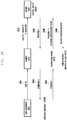
- FIG. 4 illustrates a second embodiment.
- FIG. 4A depicts a simplified configuration of the second embodiment
- FIG. 4B is a flowchart describing the second embodiment.
- the user equipment 400 may transmit an encrypted user ID to the scanner 410 (S401).
- the user equipment 400 may advertise the encrypted user ID at regular intervals.
- the scanner 410 may transmit the encrypted user ID and service ID to the server 420 (S402).
- the device ID of the scanner 410 may also be transmitted.
- the server 420 may recover the user ID by decrypting the encrypted user ID (S403).
- the server 420 may transmit a first challenge to the scanner 410 and the scanner 410 may forward the first challenge to the user equipment 400 (S404).
- the user equipment 400 may generate a first response for the first challenge (S406), and transmit the first response to the scanner 410 (S407).
- the scanner 410 may perform proximity authentication by use of the first response (S407), and transmit the first response and proximity authentication result to the server 420 (S408).
- the server 420 may transmit a service initiation directive to the scanner 410 according to the first response and proximity authentication result.
- the scanner 410 may initiate a service customized to the user (S410).
- the user equipment may advertise a user ID encrypted using an OTP and the scanner may receive the encrypted user ID (430).
- the scanner may transmit the encrypted user ID and service ID of a service available to the user to the server (435).
- the device ID of the scanner may also be transmitted.
- the server may decrypt the encrypted user ID using the shared key (440).
- the server may verify that the user is a legitimate user on the basis of the decrypted user ID, and check whether a service available to the user matches the user preference settings.
- the server may transmit a first challenge to the user equipment (445). This is to use challenge-response authentication where the user computes a value by executing a specific algorithm taking a challenge presented by the server as input and transmits the computed value as a response to the server for authentication.
- the server may share a shared key with the user equipment, generate a random number on the basis of a counter and the shared key, and transmit the random number as a challenge.
- the first challenge may be transmitted to the user equipment via the scanner.
- the user equipment may generate a first response for the first challenge by use of the shared key and transmit the first response to the scanner (450).
- the scanner may perform proximity authentication on the basis of the RTT of the first challenge and first response.
- the first challenge may reach the user equipment before time T0 + x (x ⁇ d/2, d ⁇ 1 ms); and if the user equipment immediately generates a first response and transmits the first response to the scanner, the first response may reach the scanner before time T0 + d. If the first response does not reach the scanner before time T0 + d, it is probable that the user equipment having generated the first response may be a man-in-the-middle attacker other than a legitimate user placed close to the scanner.
- the scanner may determine whether the user having transmitted the first response is a legitimate user on the basis of the arrival time of the first response. If the first response arrives after time T0 + d, the scanner may transmit a lock command to the user equipment having transmitted the first response so that the user equipment is locked. After being locked, the user equipment may request the user to enter a PIN (personal identification number) code. If the user enters a correct PIN code, the user may be again allowed to operate the user equipment.
- PIN personal identification number
- the scanner may transmit the proximity authentication result and first response to the server (460). If it is verified that the user equipment is in a close proximity and the first response corresponds to the first challenge, the server may transmit a service initiation directive to the scanner and the execution device (465).
- the service initiation directive may contain a user ID or a user ID encrypted based on the shared key (shared between the server, the scanner, and the execution device).
- the scanner or execution device may initiate a service customized to the user (470).
- the user equipment or fixed device may become the target of the service provided by the execution device and the scanner and receive information for providing a service customized to the user from the scanner or execution device.
- the information received by the user equipment or fixed device is directly related to the service provided to the user. For example, in the case of purchase of goods, information directly related to the service may include discount information and partnership coupon information.
- the server when the server transmits the first challenge to the scanner, it may also transmit an encrypted first response corresponding to the first challenge.
- the scanner may immediately initiate the service customized to the user. That is, step S409 of FIG. 4A and step 465 of FIG. 4B may be skipped.
- the first response transmitted by the server may be encrypted using a shared key shared between the server and the scanner.
- FIG. 5 illustrates devices for performing proximity authentication.
- the scanner 500 may transmit a first challenge to the user equipment 510 and the user equipment 510 may transmit a first response to the scanner 500, and proximity authentication may be performed using the round trip time.
- Proximity authentication may be performed using various other techniques. For example, to verify proximity, the user equipment may identify the location thereof using a Global Positioning System (GPS) receiver or a Wi-Fi network, and transmit the location information to the scanner. When the user equipment and the scanner each include a sound wave transceiver, the proximity of the user equipment to the scanner may be verified by measuring the round trip time of sound waves.
- GPS Global Positioning System
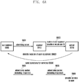
- FIG. 6A illustrates a simplified configuration for providing a service customized to user needs by directly submitting user information to the service provider.
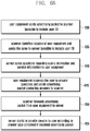
- FIG. 6B is a flowchart of a method for providing a service customized to user needs by directly submitting user information to the service provider.
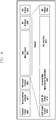
- FIG. 6C is an illustration of an application enabling the user to answer questions presented by the server.
- the user equipment 600 may transmit an advertising packet (S601).
- the advertising packet may contain a user ID (or unique number) identifying the user equipment 600.
- the scanner 610 may identify the location of the user equipment 600 (S602).
- the scanner 610 may transmit location information of the user equipment 600 to the server 620 (S603).
- the user ID may also be transmitted.
- the server 620 may transmit questions for services to the user equipment 600 (S604).
- the user equipment 600 may transmit an advertising packet containing answers to the questions to the scanner 610 and the scanner 610 may forward the advertising packet to the server 620 (S605).
- the server 620 may provide a service to the user according to the answers (S606).
- the user equipment may transmit an advertising packet to the scanner (630).
- the advertising packet may contain a user ID identifying the user equipment.
- the scanner may identify the location of the user equipment using a specific location measurement algorithm. Location measurement may be performed using Time of Arrival (ToA, relationship between the travel time and distance is used) or Received Signal Strength Indication (RSSI, relationship between the signal strength and attenuation during transmission is used).
- the scanner may transmit the identified location information of the user equipment to the server (635).
- the user ID may be transmitted together with the location information.
- the server may transmit questions, which are associated with user information that a service provider in the vicinity of the user equipment wishes to know and are associated with services provided by the service provider, to the user equipment (640).
- the server may transmit the questions via the scanner or directly through a data network to the user equipment.
- the user equipment may request the user to answer the questions and transmit an advertising packet containing the answers to the questions to the scanner (645).
- an advertising packet containing the answers to the questions to the scanner (645).
- the scanner may forward the advertising packet from the user equipment to the server (650).
- the server may provide a service suitable for the user or transmit a service initiation directive to the scanner and the execution device according to the answers contained in the advertising packet (655).
- FIG. 6C is an illustration of an application enabling the user to answer questions presented by the server.
- the questions posed by the server includes one question about an advertisement service 660 (whether to receive a recommendation for advertisement), there questions about a coupon service 670 (whether to receive a specific coupon), and one question about share information management 680 (whether to share user's personal information).
- the user may answer the questions with a YES or NO selection, and the information on the answers may be contained in an advertising packet.
- the specific questions may be rearranged by the server according to the location of the user equipment and may be changed depending on user settings. For example, when the location of the user equipment is identified, the server may arrange the questions so that the most recently used service at the location is selected or the service preferred by many users at the location is selected.
- BLE Bluetooth LE
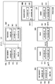
- FIG. 7 illustrates operations of a BLE scan gateway receiving a BLE advertising packet transmitted by the user equipment.
- the user equipment 700 transmits ADV_IND to the BLE scan gateway (720).
- ADV_IND may be used for an advertising event whose recipient connectable through an advertising PDU is not determined (connectable undirected).
- ADV_IND may include the address of the user equipment.
- the BLE scan gateway Upon reception of ADV_IND, the BLE scan gateway transmits SCAN_REQ (730). SCAN_REQ may contain the address of the BLE scan gateway and should be delivered to the user equipment within the time indicated by Time Inter Frame Space (T_IFS).
- T_IFS Time Inter Frame Space
- the user equipment 700 transmits SCAN_RSP to the BLE scan gateway (740).
- SCAN_RSP may include the payload size and carry the payload.
- FIG. 8 illustrates the format of a BLE advertising packet transmitted by the user equipment.
- the BLE advertising packet may include Preamble 800 of 1 byte, Access address 801 of 4 bytes, PDU header 802 of 2 bytes, MAC address 803 of 6 bytes, Advertisement data 804 of up to 31 bytes, and CRC (cyclic redundancy check, 805) of 3 bytes.
- Advertisement data 804 of up to 31 bytes may include a first AD structure composed of Length 810 of 1 byte, AD Type 811 of 1 byte, and Flags 812 of 1 byte, and a second AD structure composed of Length 813 of 1 byte, AD Type 814 of 1 byte, and Manufacturer Specific Data 815 of 25 bytes.
- Manufacturer Specific Data 815 may include Company ID 820 of 2 bytes and User ID 821 of up to 21 bytes.
- the User ID field may be used to store a user ID generated by the OTP algorithm of the first embodiment and the second embodiment.
- the user equipment may generate an advertising packet containing an encrypted user ID and transmit the advertising packet to the scanner.
- FIG. 9 illustrates the format of a BLE data packet transmitted or received.
- the BLE data packet may include Preamble 900 of 1 byte, Access Address 901 of 4 bytes, PDU header 902 of 2 bytes, Data 903 of up to 27 bytes, MIC (Message Integrity Check, 904) of 4 bytes, and CRC 905 of 3 bytes.
- Data 903 may include L2CAP (Logical Link Control and Adaptation Protocol) Length 910 of 2 bytes, L2CAP CID (Channel Identifier) 911 of 2 bytes, Encrypted Manufacturer Specific Data 912, Encrypted Data 913, and MIC 914.
- the user equipment and the scanner may transmit a user ID, challenge, and response by use of BLE data packets.
- FIG. 10 is a block diagram of devices that can provide a service customized to user needs on the basis of the user-service mapping model.
- the user equipment 1000 may include a controller unit 1001, a transceiver unit 1002, and an input unit 1003.
- the controller unit may control the transceiver unit to periodically transmit an advertising packet containing an encrypted user ID.
- the controller unit may control the transceiver unit to receive a challenge from the server 1020 and to transmit a generated response to the scanner 1010.
- the controller unit may control the transceiver unit and the input unit to receive questions from the server, receive answers for the questions from the user, and transmit an advertising packet containing information on the answers to the scanner.
- the scanner 1010 may include a controller unit 1011 and a transceiver unit 1012.
- the controller unit may control the transceiver unit to scan an encrypted user ID transmitted by the user equipment.
- the controller unit may control the transceiver unit to transmit an encrypted user ID, service ID, and device ID to the server, and to receive a user ID and information related to the user ID from the server.
- the controller unit may control the transceiver unit to transmit location information of the user equipment to the server.
- the controller unit may control the transceiver unit to forward a challenge received from the server to the user equipment and to receive a response for the challenge from the user equipment, and may perform RTT computation for proximity authentication.
- the controller unit may control the transceiver unit to transmit a notification message to the server and to receive a service initiation directive from the server.
- the transceiver unit may forward a message received from the server to the user equipment and may forward a message received from the user equipment to the server under the control of the controller unit.
- the transceiver unit may transmit service related information for direct service initiation to the user equipment or the fixed device 1040 under the control of the controller unit.
- the controller unit may provide a service directly to the user according to the service initiation directive or may control the transceiver unit to transmit the service initiation directive or user ID received from the server to the execution device 1030.
- the scanner may be wiredly or wirelessly connected with the user equipment and the server.
- the server 1020 may include a controller unit 1021 and a transceiver unit 1022.
- the controller unit may recover a user ID by decrypting an encrypted user ID using an OTP algorithm, generate information related to the user ID on the basis of the user ID, generate a challenge using a random number, and generate questions for services in consideration of the location of the user equipment.
- the transceiver unit may transmit the user ID, information related to the user ID, and generated challenge to the scanner, and may transmit the questions for services to the user equipment under the control of the controller unit.
- the controller unit may control the transceiver unit to receive a notification message for proximity authentication from the scanner and to transmit a service initiation directive or user ID to the scanner and the execution device 1030.
- the controller unit may provide a service directly to the user if possible.
- the execution device 1030 may include a controller unit 1031 and a transceiver unit 1032.
- the transceiver unit may receive a service initiation directive or user ID from the server or the scanner under the control of the controller unit.
- the controller unit may provide a service to the user if possible.
- the transceiver unit may transmit service related information for direct service initiation to the user equipment or the fixed device under the control of the controller unit.
- the fixed device 1040 may include an output unit 1041, a controller unit 1042, and a transceiver unit 1043.
- the transceiver unit may receive service related information for direct service initiation from the scanner or the execution device under the control of the controller unit.
- the controller unit may control the output unit to output information directly deliverable to the user on the basis of the service related information.
Landscapes
- Engineering & Computer Science (AREA)
- Computer Security & Cryptography (AREA)
- Computer Networks & Wireless Communication (AREA)
- Signal Processing (AREA)
- Computer Hardware Design (AREA)
- Computing Systems (AREA)
- General Engineering & Computer Science (AREA)
- Telephonic Communication Services (AREA)
- Mobile Radio Communication Systems (AREA)
- Information Transfer Between Computers (AREA)
Description
- The present invention relates to a communication system and, more particularly, to a method and apparatus that enable a user equipment to receive a service matching user needs on the basis of an identifier transmitted by the user equipment.
- In recent years, the Internet is evolving from a human centered network where humans create and consume information into the Internet of Things (IoT) where distributed elements or things process and exchange information. Big data processing through cloud servers and IoT technology are being combined into the Internet of Everything (IoE). To realize IoT services, base technologies such as sensing, wired/wireless communication and network infrastructure, service interfacing and security are needed, and technologies interconnecting things such as sensor networks, Machine-to-Machine (M2M) or Machine Type Communication (MTC) are under development.
- In IoT environments, it is possible to provide intelligent Internet technology services, which collect and analyze data created by interconnected things to add new values to human life. Through convergence and combination between existing information technologies and various field technologies, IoT technology may be applied to various areas such as smart homes, smart buildings, smart cities, smart or connected cars, smart grids, health-care, smart consumer electronics, and advanced medical services.
- Meanwhile, as part of efforts to maintain the security of a system or communication network shared by many users, authentication refers to verifying the identity of a user or program so as to prevent an illegitimate user from accessing the system. For authentication, a user equipment may transmit a user identity and password to an authentication server, and the authentication server may transmit a confirmation signal indicating successful verification to the user equipment. When a user transmits the user identity and password through an unsecured connection, there is a risk that someone eavesdrops on the information being transmitted.
- A one-time password (OTP) may be used to overcome such an undesirable situation. That is, user authentication may be performed using a randomly generated one-time password instead of traditional static passwords. For user authentication, a new one-time password may be generated on the basis of time-synchronization between the authentication server and the client providing the password or on the basis of the previous one-time password. One-time passwords are frequently used for user authentication in Internet-based transactions and Internet banking. User authentication may also be performed using various other secure schemes.
-
US 2013/282438 A1 discloses methods, systems and devices for providing relevant user information to devices within proximity of a user. A wireless identity transmitter associated with the user periodically broadcasts messages that include obscured identifiers. A proximate proximity broadcast receiver may receive and relay the broadcast messages to a central server which may process the included information. Based on categories related to the proximity broadcast receiver and the user, the central server may identify subsets of stored profile information about the user that are relevant to the proximity broadcast receiver. The central server may transmit relevant profile information to devices to assist in activities associated with the proximity broadcast receiver. In an embodiment, the central server may only transit relevant profile information that is authorized by the user via permissions associated with the profile. Further, the central server may transmit payment authentication profile information for use by point-of-sale devices within proximity of the user. -
US 2007/300070 A1 discloses a method for determining proximity between a first device and a second device, the method comprising providing a first device storing a first device private key, the first device having an associated secure first device certificate storing secured information, the secured information comprising a first device public key corresponding to the first device private key, providing a second device storing a second device private key, the second device having an associated secure second device certificate storing secured information, the secured information comprising a second device public key corresponding to the second device private key, and a second device processing delay, providing a copy of the second device certificate to the first device, establishing a secure authenticated channel between the first device and the second device, sending a proximity challenge from the first device to the second device, the proximity challenge including a numeric challenge value, receiving the proximity challenge at the second device, processing the proximity challenge at the second device to produce the response to the proximity challenge, and sending the response to the proximity challenge from the second device to the first device, receiving the response to the proximity challenge at the first device, and performing the following at the first device verifying, at the first device, that the response to the proximity challenge is legitimate, determining a gross time between sending the proximity challenge and receiving the response to the proximity challenge, subtracting the second device processing delay from the gross time to produce a net response time, and comparing the net response time to a first threshold and determining whether the first device and the second device are in proximity based on a result of the comparing. - However, when a user equipment transmits the user identity and password through unsecured wireless communication while authentication is automatically performed, a potential intruder who manages to obtain the transmitted information may perform the authentication procedure on behalf of the genuine user. Accordingly, an aspect of the present invention is to provide an authentication procedure that can address the above problem and provide a service in a manner customized to individual user's needs.
- The invention is defined by the appended independent claims.
- In accordance with an aspect of the present invention, there is provided a method for a scanner to realize a service based on a user-service mapping model. The method may include: receiving an encrypted user ID from a user equipment having encrypted a user ID into the encrypted user ID; forwarding the encrypted user ID together with a service ID to a server; receiving first information from the server; and transmitting service related information based on the user ID and the first information to the user equipment or a fixed device. The encrypted user ID may be decrypted by the server into the user ID.
- In accordance with another aspect of the present invention, there is provided a system comprising a server and a scanner capable of realizing a service based on a user-service mapping model. The scanner may include: a transceiver to transmit and receive information to and from multiple devices; and a controller to control a process of receiving an encrypted user ID from a user equipment having encrypted a user ID into the encrypted user ID, forwarding the encrypted user ID and a service ID to the server, receiving first information based on the user ID from the server, and transmitting service related information based on the first information to the user equipment or a fixed device. The encrypted user ID may be decrypted by the server into the user ID.
- In a feature of the present invention, there are provided a method and system that enable a user equipment to perform an authentication procedure and receive a service customized to individual user's needs on the basis of an identifier transmitted by the user equipment.
-
-
FIG. 1 illustrates a user-service mapping model forming the basis of the present invention. -
FIG. 2A depicts a replay (playback) attack that may occur in the user-service mapping model. -
FIG. 2B depicts a man-in-the-middle (MITM) attack that may occur in the user-service mapping model. -
FIG. 3A illustrates a simplified configuration of a first embodiment. -
FIG. 3B is a flowchart describing the first embodiment. -
FIG. 4A illustrates a simplified configuration of a second embodiment. -
FIG. 4B is a flowchart describing the second embodiment. -
FIG. 5 illustrates devices for performing proximity authentication. -
FIG. 6A illustrates a simplified configuration for providing a service customized to user needs by directly submitting user information to the service provider. -
FIG. 6B is a flowchart of a method for providing a service customized to user needs by directly submitting user information to the service provider. -
FIG. 6C is an illustration of an application enabling the user to answer questions presented by a server. -
FIG. 7 illustrates operations of a Bluetooth LE (BLE) scan gateway receiving an advertising packet transmitted by the user equipment using BLE. -
FIG. 8 illustrates the format of a BLE advertising packet transmitted by the user equipment. -
FIG. 9 illustrates the format of a BLE data packet transmitted or received. -
FIG. 10 is a block diagram of devices that can provide a service customized to user needs on the basis of the user-service mapping model. - Hereinafter, embodiments of the present invention are described in detail with reference to the accompanying drawings. Detailed descriptions of well-known functions and structures incorporated herein may be omitted to avoid obscuring the subject matter of the present invention. Particular terms may be defined to describe the invention in the best manner. Accordingly, the meaning of specific terms or words used in the specification and the claims should be construed in accordance with the invention.
- The following description of embodiments of the present invention is focused on wireless communication systems based on Bluetooth Low Energy (BLE). However, it should be understood by those skilled in the art that the subject matter of the present invention is applicable to other communication systems having similar technical backgrounds and channel configurations without significant modifications departing from the scope of the present invention.
- The aspects, features and advantages of certain embodiments of the present invention will be more apparent from the following detailed description taken in conjunction with the accompanying drawings. The description of the various embodiments is to be construed as exemplary only and does not describe every possible instance of the present invention. It should be apparent to those skilled in the art that the following description of various embodiments of the present invention is provided for illustration purpose only and not for the purpose of limiting the present invention as defined by the appended claims and their equivalents. The same reference symbols are used throughout the description to refer to the same parts.
- Meanwhile, it is known to those skilled in the art that blocks of a flowchart (or sequence diagram) and a combination of flowcharts may be represented and executed by computer program instructions. These computer program instructions may be loaded on a processor of a general purpose computer, special purpose computer or programmable data processing equipment. When the loaded program instructions are executed by the processor, they create a means for carrying out functions described in the flowchart. As the computer program instructions may be stored in a computer readable memory that is usable in a specialized computer or a programmable data processing equipment, it is also possible to create articles of manufacture that carry out functions described in the flowchart. As the computer program instructions may be loaded on a computer or a programmable data processing equipment, when executed as processes, they may carry out steps of functions described in the flowchart.
- A block of a flowchart may correspond to a module, a segment or a code containing one or more executable instructions implementing one or more logical functions, or to a part thereof. In some cases, functions described by blocks may be executed in an order different from the listed order. For example, two blocks listed in sequence may be executed at the same time or executed in reverse order.
- In the description, the word "unit", "module" or the like may refer to a software component or hardware component such as an FPGA or ASIC capable of carrying out a function or an operation. However, "unit" or the like is not limited to hardware or software. A unit or the like may be configured so as to reside in an addressable storage medium or to drive one or more processors. Units or the like may refer to software components, object-oriented software components, class components, task components, processes, functions, attributes, procedures, subroutines, program code segments, drivers, firmware, microcode, circuits, data, databases, data structures, tables, arrays or variables. A function provided by a component and unit may be a combination of smaller components and units, and may be combined with others to compose large components and units. Components and units may be configured to drive a device or one or more processors in a secure multimedia card.
-
FIG. 1 illustrates a user-service mapping model forming the basis of the present invention. - Referring to
FIG. 1 , theuser equipment 100 transmits a user ID (identification) to thescanner 110 and thescanner 110 identifies the user ID (S101). A user equipment is a device or terminal that can be carried and operated by a user. A user ID is a unique identifier assigned to a user. Each user may have preference settings including desired service information. At this step, theuser equipment 100 may advertise the user ID at regular intervals without designating a specific receiver, and thescanner 110 may scan the user ID advertised by theuser equipment 100. Thescanner 110 may be fixed at a specific location. Theuser equipment 100 and thescanner 110 are linked to each other through an unsecured wired/wireless connection. The link between theuser equipment 100 and thescanner 110 may be established through short-range wireless communication such as Bluetooth LE, Wi-Fi (wireless LAN), or Near Field Communication (NFC). Upon scanning the user ID, thescanner 110 transmits the server 120 a service ID of a service available to the user (S102). The service ID is a unique identifier assigned to a specific service available to the user. Theserver 120 may verify that the requesting user is a legitimate user by use of a user ID obtained by decrypting the encrypted user ID or information generated using the user ID. If a service available to the user matches the preference settings of the user, theserver 120 provides information for providing the service. Thescanner 110 and theserver 120 are linked to each other through a secure wired/wireless connection. -
FIG. 2 illustrates two security attacks that may occur in the user-service mapping model. -
FIG. 2A depicts a replay (playback) attack. - When a
user 200 transmits a user ID and password to the authentication server 210 (S201), anattacker 220 may eavesdrop on the communication to intercept the user ID and password (S202). Theattacker 220 may store the intercepted user ID and password, and, later, transmit the user ID and password to theauthentication server 210 on behalf of the user 200 (S203), authenticating theattacker 220. Transmitting a user ID through an unsecure connection in the user-service mapping model may be vulnerable to a replay attack. This vulnerability to a replay attack can be addressed by using a different password for each authentication attempt. -
FIG. 2B depicts a man-in-the-middle (MITM) attack. - In
FIG. 2B , afirst device 250 is connected with asecond device 260, and this connection is referred to as theoriginal connection 280. At this time, athird device 270 may establish anew connection 290 by impersonating thesecond device 260 for thefirst device 250 and impersonating thefirst device 250 for thesecond device 260. This is referred to as a man-in-the-middle attack, which may readily occur in long-distance wireless communication. In particular, automatic user authentication may increase the level of vulnerability to a man-in-the-middle attack. To address this problem, it is necessary to apply proximity authentication where, if two connected devices are determined not to be spatially close to each other, the connection therebetween is regarded as an illegitimate connection. Here, the distance between two connected devices may be measured using, for example, the round trip time (RTT). - Next, a description is given of a scheme that provides a service customized to user needs while resolving security problems caused by a replay attack and a man-in-the-middle attack.
-
FIG. 3 illustrates a first embodiment.FIG. 3A depicts a simplified configuration of the first embodiment, andFIG. 3B is a flowchart describing the first embodiment. - Referring to
FIG. 3A , theuser equipment 300 may transmit an encrypted user ID to the scanner 310 (S301). At this step, theuser equipment 300 may advertise the encrypted user ID at regular intervals. Thescanner 310 may transmit a service ID together with the encrypted user ID to the server 320 (S302). Here, the device ID of thescanner 310 may also be transmitted. Theserver 320 may recover the user ID by decrypting the encrypted user ID (S303). Theserver 320 may transmit the user ID or information generated based on the user ID to the scanner 310 (S304). Thereafter, thescanner 310 may initiate a service customized to the user according to the user ID and information related to the user ID (S305). - Referring to
FIG. 3B , in the first embodiment, the user equipment may advertise a user ID encrypted using a one-time password (OTP) and the scanner may receive the encrypted user ID (330). The shared key shared between the server and the user equipment may be associated with the user ID, and the user equipment may generate an encrypted user ID in a time-synchronized manner with the server on the basis of the shared key and a time-based OTP algorithm. In this case, the encrypted user ID is periodically changed at regular intervals. Hence, although an attacker intercepts the encrypted user ID being transmitted, as the encrypted user ID is continuously changed in a time-synchronized manner, the attacker cannot use the intercepted information for being authenticated as the user at the server. Here, the user ID may be encrypted and transmitted by using various encryption algorithms. - Upon reception of the encrypted user ID, the scanner may transmit the encrypted user ID and service ID of a service available to the user to the server (340). Here, the device ID of the scanner may also be transmitted, and the server may identify the location of the scanner trying to serve the user on the basis of the device ID. The server may decrypt the encrypted user ID using the shared key (350). The server may verify that the user is a legitimate user on the basis of the decrypted user ID, and, if a service available to the user matches the user preference settings, transmit the user ID and information related to the user ID (generated based on the user ID) to the scanner and an execution device (360). Here, the server may encrypt the user ID and information related to the user ID for transmission. The server may encrypt the user ID and information related to the user ID by use of a shared key shared with the scanner. The corresponding scanner may decrypt the encrypted user ID and information related to the user ID to initiate the service customized to the user. Encryption of information transmitted from the server to the scanner may reduce the risk of exposing the user ID.
- The execution device is a device for providing various services to users, and the scanner may also provide users with various services such as user ID scanning. The execution device and the scanner may provide a service customized to the user according to the received user ID (370). The user equipment or fixed device may become the target of the service provided by the execution device and the scanner and receive information for providing a service customized to the user. The information received by the user equipment or fixed device is directly related to the service provided to the user. For example, in the case of purchase of goods, information directly related to the service may include discount information and partnership coupon information.
-
FIG. 4 illustrates a second embodiment.FIG. 4A depicts a simplified configuration of the second embodiment, andFIG. 4B is a flowchart describing the second embodiment. - Referring to
FIG. 4A , theuser equipment 400 may transmit an encrypted user ID to the scanner 410 (S401). At this step, theuser equipment 400 may advertise the encrypted user ID at regular intervals. Thescanner 410 may transmit the encrypted user ID and service ID to the server 420 (S402). Here, the device ID of thescanner 410 may also be transmitted. Theserver 420 may recover the user ID by decrypting the encrypted user ID (S403). Theserver 420 may transmit a first challenge to thescanner 410 and thescanner 410 may forward the first challenge to the user equipment 400 (S404). Theuser equipment 400 may generate a first response for the first challenge (S406), and transmit the first response to the scanner 410 (S407). Thescanner 410 may perform proximity authentication by use of the first response (S407), and transmit the first response and proximity authentication result to the server 420 (S408). Theserver 420 may transmit a service initiation directive to thescanner 410 according to the first response and proximity authentication result. Thescanner 410 may initiate a service customized to the user (S410). - Referring to
FIG. 4B , in the second embodiment, the user equipment may advertise a user ID encrypted using an OTP and the scanner may receive the encrypted user ID (430). Upon reception of the encrypted user ID, the scanner may transmit the encrypted user ID and service ID of a service available to the user to the server (435). Here, the device ID of the scanner may also be transmitted. The server may decrypt the encrypted user ID using the shared key (440). The server may verify that the user is a legitimate user on the basis of the decrypted user ID, and check whether a service available to the user matches the user preference settings. These steps are identical to those of the first embodiment. - The server may transmit a first challenge to the user equipment (445). This is to use challenge-response authentication where the user computes a value by executing a specific algorithm taking a challenge presented by the server as input and transmits the computed value as a response to the server for authentication. The server may share a shared key with the user equipment, generate a random number on the basis of a counter and the shared key, and transmit the random number as a challenge. The first challenge may be transmitted to the user equipment via the scanner. Upon reception of the first challenge, the user equipment may generate a first response for the first challenge by use of the shared key and transmit the first response to the scanner (450).
- The scanner may perform proximity authentication on the basis of the RTT of the first challenge and first response. In the case where the user equipment is placed close to the scanner, assuming that the scanner transmits the first challenge at time T0, the first challenge may reach the user equipment before time T0 + x (x < d/2, d ≤ 1 ms); and if the user equipment immediately generates a first response and transmits the first response to the scanner, the first response may reach the scanner before time T0 + d. If the first response does not reach the scanner before time T0 + d, it is probable that the user equipment having generated the first response may be a man-in-the-middle attacker other than a legitimate user placed close to the scanner. The scanner may determine whether the user having transmitted the first response is a legitimate user on the basis of the arrival time of the first response. If the first response arrives after time T0 + d, the scanner may transmit a lock command to the user equipment having transmitted the first response so that the user equipment is locked. After being locked, the user equipment may request the user to enter a PIN (personal identification number) code. If the user enters a correct PIN code, the user may be again allowed to operate the user equipment.
- Upon completion of proximity authentication, the scanner may transmit the proximity authentication result and first response to the server (460). If it is verified that the user equipment is in a close proximity and the first response corresponds to the first challenge, the server may transmit a service initiation directive to the scanner and the execution device (465). The service initiation directive may contain a user ID or a user ID encrypted based on the shared key (shared between the server, the scanner, and the execution device). Upon reception of the service initiation directive, the scanner or execution device may initiate a service customized to the user (470). The user equipment or fixed device may become the target of the service provided by the execution device and the scanner and receive information for providing a service customized to the user from the scanner or execution device. The information received by the user equipment or fixed device is directly related to the service provided to the user. For example, in the case of purchase of goods, information directly related to the service may include discount information and partnership coupon information.
- Alternatively, when the server transmits the first challenge to the scanner, it may also transmit an encrypted first response corresponding to the first challenge. In this case, as the scanner can directly verify the validity of the first response from the user equipment and proximity of the user equipment, the scanner may immediately initiate the service customized to the user. That is, step S409 of
FIG. 4A and step 465 ofFIG. 4B may be skipped. Here, the first response transmitted by the server may be encrypted using a shared key shared between the server and the scanner. -
FIG. 5 illustrates devices for performing proximity authentication. Thescanner 500 may transmit a first challenge to theuser equipment 510 and theuser equipment 510 may transmit a first response to thescanner 500, and proximity authentication may be performed using the round trip time. Proximity authentication may be performed using various other techniques. For example, to verify proximity, the user equipment may identify the location thereof using a Global Positioning System (GPS) receiver or a Wi-Fi network, and transmit the location information to the scanner. When the user equipment and the scanner each include a sound wave transceiver, the proximity of the user equipment to the scanner may be verified by measuring the round trip time of sound waves. - Next, a description is given of a scheme that permits the user to directly transmit user information to the service provider to thereby provide a service customized to user needs on the basis of the location of the user and the user-service mapping model.
-
FIG. 6A illustrates a simplified configuration for providing a service customized to user needs by directly submitting user information to the service provider.FIG. 6B is a flowchart of a method for providing a service customized to user needs by directly submitting user information to the service provider.FIG. 6C is an illustration of an application enabling the user to answer questions presented by the server. - Referring to
FIG. 6A , the user equipment 600 may transmit an advertising packet (S601). Here, the advertising packet may contain a user ID (or unique number) identifying the user equipment 600. Upon reception of the advertising packet, thescanner 610 may identify the location of the user equipment 600 (S602). Thescanner 610 may transmit location information of the user equipment 600 to the server 620 (S603). Here, the user ID may also be transmitted. Theserver 620 may transmit questions for services to the user equipment 600 (S604). The user equipment 600 may transmit an advertising packet containing answers to the questions to thescanner 610 and thescanner 610 may forward the advertising packet to the server 620 (S605). Theserver 620 may provide a service to the user according to the answers (S606). - Referring to
FIG. 6B , the user equipment may transmit an advertising packet to the scanner (630). Here, the advertising packet may contain a user ID identifying the user equipment. Upon reception of the advertising packet, the scanner may identify the location of the user equipment using a specific location measurement algorithm. Location measurement may be performed using Time of Arrival (ToA, relationship between the travel time and distance is used) or Received Signal Strength Indication (RSSI, relationship between the signal strength and attenuation during transmission is used). The scanner may transmit the identified location information of the user equipment to the server (635). Here, the user ID may be transmitted together with the location information. - Upon reception of the location information of the user equipment, the server may transmit questions, which are associated with user information that a service provider in the vicinity of the user equipment wishes to know and are associated with services provided by the service provider, to the user equipment (640). Here, the server may transmit the questions via the scanner or directly through a data network to the user equipment.
- Upon reception of the questions, the user equipment may request the user to answer the questions and transmit an advertising packet containing the answers to the questions to the scanner (645). In particular, as a BLE advertising packet may contain only a small amount of data (about 20 bytes), the amount of information on the answers given by the user should be controlled accordingly. Hence, for rapid user response, it is necessary for the server to pose questions with yes or no answers as to services suitable for the user location. The scanner may forward the advertising packet from the user equipment to the server (650). Upon reception of the advertising packet, the server may provide a service suitable for the user or transmit a service initiation directive to the scanner and the execution device according to the answers contained in the advertising packet (655).
-
FIG. 6C is an illustration of an application enabling the user to answer questions presented by the server. InFIG. 6C , there are shown five questions with yes or no answers. The questions posed by the server includes one question about an advertisement service 660 (whether to receive a recommendation for advertisement), there questions about a coupon service 670 (whether to receive a specific coupon), and one question about share information management 680 (whether to share user's personal information). The user may answer the questions with a YES or NO selection, and the information on the answers may be contained in an advertising packet. The specific questions may be rearranged by the server according to the location of the user equipment and may be changed depending on user settings. For example, when the location of the user equipment is identified, the server may arrange the questions so that the most recently used service at the location is selected or the service preferred by many users at the location is selected. - Next, a description is given of BLE messages usable in the user-service mapping model using Bluetooth LE (BLE).
-
FIG. 7 illustrates operations of a BLE scan gateway receiving a BLE advertising packet transmitted by the user equipment. - The
user equipment 700 transmits ADV_IND to the BLE scan gateway (720). ADV_IND may be used for an advertising event whose recipient connectable through an advertising PDU is not determined (connectable undirected). ADV_IND may include the address of the user equipment. Upon reception of ADV_IND, the BLE scan gateway transmits SCAN_REQ (730). SCAN_REQ may contain the address of the BLE scan gateway and should be delivered to the user equipment within the time indicated by Time Inter Frame Space (T_IFS). Upon reception of SCAN_REQ, theuser equipment 700 transmits SCAN_RSP to the BLE scan gateway (740). SCAN_RSP may include the payload size and carry the payload. These operations are performed using one Adv idx (advertising channel index) indicated byindicia 760. -
FIG. 8 illustrates the format of a BLE advertising packet transmitted by the user equipment. - As shown in
FIG. 8 , the BLE advertising packet may includePreamble 800 of 1 byte,Access address 801 of 4 bytes,PDU header 802 of 2 bytes,MAC address 803 of 6 bytes,Advertisement data 804 of up to 31 bytes, and CRC (cyclic redundancy check, 805) of 3 bytes.Advertisement data 804 of up to 31 bytes may include a first AD structure composed ofLength 810 of 1 byte,AD Type 811 of 1 byte, andFlags 812 of 1 byte, and a second AD structure composed ofLength 813 of 1 byte,AD Type 814 of 1 byte, andManufacturer Specific Data 815 of 25 bytes.Manufacturer Specific Data 815 may includeCompany ID 820 of 2 bytes and User ID 821 of up to 21 bytes. Here, the User ID field may be used to store a user ID generated by the OTP algorithm of the first embodiment and the second embodiment. The user equipment may generate an advertising packet containing an encrypted user ID and transmit the advertising packet to the scanner. -
FIG. 9 illustrates the format of a BLE data packet transmitted or received. - As shown in
FIG. 9 , the BLE data packet may includePreamble 900 of 1 byte,Access Address 901 of 4 bytes,PDU header 902 of 2 bytes,Data 903 of up to 27 bytes, MIC (Message Integrity Check, 904) of 4 bytes, andCRC 905 of 3 bytes.Data 903 may include L2CAP (Logical Link Control and Adaptation Protocol)Length 910 of 2 bytes, L2CAP CID (Channel Identifier) 911 of 2 bytes, EncryptedManufacturer Specific Data 912,Encrypted Data 913, andMIC 914. The user equipment and the scanner may transmit a user ID, challenge, and response by use of BLE data packets. -
FIG. 10 is a block diagram of devices that can provide a service customized to user needs on the basis of the user-service mapping model. - Referring to
FIG. 10 , theuser equipment 1000 may include acontroller unit 1001, atransceiver unit 1002, and aninput unit 1003. The controller unit may control the transceiver unit to periodically transmit an advertising packet containing an encrypted user ID. The controller unit may control the transceiver unit to receive a challenge from theserver 1020 and to transmit a generated response to thescanner 1010. The controller unit may control the transceiver unit and the input unit to receive questions from the server, receive answers for the questions from the user, and transmit an advertising packet containing information on the answers to the scanner. - The
scanner 1010 may include acontroller unit 1011 and atransceiver unit 1012. The controller unit may control the transceiver unit to scan an encrypted user ID transmitted by the user equipment. The controller unit may control the transceiver unit to transmit an encrypted user ID, service ID, and device ID to the server, and to receive a user ID and information related to the user ID from the server. The controller unit may control the transceiver unit to transmit location information of the user equipment to the server. The controller unit may control the transceiver unit to forward a challenge received from the server to the user equipment and to receive a response for the challenge from the user equipment, and may perform RTT computation for proximity authentication. Upon completion of proximity authentication, the controller unit may control the transceiver unit to transmit a notification message to the server and to receive a service initiation directive from the server. The transceiver unit may forward a message received from the server to the user equipment and may forward a message received from the user equipment to the server under the control of the controller unit. The transceiver unit may transmit service related information for direct service initiation to the user equipment or the fixeddevice 1040 under the control of the controller unit. The controller unit may provide a service directly to the user according to the service initiation directive or may control the transceiver unit to transmit the service initiation directive or user ID received from the server to theexecution device 1030. The scanner may be wiredly or wirelessly connected with the user equipment and the server. - The
server 1020 may include acontroller unit 1021 and atransceiver unit 1022. The controller unit may recover a user ID by decrypting an encrypted user ID using an OTP algorithm, generate information related to the user ID on the basis of the user ID, generate a challenge using a random number, and generate questions for services in consideration of the location of the user equipment. The transceiver unit may transmit the user ID, information related to the user ID, and generated challenge to the scanner, and may transmit the questions for services to the user equipment under the control of the controller unit. The controller unit may control the transceiver unit to receive a notification message for proximity authentication from the scanner and to transmit a service initiation directive or user ID to the scanner and theexecution device 1030. The controller unit may provide a service directly to the user if possible. - The
execution device 1030 may include acontroller unit 1031 and atransceiver unit 1032. The transceiver unit may receive a service initiation directive or user ID from the server or the scanner under the control of the controller unit. The controller unit may provide a service to the user if possible. The transceiver unit may transmit service related information for direct service initiation to the user equipment or the fixed device under the control of the controller unit. - The fixed
device 1040 may include anoutput unit 1041, acontroller unit 1042, and atransceiver unit 1043. The transceiver unit may receive service related information for direct service initiation from the scanner or the execution device under the control of the controller unit. The controller unit may control the output unit to output information directly deliverable to the user on the basis of the service related information. - Hereinabove, various embodiments of the present invention have been shown and described for the purpose of illustration without limiting the subject matter of the present invention. It should be understood by those skilled in the art that many variations and modifications of the method and apparatus described herein will still fall within the scope of the present invention as defined in the appended claims and their equivalents.
- While the invention is amenable to various modifications and alternative forms, specifics thereof have been shown by way of example in the drawings and described in detail. It is understood, however, that the intention is not to limit the invention to the particular embodiments described. On the contrary, the intention is to cover all modifications, equivalents, and alternatives falling within the scope of the invention as defined by the appended claims.
Claims (10)
- A method to perform a service based on a user-service mapping model, the method comprising:receiving(430), by a scanner (410), an encrypted user ID (401) from a user equipment (400);forwarding (435), by the scanner (410), the encrypted user ID (401) together with a service ID (402) to a server (420);decrypting (440), by the server (420), the encrypted user ID (401) forwarded by the scanner (410) into the user ID;transmitting, by the server (420), a first message generated using a random number and an encrypted first response corresponding to the first message, in response to the decryption of the encrypted user ID (401) forwarded by the scanner (410) and a verification that the user is a legitimate user on the basis of the decrypted user ID;receiving (445), by the scanner (410), the first message generated using the random number and the encrypted first response corresponding to the first message transmitted by the server (420);forwarding (445), by the scanner (410), the first message to the user equipment (400);receiving (450), by the scanner (410), a second message that is generated by the user equipment (400) on the basis of the first message;validating, by the scanner (410), a validity of the second message based on the encrypted first response corresponding to the first message;identifying (455), by the scanner (410), a proximity authentication result between the user equipment (400) and the scanner (410) by use of a time difference between the first message and the second message; andinitiating (470), by the scanner (410), a service customized to the user based on the validation and the proximity authentication result.
- The method of claim 1, wherein, to identify the proximity authentication result, the scanner (410) compares the time difference between a time when the first message is transmitted and a time when the second message is received with a first threshold, determines that the user equipment (400) is in proximity of the scanner (410) if the time difference is less than the first threshold, and determines that the user equipment (400) is not in proximity of the scanner (410) if the time difference is greater than or equal to the first threshold.
- The method of claim 2, wherein the second message and information on the result of the proximity authentication are transmitted from the scanner (410) to the server (420) in response to the proximity authentication.
- The method of claim 1, wherein the encrypted user ID (401) is generated from the user ID by using one-time password, OTP, algorithm based on a shared key between the user equipment (400) and the server (420).
- The method of claim 2 or the method of claim 4, wherein, in response to determining that the user equipment (400) is in proximity of the scanner (410), the user ID is transmitted to at least one of the scanner (410) and a multiple execution devices.
- A system capable of performing a service based on a user-service mapping model, the system comprising:
a scanner (1010) including a controller (1011) configured to control to:receive (430) an encrypted user ID (401) from a user equipment (400);forward (435) the encrypted user ID (401) together with the service ID (402) to the server (1020);receive (445) a first message generated using a random number and an encrypted first response corresponding to the first message transmitted by the server (1020);forward (445) the first message to the user equipment (400);receive (450) a second message that is generated by the user equipment (400) on the basis of the first message;validate a validity of the second message based on the encrypted first response corresponding to the first message;identify (455) a proximity authentication result between the user equipment (400) and the scanner (410) by use of a time difference between the first message and the second message; andinitiate (470) a service customized to the user based on the validation and the proximity authentication result; anda server (1020) including a controller (1021)configured to control to:decrypt the encrypted user ID (401) forwarded by the scanner (1010) into the user ID (440);transmit (445) the first message, generated using the random number and the encrypted first response corresponding to the first message, in response to the decryption of the encrypted user ID (401) forwarded by the scanner (1010) and a verification that the user is a legitimate user on the basis of the decrypted user ID. - The system of claim 6, wherein, to identify the proximity authentication result, the scanner (1010) compares the time difference between a time when the first message is transmitted and a time when the second message is received with a first threshold, determines that the user equipment (1000) is in proximity of the scanner (1010) if the time difference is less than the first threshold, and determines that the user equipment (1000) is not in proximity of the scanner (1010) if the time difference is greater than or equal to the first threshold.
- The system of claim 7, wherein the second message and the information on the result of the proximity authentication are transmitted from the scanner (1010) to the server in response to the proximity authentication.
- The system of claim 6, wherein, in response to determining that the user equipment (1000) is in proximity of the scanner (1010), the user ID is transmitted to at least one of the scanner (1010) and a multiple execution devices.
- The system of claim 6, wherein the encrypted user ID (401) is generated from the user ID by using a one-time password, OTP, algorithm based on a shared key shared between the user equipment (1000) and the server.
Applications Claiming Priority (2)
| Application Number | Priority Date | Filing Date | Title |
|---|---|---|---|
| KR1020140160037A KR102349605B1 (en) | 2014-11-17 | 2014-11-17 | Method and apparatus for providing services based on identifier of user device |
| PCT/KR2015/012323 WO2016080724A1 (en) | 2014-11-17 | 2015-11-17 | Method and apparatus for providing service on basis of identifier of user equipment |
Publications (3)
| Publication Number | Publication Date |
|---|---|
| EP3223452A4 EP3223452A4 (en) | 2017-09-27 |
| EP3223452A1 EP3223452A1 (en) | 2017-09-27 |
| EP3223452B1 true EP3223452B1 (en) | 2021-06-09 |
Family
ID=56014191
Family Applications (1)
| Application Number | Title | Priority Date | Filing Date |
|---|---|---|---|
| EP15861698.7A Active EP3223452B1 (en) | 2014-11-17 | 2015-11-17 | Method and apparatus for providing service on basis of identifier of user equipment |
Country Status (5)
| Country | Link |
|---|---|
| US (1) | US10862684B2 (en) |
| EP (1) | EP3223452B1 (en) |
| KR (1) | KR102349605B1 (en) |
| CN (1) | CN107113173B (en) |
| WO (1) | WO2016080724A1 (en) |
Families Citing this family (28)
| Publication number | Priority date | Publication date | Assignee | Title |
|---|---|---|---|---|
| US9779596B2 (en) | 2012-10-24 | 2017-10-03 | Apple Inc. | Devices and methods for locating accessories of an electronic device |
| US10791446B2 (en) * | 2015-12-14 | 2020-09-29 | Afero, Inc. | System and method for an Internet of Things (IoT) gas pump or charging station implementation |
| JP6697355B2 (en) * | 2016-08-31 | 2020-05-20 | 株式会社エヌ・ティ・ティ ピー・シー コミュニケーションズ | Transmitter, communication system, transmission method and program |
| CN109964499B (en) * | 2016-11-21 | 2023-04-04 | 惠普发展公司,有限责任合伙企业 | Method, device and system for presence recognition |
| US11641563B2 (en) | 2018-09-28 | 2023-05-02 | Apple Inc. | System and method for locating wireless accessories |
| US11842331B2 (en) | 2018-10-24 | 2023-12-12 | Capital One Services, Llc | Network of trust for bill splitting |
| US11494757B2 (en) | 2018-10-24 | 2022-11-08 | Capital One Services, Llc | Remote commands using network of trust |
| US10693633B2 (en) * | 2018-11-19 | 2020-06-23 | Cypress Semiconductor Corporation | Timestamp based onboarding process for wireless devices |
| CN111464482B (en) * | 2019-01-18 | 2022-11-08 | 中兴通讯股份有限公司 | Authentication processing method, authentication processing device, storage medium, and electronic device |
| US11218290B2 (en) * | 2019-02-28 | 2022-01-04 | Sap Se | Efficient cloud-based secure computation of the median using homomorphic encryption |
| KR102657527B1 (en) | 2019-03-21 | 2024-04-15 | 삼성전자주식회사 | Method for setting of a device based on information associated with account and electronic device thereof |
| CN119603636A (en) * | 2019-04-17 | 2025-03-11 | 苹果公司 | Shared keys for wireless accessories |
| US11863671B1 (en) | 2019-04-17 | 2024-01-02 | Apple Inc. | Accessory assisted account recovery |
| EP4418694A1 (en) | 2019-04-17 | 2024-08-21 | Apple Inc. | Separation notifications for wireless accessories |
| CN113812174B (en) | 2019-04-17 | 2025-06-17 | 苹果公司 | Location data collection and trimming of wireless accessory devices |
| EP3939340A1 (en) | 2019-04-17 | 2022-01-19 | Apple Inc. | Finding a target device using augmented reality |
| KR102754456B1 (en) * | 2019-08-05 | 2025-01-17 | 삼성전자주식회사 | Server and data management method |
| JP7338386B2 (en) * | 2019-10-04 | 2023-09-05 | 富士フイルムビジネスイノベーション株式会社 | Information processing device, information processing system and program |
| US11540119B2 (en) | 2020-02-06 | 2022-12-27 | Wiliot, LTD. | System and method for providing secure and reliable communication over a low-energy wireless communication protocol |
| US11770377B1 (en) * | 2020-06-29 | 2023-09-26 | Cyral Inc. | Non-in line data monitoring and security services |
| US11889302B2 (en) | 2020-08-28 | 2024-01-30 | Apple Inc. | Maintenance of wireless devices |
| US12073705B2 (en) | 2021-05-07 | 2024-08-27 | Apple Inc. | Separation alerts for notification while traveling |
| US12279227B2 (en) | 2021-06-04 | 2025-04-15 | Apple Inc. | Device location finding |
| US12143895B2 (en) | 2021-06-04 | 2024-11-12 | Apple Inc. | Pairing groups of accessories |
| US12550214B2 (en) | 2021-06-04 | 2026-02-10 | Apple Inc. | Pairing groups of accessories |
| US12495353B2 (en) | 2022-04-12 | 2025-12-09 | Apple Inc. | Non-waking maintenance of near owner state |
| EP4541059B1 (en) * | 2022-06-17 | 2026-04-08 | 3Shape A/S | Dental system, devices and method of securing communication for a user application |
| CN115767508B (en) * | 2022-10-21 | 2024-08-30 | 浙江华樽科技有限公司 | Mobile terminal user binding method, device, computer equipment and storage medium |
Family Cites Families (20)
| Publication number | Priority date | Publication date | Assignee | Title |
|---|---|---|---|---|
| US7231526B2 (en) * | 2001-10-26 | 2007-06-12 | Authenex, Inc. | System and method for validating a network session |
| US20030235305A1 (en) * | 2002-06-20 | 2003-12-25 | Hsu Raymond T. | Key generation in a communication system |
| US20040002897A1 (en) | 2002-06-27 | 2004-01-01 | Vishik Claire Svetlana | In-store (on premises) targeted marketing services for wireless customers |
| JP4311174B2 (en) * | 2003-11-21 | 2009-08-12 | 日本電気株式会社 | Authentication method, mobile radio communication system, mobile terminal, authentication side device, authentication server, authentication proxy switch, and program |
| CN100552661C (en) | 2004-06-28 | 2009-10-21 | Nds有限公司 | system for determining proximity |
| CN1933650A (en) | 2005-09-12 | 2007-03-21 | 北京三星通信技术研究有限公司 | CDMA2000 unified authentication platform service access method and system |
| CN101068196B (en) | 2006-05-01 | 2010-05-12 | 中兴通讯股份有限公司 | A service access control method for bluetooth mobile phone access to bluetooth gateway |
| JP4379499B2 (en) | 2007-07-18 | 2009-12-09 | コニカミノルタビジネステクノロジーズ株式会社 | Image output authentication system, image output authentication server, and image output authentication method |
| US8365248B2 (en) * | 2008-05-30 | 2013-01-29 | Sharp Kabushiki Kaisha | Data providing device, operation device, and data processing device |
| JP5412364B2 (en) | 2009-07-16 | 2014-02-12 | 株式会社日立製作所 | Information processing method and information processing system |
| US8630907B2 (en) | 2009-09-30 | 2014-01-14 | Ebay Inc. | Secure transactions using a point of sale device |
| KR20110046989A (en) * | 2009-10-29 | 2011-05-06 | 유니위스 주식회사 | Authentication method using mobile terminal |
| WO2011150405A2 (en) * | 2010-05-28 | 2011-12-01 | Suridx, Inc. | Wireless encrypted control of physical access systems |
| US9443071B2 (en) | 2010-06-18 | 2016-09-13 | At&T Intellectual Property I, L.P. | Proximity based device security |
| JP2013092857A (en) * | 2011-10-25 | 2013-05-16 | Sony Corp | Mobile device, information processing device, location information acquisition method, location information acquisition system, and program |
| KR101762876B1 (en) * | 2011-12-05 | 2017-07-31 | 인텔렉추얼디스커버리 주식회사 | Security System for Cloud Computing Service |
| US20130282438A1 (en) * | 2012-04-24 | 2013-10-24 | Qualcomm Incorporated | System for delivering relevant user information based on proximity and privacy controls |
| JP5968156B2 (en) * | 2012-08-08 | 2016-08-10 | キヤノン株式会社 | Job processing system, information processing system, job processing method, information processing method, and program |
| US9230084B2 (en) | 2012-10-23 | 2016-01-05 | Verizon Patent And Licensing Inc. | Method and system for enabling secure one-time password authentication |
| CA2924742A1 (en) * | 2013-09-20 | 2015-03-26 | Lucova Inc. | Systems and methods for facilitating mobile commerce interactions between customers and merchants |
-
2014
- 2014-11-17 KR KR1020140160037A patent/KR102349605B1/en not_active Expired - Fee Related
-
2015
- 2015-11-17 CN CN201580062286.9A patent/CN107113173B/en not_active Expired - Fee Related
- 2015-11-17 US US15/527,150 patent/US10862684B2/en active Active
- 2015-11-17 WO PCT/KR2015/012323 patent/WO2016080724A1/en not_active Ceased
- 2015-11-17 EP EP15861698.7A patent/EP3223452B1/en active Active
Non-Patent Citations (1)
| Title |
|---|
| None * |
Also Published As
| Publication number | Publication date |
|---|---|
| EP3223452A4 (en) | 2017-09-27 |
| KR102349605B1 (en) | 2022-01-11 |
| WO2016080724A1 (en) | 2016-05-26 |
| EP3223452A1 (en) | 2017-09-27 |
| CN107113173B (en) | 2021-08-03 |
| US10862684B2 (en) | 2020-12-08 |
| US20170338959A1 (en) | 2017-11-23 |
| CN107113173A (en) | 2017-08-29 |
| KR20160058491A (en) | 2016-05-25 |
Similar Documents
| Publication | Publication Date | Title |
|---|---|---|
| US10862684B2 (en) | Method and apparatus for providing service on basis of identifier of user equipment | |
| CN112970236B (en) | Collaborative risk awareness authentication | |
| US10959092B2 (en) | Method and system for pairing wireless mobile device with IoT device | |
| US8327143B2 (en) | Techniques to provide access point authentication for wireless network | |
| EP3567503B1 (en) | Systems and methods for provisioning a camera with a dynamic qr code and a ble connection | |
| US8694782B2 (en) | Wireless authentication using beacon messages | |
| CN112566119B (en) | Terminal authentication method, device, computer equipment and storage medium | |
| EP2590356B1 (en) | Method, device and system for authenticating gateway, node and server | |
| KR101762013B1 (en) | Method for registering device and setting secret key using two factor communacation channel | |
| US8819415B2 (en) | Method and device for authenticating personal network entity | |
| KR101706117B1 (en) | Apparatus and method for other portable terminal authentication in portable terminal | |
| KR20120091635A (en) | Authentication method and apparatus in wireless communication system | |
| CN117240486A (en) | Authentication method and communication device | |
| CN108476224B (en) | Method, data communication device and storage medium for authenticating communication connection | |
| Singh et al. | Dynamic group based efficient access authentication and key agreement protocol for MTC in LTE-A networks | |
| CN103152733A (en) | Communication method and device | |
| US11019037B2 (en) | Security improvements in a wireless data exchange protocol | |
| KR101683286B1 (en) | System and method for authenticating sink using mobile network | |
| US20180198782A1 (en) | Two-user authentication | |
| CN115022850B (en) | D2D communication authentication method, device, system, electronic device and medium | |
| US9979539B2 (en) | Method and system of authenticating a network device in a location based verification framework | |
| KR101692161B1 (en) | System and method for authorization using beacon transmitter and one-time password | |
| CN113691974B (en) | Method and device for verifying wireless access point | |
| Janesko | Bluetooth low energy security analysis framework | |
| Tsai et al. | LoRaWAN network server session keys establish method with the assistance of join server |
Legal Events
| Date | Code | Title | Description |
|---|---|---|---|
| STAA | Information on the status of an ep patent application or granted ep patent |
Free format text: STATUS: THE INTERNATIONAL PUBLICATION HAS BEEN MADE |
|
| PUAI | Public reference made under article 153(3) epc to a published international application that has entered the european phase |
Free format text: ORIGINAL CODE: 0009012 |
|
| STAA | Information on the status of an ep patent application or granted ep patent |
Free format text: STATUS: REQUEST FOR EXAMINATION WAS MADE |
|
| 17P | Request for examination filed |
Effective date: 20170516 |
|
| A4 | Supplementary search report drawn up and despatched |
Effective date: 20170825 |
|
| AK | Designated contracting states |
Kind code of ref document: A1 Designated state(s): AL AT BE BG CH CY CZ DE DK EE ES FI FR GB GR HR HU IE IS IT LI LT LU LV MC MK MT NL NO PL PT RO RS SE SI SK SM TR |
|
| AX | Request for extension of the european patent |
Extension state: BA ME |
|
| DAV | Request for validation of the european patent (deleted) | ||
| DAX | Request for extension of the european patent (deleted) | ||
| STAA | Information on the status of an ep patent application or granted ep patent |
Free format text: STATUS: EXAMINATION IS IN PROGRESS |
|
| 17Q | First examination report despatched |
Effective date: 20180907 |
|
| RIC1 | Information provided on ipc code assigned before grant |
Ipc: H04L 29/06 20060101ALI20201210BHEP Ipc: H04L 9/32 20060101AFI20201210BHEP Ipc: H04W 4/70 20180101ALI20201210BHEP Ipc: H04W 12/06 20090101ALI20201210BHEP Ipc: H04W 4/02 20180101ALN20201210BHEP Ipc: H04W 4/80 20180101ALI20201210BHEP |
|
| GRAP | Despatch of communication of intention to grant a patent |
Free format text: ORIGINAL CODE: EPIDOSNIGR1 |
|
| STAA | Information on the status of an ep patent application or granted ep patent |
Free format text: STATUS: GRANT OF PATENT IS INTENDED |
|
| INTG | Intention to grant announced |
Effective date: 20210121 |
|
| RIN1 | Information on inventor provided before grant (corrected) |
Inventor name: HONG, DOHY Inventor name: NA, ILJU Inventor name: KANG, HYEONJIN Inventor name: BAE, KITAEK |
|
| GRAS | Grant fee paid |
Free format text: ORIGINAL CODE: EPIDOSNIGR3 |
|
| GRAA | (expected) grant |
Free format text: ORIGINAL CODE: 0009210 |
|
| STAA | Information on the status of an ep patent application or granted ep patent |
Free format text: STATUS: THE PATENT HAS BEEN GRANTED |
|
| AK | Designated contracting states |
Kind code of ref document: B1 Designated state(s): AL AT BE BG CH CY CZ DE DK EE ES FI FR GB GR HR HU IE IS IT LI LT LU LV MC MK MT NL NO PL PT RO RS SE SI SK SM TR |
|
| REG | Reference to a national code |
Ref country code: GB Ref legal event code: FG4D |
|
| REG | Reference to a national code |
Ref country code: CH Ref legal event code: EP Ref country code: AT Ref legal event code: REF Ref document number: 1401383 Country of ref document: AT Kind code of ref document: T Effective date: 20210615 |
|
| REG | Reference to a national code |
Ref country code: DE Ref legal event code: R096 Ref document number: 602015070332 Country of ref document: DE |
|
| REG | Reference to a national code |
Ref country code: IE Ref legal event code: FG4D |
|
| REG | Reference to a national code |
Ref country code: LT Ref legal event code: MG9D |
|
| PG25 | Lapsed in a contracting state [announced via postgrant information from national office to epo] |
Ref country code: LT Free format text: LAPSE BECAUSE OF FAILURE TO SUBMIT A TRANSLATION OF THE DESCRIPTION OR TO PAY THE FEE WITHIN THE PRESCRIBED TIME-LIMIT Effective date: 20210609 Ref country code: FI Free format text: LAPSE BECAUSE OF FAILURE TO SUBMIT A TRANSLATION OF THE DESCRIPTION OR TO PAY THE FEE WITHIN THE PRESCRIBED TIME-LIMIT Effective date: 20210609 Ref country code: BG Free format text: LAPSE BECAUSE OF FAILURE TO SUBMIT A TRANSLATION OF THE DESCRIPTION OR TO PAY THE FEE WITHIN THE PRESCRIBED TIME-LIMIT Effective date: 20210909 Ref country code: HR Free format text: LAPSE BECAUSE OF FAILURE TO SUBMIT A TRANSLATION OF THE DESCRIPTION OR TO PAY THE FEE WITHIN THE PRESCRIBED TIME-LIMIT Effective date: 20210609 |
|
| REG | Reference to a national code |
Ref country code: AT Ref legal event code: MK05 Ref document number: 1401383 Country of ref document: AT Kind code of ref document: T Effective date: 20210609 |
|
| REG | Reference to a national code |
Ref country code: NL Ref legal event code: MP Effective date: 20210609 |
|
| PG25 | Lapsed in a contracting state [announced via postgrant information from national office to epo] |
Ref country code: NO Free format text: LAPSE BECAUSE OF FAILURE TO SUBMIT A TRANSLATION OF THE DESCRIPTION OR TO PAY THE FEE WITHIN THE PRESCRIBED TIME-LIMIT Effective date: 20210909 Ref country code: RS Free format text: LAPSE BECAUSE OF FAILURE TO SUBMIT A TRANSLATION OF THE DESCRIPTION OR TO PAY THE FEE WITHIN THE PRESCRIBED TIME-LIMIT Effective date: 20210609 Ref country code: SE Free format text: LAPSE BECAUSE OF FAILURE TO SUBMIT A TRANSLATION OF THE DESCRIPTION OR TO PAY THE FEE WITHIN THE PRESCRIBED TIME-LIMIT Effective date: 20210609 Ref country code: GR Free format text: LAPSE BECAUSE OF FAILURE TO SUBMIT A TRANSLATION OF THE DESCRIPTION OR TO PAY THE FEE WITHIN THE PRESCRIBED TIME-LIMIT Effective date: 20210910 Ref country code: LV Free format text: LAPSE BECAUSE OF FAILURE TO SUBMIT A TRANSLATION OF THE DESCRIPTION OR TO PAY THE FEE WITHIN THE PRESCRIBED TIME-LIMIT Effective date: 20210609 |
|
| PG25 | Lapsed in a contracting state [announced via postgrant information from national office to epo] |
Ref country code: AT Free format text: LAPSE BECAUSE OF FAILURE TO SUBMIT A TRANSLATION OF THE DESCRIPTION OR TO PAY THE FEE WITHIN THE PRESCRIBED TIME-LIMIT Effective date: 20210609 Ref country code: RO Free format text: LAPSE BECAUSE OF FAILURE TO SUBMIT A TRANSLATION OF THE DESCRIPTION OR TO PAY THE FEE WITHIN THE PRESCRIBED TIME-LIMIT Effective date: 20210609 Ref country code: PT Free format text: LAPSE BECAUSE OF FAILURE TO SUBMIT A TRANSLATION OF THE DESCRIPTION OR TO PAY THE FEE WITHIN THE PRESCRIBED TIME-LIMIT Effective date: 20211011 Ref country code: NL Free format text: LAPSE BECAUSE OF FAILURE TO SUBMIT A TRANSLATION OF THE DESCRIPTION OR TO PAY THE FEE WITHIN THE PRESCRIBED TIME-LIMIT Effective date: 20210609 Ref country code: ES Free format text: LAPSE BECAUSE OF FAILURE TO SUBMIT A TRANSLATION OF THE DESCRIPTION OR TO PAY THE FEE WITHIN THE PRESCRIBED TIME-LIMIT Effective date: 20210609 Ref country code: SK Free format text: LAPSE BECAUSE OF FAILURE TO SUBMIT A TRANSLATION OF THE DESCRIPTION OR TO PAY THE FEE WITHIN THE PRESCRIBED TIME-LIMIT Effective date: 20210609 Ref country code: SM Free format text: LAPSE BECAUSE OF FAILURE TO SUBMIT A TRANSLATION OF THE DESCRIPTION OR TO PAY THE FEE WITHIN THE PRESCRIBED TIME-LIMIT Effective date: 20210609 Ref country code: EE Free format text: LAPSE BECAUSE OF FAILURE TO SUBMIT A TRANSLATION OF THE DESCRIPTION OR TO PAY THE FEE WITHIN THE PRESCRIBED TIME-LIMIT Effective date: 20210609 Ref country code: CZ Free format text: LAPSE BECAUSE OF FAILURE TO SUBMIT A TRANSLATION OF THE DESCRIPTION OR TO PAY THE FEE WITHIN THE PRESCRIBED TIME-LIMIT Effective date: 20210609 |
|
| PG25 | Lapsed in a contracting state [announced via postgrant information from national office to epo] |
Ref country code: PL Free format text: LAPSE BECAUSE OF FAILURE TO SUBMIT A TRANSLATION OF THE DESCRIPTION OR TO PAY THE FEE WITHIN THE PRESCRIBED TIME-LIMIT Effective date: 20210609 |
|
| REG | Reference to a national code |
Ref country code: DE Ref legal event code: R097 Ref document number: 602015070332 Country of ref document: DE |
|
| PLBE | No opposition filed within time limit |
Free format text: ORIGINAL CODE: 0009261 |
|
| STAA | Information on the status of an ep patent application or granted ep patent |
Free format text: STATUS: NO OPPOSITION FILED WITHIN TIME LIMIT |
|
| PG25 | Lapsed in a contracting state [announced via postgrant information from national office to epo] |
Ref country code: DK Free format text: LAPSE BECAUSE OF FAILURE TO SUBMIT A TRANSLATION OF THE DESCRIPTION OR TO PAY THE FEE WITHIN THE PRESCRIBED TIME-LIMIT Effective date: 20210609 |
|
| 26N | No opposition filed |
Effective date: 20220310 |
|
| PG25 | Lapsed in a contracting state [announced via postgrant information from national office to epo] |
Ref country code: AL Free format text: LAPSE BECAUSE OF FAILURE TO SUBMIT A TRANSLATION OF THE DESCRIPTION OR TO PAY THE FEE WITHIN THE PRESCRIBED TIME-LIMIT Effective date: 20210609 |
|
| REG | Reference to a national code |
Ref country code: DE Ref legal event code: R119 Ref document number: 602015070332 Country of ref document: DE |
|
| PG25 | Lapsed in a contracting state [announced via postgrant information from national office to epo] |
Ref country code: MC Free format text: LAPSE BECAUSE OF FAILURE TO SUBMIT A TRANSLATION OF THE DESCRIPTION OR TO PAY THE FEE WITHIN THE PRESCRIBED TIME-LIMIT Effective date: 20210609 |
|
| REG | Reference to a national code |
Ref country code: CH Ref legal event code: PL |
|
| PG25 | Lapsed in a contracting state [announced via postgrant information from national office to epo] |
Ref country code: LU Free format text: LAPSE BECAUSE OF NON-PAYMENT OF DUE FEES Effective date: 20211117 Ref country code: IT Free format text: LAPSE BECAUSE OF FAILURE TO SUBMIT A TRANSLATION OF THE DESCRIPTION OR TO PAY THE FEE WITHIN THE PRESCRIBED TIME-LIMIT Effective date: 20210609 Ref country code: BE Free format text: LAPSE BECAUSE OF NON-PAYMENT OF DUE FEES Effective date: 20211130 |
|
| REG | Reference to a national code |
Ref country code: BE Ref legal event code: MM Effective date: 20211130 |
|
| PG25 | Lapsed in a contracting state [announced via postgrant information from national office to epo] |
Ref country code: IE Free format text: LAPSE BECAUSE OF NON-PAYMENT OF DUE FEES Effective date: 20211117 Ref country code: DE Free format text: LAPSE BECAUSE OF NON-PAYMENT OF DUE FEES Effective date: 20220601 |
|
| PG25 | Lapsed in a contracting state [announced via postgrant information from national office to epo] |
Ref country code: FR Free format text: LAPSE BECAUSE OF NON-PAYMENT OF DUE FEES Effective date: 20211130 |
|
| PGFP | Annual fee paid to national office [announced via postgrant information from national office to epo] |
Ref country code: GB Payment date: 20221020 Year of fee payment: 8 |
|
| PG25 | Lapsed in a contracting state [announced via postgrant information from national office to epo] |
Ref country code: HU Free format text: LAPSE BECAUSE OF FAILURE TO SUBMIT A TRANSLATION OF THE DESCRIPTION OR TO PAY THE FEE WITHIN THE PRESCRIBED TIME-LIMIT; INVALID AB INITIO Effective date: 20151117 |
|
| PG25 | Lapsed in a contracting state [announced via postgrant information from national office to epo] |
Ref country code: CY Free format text: LAPSE BECAUSE OF FAILURE TO SUBMIT A TRANSLATION OF THE DESCRIPTION OR TO PAY THE FEE WITHIN THE PRESCRIBED TIME-LIMIT Effective date: 20210609 |
|
| PG25 | Lapsed in a contracting state [announced via postgrant information from national office to epo] |
Ref country code: LI Free format text: LAPSE BECAUSE OF NON-PAYMENT OF DUE FEES Effective date: 20220701 Ref country code: CH Free format text: LAPSE BECAUSE OF NON-PAYMENT OF DUE FEES Effective date: 20220701 |
|
| PG25 | Lapsed in a contracting state [announced via postgrant information from national office to epo] |
Ref country code: MK Free format text: LAPSE BECAUSE OF FAILURE TO SUBMIT A TRANSLATION OF THE DESCRIPTION OR TO PAY THE FEE WITHIN THE PRESCRIBED TIME-LIMIT Effective date: 20210609 |
|
| PG25 | Lapsed in a contracting state [announced via postgrant information from national office to epo] |
Ref country code: TR Free format text: LAPSE BECAUSE OF FAILURE TO SUBMIT A TRANSLATION OF THE DESCRIPTION OR TO PAY THE FEE WITHIN THE PRESCRIBED TIME-LIMIT Effective date: 20210609 |
|
| GBPC | Gb: european patent ceased through non-payment of renewal fee |
Effective date: 20231117 |
|
| PG25 | Lapsed in a contracting state [announced via postgrant information from national office to epo] |
Ref country code: MT Free format text: LAPSE BECAUSE OF FAILURE TO SUBMIT A TRANSLATION OF THE DESCRIPTION OR TO PAY THE FEE WITHIN THE PRESCRIBED TIME-LIMIT Effective date: 20210609 |
|
| PG25 | Lapsed in a contracting state [announced via postgrant information from national office to epo] |
Ref country code: GB Free format text: LAPSE BECAUSE OF NON-PAYMENT OF DUE FEES Effective date: 20231117 |
|
| PG25 | Lapsed in a contracting state [announced via postgrant information from national office to epo] |
Ref country code: GB Free format text: LAPSE BECAUSE OF NON-PAYMENT OF DUE FEES Effective date: 20231117 |