EP3223440A1 - Method of controlling power of access uplink using relay station - Google Patents
Method of controlling power of access uplink using relay station Download PDFInfo
- Publication number
- EP3223440A1 EP3223440A1 EP17166277.8A EP17166277A EP3223440A1 EP 3223440 A1 EP3223440 A1 EP 3223440A1 EP 17166277 A EP17166277 A EP 17166277A EP 3223440 A1 EP3223440 A1 EP 3223440A1
- Authority
- EP
- European Patent Office
- Prior art keywords
- power control
- access uplink
- channel quality
- power
- message
- Prior art date
- Legal status (The legal status is an assumption and is not a legal conclusion. Google has not performed a legal analysis and makes no representation as to the accuracy of the status listed.)
- Granted
Links
Images

Classifications
-
- H—ELECTRICITY
- H04—ELECTRIC COMMUNICATION TECHNIQUE
- H04W—WIRELESS COMMUNICATION NETWORKS
- H04W52/00—Power management, e.g. Transmission Power Control [TPC] or power classes
- H04W52/04—Transmission power control [TPC]
- H04W52/18—TPC being performed according to specific parameters
- H04W52/24—TPC being performed according to specific parameters using SIR [Signal to Interference Ratio] or other wireless path parameters
- H04W52/241—TPC being performed according to specific parameters using SIR [Signal to Interference Ratio] or other wireless path parameters taking into account channel quality metrics, e.g. SIR, SNR, CIR or Eb/lo
-
- H—ELECTRICITY
- H04—ELECTRIC COMMUNICATION TECHNIQUE
- H04B—TRANSMISSION
- H04B7/00—Radio transmission systems, i.e. using radiation field
- H04B7/14—Relay systems
- H04B7/15—Active relay systems
- H04B7/155—Ground-based stations
- H04B7/15528—Control of operation parameters of a relay station to exploit the physical medium
-
- H—ELECTRICITY
- H04—ELECTRIC COMMUNICATION TECHNIQUE
- H04W—WIRELESS COMMUNICATION NETWORKS
- H04W24/00—Supervisory, monitoring or testing arrangements
- H04W24/10—Scheduling measurement reports ; Arrangements for measurement reports
-
- H—ELECTRICITY
- H04—ELECTRIC COMMUNICATION TECHNIQUE
- H04W—WIRELESS COMMUNICATION NETWORKS
- H04W52/00—Power management, e.g. Transmission Power Control [TPC] or power classes
- H04W52/04—Transmission power control [TPC]
- H04W52/06—TPC algorithms
- H04W52/14—Separate analysis of uplink or downlink
- H04W52/146—Uplink power control
-
- H—ELECTRICITY
- H04—ELECTRIC COMMUNICATION TECHNIQUE
- H04W—WIRELESS COMMUNICATION NETWORKS
- H04W52/00—Power management, e.g. Transmission Power Control [TPC] or power classes
- H04W52/04—Transmission power control [TPC]
- H04W52/38—TPC being performed in particular situations
- H04W52/46—TPC being performed in particular situations in multi-hop networks, e.g. wireless relay networks
-
- H—ELECTRICITY
- H04—ELECTRIC COMMUNICATION TECHNIQUE
- H04W—WIRELESS COMMUNICATION NETWORKS
- H04W52/00—Power management, e.g. Transmission Power Control [TPC] or power classes
- H04W52/04—Transmission power control [TPC]
- H04W52/38—TPC being performed in particular situations
- H04W52/50—TPC being performed in particular situations at the moment of starting communication in a multiple access environment
-
- H—ELECTRICITY
- H04—ELECTRIC COMMUNICATION TECHNIQUE
- H04W—WIRELESS COMMUNICATION NETWORKS
- H04W52/00—Power management, e.g. Transmission Power Control [TPC] or power classes
- H04W52/04—Transmission power control [TPC]
- H04W52/30—Transmission power control [TPC] using constraints in the total amount of available transmission power
- H04W52/36—Transmission power control [TPC] using constraints in the total amount of available transmission power with a discrete range or set of values, e.g. step size, ramping or offsets
- H04W52/362—Aspects of the step size
Definitions
- the present invention relates to a method of controlling power of access uplink using a relay station and a system thereof.
- IEEE 802.16 is progressing a standardization project of a multi-hop relay after IEEE 802.16-2004, whi ch is a standard for fixed subscribers' terminals, and IEEE 802.16e-2005, which is a standard for providing mobility of subscriber station (SS), have been published.
- the purpose of the standardization project performed by IEEE 802.16 Task Group (TG) j is coverage extension and throughput enhancement.
- a multi-hop relay station has no role in closed-loop power control of terminals, and power control of SS using a multi-hop relay station is not disclosed.
- the present invention provides a method of performing fast power control of an access uplink using a relay station and a system thereof.
- a method of controlling power in a relay station comprising: measuring channel quality of an access uplink between a subscriber station (SS) and the RS and generating channel quality measurement information based on the measured channel quality; and reporting the channel quality measurement information to a base station (BS) or superordinate RS.
- a relay station comprising: a quality measurement unit measuring channel quality of an access uplink between a subscriber station (SS) and the RS and generating channel quality measurement information based on the measured channel quality; and a quality reporting unit reporting the channel quality measurement information to a Base Station (BS) or superordinate RS.
- BS Base Station
- SS subscriber station
- a relay station comprising: a quality measurement unit measuring channel quality of an access uplink between a subscriber station (SS) and the RS; and a power controller generating a message for power control of the access uplink based on the measured channel quality and transmitting the power control message to the SS.
- a method of controlling power in a base station comprising: receiving channel quality measurement information of an access uplink between a subscriber station (SS) and a relay station (RS); and generating a message for power control of the access uplink based on the channel quality measurement information and transmitting the power control message to the SS.
- a base station comprising: a channel information receiver receiving channel quality measurement information of an access uplink between a subscriber station (SS) and a relay station (RS); and a power controller generating a message for power control of the access uplink based on the channel quality measurement information and transmitting the power control message to the SS.
- a RS can directly perform fast power control of an access uplink.
- a power control value previously compensated by a RS is used, and thus, fast power control can be performed.
- a method of controlling power in a relay station comprising: measuring channel quality of an access uplink between a subscriber station (SS) and the RS and generating channel quality measurement information based on the measured channel quality; and reporting the channel quality measurement information to a base station (BS) or superordinate RS.
- a relay station comprising: a quality measurement unit measuring channel quality of an access uplink between a subscriber station (SS) and the RS and generating channel quality measurement information based on the measured channel quality; and a quality reporting unit reporting the channel quality measurement information to a Base Station (BS) or superordinate RS.
- BS Base Station
- SS subscriber station
- a relay station comprising: a quality measurement unit measuring channel quality of an access uplink between a subscriber station (SS) and the RS; and a power controller generating a message for power control of the access uplink based on the measured channel quality and transmitting the power control message to the SS.
- a method of controlling power in a base station comprising: receiving channel quality measurement information of an access uplink between a subscriber station (SS) and a relay station (RS); and generating a message for power control of the access uplink based on the channel quality measurement information and transmitting the power control message to the SS.
- a base station comprising: a channel information receiver receiving channel quality measurement information of an access uplink between a subscriber station (SS) and a relay station (RS); and a power controller generating a message for power control of the access uplink based on the channel quality measurement information and transmitting the power control message to the SS.
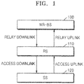
- FIG. 1 illustrates links defined in a system in which a relay station exists according to an embodiment of the present invention.
- a link between a multi-hop relay station (hereinafter, RS) 110 and a multi-hop relay (HR) Base Station (BS) (hereinafter, MR-BS) 100 is called a relay link, and a link between the RS 110 and a subscriber station (hereinafter, SS) 120 called an access link.
- the relay link is divided into a relay uplink and a relay downlink, and the access link is divided into an access uplink and an access downlink.
- the present invention particularly relates to the access uplink among the links. More than two RS can exist between the BS 100 and the SS 120.
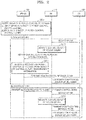
- FIG. 2 is a signaling diagram of a method of controlling power of an access uplink using a relay station according to an embodiment of the present invention.
- the access uplink power control method is largely divided into a method of controlling power of the access uplink in the MR-BS 100 (method I: Centralized MR) and a method of controlling power of the access uplink in the RS 110 (method II : Distributed MR).
- the MR-BS 100 may select one of the method I and the method II.
- the MR- BS 100 selects one of the method I of directly controlling power of the access uplink a nd the method II of controlling power of the access uplink in the RS 110 by considering an entire power control situation of its cell in operation S200.
- the MR-BS 100 transmits the selected method to the RS 110 using a conventional or new message.
- the RS 110 measures channel quality of an access uplink in operation S210.
- the RS 110 transmits a basic Connection Identifier (CID) and channel quality measurement information to the MR-BS 100 or superordinate RS in operation S220.
- the RS 110 can add the channel quality measurement information to a conventional message used between the RS 110 and the MR-BS 100 or generate a new message for reporting the channel quality measurement information, and transmit the message to the MR-BS 100.
- the channel quality measurement information includes reception power measurement information of the access uplink and a power compensation value calculated based on the reception power measurement information, and may further include various kinds of measurement information.
- the MR-BS 100 measures reception power of the an relay uplink and generates a message for power control of the access uplink based on the channel quality measurement information reported from the RS 110 in operation S230, and transmits the power control message to the SS 120 via the RS 110 in operation S240.
- the power control message includes a power compensation value.
- a SS specification may be maintained as it was by using a conventional power control message, e.g. a power control message defined in IEEE 802.16-2004 and IEEE 802.16-2005.
- the MR-BS 100 can perform power control considering the entire cell based on the channel quality measurement information reported from the RS 110.
- the SS 120 immediately reflects the power compensation value included in the received power control message to a transmission power gain in operation S250. Thus, the power of the access uplink is controlled.
- the MR-BS 100 selects a method in which the RS 110 directly controls power of the access uplink in operation S200, the MR-BS 100 informs the RS 110 of the selected method in operation S260, and assigns only resources to a conventional power control message and transmits the power control message to the RS 110.
- the RS 110 measures channel quality of the access uplink in operation S270 and transmits the power control message containing a power compensation value calculated based on the measurement result to the SS 120 in operation S280. That is, the RS 110 measures reception power of the access uplink, calculates the power compensation value based on the measurement result, inserts the calculated power compensation value into a power control message, and transmits the power control message to the SS 120.
- the SS 120 immediately reflects the power compensation value contained in the received power control message to a transmission power gain in operation S290.
- the RS 110 can directly control the power of the access uplink without intervention of the MR-BS 100.
- FIG. 3 is a block diagram of the RS 110 for controlling power of an access uplink according to an embodiment of the present invention.
- the RS 110 includes a quality measurement unit 300, a quality reporting unit 310, and a power controller 320.
- the quality measurement unit 300 measures channel quality of the access uplink between the SS 120 and the RS 110 and generates channel quality measurement information based on the measured channel quality. In detail, the quality measurement unit 300 measures reception power of the access uplink and generates channel quality measurement information containing a power compensation value calculated based on the measured reception power.
- the quality reporting unit 310 reports the channel quality measurement information generated by the quality measurement unit 300 to the MR-BS 100. That is, the quality reporting unit 310 reports the channel quality measurement information to the MR-BS 100 using a message conventionally or newly defined between the MR-BS 100 and the RS 110.
- the power controller 320 generates a message for power control of the access uplink based on the channel quality measured by the quality measurement unit 300 and transmits the power control message to the SS 120.
- the subject of power control can be any of the MR-BS 100 and the RS 110 as illustrated in FIG. 2 , if the RS 110 is selected as the subject of power control by the MR-BS 100, the power controller 320 directly performs the power control of the access uplink.
- the message for power control of the access uplink transmitted from the power controller 320 to the SS 120 may be a conventional power control message applied to the SS 120.
- FIG. 4 is a block diagram of the MR-BS 100 for controlling power of an access uplink according to an embodiment of the present invention.
- the MR-BS 100 includes a channel information receiver 400, a power controller 410, and a control body decision unit 420.
- the channel information receiver 400 receives channel quality measurement information of an access uplink between the SS 120 and the relay 110.
- the control body decision unit 420 decides as described in FIG. 2 whether the subject of power control of the access uplink becomes the MR-BS 100 or the RS 110.
- the power controller 410 If the MR-BS 100 is decided as the subject of power control of the access uplink by the control body decision unit 420, the power controller 410 generates a message for power control of the access uplink based on the received channel quality measurement information and transmits the power control message to the SS 120 via the RS 110.
- the message for power control of the access uplink may be the conventional power control message applied to the SS 120.
- the invention can also be embodied as computer readable codes on a computer readable recording medium.
- the computer readable recording medium is any data storage device that can store data which can be thereafter read by a computer system. Examples of the computer readable recording medium include read-only memory (ROM), random-access memory (RAM), CD-ROMs, magnetic tapes, floppy disks, optical data storage devices, and carrier waves (such as data transmission through the Internet).
- ROM read-only memory
- RAM random-access memory
- CD-ROMs compact discs
- magnetic tapes magnetic tapes
- floppy disks optical data storage devices
- carrier waves such as data transmission through the Internet
- a RS can directly perform fast power control of an access uplink.
- a power control value previously compensated by a RS is used, and thus, fast power control can be performed.
Landscapes
- Engineering & Computer Science (AREA)
- Computer Networks & Wireless Communication (AREA)
- Signal Processing (AREA)
- Quality & Reliability (AREA)
- Mobile Radio Communication Systems (AREA)
Abstract
Description
- The present invention relates to a method of controlling power of access uplink using a relay station and a system thereof.
- This work was supported by the IT R&D program of MIC/IITA [2006-S-011-01, Development of relay/mesh communication system for multi-hop WiBro].
- Recently, Institute of Electrical and Electronics Engineers (IEEE) 802.16 is progressing a standardization project of a multi-hop relay after IEEE 802.16-2004, whi ch is a standard for fixed subscribers' terminals, and IEEE 802.16e-2005, which is a standard for providing mobility of subscriber station (SS), have been published. The purpose of the standardization project performed by IEEE 802.16 Task Group (TG) j is coverage extension and throughput enhancement.
- According to the prior art, a multi-hop relay station has no role in closed-loop power control of terminals, and power control of SS using a multi-hop relay station is not disclosed.
- The present invention provides a method of performing fast power control of an access uplink using a relay station and a system thereof.
- According to an aspect of the present invention, there is provided a method of controlling power in a relay station (RS), the method comprising: measuring channel quality of an access uplink between a subscriber station (SS) and the RS and generating channel quality measurement information based on the measured channel quality; and reporting the channel quality measurement information to a base station (BS) or superordinate RS.
- According to another aspect of the present invention, there is provided a relay station (RS) comprising: a quality measurement unit measuring channel quality of an access uplink between a subscriber station (SS) and the RS and generating channel quality measurement information based on the measured channel quality; and a quality reporting unit reporting the channel quality measurement information to a Base Station (BS) or superordinate RS.
- According to another aspect of the present invention, there is provided a method of controlling power in a relay station(RS), the method comprising: measuring channel quality of an access uplink between a subscriber station (SS) and the RS; and generating a message for power control of the access uplink based on the measured channel quality and transmitting the power control message to the SS.
- According to another aspect of the present invention, there is provided a relay station (RS) comprising: a quality measurement unit measuring channel quality of an access uplink between a subscriber station (SS) and the RS; and a power controller generating a message for power control of the access uplink based on the measured channel quality and transmitting the power control message to the SS.
- According to another aspect of the present invention, there is provided a method of controlling power in a base station (BS), the method comprising: receiving channel quality measurement information of an access uplink between a subscriber station (SS) and a relay station (RS); and generating a message for power control of the access uplink based on the channel quality measurement information and transmitting the power control message to the SS.
- According to another aspect of the present invention, there is provided a base station (BS) comprising: a channel information receiver receiving channel quality measurement information of an access uplink between a subscriber station (SS) and a relay station (RS); and a power controller generating a message for power control of the access uplink based on the channel quality measurement information and transmitting the power control message to the SS.
- Thus, fast power control of an access uplink can be achieved.
- As described above, according to the present invention , a RS can directly perform fast power control of an access uplink. In addition, when a MR-BS performs power control considering the entire cell, a power control value previously compensated by a RS is used, and thus, fast power control can be performed.
-
-
FIG. 1 illustrates links defined in a system in which a relay station exists according to an embodiment of the present invention; -
FIG. 2 is a signaling diagram of a method of controlling power of an access uplink using a relay station according to an embodiment of the present invention; -
FIG. 3 is a block diagram of a relay station (RS) for controlling power of an access uplink according to an embodiment of the present invention; and -
FIG. 4 is a block diagram of a Base Station (BS) for controlling power of an access uplink according to an embodiment of the present invention. - According to an aspect of the present invention, there is provided a method of controlling power in a relay station (RS), the method comprising: measuring channel quality of an access uplink between a subscriber station (SS) and the RS and generating channel quality measurement information based on the measured channel quality; and reporting the channel quality measurement information to a base station (BS) or superordinate RS.
- According to another aspect of the present invention, there is provided a relay station (RS) comprising: a quality measurement unit measuring channel quality of an access uplink between a subscriber station (SS) and the RS and generating channel quality measurement information based on the measured channel quality; and a quality reporting unit reporting the channel quality measurement information to a Base Station (BS) or superordinate RS.
- According to another aspect of the present invention, there is provided a method of controlling power in a relay station(RS), the method comprising: measuring channel quality of an access uplink between a subscriber station (SS) and the RS; and generating a message for power control of the access uplink based on the measured channel quality and transmitting the power control message to the SS.
- According to another aspect of the present invention, there is provided a relay station (RS) comprising: a quality measurement unit measuring channel quality of an access uplink between a subscriber station (SS) and the RS; and a power controller generating a message for power control of the access uplink based on the measured channel quality and transmitting the power control message to the SS.
- According to another aspect of the present invention, there is provided a method of controlling power in a base station (BS), the method comprising: receiving channel quality measurement information of an access uplink between a subscriber station (SS) and a relay station (RS); and generating a message for power control of the access uplink based on the channel quality measurement information and transmitting the power control message to the SS.
- According to another aspect of the present invention, there is provided a base station (BS) comprising: a channel information receiver receiving channel quality measurement information of an access uplink between a subscriber station (SS) and a relay station (RS); and a power controller generating a message for power control of the access uplink based on the channel quality measurement information and transmitting the power control message to the SS.
- Thus, fast power control of an access uplink can be achieved.
- The present invention will be described in detail by explaining preferred embodiments of the invention with reference to the attached drawings.
-
FIG. 1 illustrates links defined in a system in which a relay station exists according to an embodiment of the present invention. - Referring to
FIG. 1 , in an Orthogonal Frequency Division Multiplexing (OFDM) system, a link between a multi-hop relay station (hereinafter, RS) 110 and a multi-hop relay (HR) Base Station (BS) (hereinafter, MR-BS) 100 is called a relay link, and a link between the RS 110 and a subscriber station (hereinafter, SS) 120 called an access link. According to upstream and downstream directions, the relay link is divided into a relay uplink and a relay downlink, and the access link is divided into an access uplink and an access downlink. The present invention particularly relates to the access uplink among the links. More than two RS can exist between the BS 100 and the SS 120. -
FIG. 2 is a signaling diagram of a method of controlling power of an access uplink using a relay station according to an embodiment of the present invention. - Referring to
FIG. 2 , the access uplink power control method is largely divided into a method of controlling power of the access uplink in the MR-BS 100 (method I: Centralized MR) and a method of controlling power of the access uplink in the RS 110 (method II : Distributed MR). - Only one of the method I and the method II can be implemented, if the method I and the method II are implemented together, the MR-BS 100 may select one of the method I and the method II.
- A case where the method I and the method II are implemented together will now be described.
- The MR- BS 100 selects one of the method I of directly controlling power of the access uplink a nd the method II of controlling power of the access uplink in the RS 110 by considering an entire power control situation of its cell in operation S200. The MR-BS 100 transmits the selected method to the RS 110 using a conventional or new message.
- The RS 110 measures channel quality of an access uplink in operation S210. The RS 110 transmits a basic Connection Identifier (CID) and channel quality measurement information to the MR-
BS 100 or superordinate RS in operation S220. In this case, the RS 110 can add the channel quality measurement information to a conventional message used between the RS 110 and the MR-BS 100 or generate a new message for reporting the channel quality measurement information, and transmit the message to the MR-BS 100. The channel quality measurement information includes reception power measurement information of the access uplink and a power compensation value calculated based on the reception power measurement information, and may further include various kinds of measurement information. - The MR-BS 100 measures reception power of the an relay uplink and generates a message for power control of the access uplink based on the channel quality measurement information reported from the RS 110 in operation S230, and transmits the power control message to the SS 120 via the RS 110 in operation S240. The power control message includes a power compensation value.
- Meanwhile, for the message for power control of the access uplink, a SS specification may be maintained as it was by using a conventional power control message, e.g. a power control message defined in IEEE 802.16-2004 and IEEE 802.16-2005. The MR-BS 100 can perform power control considering the entire cell based on the channel quality measurement information reported from the RS 110.
- The SS 120 immediately reflects the power compensation value included in the received power control message to a transmission power gain in operation S250. Thus, the power of the access uplink is controlled.
- If the MR-BS 100 selects a method in which the RS 110 directly controls power of the access uplink in operation S200, the MR-BS 100 informs the
RS 110 of the selected method in operation S260, and assigns only resources to a conventional power control message and transmits the power control message to the RS 110. - The RS 110 measures channel quality of the access uplink in operation S270 and transmits the power control message containing a power compensation value calculated based on the measurement result to the
SS 120 in operation S280. That is, the RS 110 measures reception power of the access uplink, calculates the power compensation value based on the measurement result, inserts the calculated power compensation value into a power control message, and transmits the power control message to theSS 120. The SS 120 immediately reflects the power compensation value contained in the received power control message to a transmission power gain in operation S290. Thus, the RS 110 can directly control the power of the access uplink without intervention of the MR-BS 100. -
FIG. 3 is a block diagram of theRS 110 for controlling power of an access uplink according to an embodiment of the present invention. - Referring to
FIGS. 1 and3 , the RS 110 includes aquality measurement unit 300, aquality reporting unit 310, and apower controller 320. - The
quality measurement unit 300 measures channel quality of the access uplink between theSS 120 and theRS 110 and generates channel quality measurement information based on the measured channel quality. In detail, thequality measurement unit 300 measures reception power of the access uplink and generates channel quality measurement information containing a power compensation value calculated based on the measured reception power. - The
quality reporting unit 310 reports the channel quality measurement information generated by thequality measurement unit 300 to the MR-BS 100. That is, thequality reporting unit 310 reports the channel quality measurement information to the MR-BS 100 using a message conventionally or newly defined between the MR-BS 100 and theRS 110. - The
power controller 320 generates a message for power control of the access uplink based on the channel quality measured by thequality measurement unit 300 and transmits the power control message to theSS 120. In the power control of the access uplink according to the current embodiment, since the subject of power control can be any of the MR-BS 100 and theRS 110 as illustrated inFIG. 2 , if theRS 110 is selected as the subject of power control by the MR-BS 100, thepower controller 320 directly performs the power control of the access uplink. - The message for power control of the access uplink transmitted from the
power controller 320 to theSS 120 may be a conventional power control message applied to theSS 120. -
FIG. 4 is a block diagram of the MR-BS 100 for controlling power of an access uplink according to an embodiment of the present invention. - Referring to
FIGS. 1 and4 , the MR-BS 100 includes achannel information receiver 400, apower controller 410, and a controlbody decision unit 420. - The
channel information receiver 400 receives channel quality measurement information of an access uplink between theSS 120 and therelay 110. The controlbody decision unit 420 decides as described inFIG. 2 whether the subject of power control of the access uplink becomes the MR-BS 100 or theRS 110. - If the MR-
BS 100 is decided as the subject of power control of the access uplink by the controlbody decision unit 420, thepower controller 410 generates a message for power control of the access uplink based on the received channel quality measurement information and transmits the power control message to theSS 120 via theRS 110. In this case, the message for power control of the access uplink may be the conventional power control message applied to theSS 120. - The invention can also be embodied as computer readable codes on a computer readable recording medium. The computer readable recording medium is any data storage device that can store data which can be thereafter read by a computer system. Examples of the computer readable recording medium include read-only memory (ROM), random-access memory (RAM), CD-ROMs, magnetic tapes, floppy disks, optical data storage devices, and carrier waves (such as data transmission through the Internet). The computer readable recording medium can also be distributed over network coupled computer systems so that the computer readable code is stored and executed in a distributed fashion.
- As described above, according to the present invention , a RS can directly perform fast power control of an access uplink. In addition, when a MR-BS performs power control considering the entire cell, a power control value previously compensated by a RS is used, and thus, fast power control can be performed.
- While this invention has been particularly shown and described with reference to preferred embodiments thereof, it will be understood by those skilled in the art that various changes in form and details may be made therein without departing from the spirit and scope of the invention as defined by the appended claims. The preferred embodiments should be considered in descriptive sense only and not for purposes of limitation. Therefore, the scope of the invention is defined not by the detailed description of the invention but by the appended claims, and all differences within the scope will be construed as being included in the present invention.
Claims (4)
- A method of controlling power in communication system including a relay station (RS) and a base station (BS), the method comprising:transmitting (S260), by the BS, a message related to power control to the RS;measuring, by the RS, channel quality of an access uplink between a subscriber station (SS) and the RS;generating, by the RS, power control message for the access uplink based on the measured channel quality; andtransmitting, by the RS, the power control message to the SS.
- The method of claim 1, wherein the SS compensates power of the access uplink based on the power control message.
- A method of controlling power in communication system including a relay station (RS) and a base station (BS), the method comprising:measuring, by the RS, channel quality of an access uplink between a subscriber station (SS) and the RS;generating, by the RS, channel quality measurement information based on the measured channel quality;reporting, by the RS, the channel quality measurement information to the base station (BS) or superordinate RS;generating, by the BS, power control message for the access uplink based on the channel quality measurement information; andtransmitting, by the BS, the power control message to the RS or to the SS via the RS.
- The method of claim 3, wherein the SS compensates power of the access uplink based on the power control message.
Applications Claiming Priority (4)
| Application Number | Priority Date | Filing Date | Title |
|---|---|---|---|
| KR20060107670 | 2006-11-02 | ||
| KR1020070040971A KR101386211B1 (en) | 2006-11-02 | 2007-04-26 | Method of access-uplink power control using mobile multi-hop relay and system thereof |
| EP07833783.9A EP2080292B1 (en) | 2006-11-02 | 2007-10-31 | Method of controlling power of access uplink using relay station and system thereof |
| PCT/KR2007/005475 WO2008054150A1 (en) | 2006-11-02 | 2007-10-31 | Method of controlling power of access uplink using relay station and system thereof |
Related Parent Applications (2)
| Application Number | Title | Priority Date | Filing Date |
|---|---|---|---|
| EP07833783.9A Division EP2080292B1 (en) | 2006-11-02 | 2007-10-31 | Method of controlling power of access uplink using relay station and system thereof |
| EP07833783.9A Division-Into EP2080292B1 (en) | 2006-11-02 | 2007-10-31 | Method of controlling power of access uplink using relay station and system thereof |
Publications (2)
| Publication Number | Publication Date |
|---|---|
| EP3223440A1 true EP3223440A1 (en) | 2017-09-27 |
| EP3223440B1 EP3223440B1 (en) | 2021-03-24 |
Family
ID=39648193
Family Applications (2)
| Application Number | Title | Priority Date | Filing Date |
|---|---|---|---|
| EP17166277.8A Active EP3223440B1 (en) | 2006-11-02 | 2007-10-31 | Method of controlling power of access uplink using relay station |
| EP07833783.9A Active EP2080292B1 (en) | 2006-11-02 | 2007-10-31 | Method of controlling power of access uplink using relay station and system thereof |
Family Applications After (1)
| Application Number | Title | Priority Date | Filing Date |
|---|---|---|---|
| EP07833783.9A Active EP2080292B1 (en) | 2006-11-02 | 2007-10-31 | Method of controlling power of access uplink using relay station and system thereof |
Country Status (4)
| Country | Link |
|---|---|
| US (1) | US8200274B2 (en) |
| EP (2) | EP3223440B1 (en) |
| KR (1) | KR101386211B1 (en) |
| WO (1) | WO2008054150A1 (en) |
Families Citing this family (15)
| Publication number | Priority date | Publication date | Assignee | Title |
|---|---|---|---|---|
| CN101237278A (en) * | 2007-01-30 | 2008-08-06 | 西门子通信技术(北京)有限公司 | Method, system, relay station and base station for transmitting data in mobile communication |
| EP2232720B1 (en) * | 2007-12-14 | 2014-06-11 | Telefonaktiebolaget L M Ericsson (publ) | Uplink transmit power control |
| US8462743B2 (en) | 2008-01-25 | 2013-06-11 | Nokia Siemens Networks Oy | Method, apparatus and computer program for signaling channel quality information in a network that employs relay nodes |
| KR101383049B1 (en) * | 2008-05-27 | 2014-04-09 | 에스케이텔레콤 주식회사 | Method for controlling power of femto bts, and femto bts applied to the same |
| PL2342942T3 (en) * | 2008-09-29 | 2021-12-06 | Electronics And Telecommunications Research Institute | Apparatus and method for transmitting and receiving data in wireless communication system using relay |
| CN102172072A (en) * | 2008-10-07 | 2011-08-31 | 富士通株式会社 | Relay apparatus, terminal apparatus and communication system |
| US8804585B2 (en) * | 2009-01-09 | 2014-08-12 | Qualcomm Incorporated | Special management connection between base station and relay stations in multihop relay systems for controlling sleep-mode |
| US20120230249A1 (en) * | 2009-11-10 | 2012-09-13 | Shusaku Fukumoto | Wireless communication system, base station device, mobile station device, and wireless communication method |
| US20110136484A1 (en) * | 2009-12-07 | 2011-06-09 | Volker Braun | User admission, power, rate and mobility control method for relay communication systems |
| EP2592876B1 (en) * | 2010-07-05 | 2015-01-21 | Hytera Communications Corp., Ltd. | Terminal in digital mobile radio relay system, transmission power regulation method and system thereof |
| KR101665568B1 (en) * | 2010-12-08 | 2016-10-12 | 삼성전자주식회사 | Method and apparatus for distributed transmission power control in wireless networks |
| CN103369646A (en) * | 2012-04-01 | 2013-10-23 | 上海交通大学 | Power distribution method, system and device |
| US9265047B2 (en) | 2012-04-04 | 2016-02-16 | Qualcomm Incorporated | Procedures to activate opportunistic relays |
| WO2015139212A1 (en) * | 2014-03-18 | 2015-09-24 | 华为技术有限公司 | Power control method and device |
| CN113615229A (en) * | 2019-03-29 | 2021-11-05 | 株式会社Ntt都科摩 | Relay device |
Citations (1)
| Publication number | Priority date | Publication date | Assignee | Title |
|---|---|---|---|---|
| WO2006101013A1 (en) * | 2005-03-18 | 2006-09-28 | Matsushita Electric Industrial Co., Ltd. | Mobile station apparatus and wireless communication method |
Family Cites Families (12)
| Publication number | Priority date | Publication date | Assignee | Title |
|---|---|---|---|---|
| US4675863A (en) * | 1985-03-20 | 1987-06-23 | International Mobile Machines Corp. | Subscriber RF telephone system for providing multiple speech and/or data signals simultaneously over either a single or a plurality of RF channels |
| WO2001048942A1 (en) | 1999-12-29 | 2001-07-05 | Airnet Communications Corporation | Reporting system for wireless repeater for indicating uplink mobile receive level |
| US7257101B2 (en) * | 2002-07-03 | 2007-08-14 | Arraycomm, Llc | Selective power control messaging |
| KR20040041289A (en) * | 2002-11-09 | 2004-05-17 | 삼성전자주식회사 | Apparatus and method for controlling transmission power serving multimedia broadcast/multicast service in mobile communication system |
| US20060154633A1 (en) * | 2003-01-29 | 2006-07-13 | Hai Wang | Uplink sinr estimation |
| US7215930B2 (en) | 2003-03-06 | 2007-05-08 | Qualcomm, Incorporated | Method and apparatus for providing uplink signal-to-noise ratio (SNR) estimation in a wireless communication |
| CN1535037A (en) | 2003-04-01 | 2004-10-06 | �ʼҷ����ֵ��ӹɷ�����˾ | Method and system used for multijump communication managemnt in radio communication network |
| SE0301076D0 (en) * | 2003-04-08 | 2003-04-08 | Ericsson Telefon Ab L M | A method in a telecommunication system |
| KR100606129B1 (en) * | 2003-04-30 | 2006-07-28 | 삼성전자주식회사 | Channel Quality Measurement and Reporting Method in Broadband Wireless Access Communication Systems |
| KR100689491B1 (en) * | 2004-07-12 | 2007-03-02 | 삼성전자주식회사 | Apparatus and method for determining access power in a mobile communication system |
| US7623490B2 (en) | 2004-12-22 | 2009-11-24 | Qualcomm Incorporated | Systems and methods that utilize a capacity-based signal-to-noise ratio to predict and improve mobile communication |
| US7873338B2 (en) * | 2006-11-06 | 2011-01-18 | Motorola Mobility, Inc. | Method and apparatus for determining an appropriate link path in a multi-hop communication system |
-
2007
- 2007-04-26 KR KR1020070040971A patent/KR101386211B1/en active Active
- 2007-10-31 EP EP17166277.8A patent/EP3223440B1/en active Active
- 2007-10-31 WO PCT/KR2007/005475 patent/WO2008054150A1/en not_active Ceased
- 2007-10-31 US US12/513,273 patent/US8200274B2/en active Active
- 2007-10-31 EP EP07833783.9A patent/EP2080292B1/en active Active
Patent Citations (2)
| Publication number | Priority date | Publication date | Assignee | Title |
|---|---|---|---|---|
| WO2006101013A1 (en) * | 2005-03-18 | 2006-09-28 | Matsushita Electric Industrial Co., Ltd. | Mobile station apparatus and wireless communication method |
| EP1852987A1 (en) * | 2005-03-18 | 2007-11-07 | Matsushita Electric Industrial Co., Ltd. | Mobile station apparatus and wireless communication method |
Also Published As
| Publication number | Publication date |
|---|---|
| EP2080292A4 (en) | 2013-05-22 |
| US8200274B2 (en) | 2012-06-12 |
| KR20080040545A (en) | 2008-05-08 |
| WO2008054150A1 (en) | 2008-05-08 |
| US20100069110A1 (en) | 2010-03-18 |
| KR101386211B1 (en) | 2014-04-17 |
| EP2080292A1 (en) | 2009-07-22 |
| EP3223440B1 (en) | 2021-03-24 |
| EP2080292B1 (en) | 2017-05-24 |
Similar Documents
| Publication | Publication Date | Title |
|---|---|---|
| EP3223440B1 (en) | Method of controlling power of access uplink using relay station | |
| AU2009315367B2 (en) | Creation and signalling of UE lists to support frequency selective repeater operation | |
| KR100975743B1 (en) | Signal relay method and system in wireless communication system | |
| KR101571563B1 (en) | A method of controlling uplink power in a multi-cell cooperative wireless communication system and a terminal supporting the same | |
| EP2245760B1 (en) | Power control at a relay station in a wireless network | |
| CN102318228B (en) | Method for transmitting uplink signal and feedback information and relay device using the method | |
| US8233398B2 (en) | Apparatus and method for transmitting frame information in multi-hop relay broadband wireless access communication system | |
| US20190253136A1 (en) | An adaptive multiple access scheme in integrated access and backhaul networks | |
| US10880906B2 (en) | Apparatuses, methods and computer programs for implementing fairness and complexity-constrained a non-orthogonal multiple access (NOMA) scheme | |
| US8570947B2 (en) | Scheduling method in wireless communication system using relay station | |
| US8369261B2 (en) | Method and apparatus for interference reduction | |
| EP2557857A1 (en) | Wireless base station device, mobile terminal device, and cell selection method | |
| US12408131B2 (en) | Network node, device to device user equipment, and methods in a radio communications network | |
| WO2011074828A2 (en) | Method and apparatus for transmitting feedback information in a wireless communication system containing a relay station | |
| EP3869708B1 (en) | Downstream iab node, method to operate a downstream iab node, upstream iab node, method to operate an upstream iab node | |
| KR101307532B1 (en) | Method for Determining Transfer Mode in Mobile Communication System | |
| KR20080022700A (en) | Ranging method and apparatus in communication system including relay station and system therefor | |
| US20240032009A1 (en) | Iab indication method, device, and medium | |
| CN121128258A (en) | Configuration for uplink reference signals | |
| CN120343717A (en) | A communication method, device and system |
Legal Events
| Date | Code | Title | Description |
|---|---|---|---|
| PUAI | Public reference made under article 153(3) epc to a published international application that has entered the european phase |
Free format text: ORIGINAL CODE: 0009012 |
|
| STAA | Information on the status of an ep patent application or granted ep patent |
Free format text: STATUS: THE APPLICATION HAS BEEN PUBLISHED |
|
| AC | Divisional application: reference to earlier application |
Ref document number: 2080292 Country of ref document: EP Kind code of ref document: P |
|
| AK | Designated contracting states |
Kind code of ref document: A1 Designated state(s): AT BE BG CH CY CZ DE DK EE ES FI FR GB GR HU IE IS IT LI LT LU LV MC MT NL PL PT RO SE SI SK TR |
|
| STAA | Information on the status of an ep patent application or granted ep patent |
Free format text: STATUS: REQUEST FOR EXAMINATION WAS MADE |
|
| 17P | Request for examination filed |
Effective date: 20180327 |
|
| RBV | Designated contracting states (corrected) |
Designated state(s): AT BE BG CH CY CZ DE DK EE ES FI FR GB GR HU IE IS IT LI LT LU LV MC MT NL PL PT RO SE SI SK TR |
|
| STAA | Information on the status of an ep patent application or granted ep patent |
Free format text: STATUS: EXAMINATION IS IN PROGRESS |
|
| 17Q | First examination report despatched |
Effective date: 20180514 |
|
| RIC1 | Information provided on ipc code assigned before grant |
Ipc: H04W 52/14 20090101ALN20200901BHEP Ipc: H04W 52/46 20090101ALI20200901BHEP Ipc: H04B 7/155 20060101AFI20200901BHEP Ipc: H04W 52/24 20090101ALN20200901BHEP Ipc: H04W 52/50 20090101ALN20200901BHEP |
|
| GRAP | Despatch of communication of intention to grant a patent |
Free format text: ORIGINAL CODE: EPIDOSNIGR1 |
|
| STAA | Information on the status of an ep patent application or granted ep patent |
Free format text: STATUS: GRANT OF PATENT IS INTENDED |
|
| INTG | Intention to grant announced |
Effective date: 20201016 |
|
| RIC1 | Information provided on ipc code assigned before grant |
Ipc: H04W 52/14 20090101ALN20201002BHEP Ipc: H04W 52/24 20090101ALN20201002BHEP Ipc: H04B 7/155 20060101AFI20201002BHEP Ipc: H04W 52/50 20090101ALN20201002BHEP Ipc: H04W 52/46 20090101ALI20201002BHEP |
|
| GRAS | Grant fee paid |
Free format text: ORIGINAL CODE: EPIDOSNIGR3 |
|
| GRAA | (expected) grant |
Free format text: ORIGINAL CODE: 0009210 |
|
| STAA | Information on the status of an ep patent application or granted ep patent |
Free format text: STATUS: THE PATENT HAS BEEN GRANTED |
|
| AC | Divisional application: reference to earlier application |
Ref document number: 2080292 Country of ref document: EP Kind code of ref document: P |
|
| AK | Designated contracting states |
Kind code of ref document: B1 Designated state(s): AT BE BG CH CY CZ DE DK EE ES FI FR GB GR HU IE IS IT LI LT LU LV MC MT NL PL PT RO SE SI SK TR |
|
| REG | Reference to a national code |
Ref country code: GB Ref legal event code: FG4D |
|
| REG | Reference to a national code |
Ref country code: CH Ref legal event code: EP |
|
| REG | Reference to a national code |
Ref country code: IE Ref legal event code: FG4D |
|
| REG | Reference to a national code |
Ref country code: AT Ref legal event code: REF Ref document number: 1375568 Country of ref document: AT Kind code of ref document: T Effective date: 20210415 Ref country code: DE Ref legal event code: R096 Ref document number: 602007061014 Country of ref document: DE |
|
| REG | Reference to a national code |
Ref country code: LT Ref legal event code: MG9D |
|
| PG25 | Lapsed in a contracting state [announced via postgrant information from national office to epo] |
Ref country code: FI Free format text: LAPSE BECAUSE OF FAILURE TO SUBMIT A TRANSLATION OF THE DESCRIPTION OR TO PAY THE FEE WITHIN THE PRESCRIBED TIME-LIMIT Effective date: 20210324 Ref country code: GR Free format text: LAPSE BECAUSE OF FAILURE TO SUBMIT A TRANSLATION OF THE DESCRIPTION OR TO PAY THE FEE WITHIN THE PRESCRIBED TIME-LIMIT Effective date: 20210625 Ref country code: BG Free format text: LAPSE BECAUSE OF FAILURE TO SUBMIT A TRANSLATION OF THE DESCRIPTION OR TO PAY THE FEE WITHIN THE PRESCRIBED TIME-LIMIT Effective date: 20210624 |
|
| PG25 | Lapsed in a contracting state [announced via postgrant information from national office to epo] |
Ref country code: LV Free format text: LAPSE BECAUSE OF FAILURE TO SUBMIT A TRANSLATION OF THE DESCRIPTION OR TO PAY THE FEE WITHIN THE PRESCRIBED TIME-LIMIT Effective date: 20210324 Ref country code: SE Free format text: LAPSE BECAUSE OF FAILURE TO SUBMIT A TRANSLATION OF THE DESCRIPTION OR TO PAY THE FEE WITHIN THE PRESCRIBED TIME-LIMIT Effective date: 20210324 |
|
| REG | Reference to a national code |
Ref country code: NL Ref legal event code: MP Effective date: 20210324 |
|
| REG | Reference to a national code |
Ref country code: AT Ref legal event code: MK05 Ref document number: 1375568 Country of ref document: AT Kind code of ref document: T Effective date: 20210324 |
|
| PG25 | Lapsed in a contracting state [announced via postgrant information from national office to epo] |
Ref country code: NL Free format text: LAPSE BECAUSE OF FAILURE TO SUBMIT A TRANSLATION OF THE DESCRIPTION OR TO PAY THE FEE WITHIN THE PRESCRIBED TIME-LIMIT Effective date: 20210324 |
|
| PG25 | Lapsed in a contracting state [announced via postgrant information from national office to epo] |
Ref country code: CZ Free format text: LAPSE BECAUSE OF FAILURE TO SUBMIT A TRANSLATION OF THE DESCRIPTION OR TO PAY THE FEE WITHIN THE PRESCRIBED TIME-LIMIT Effective date: 20210324 Ref country code: EE Free format text: LAPSE BECAUSE OF FAILURE TO SUBMIT A TRANSLATION OF THE DESCRIPTION OR TO PAY THE FEE WITHIN THE PRESCRIBED TIME-LIMIT Effective date: 20210324 Ref country code: LT Free format text: LAPSE BECAUSE OF FAILURE TO SUBMIT A TRANSLATION OF THE DESCRIPTION OR TO PAY THE FEE WITHIN THE PRESCRIBED TIME-LIMIT Effective date: 20210324 Ref country code: AT Free format text: LAPSE BECAUSE OF FAILURE TO SUBMIT A TRANSLATION OF THE DESCRIPTION OR TO PAY THE FEE WITHIN THE PRESCRIBED TIME-LIMIT Effective date: 20210324 |
|
| PG25 | Lapsed in a contracting state [announced via postgrant information from national office to epo] |
Ref country code: PT Free format text: LAPSE BECAUSE OF FAILURE TO SUBMIT A TRANSLATION OF THE DESCRIPTION OR TO PAY THE FEE WITHIN THE PRESCRIBED TIME-LIMIT Effective date: 20210726 Ref country code: PL Free format text: LAPSE BECAUSE OF FAILURE TO SUBMIT A TRANSLATION OF THE DESCRIPTION OR TO PAY THE FEE WITHIN THE PRESCRIBED TIME-LIMIT Effective date: 20210324 Ref country code: RO Free format text: LAPSE BECAUSE OF FAILURE TO SUBMIT A TRANSLATION OF THE DESCRIPTION OR TO PAY THE FEE WITHIN THE PRESCRIBED TIME-LIMIT Effective date: 20210324 Ref country code: SK Free format text: LAPSE BECAUSE OF FAILURE TO SUBMIT A TRANSLATION OF THE DESCRIPTION OR TO PAY THE FEE WITHIN THE PRESCRIBED TIME-LIMIT Effective date: 20210324 Ref country code: IS Free format text: LAPSE BECAUSE OF FAILURE TO SUBMIT A TRANSLATION OF THE DESCRIPTION OR TO PAY THE FEE WITHIN THE PRESCRIBED TIME-LIMIT Effective date: 20210724 |
|
| REG | Reference to a national code |
Ref country code: DE Ref legal event code: R097 Ref document number: 602007061014 Country of ref document: DE |
|
| PG25 | Lapsed in a contracting state [announced via postgrant information from national office to epo] |
Ref country code: DK Free format text: LAPSE BECAUSE OF FAILURE TO SUBMIT A TRANSLATION OF THE DESCRIPTION OR TO PAY THE FEE WITHIN THE PRESCRIBED TIME-LIMIT Effective date: 20210324 Ref country code: ES Free format text: LAPSE BECAUSE OF FAILURE TO SUBMIT A TRANSLATION OF THE DESCRIPTION OR TO PAY THE FEE WITHIN THE PRESCRIBED TIME-LIMIT Effective date: 20210324 |
|
| PLBE | No opposition filed within time limit |
Free format text: ORIGINAL CODE: 0009261 |
|
| STAA | Information on the status of an ep patent application or granted ep patent |
Free format text: STATUS: NO OPPOSITION FILED WITHIN TIME LIMIT |
|
| PG25 | Lapsed in a contracting state [announced via postgrant information from national office to epo] |
Ref country code: SI Free format text: LAPSE BECAUSE OF FAILURE TO SUBMIT A TRANSLATION OF THE DESCRIPTION OR TO PAY THE FEE WITHIN THE PRESCRIBED TIME-LIMIT Effective date: 20210324 |
|
| 26N | No opposition filed |
Effective date: 20220104 |
|
| REG | Reference to a national code |
Ref country code: CH Ref legal event code: PL |
|
| PG25 | Lapsed in a contracting state [announced via postgrant information from national office to epo] |
Ref country code: IS Free format text: LAPSE BECAUSE OF FAILURE TO SUBMIT A TRANSLATION OF THE DESCRIPTION OR TO PAY THE FEE WITHIN THE PRESCRIBED TIME-LIMIT Effective date: 20210724 |
|
| REG | Reference to a national code |
Ref country code: BE Ref legal event code: MM Effective date: 20211031 |
|
| GBPC | Gb: european patent ceased through non-payment of renewal fee |
Effective date: 20211031 |
|
| PG25 | Lapsed in a contracting state [announced via postgrant information from national office to epo] |
Ref country code: MC Free format text: LAPSE BECAUSE OF FAILURE TO SUBMIT A TRANSLATION OF THE DESCRIPTION OR TO PAY THE FEE WITHIN THE PRESCRIBED TIME-LIMIT Effective date: 20210324 |
|
| PG25 | Lapsed in a contracting state [announced via postgrant information from national office to epo] |
Ref country code: LU Free format text: LAPSE BECAUSE OF NON-PAYMENT OF DUE FEES Effective date: 20211031 Ref country code: GB Free format text: LAPSE BECAUSE OF NON-PAYMENT OF DUE FEES Effective date: 20211031 Ref country code: BE Free format text: LAPSE BECAUSE OF NON-PAYMENT OF DUE FEES Effective date: 20211031 |
|
| PG25 | Lapsed in a contracting state [announced via postgrant information from national office to epo] |
Ref country code: LI Free format text: LAPSE BECAUSE OF NON-PAYMENT OF DUE FEES Effective date: 20211031 Ref country code: CH Free format text: LAPSE BECAUSE OF NON-PAYMENT OF DUE FEES Effective date: 20211031 |
|
| PG25 | Lapsed in a contracting state [announced via postgrant information from national office to epo] |
Ref country code: FR Free format text: LAPSE BECAUSE OF NON-PAYMENT OF DUE FEES Effective date: 20211031 |
|
| PG25 | Lapsed in a contracting state [announced via postgrant information from national office to epo] |
Ref country code: IE Free format text: LAPSE BECAUSE OF NON-PAYMENT OF DUE FEES Effective date: 20211031 |
|
| PG25 | Lapsed in a contracting state [announced via postgrant information from national office to epo] |
Ref country code: IT Free format text: LAPSE BECAUSE OF FAILURE TO SUBMIT A TRANSLATION OF THE DESCRIPTION OR TO PAY THE FEE WITHIN THE PRESCRIBED TIME-LIMIT Effective date: 20210324 |
|
| PG25 | Lapsed in a contracting state [announced via postgrant information from national office to epo] |
Ref country code: HU Free format text: LAPSE BECAUSE OF FAILURE TO SUBMIT A TRANSLATION OF THE DESCRIPTION OR TO PAY THE FEE WITHIN THE PRESCRIBED TIME-LIMIT; INVALID AB INITIO Effective date: 20071031 Ref country code: CY Free format text: LAPSE BECAUSE OF FAILURE TO SUBMIT A TRANSLATION OF THE DESCRIPTION OR TO PAY THE FEE WITHIN THE PRESCRIBED TIME-LIMIT Effective date: 20210324 |
|
| PG25 | Lapsed in a contracting state [announced via postgrant information from national office to epo] |
Ref country code: MT Free format text: LAPSE BECAUSE OF FAILURE TO SUBMIT A TRANSLATION OF THE DESCRIPTION OR TO PAY THE FEE WITHIN THE PRESCRIBED TIME-LIMIT Effective date: 20210324 |
|
| PG25 | Lapsed in a contracting state [announced via postgrant information from national office to epo] |
Ref country code: TR Free format text: LAPSE BECAUSE OF FAILURE TO SUBMIT A TRANSLATION OF THE DESCRIPTION OR TO PAY THE FEE WITHIN THE PRESCRIBED TIME-LIMIT Effective date: 20210324 |
|
| PGFP | Annual fee paid to national office [announced via postgrant information from national office to epo] |
Ref country code: DE Payment date: 20250922 Year of fee payment: 19 |