EP3223254A1 - Remote control device - Google Patents
Remote control device Download PDFInfo
- Publication number
- EP3223254A1 EP3223254A1 EP16200342.0A EP16200342A EP3223254A1 EP 3223254 A1 EP3223254 A1 EP 3223254A1 EP 16200342 A EP16200342 A EP 16200342A EP 3223254 A1 EP3223254 A1 EP 3223254A1
- Authority
- EP
- European Patent Office
- Prior art keywords
- module
- remote control
- control device
- energy storage
- button
- Prior art date
- Legal status (The legal status is an assumption and is not a legal conclusion. Google has not performed a legal analysis and makes no representation as to the accuracy of the status listed.)
- Withdrawn
Links
Images



Classifications
-
- H—ELECTRICITY
- H02—GENERATION; CONVERSION OR DISTRIBUTION OF ELECTRIC POWER
- H02N—ELECTRIC MACHINES NOT OTHERWISE PROVIDED FOR
- H02N11/00—Generators or motors not provided for elsewhere; Alleged perpetua mobilia obtained by electric or magnetic means
- H02N11/002—Generators
-
- G—PHYSICS
- G05—CONTROLLING; REGULATING
- G05B—CONTROL OR REGULATING SYSTEMS IN GENERAL; FUNCTIONAL ELEMENTS OF SUCH SYSTEMS; MONITORING OR TESTING ARRANGEMENTS FOR SUCH SYSTEMS OR ELEMENTS
- G05B19/00—Program-control systems
- G05B19/02—Program-control systems electric
- G05B19/04—Program control other than numerical control, i.e. in sequence controllers or logic controllers
- G05B19/10—Program control other than numerical control, i.e. in sequence controllers or logic controllers using selector switches
- G05B19/106—Program control other than numerical control, i.e. in sequence controllers or logic controllers using selector switches for selecting a program, variable or parameter
-
- G—PHYSICS
- G08—SIGNALLING
- G08C—TRANSMISSION SYSTEMS FOR MEASURED VALUES, CONTROL OR SIMILAR SIGNALS
- G08C17/00—Arrangements for transmitting signals characterised by the use of a wireless electrical link
- G08C17/02—Arrangements for transmitting signals characterised by the use of a wireless electrical link using a radio link
-
- G—PHYSICS
- G08—SIGNALLING
- G08C—TRANSMISSION SYSTEMS FOR MEASURED VALUES, CONTROL OR SIMILAR SIGNALS
- G08C17/00—Arrangements for transmitting signals characterised by the use of a wireless electrical link
- G08C17/06—Arrangements for transmitting signals characterised by the use of a wireless electrical link using capacity coupling
-
- G—PHYSICS
- G08—SIGNALLING
- G08C—TRANSMISSION SYSTEMS FOR MEASURED VALUES, CONTROL OR SIMILAR SIGNALS
- G08C19/00—Electric signal transmission systems
- G08C19/16—Electric signal transmission systems in which transmission is by pulses
- G08C19/28—Electric signal transmission systems in which transmission is by pulses using pulse code
-
- G—PHYSICS
- G08—SIGNALLING
- G08C—TRANSMISSION SYSTEMS FOR MEASURED VALUES, CONTROL OR SIMILAR SIGNALS
- G08C21/00—Systems for transmitting the position of an object with respect to a predetermined reference system, e.g. tele-autographic system
-
- G—PHYSICS
- G08—SIGNALLING
- G08C—TRANSMISSION SYSTEMS FOR MEASURED VALUES, CONTROL OR SIMILAR SIGNALS
- G08C23/00—Non-electrical signal transmission systems, e.g. optical systems
- G08C23/04—Non-electrical signal transmission systems, e.g. optical systems using light waves, e.g. infrared
-
- H—ELECTRICITY
- H04—ELECTRIC COMMUNICATION TECHNIQUE
- H04Q—SELECTING
- H04Q9/00—Arrangements in telecontrol or telemetry systems for selectively calling a substation from a main station, in which substation desired apparatus is selected for applying a control signal thereto or for obtaining measured values therefrom
-
- H—ELECTRICITY
- H10—SEMICONDUCTOR DEVICES; ELECTRIC SOLID-STATE DEVICES NOT OTHERWISE PROVIDED FOR
- H10N—ELECTRIC SOLID-STATE DEVICES NOT OTHERWISE PROVIDED FOR
- H10N10/00—Thermoelectric devices comprising a junction of dissimilar materials, i.e. devices exhibiting Seebeck or Peltier effects
-
- G—PHYSICS
- G05—CONTROLLING; REGULATING
- G05B—CONTROL OR REGULATING SYSTEMS IN GENERAL; FUNCTIONAL ELEMENTS OF SUCH SYSTEMS; MONITORING OR TESTING ARRANGEMENTS FOR SUCH SYSTEMS OR ELEMENTS
- G05B2219/00—Program-control systems
- G05B2219/20—Pc systems
- G05B2219/26—Pc applications
- G05B2219/2639—Energy management, use maximum of cheap power, keep peak load low
-
- G—PHYSICS
- G08—SIGNALLING
- G08C—TRANSMISSION SYSTEMS FOR MEASURED VALUES, CONTROL OR SIMILAR SIGNALS
- G08C2201/00—Transmission systems of control signals via wireless link
- G08C2201/10—Power supply of remote control devices
-
- G—PHYSICS
- G08—SIGNALLING
- G08C—TRANSMISSION SYSTEMS FOR MEASURED VALUES, CONTROL OR SIMILAR SIGNALS
- G08C2201/00—Transmission systems of control signals via wireless link
- G08C2201/10—Power supply of remote control devices
- G08C2201/11—Energy harvesting
-
- H—ELECTRICITY
- H04—ELECTRIC COMMUNICATION TECHNIQUE
- H04Q—SELECTING
- H04Q2209/00—Arrangements in telecontrol or telemetry systems
- H04Q2209/40—Arrangements in telecontrol or telemetry systems using a wireless architecture
-
- H—ELECTRICITY
- H04—ELECTRIC COMMUNICATION TECHNIQUE
- H04Q—SELECTING
- H04Q2209/00—Arrangements in telecontrol or telemetry systems
- H04Q2209/80—Arrangements in the sub-station, i.e. sensing device
- H04Q2209/88—Providing power supply at the sub-station
- H04Q2209/886—Providing power supply at the sub-station using energy harvesting, e.g. solar, wind or mechanical
Definitions
- the present disclosure generally relates to the technical field of wireless remote control, and more particularly to a remote control device.
- Appliances such as, televisions, air conditioners and stereos etc.
- these appliances are everywhere in modem life.
- these appliances are each configured with a remote control device (with which control of the appliances over a short distance may be implemented) by their manufacturers, before they leave the factory.
- the remote control device includes a shell, which is configured with a thermoelectric generation module, a central processor, a button module and a radio frequency (RF) module.
- the thermoelectric generation module is connected with each of the central processor, the button module and the RF module.
- the central processor is connected with the button module and the RF module.
- the thermoelectric generation module includes an electricity generation unit.
- the electricity generation unit includes two metal sheets which are made of different materials. The two metal sheets form a closed loop circuit via two connection points. The electricity generation unit is able to generate a thermoelectromotive force based on a temperature difference between the two connection points, and powers the central processor, the button module and the RF module by the thermoelectromotive force.
- the remote control device may further include an energy storage module, which is connected with the thermoelectric generation module.
- the energy storage module may be a storage capacitor.
- the remote control device may further include an energy indicator which is connected with the energy storage module.
- the energy indicator has two states of light-up and turn-off. When there is no electric energy stored in the energy storage module, the energy indicator is turn-off; and when there is electric energy stored in the energy storage module, the energy indicator is light-up.
- the remote control device may further include a Universal Serial Bus (USB) interface, which is connected with the energy storage module.
- USB Universal Serial Bus
- the button module may be configured with a plurality of buttons, each of which indicates a function of the remote control device.
- thermoelectric generation module further may further include a rectification unit and a stabilivolt unit.
- the rectification unit is connected with the electricity generation unit.
- One end of the stabilivolt unit is connected with the rectification unit, and the other end of the stabilivolt unit is connected with each of the central processor, the button module and the RF module.
- the two metal sheets in the electricity generation unit may be made of titanium alloys or aluminium alloys.
- the RF module may include one of a Bluetooth module, a wireless local area network or WiFi (registered trade mark) module, an infrared module, and a Near Field Communication (NFC) module.
- a Bluetooth module a wireless local area network or WiFi (registered trade mark) module
- WiFi registered trade mark
- NFC Near Field Communication
- the remote control device may further include a switch and a jacklight.
- the jacklight is connected with the switch, and the switch is connected with the energy storage module.
- the remote control device provided in the disclosure may use the built-in thermoelectric generation module to power the other function modules without a need of external power supply, such as a dry battery. This solution saves resources and avoids environment pollution, since the electricity is generated based on thermal energy which is pollution free.
- a remote control device is provided in the embodiments of the disclosure.
- the remote control device is based on the Seebeck effect, i.e., a closed loop circuit is formed by connecting two different types of metals; and when the temperatures at two connection points of the closed loop circuit are different, a thermoelectromotive force is generated. Then the remote control device may be powered based on the thermoelectromotive force.
- the remote control device may include a shell 1.
- the shell 1 is configured with or comprises a thermoelectric generation module 3, a central processor 2, a button module 4 and a radio frequency (RF) module 5.
- RF radio frequency
- the thermoelectric generation module 3 is connected with each of the central processor 2, the button module 4 and the RF module 5.
- the thermoelectric generation module 3 may supply electric power to the remote control device.
- the central processor 2 is connected with the button module 4 and the RF module 5.
- the central processor 2 may control operations of each of the function modules of the remote control device.
- the button module 4 may detect a push-button operation from a user, and send the detected push-button operation to the central processor 2.
- the RF module 5 may transmit an instruction generated by the central processor 2 based on the push-button operation to an appliance paired with the remote control device.
- the thermoelectric generation module 3 may include an electricity generation unit 31.
- the electricity generation unit 31 includes two metal sheets 311 and 312 which are made of different materials.
- the metal sheet 311 and metal sheet 312 may be connected end to end to form a first connection point A and a second connection point B.
- the first connection point A is positioned within a holding area of the remote control device, while the second connection point B is positioned out of the holding area.
- the metal sheet 311 and metal sheet 312 forms a closed loop circuit via the first connection point A and second connection point B. when a user holds the remote control device, the temperature of the first connection point A becomes higher than the temperature of the second connection point B.
- the electricity generation unit 31 may generate a thermoelectromotive force, and power the central processor 2, the button module 4 and the RF module 5 connected with it utilizing the thermoelectromotive force.
- the user When a user wants to use the remote control device to control a paired appliance, the user holds the remote control device, such that the temperature of the first connection point A within the holding area increases and thus become higher than the temperature of the second connection point B. At that moment, a thermoelectromotive force may be generated between the first connection point A and the second connection point B, which may be used to power the central processor 2, the button module 4 and the RF module 5.
- the button module 4 detects a push-button operation from the user, it sends the detected push-button operation to the central processor 2.
- the central processor 2 generates, according to the button pushed by the user, a corresponding control command, and sends the control command to the RF module 5.
- the RF module 5 transmits the control command to the appliance paired with the remote control device, so as to accomplish control of the appliance.
- the remote control device may use the built-in thermoelectric generation module to power the other function modules without needing an external power supply, such as a dry battery. This solution saves resources and avoids environment pollution, since the electricity is generated based on thermal energy which is pollution free.
- the remote control device may further include an energy storage module 6, which is connected with the thermoelectric generation module 3, the central processor 2, the button module 4 and the RF module 5.
- the energy storage module 6 may be a storage capacitor with a large capacity.
- the thermoelectric generation module 3 generates a relatively large thermoelectromotive force. A portion of the thermoelectromotive force may be used to supply electric power to the other function modules, and the remaining portion of the thermoelectromotive force may be stored in the energy storage module 6.
- thermoelectric generation module 3 With the time duration when the user holds the remote control device becomes longer and longer, the thermoelectromotive force generated by the thermoelectric generation module 3 becomes smaller gradually.
- the thermoelectric generation module 3 When the temperature of the first connection point A is equivalent to the temperature of the second connection point B, the thermoelectric generation module 3 will stop the generation of electric energy, and then the remote control device is powered by the energy storage module 6.
- the remote control device may further include an energy indicator 7, which is connected with the energy storage module 6.
- the energy indicator 7 has two states of light-up and turn-off. When there is no electric energy stored in the energy storage module 6, the energy indicator 7 is turn-off; and when there is electric energy stored in the energy storage module 6, the energy indicator 7 is light-up.
- the remote control device may further include a Universal Serial Bus (USB) interface 8, which is connected with the energy storage module 6.
- USB Universal Serial Bus
- the button module 5 may be further configured with a plurality of buttons. Each of the buttons indicates a function of the remote control device. Each function controls the appliance paired with the remote control device to perform an operation.
- the button module of the remote control device may be configured with a "switch button”, a "state transition button”, a “volume adjustment button” and so on.
- the “switch button” may control the intelligent speaker to be turned on or turned off.
- the “state transition button” may control the intelligent speaker to transit its state.
- the "volume adjustment button” may control the intelligent speaker to adjust its volume.
- the thermoelectric generation module 3 may further include a rectification unit 32 and a stabilivolt unit 33.
- the stabilivolt unit is, for example, a gas tube. It maintains a constant voltage drop across its terminals over a wide range of voltages. The voltage drop is largely independent of current.
- the rectification unit 32 is connected with the electricity generation unit 31.
- One end of the stabilivolt unit 33 is connected with the rectification unit 32, and the other end of the stabilivolt unit 33 is connected with each of the central processor 2, the button module 4 and the RF module 5.
- the two metal sheets in the electricity generation unit 31 may be made of titanium alloys.
- one metal sheet 311 is made of the alloy of titanium and a first metal
- the other metal sheet 312 is made of the alloy of titanium and a second metal which is different from the first metal.
- the two metal sheets in the electricity generation unit 31 may also be made of aluminium alloys.
- one metal sheet 311 is made of the alloy of aluminium and a third metal
- the other metal sheet 312 is made of the alloy of titanium and a fourth metal which is different from the third metal.
- the RF module may be one of a Bluetooth module, a wireless local area network module such as a WiFi (registered trade mark module, an infrared module, and a Near Field Communication (NFC) module.
- a wireless local area network module such as a WiFi (registered trade mark module, an infrared module, and a Near Field Communication (NFC) module.
- the RF module may transmit the instruction to the appliance paired with the remote control device in the form of any one of a Bluetooth signal, a WiFi signal, or an infrared signal; or the RF module may transmit the instruction to the appliance paired with the remote control device by an NFC data channel established with the appliance.
- the remote control device may further include a switch 10 and a light or j acklight 9.
- the light 9 is used for lighting.
- the light 9 is connected with the switch 10.
- the switch 10 is connected with the energy storage module 6.
- the switch 10 is configured with two indicators corresponding to an "on" state and an "off' state, respectively.
- the energy storage module 6 may power the light to provide lighting for the user.
- the remote control device may use the built-in thermoelectric generation module to power the other function modules without a need of external power supply, such as a dry battery. This solution saves resources and avoids environment pollution, since the electricity is generated based on thermal energy which is pollution free.
Landscapes
- Physics & Mathematics (AREA)
- General Physics & Mathematics (AREA)
- Engineering & Computer Science (AREA)
- Computer Networks & Wireless Communication (AREA)
- Automation & Control Theory (AREA)
- Selective Calling Equipment (AREA)
Abstract
Description
- The present disclosure generally relates to the technical field of wireless remote control, and more particularly to a remote control device.
- Appliances, such as, televisions, air conditioners and stereos etc., are everywhere in modem life. For the convenience of users, these appliances are each configured with a remote control device (with which control of the appliances over a short distance may be implemented) by their manufacturers, before they leave the factory.
- Existing remote control devices when in use, are powered by a dry battery. Since electric energy stored in a dry battery is limited, a user has to replace the dry battery periodically, resulting in a vast waste of resources. Moreover, the dry battery often includes heavy metals, such as, mercury, manganese, cadmium and lead etc.. As there is corrosion of the outer case of the dry battery, these heavy metals gradually go deep into the soil and groundwater, leading to environmental pollution. Therefore, in order to save resources and protect the environment, a new remote control device is in urgent need.
- A remote control device is provided in the disclosure. The remote control device includes a shell, which is configured with a thermoelectric generation module, a central processor, a button module and a radio frequency (RF) module. The thermoelectric generation module is connected with each of the central processor, the button module and the RF module. The central processor is connected with the button module and the RF module. The thermoelectric generation module includes an electricity generation unit. The electricity generation unit includes two metal sheets which are made of different materials. The two metal sheets form a closed loop circuit via two connection points. The electricity generation unit is able to generate a thermoelectromotive force based on a temperature difference between the two connection points, and powers the central processor, the button module and the RF module by the thermoelectromotive force.
- In another embodiment of the disclosure, the remote control device may further include an energy storage module, which is connected with the thermoelectric generation module.
- In another embodiment of the disclosure, the energy storage module may be a storage capacitor.
- In another embodiment of the disclosure, the remote control device may further include an energy indicator which is connected with the energy storage module. The energy indicator has two states of light-up and turn-off. When there is no electric energy stored in the energy storage module, the energy indicator is turn-off; and when there is electric energy stored in the energy storage module, the energy indicator is light-up.
- In another embodiment of the disclosure, the remote control device may further include a Universal Serial Bus (USB) interface, which is connected with the energy storage module.
- In another embodiment of the disclosure, the button module may be configured with a plurality of buttons, each of which indicates a function of the remote control device.
- In another embodiment of the disclosure, the thermoelectric generation module further may further include a rectification unit and a stabilivolt unit. The rectification unit is connected with the electricity generation unit. One end of the stabilivolt unit is connected with the rectification unit, and the other end of the stabilivolt unit is connected with each of the central processor, the button module and the RF module.
- In another embodiment of the disclosure, the two metal sheets in the electricity generation unit may be made of titanium alloys or aluminium alloys.
- In another embodiment of the disclosure, the RF module may include one of a Bluetooth module, a wireless local area network or WiFi (registered trade mark) module, an infrared module, and a Near Field Communication (NFC) module.
- In another embodiment of the disclosure, the remote control device may further include a switch and a jacklight. The jacklight is connected with the switch, and the switch is connected with the energy storage module.
- Technical solutions of embodiments of the disclosure may provide at least some of the following beneficial effects.
- The remote control device provided in the disclosure may use the built-in thermoelectric generation module to power the other function modules without a need of external power supply, such as a dry battery. This solution saves resources and avoids environment pollution, since the electricity is generated based on thermal energy which is pollution free.
- It is to be understood that both the forgoing general description and the following detailed description are exemplary and interpretative only, and are not restrictive of the present disclosure.
- The accompanying drawings, which are incorporated in and constitute a part of this specification, illustrate embodiments consistent with the disclosure and, together with the description, serve to explain the principles of the disclosure.
-
Fig. 1 is a schematic structural diagram showing a remote control device according to an exemplary embodiment. -
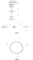
Fig. 2 is a schematic structural diagram showing a thermoelectric generation module according to an exemplary embodiment. -
Fig. 3 is a schematic structural diagram showing an electricity generation unit according to an exemplary embodiment. -
Fig. 4 is a schematic structural diagram showing a thermoelectric generation module according to an exemplary embodiment. -
Fig. 5 is a schematic structural diagram showing a remote control device according to an exemplary embodiment. -
Fig. 6 is a schematic structural diagram showing a remote control device according to an exemplary embodiment. -
Fig. 7 is a schematic structural diagram showing a remote control device according to an exemplary embodiment. - In the drawings, meanings of the reference numbers are as follows: 1. shell; 2. central processor; 3. thermoelectric generation module; 4. button module; 5. RF module; 6. energy storage module; 7. energy indicator; 8. USB interface; 9. Light or jacklight; 10. switch; 31. electricity generation unit; 32. rectification unit; 33. stabilivolt unit; 311. metal sheet of a kind of material; 312. another metal sheet of another kind of material; A. first connection point; and B. second connection point.
- Reference will now be made in detail to exemplary embodiments, examples of which are illustrated in the accompanying drawings. The following description refers to the accompanying drawings in which same reference numbers in different drawings represent same or similar elements unless otherwise described. The implementations set forth in the following description of exemplary embodiments do not represent all implementations consistent with the disclosure. Instead, they are merely examples of devices and methods consistent with aspects related to the disclosure as recited in the appended claims.
- In order to solve the problem of resource waste and environment pollution caused by replacements of the external power supply (such as, a dry battery) for the existing remote control device, a remote control device is provided in the embodiments of the disclosure. The remote control device is based on the Seebeck effect, i.e., a closed loop circuit is formed by connecting two different types of metals; and when the temperatures at two connection points of the closed loop circuit are different, a thermoelectromotive force is generated. Then the remote control device may be powered based on the thermoelectromotive force. Referring to
Fig. 1 , the remote control device may include ashell 1. Theshell 1 is configured with or comprises athermoelectric generation module 3, acentral processor 2, abutton module 4 and a radio frequency (RF)module 5. - The
thermoelectric generation module 3 is connected with each of thecentral processor 2, thebutton module 4 and theRF module 5. Thethermoelectric generation module 3 may supply electric power to the remote control device. Thecentral processor 2 is connected with thebutton module 4 and theRF module 5. Thecentral processor 2 may control operations of each of the function modules of the remote control device. Thebutton module 4 may detect a push-button operation from a user, and send the detected push-button operation to thecentral processor 2. TheRF module 5 may transmit an instruction generated by thecentral processor 2 based on the push-button operation to an appliance paired with the remote control device. - Referring to
Fig. 2 , thethermoelectric generation module 3 may include anelectricity generation unit 31. Referring toFig. 3 , theelectricity generation unit 31 includes twometal sheets metal sheet 311 andmetal sheet 312 may be connected end to end to form a first connection point A and a second connection point B. The first connection point A is positioned within a holding area of the remote control device, while the second connection point B is positioned out of the holding area. Themetal sheet 311 andmetal sheet 312 forms a closed loop circuit via the first connection point A and second connection point B. when a user holds the remote control device, the temperature of the first connection point A becomes higher than the temperature of the second connection point B. When there is a temperature difference between the first connection point A and the second connection point B, theelectricity generation unit 31 may generate a thermoelectromotive force, and power thecentral processor 2, thebutton module 4 and theRF module 5 connected with it utilizing the thermoelectromotive force. - Operating principles of the remote control device when in particular use are as follows.
- When a user wants to use the remote control device to control a paired appliance, the user holds the remote control device, such that the temperature of the first connection point A within the holding area increases and thus become higher than the temperature of the second connection point B. At that moment, a thermoelectromotive force may be generated between the first connection point A and the second connection point B, which may be used to power the
central processor 2, thebutton module 4 and theRF module 5. When thebutton module 4 detects a push-button operation from the user, it sends the detected push-button operation to thecentral processor 2. Thecentral processor 2 generates, according to the button pushed by the user, a corresponding control command, and sends the control command to theRF module 5. TheRF module 5 transmits the control command to the appliance paired with the remote control device, so as to accomplish control of the appliance. - The remote control device provided in the embodiments of the disclosure may use the built-in thermoelectric generation module to power the other function modules without needing an external power supply, such as a dry battery. This solution saves resources and avoids environment pollution, since the electricity is generated based on thermal energy which is pollution free.
- On the basis of structure of the remote control device illustrated in
Fig. 1 , a remote control device is provided in another embodiment of the disclosure. Referring toFig. 4 , the remote control device may further include anenergy storage module 6, which is connected with thethermoelectric generation module 3, thecentral processor 2, thebutton module 4 and theRF module 5. Theenergy storage module 6 may be a storage capacitor with a large capacity. In an embodiment of the disclosure, at the beginning, a user holds the remote control device, thethermoelectric generation module 3 generates a relatively large thermoelectromotive force. A portion of the thermoelectromotive force may be used to supply electric power to the other function modules, and the remaining portion of the thermoelectromotive force may be stored in theenergy storage module 6. With the time duration when the user holds the remote control device becomes longer and longer, the thermoelectromotive force generated by thethermoelectric generation module 3 becomes smaller gradually. When the temperature of the first connection point A is equivalent to the temperature of the second connection point B, thethermoelectric generation module 3 will stop the generation of electric energy, and then the remote control device is powered by theenergy storage module 6. - On the basis of structure of the remote control device illustrated in
Fig. 4 , a remote control device is provided in another embodiment of the disclosure. Referring toFig. 5 , the remote control device may further include anenergy indicator 7, which is connected with theenergy storage module 6. Theenergy indicator 7 has two states of light-up and turn-off. When there is no electric energy stored in theenergy storage module 6, theenergy indicator 7 is turn-off; and when there is electric energy stored in theenergy storage module 6, theenergy indicator 7 is light-up. - On the basis of structure of the remote control device illustrated in
Fig. 5 , a remote control device is provided in another embodiment of the disclosure. Referring toFig. 6 , the remote control device may further include a Universal Serial Bus (USB)interface 8, which is connected with theenergy storage module 6. When a power supply is connected via theUSB interface 8, it may charge theenergy storage module 6. - In order to facilitate push-button operation of a user, the
button module 5 may be further configured with a plurality of buttons. Each of the buttons indicates a function of the remote control device. Each function controls the appliance paired with the remote control device to perform an operation. For example, if the appliance is an intelligent speaker, the button module of the remote control device may be configured with a "switch button", a "state transition button", a "volume adjustment button" and so on. The "switch button" may control the intelligent speaker to be turned on or turned off. The "state transition button" may control the intelligent speaker to transit its state. The "volume adjustment button" may control the intelligent speaker to adjust its volume. - Generally, the electric energy generated by the
thermoelectric generation module 3 is not stable. In order to achieve a steady direct current (DC), thethermoelectric generation module 3 may further include arectification unit 32 and astabilivolt unit 33. The stabilivolt unit is, for example, a gas tube. It maintains a constant voltage drop across its terminals over a wide range of voltages. The voltage drop is largely independent of current. Therectification unit 32 is connected with theelectricity generation unit 31. One end of thestabilivolt unit 33 is connected with therectification unit 32, and the other end of thestabilivolt unit 33 is connected with each of thecentral processor 2, thebutton module 4 and theRF module 5. - In another embodiment of the disclosure, the two metal sheets in the
electricity generation unit 31 may be made of titanium alloys. For example, onemetal sheet 311 is made of the alloy of titanium and a first metal, and theother metal sheet 312 is made of the alloy of titanium and a second metal which is different from the first metal. The two metal sheets in theelectricity generation unit 31 may also be made of aluminium alloys. For example, onemetal sheet 311 is made of the alloy of aluminium and a third metal, and theother metal sheet 312 is made of the alloy of titanium and a fourth metal which is different from the third metal. - In another embodiment of the disclosure, the RF module may be one of a Bluetooth module, a wireless local area network module such as a WiFi (registered trade mark module, an infrared module, and a Near Field Communication (NFC) module. Upon reception of an instruction send by the central processor, the RF module may transmit the instruction to the appliance paired with the remote control device in the form of any one of a Bluetooth signal, a WiFi signal, or an infrared signal; or the RF module may transmit the instruction to the appliance paired with the remote control device by an NFC data channel established with the appliance.
- On the basis of the structure of the remote control device illustrated in
Fig. 5 , a remote control device is provided in another embodiment of the disclosure. Referring toFig. 7 , the remote control device may further include aswitch 10 and a light or j acklight 9. The light 9 is used for lighting. The light 9 is connected with theswitch 10. Theswitch 10 is connected with theenergy storage module 6. In order to facilitate the user to observe the state of theswitch 10, theswitch 10 is configured with two indicators corresponding to an "on" state and an "off' state, respectively. When the user holds the remote control device and turns on theswitch 10, theenergy storage module 6 may power the light to provide lighting for the user. - The remote control device provided in the embodiments of the disclosure may use the built-in thermoelectric generation module to power the other function modules without a need of external power supply, such as a dry battery. This solution saves resources and avoids environment pollution, since the electricity is generated based on thermal energy which is pollution free.
- Other embodiments of the disclosure will be apparent to those skilled in the art from consideration of the specification and practice of the disclosure herein. This application is intended to cover any variations, uses, or adaptations of the disclosure following the general principles thereof and including such departures from the present disclosure as come within known or customary practice in the art. It is intended that the specification and embodiments should be considered as exemplary only, with a true scope of the disclosure being indicated by the following claims.
- It will be appreciated that the inventive concept is not limited to the exact construction that has been described above and illustrated in the accompanying drawings, and that various modifications and changes can be made without departing from the scope thereof. It is intended that the scope of the disclosure only is limited by the appended claims.
Claims (10)
- A remote control device comprising:a shell (1) comprising a thermoelectric generation module (3), a central processor (2), a button module (4) and a radio frequency (RF) module (5), wherein the thermoelectric generation module (3) is connected with each of the central processor (2), the button module (4) and the RF module (5), and the central processor (2) is connected with the button module (4) and the RF module (5);wherein the thermoelectric generation module (3) comprises an electricity generation unit (31), and the electricity generation unit (31) comprises two metal sheets (311 and 312) which are made of different materials and form a closed loop circuit via two connection points (A and B), andwherein the electricity generation unit (31) is able to generate a thermoelectromotive force based on a temperature difference between the two connection points (A and B), and powers the central processor (2), the button module (4) and the RF module (5) by the thermoelectromotive force.
- The remote control device of claim 1, further comprising an energy storage module (6), which is connected with the thermoelectric generation module (3).
- The remote control device of claim 2, wherein the energy storage module (6) is a storage capacitor.
- The remote control device of claim 2 or claim 3, further comprising an energy indicator (7), which is connected with the energy storage module (6) and has two states of light-up and turn-off; wherein
the energy indicator (7) is turn-off when there is no electric energy stored in the energy storage module(6); and
the energy indicator (7) is light-up when there is electric energy stored in the energy storage module(6). - The remote control device according to any preceding claim, further comprising a Universal Serial Bus (USB) interface (8), which is connected with the energy storage module (6).
- The remote control device according to any preceding claim, wherein the button module (4) is configured with a plurality of buttons, each of which indicates a function of the remote control device.
- The remote control device according to any preceding claim, wherein the thermoelectric generation module (3) further comprises a rectification unit (32) and a stabilivolt unit (33), wherein the rectification unit (32) is connected with the electricity generation unit (31), one end of the stabilivolt unit (33) is connected with the rectification unit (32), and the other end of the stabilivolt unit (33) is connected with each of the central processor (2), the button module (4) and the RF module (5).
- The remote control device according to any preceding claim, wherein the two metal sheets (311 and 312) in the electricity generation unit (31) are made of titanium alloys or aluminium alloys.
- The remote control device according to any preceding claim, wherein the RF module (5) comprises one of a Bluetooth (registered trade mark) module, a wireless local area network module such as a WiFi (registered trade mark) module, an infrared module, and a Near Field Communication (NFC) module.
- The remote control device according to any of claims 1 to 4 or claims 5 to 9 when dependent on any of claims 2 to 4, further comprising a switch (10) and a light (9), wherein the light (9) is connected with the switch (10), and the switch (10) is connected with the energy storage module (6).
Applications Claiming Priority (1)
| Application Number | Priority Date | Filing Date | Title |
|---|---|---|---|
| CN201610173310.2A CN105825650A (en) | 2016-03-24 | 2016-03-24 | Remote control device |
Publications (1)
| Publication Number | Publication Date |
|---|---|
| EP3223254A1 true EP3223254A1 (en) | 2017-09-27 |
Family
ID=56524118
Family Applications (1)
| Application Number | Title | Priority Date | Filing Date |
|---|---|---|---|
| EP16200342.0A Withdrawn EP3223254A1 (en) | 2016-03-24 | 2016-11-23 | Remote control device |
Country Status (7)
| Country | Link |
|---|---|
| US (1) | US20170277159A1 (en) |
| EP (1) | EP3223254A1 (en) |
| JP (1) | JP2018513572A (en) |
| KR (1) | KR20170120018A (en) |
| CN (1) | CN105825650A (en) |
| RU (1) | RU2649312C2 (en) |
| WO (1) | WO2017161699A1 (en) |
Families Citing this family (2)
| Publication number | Priority date | Publication date | Assignee | Title |
|---|---|---|---|---|
| CN107152199A (en) * | 2016-10-26 | 2017-09-12 | 廖奕熙 | The key that the ring that can tick prompting is looked for |
| CN108961732A (en) * | 2017-09-26 | 2018-12-07 | 齐鲁工业大学 | Thermoelectric remote control |
Citations (4)
| Publication number | Priority date | Publication date | Assignee | Title |
|---|---|---|---|---|
| EP2333856A2 (en) * | 2009-12-09 | 2011-06-15 | Sony Corporation | Thermoelectric generator, thermoelectric generation method, electrical signal detecting device, and electrical signal detecting method |
| CN204836438U (en) * | 2015-03-13 | 2015-12-02 | 深圳市启悦光电有限公司 | Intelligence TV remote controller with mouse function |
| CN204926483U (en) * | 2015-07-23 | 2015-12-30 | 深圳市不插电科技有限公司 | Learning -oriented infrared remote control of solar charging formula |
| EP2966752A1 (en) * | 2014-07-09 | 2016-01-13 | Paresh Jogia | Body heat powered wireless transmitter |
Family Cites Families (27)
| Publication number | Priority date | Publication date | Assignee | Title |
|---|---|---|---|---|
| JPS57157310A (en) * | 1981-03-24 | 1982-09-28 | Citizen Watch Co Ltd | Power supply circuit for thermo electric generator |
| RU2148803C1 (en) * | 1998-08-31 | 2000-05-10 | Гончаров Владимир Александрович | Heat counter |
| KR20010109852A (en) * | 2000-06-02 | 2001-12-12 | 김태훈 | Gauge auto management system |
| WO2003051477A1 (en) * | 2001-12-14 | 2003-06-26 | Seongho Ko | Dual-function remote controller capable of manipulating video game and method thereof |
| US6990317B2 (en) * | 2002-05-28 | 2006-01-24 | Wireless Innovation | Interference resistant wireless sensor and control system |
| US6967565B2 (en) * | 2003-06-27 | 2005-11-22 | Hx Lifespace, Inc. | Building automation system |
| RU2005115557A (en) * | 2005-05-24 | 2006-11-27 | В чеслав Петрович Хортов (RU) | FLASHLIGHT |
| WO2007098094A2 (en) * | 2006-02-16 | 2007-08-30 | Polacek Denise C | Thermoelectric cooler and reservoir for medical treatment |
| CN200956021Y (en) * | 2006-09-07 | 2007-10-03 | 河海大学 | A thermoelectric effect experimental device |
| TWM325677U (en) * | 2007-02-05 | 2008-01-11 | Sinbon Electronics Company Ltd | Wireless remote-control receiver |
| DE102008037750B3 (en) * | 2008-08-14 | 2010-04-01 | Fm Marketing Gmbh | Method for the remote control of multimedia devices |
| US20110150036A1 (en) * | 2009-12-21 | 2011-06-23 | Electronics And Telecommunications Research Institute | Flexible thermoelectric generator, wireless sensor node including the same and method of manufacturing the same |
| JP5499946B2 (en) * | 2010-06-29 | 2014-05-21 | 富士通株式会社 | Information processing apparatus, information processing method, and computer-readable recording medium storing information processing program |
| US9786159B2 (en) * | 2010-07-23 | 2017-10-10 | Tivo Solutions Inc. | Multi-function remote control device |
| TWM412555U (en) * | 2011-04-26 | 2011-09-21 | Zhong Qian Technology Co Ltd | Infrared learning remote control device |
| US20130087180A1 (en) * | 2011-10-10 | 2013-04-11 | Perpetua Power Source Technologies, Inc. | Wearable thermoelectric generator system |
| WO2014065389A1 (en) * | 2012-10-25 | 2014-05-01 | Semiconductor Energy Laboratory Co., Ltd. | Central control system |
| CN203119801U (en) * | 2013-03-18 | 2013-08-07 | 李雅宁 | Power supply device used for remote controller |
| JP6167660B2 (en) * | 2013-05-13 | 2017-07-26 | 住友電気工業株式会社 | Remote controller and remote control system |
| RU140225U1 (en) * | 2013-05-23 | 2014-05-10 | Федеральное государственное бюджетное образовательное учреждение высшего профессионального образования "Владимирский государственный университет имени Александра Григорьевича и Николая Григорьевича Столетовых" (ВлГУ) | HEAT METER FOR HOT WATER SUPPLY SYSTEMS |
| US20150137994A1 (en) * | 2013-10-27 | 2015-05-21 | Aliphcom | Data-capable band management in an autonomous advisory application and network communication data environment |
| CN103734937A (en) * | 2013-12-11 | 2014-04-23 | 中山市永衡日用制品有限公司 | Intelligent wristband with body temperature power generation and power supply function |
| JP2015225610A (en) * | 2014-05-29 | 2015-12-14 | 大和ハウス工業株式会社 | Information notification system and information notification method |
| CN204465413U (en) * | 2015-03-31 | 2015-07-08 | 段科 | A kind of wearable device charger based on solar energy, body temperature generating |
| CN204536410U (en) * | 2015-05-08 | 2015-08-05 | 深圳市尼索电子科技有限公司 | For body temperature generating and the electricity generation situation supervisory circuit of Intelligent worn device |
| CN104852635A (en) * | 2015-06-02 | 2015-08-19 | 广州成科信息科技有限公司 | Method for thermoelectric generator to supply power to sensing equipment |
| CN105243825A (en) * | 2015-10-29 | 2016-01-13 | 桂林市腾瑞电子科技有限公司 | Multifunctional remote controller |
-
2016
- 2016-03-24 CN CN201610173310.2A patent/CN105825650A/en active Pending
- 2016-06-06 JP JP2016548047A patent/JP2018513572A/en active Pending
- 2016-06-06 KR KR1020167020688A patent/KR20170120018A/en not_active Ceased
- 2016-06-06 WO PCT/CN2016/085019 patent/WO2017161699A1/en not_active Ceased
- 2016-06-06 RU RU2016130872A patent/RU2649312C2/en active
- 2016-11-23 EP EP16200342.0A patent/EP3223254A1/en not_active Withdrawn
-
2017
- 2017-03-16 US US15/460,343 patent/US20170277159A1/en not_active Abandoned
Patent Citations (4)
| Publication number | Priority date | Publication date | Assignee | Title |
|---|---|---|---|---|
| EP2333856A2 (en) * | 2009-12-09 | 2011-06-15 | Sony Corporation | Thermoelectric generator, thermoelectric generation method, electrical signal detecting device, and electrical signal detecting method |
| EP2966752A1 (en) * | 2014-07-09 | 2016-01-13 | Paresh Jogia | Body heat powered wireless transmitter |
| CN204836438U (en) * | 2015-03-13 | 2015-12-02 | 深圳市启悦光电有限公司 | Intelligence TV remote controller with mouse function |
| CN204926483U (en) * | 2015-07-23 | 2015-12-30 | 深圳市不插电科技有限公司 | Learning -oriented infrared remote control of solar charging formula |
Also Published As
| Publication number | Publication date |
|---|---|
| JP2018513572A (en) | 2018-05-24 |
| WO2017161699A1 (en) | 2017-09-28 |
| KR20170120018A (en) | 2017-10-30 |
| RU2649312C2 (en) | 2018-04-02 |
| RU2016130872A (en) | 2018-01-31 |
| US20170277159A1 (en) | 2017-09-28 |
| CN105825650A (en) | 2016-08-03 |
Similar Documents
| Publication | Publication Date | Title |
|---|---|---|
| KR102423599B1 (en) | Wireless power transmitter and method for controlling the same | |
| CN105515617B (en) | Apparatus and method for transmitting/receiving PTU presence information in wireless charging network | |
| KR102028455B1 (en) | Wireless power transmitter, wireless power receiver and method for controlling each thereof | |
| JP2019022450A (en) | Wireless power transmitter and method for controlling the same | |
| JP2009112155A (en) | Remote power control system and power strip | |
| CN107018610A (en) | Single live wire intelligent switch | |
| JP6116832B2 (en) | Contactless charging system | |
| US20160344230A1 (en) | Charging management apparatus, charging apparatus, and charging management method | |
| CN104914834A (en) | Household electrical appliance control method, household electrical appliance control device and terminal | |
| US8847775B2 (en) | Tangible charge level awareness method and apparatus using augmented batteries | |
| JP2015208132A (en) | Electric vehicle charge/discharge apparatus | |
| EP3223254A1 (en) | Remote control device | |
| JP2015115930A (en) | Self power generation type radio communication device, radio communication system, and information transmission and reception method | |
| JP5837551B2 (en) | Sensor system | |
| CN203933166U (en) | Wireless charging generation circuit and home appliances | |
| CN205158606U (en) | Intelligent remote control device | |
| JP2005223541A (en) | Communication adapter receiving power supply from electrical equipment and communication adapter receiving power supply from air conditioner indoor unit | |
| JP2018521623A (en) | Wireless power transmission method in wireless charging system including wireless power transmitter and wireless power receiver | |
| WO2013185700A1 (en) | Mobile terminal and charging apparatus for same | |
| CN208571721U (en) | A mobile power wireless charging and discharging system | |
| JP2002095067A (en) | Remote control system | |
| CN206685640U (en) | A plug-in strip with power storage and wireless charging functions | |
| CN218526234U (en) | Outdoor power supply device capable of switching DC output and AC output | |
| CN208849472U (en) | Wireless charging system | |
| CN203933167U (en) | Wireless charging receiving circuit and portable rechargeable device |
Legal Events
| Date | Code | Title | Description |
|---|---|---|---|
| PUAI | Public reference made under article 153(3) epc to a published international application that has entered the european phase |
Free format text: ORIGINAL CODE: 0009012 |
|
| AK | Designated contracting states |
Kind code of ref document: A1 Designated state(s): AL AT BE BG CH CY CZ DE DK EE ES FI FR GB GR HR HU IE IS IT LI LT LU LV MC MK MT NL NO PL PT RO RS SE SI SK SM TR |
|
| AX | Request for extension of the european patent |
Extension state: BA ME |
|
| 17P | Request for examination filed |
Effective date: 20180322 |
|
| RBV | Designated contracting states (corrected) |
Designated state(s): AL AT BE BG CH CY CZ DE DK EE ES FI FR GB GR HR HU IE IS IT LI LT LU LV MC MK MT NL NO PL PT RO RS SE SI SK SM TR |
|
| 17Q | First examination report despatched |
Effective date: 20180627 |
|
| STAA | Information on the status of an ep patent application or granted ep patent |
Free format text: STATUS: THE APPLICATION HAS BEEN WITHDRAWN |
|
| 18W | Application withdrawn |
Effective date: 20180913 |