EP3223138A2 - Print control device, method and program - Google Patents
Print control device, method and program Download PDFInfo
- Publication number
- EP3223138A2 EP3223138A2 EP16187441.7A EP16187441A EP3223138A2 EP 3223138 A2 EP3223138 A2 EP 3223138A2 EP 16187441 A EP16187441 A EP 16187441A EP 3223138 A2 EP3223138 A2 EP 3223138A2
- Authority
- EP
- European Patent Office
- Prior art keywords
- unit
- instruction
- data
- job
- Prior art date
- Legal status (The legal status is an assumption and is not a legal conclusion. Google has not performed a legal analysis and makes no representation as to the accuracy of the status listed.)
- Granted
Links
Images




Classifications
-
- G—PHYSICS
- G06—COMPUTING OR CALCULATING; COUNTING
- G06F—ELECTRIC DIGITAL DATA PROCESSING
- G06F3/00—Input arrangements for transferring data to be processed into a form capable of being handled by the computer; Output arrangements for transferring data from processing unit to output unit, e.g. interface arrangements
- G06F3/12—Digital output to print unit, e.g. line printer, chain printer
- G06F3/1201—Dedicated interfaces to print systems
- G06F3/1202—Dedicated interfaces to print systems specifically adapted to achieve a particular effect
- G06F3/1203—Improving or facilitating administration, e.g. print management
-
- G—PHYSICS
- G06—COMPUTING OR CALCULATING; COUNTING
- G06K—GRAPHICAL DATA READING; PRESENTATION OF DATA; RECORD CARRIERS; HANDLING RECORD CARRIERS
- G06K15/00—Arrangements for producing a permanent visual presentation of the output data, e.g. computer output printers
- G06K15/40—Details not directly involved in printing, e.g. machine management, management of the arrangement as a whole or of its constitutive parts
- G06K15/408—Handling exceptions, e.g. faults
- G06K15/409—Handling power failures
-
- G—PHYSICS
- G06—COMPUTING OR CALCULATING; COUNTING
- G06F—ELECTRIC DIGITAL DATA PROCESSING
- G06F3/00—Input arrangements for transferring data to be processed into a form capable of being handled by the computer; Output arrangements for transferring data from processing unit to output unit, e.g. interface arrangements
- G06F3/12—Digital output to print unit, e.g. line printer, chain printer
- G06F3/1201—Dedicated interfaces to print systems
- G06F3/1202—Dedicated interfaces to print systems specifically adapted to achieve a particular effect
- G06F3/1211—Improving printing performance
-
- G—PHYSICS
- G06—COMPUTING OR CALCULATING; COUNTING
- G06F—ELECTRIC DIGITAL DATA PROCESSING
- G06F3/00—Input arrangements for transferring data to be processed into a form capable of being handled by the computer; Output arrangements for transferring data from processing unit to output unit, e.g. interface arrangements
- G06F3/12—Digital output to print unit, e.g. line printer, chain printer
- G06F3/1201—Dedicated interfaces to print systems
- G06F3/1223—Dedicated interfaces to print systems specifically adapted to use a particular technique
- G06F3/1229—Printer resources management or printer maintenance, e.g. device status, power levels
-
- G—PHYSICS
- G06—COMPUTING OR CALCULATING; COUNTING
- G06F—ELECTRIC DIGITAL DATA PROCESSING
- G06F3/00—Input arrangements for transferring data to be processed into a form capable of being handled by the computer; Output arrangements for transferring data from processing unit to output unit, e.g. interface arrangements
- G06F3/12—Digital output to print unit, e.g. line printer, chain printer
- G06F3/1201—Dedicated interfaces to print systems
- G06F3/1223—Dedicated interfaces to print systems specifically adapted to use a particular technique
- G06F3/1237—Print job management
- G06F3/1273—Print job history, e.g. logging, accounting, tracking
-
- G—PHYSICS
- G06—COMPUTING OR CALCULATING; COUNTING
- G06F—ELECTRIC DIGITAL DATA PROCESSING
- G06F3/00—Input arrangements for transferring data to be processed into a form capable of being handled by the computer; Output arrangements for transferring data from processing unit to output unit, e.g. interface arrangements
- G06F3/12—Digital output to print unit, e.g. line printer, chain printer
- G06F3/1201—Dedicated interfaces to print systems
- G06F3/1278—Dedicated interfaces to print systems specifically adapted to adopt a particular infrastructure
- G06F3/1282—High volume printer device
-
- G—PHYSICS
- G06—COMPUTING OR CALCULATING; COUNTING
- G06K—GRAPHICAL DATA READING; PRESENTATION OF DATA; RECORD CARRIERS; HANDLING RECORD CARRIERS
- G06K15/00—Arrangements for producing a permanent visual presentation of the output data, e.g. computer output printers
- G06K15/02—Arrangements for producing a permanent visual presentation of the output data, e.g. computer output printers using printers
- G06K15/18—Conditioning data for presenting it to the physical printing elements
- G06K15/1801—Input data handling means
- G06K15/1803—Receiving particular commands
- G06K15/1806—Receiving job control commands
- G06K15/1807—Receiving job control commands relating to the print image preparation
-
- G—PHYSICS
- G06—COMPUTING OR CALCULATING; COUNTING
- G06K—GRAPHICAL DATA READING; PRESENTATION OF DATA; RECORD CARRIERS; HANDLING RECORD CARRIERS
- G06K15/00—Arrangements for producing a permanent visual presentation of the output data, e.g. computer output printers
- G06K15/02—Arrangements for producing a permanent visual presentation of the output data, e.g. computer output printers using printers
- G06K15/18—Conditioning data for presenting it to the physical printing elements
- G06K15/1835—Transforming generic data
- G06K15/1836—Rasterization
-
- G—PHYSICS
- G06—COMPUTING OR CALCULATING; COUNTING
- G06K—GRAPHICAL DATA READING; PRESENTATION OF DATA; RECORD CARRIERS; HANDLING RECORD CARRIERS
- G06K15/00—Arrangements for producing a permanent visual presentation of the output data, e.g. computer output printers
- G06K15/02—Arrangements for producing a permanent visual presentation of the output data, e.g. computer output printers using printers
- G06K15/18—Conditioning data for presenting it to the physical printing elements
- G06K15/1848—Generation of the printable image
- G06K15/1849—Generation of the printable image using an intermediate representation, e.g. a list of graphical primitives
-
- Y—GENERAL TAGGING OF NEW TECHNOLOGICAL DEVELOPMENTS; GENERAL TAGGING OF CROSS-SECTIONAL TECHNOLOGIES SPANNING OVER SEVERAL SECTIONS OF THE IPC; TECHNICAL SUBJECTS COVERED BY FORMER USPC CROSS-REFERENCE ART COLLECTIONS [XRACs] AND DIGESTS
- Y02—TECHNOLOGIES OR APPLICATIONS FOR MITIGATION OR ADAPTATION AGAINST CLIMATE CHANGE
- Y02D—CLIMATE CHANGE MITIGATION TECHNOLOGIES IN INFORMATION AND COMMUNICATION TECHNOLOGIES [ICT], I.E. INFORMATION AND COMMUNICATION TECHNOLOGIES AIMING AT THE REDUCTION OF THEIR OWN ENERGY USE
- Y02D10/00—Energy efficient computing, e.g. low power processors, power management or thermal management
Definitions
- the present invention relates to a print control device and a program.
- JP-A-8-263349 there is disclosed a data management system in which update information data is written to plural update record storage devices to provide redundancy when updating data in a storage device, the update information data is read from a designated update record storage device to restore data of a predetermined time point when restoring data to thereby improve reliability of data integrity in the event of failures of the storage device and the update record storage device.
- JP-A-9-244933 there is disclosed a database backup method in which data guaranteed by a recovery process from a secondary memory is stored in a guarantee area in different areas on a main memory in respective records, columns, and combinations of records and columns, non-guaranteed data is stored in a non-guarantee area for respective guarantee types, and only the data guaranteed by the recovery process is backed up to the secondary memory.
- JP-A-2010-128808 there is disclosed a storage control device having a battery-backed-up storage device obtained by integrating a cache memory of a storage device and a CPU-side system memory in which an ASIC having a virtual window function is added to a system, and I/Os of a front-end and a back-end are performed via the virtual window to thereby perform addition of data integrity codes and automated dual write of data.
- a method of storing various items of information automatically such as a method of storing various items of information in the volatile memory in execution of a print process in a nonvolatile memory periodically is sometimes used.
- a process of storing the information in the volatile memory in the nonvolatile memory is performed frequently, the original print processing performance may deteriorate.
- an acceptable range of deterioration of the print processing performance is narrow and it is desirable to reduce the deterioration of the print processing performance as much as possible.
- An object of the present invention is to provide a print control device and a program capable of allowing a system to restore to the original state even when an unexpected power interruption occurs while reducing an adverse effect on the printing performance as compared to a case in which various items of information generated when print control is executed based on a print instruction are automatically stored in a nonvolatile memory.
- a first aspect of the invention provides a print control device including a management unit that receives and manages an instruction to execute processing, a processing unit that performs processing based on the instruction that is received, and a storage unit that stores an attribute information indicating an attribution of the instruction stored by the management unit and state information indicating a processing state of the processing unit in a nonvolatile storing unit using resources of the processing unit when processing based on the instruction is not executed.
- a second aspect of the invention provides a print control device including a management unit that receives and manages a print instruction, a generation unit that generates a print data of an intermediate format based on the print instruction that is received, a conversion unit that converts the print data of an intermediate format generated by the generation unit to an output image data, a print controller that controls a printing device based on the output image data converted by the conversion unit, and a storage unit that stores an attribute information indicating an attribution of the print instruction stored by the management unit and history information indicating a processing state of the print instruction stored by the generation unit and the conversion unit in a nonvolatile storing unit using resources of the generation unit and the conversion unit when a print process based on the print instruction is not executed.
- a third aspect of the invention provides a print control device including a management unit that receives and manages a print instruction, a generation unit that generates a print data of an intermediate format based on the print instruction that is received, a conversion unit that converts the print data of an intermediate format generated by the generation unit to an output image data, a print controller that controls a printing device based on the output image data converted by the conversion unit, and a storage unit that stores an attribute information indicating an attribution of the print instruction stored by the management unit and history information indicating a processing state of the print instruction stored by the generation unit and the conversion unit in a nonvolatile storing unit using resources of the generation unit and the conversion unit when a print process based on the print instruction is not executed and the print data of the intermediate format is not generated by the generation unit.
- a case that the print process based on the print instruction is not executed includes a case that a converting process to convert the print data of the intermediate format to the output image data is not performed by the conversion unit and print control on the printing device is not performed by the print controller.
- a fifth aspect of the invention provides a print control device including a management unit that receives and manages a print instruction, a generation unit that generates a print data of an intermediate format based on the print instruction that is received, a conversion unit that converts the print data of an intermediate format generated by the generation unit to an output image data, a print controller that controls a printing device based on the output image data converted by the conversion unit, and a storage unit that stores an attribute information indicating an attribution of the print instruction stored by the management unit and history information indicating a processing state of the print instruction stored by the generation unit and the conversion unit in a nonvolatile storing unit using resources of the generation unit and the conversion unit when a state is maintained for a preset period, wherein the state is a state that after a print process based on the print instruction is performed, a subsequent print process based on a subsequent print instruction is not started.
- a sixth aspect of the invention provides a print control device including a management unit that receives and manages a print instruction, a generation unit that generates a print data of an intermediate format based on the print instruction that is received, a conversion unit that converts the print data of an intermediate format generated by the generation unit to an output image data, a print controller that controls a printing device based on the output image data converted by the conversion unit, and a storage unit that stores an attribute information indicating an attribution of the print instruction stored by the management unit and history information indicating a processing state of the print instruction stored by the generation unit and the conversion unit in a nonvolatile storing unit using resources of the generation unit and the conversion unit when a state that a print process based on a print instruction is not started, is continued for a preset period.
- the history information includes a first control information indicating a processing state of a print instruction in the generation unit, a second control information indicating a processing state of the print instruction in the conversion unit, a first management information to manage the print data of the intermediate format that is generated, and a second management information to manage the output image data that is converted.
- a eighth aspect of the invention provides a control method for a printing device, the control method includes receiving and managing an instruction to execute processing, performing processing based on the instruction that is received; and storing an attribute information indicating an attribution of the instruction stored by the management unit and state information indicating a processing state of the processing unit in a nonvolatile storing unit using resources of the processing unit when processing based on the instruction is not executed.
- a ninth aspect of the invention provides a program causing a computer to execute a process for controlling a print data, the process is provided with receiving and managing a print instruction, generating the print data of an intermediate format based on the print instruction that is received, converting the print data of the intermediate format to an output image data, controlling a printing device based on the image data, and storing an attribute information indicating an attribution of the print instruction and history information indicating a processing state of the print instruction in a nonvolatile storing unit using resources of a generation unit that generates the print data of the intermediate format and the conversion unit that converts the print data of the intermediate format to the output image data when a print process based on the print instruction is not executed.
- the first aspect of the present invention it is possible to provide a print control device capable of allowing a system to restore to the original state even when an unexpected power interruption occurs while reducing an adverse effect on the printing performance as compared to a case in which various items of information generated when print control is executed based on a print instruction are automatically stored in a nonvolatile memory.
- the second aspect of the present invention it is possible to provide a print control device capable of allowing a system to restore to the original state even when an unexpected power interruption occurs while reducing an adverse effect on the printing performance as compared to a case in which various items of information generated when print control is executed based on a print instruction are automatically stored in a nonvolatile memory.
- the third aspect of the present invention it is possible to provide a print control device capable of allowing a system to restore to the original state even when an unexpected power interruption occurs while reducing an adverse effect on the printing performance as compared to a case in which various items of information generated when print control is executed based on a print instruction are automatically stored in a nonvolatile memory.
- a print control device capable of allowing a system to restore to the original state even when an unexpected power interruption occurs while reducing an adverse effect on the printing performance as compared to a case in which various items of information generated when print control is executed based on a print instruction are automatically stored in a nonvolatile memory.
- the fifth aspect of the present invention it is possible to provide a print control device capable of allowing a system to restore to the original state even when an unexpected power interruption occurs while reducing an adverse effect on the printing performance as compared to a case in which various items of information generated when print control is executed based on a print instruction are automatically stored in a nonvolatile memory.
- a print control device capable of allowing a system to restore to the original state even when an unexpected power interruption occurs while reducing an adverse effect on the printing performance as compared to a case in which various items of information generated when print control is executed based on a print instruction are automatically stored in a nonvolatile memory.
- the seventh aspect of the present invention it is possible to provide a print control device capable of allowing a system to restore to the original state even when an unexpected power interruption occurs while reducing an adverse effect on the printing performance as compared to a case in which various items of information generated when print control is executed based on a print instruction are automatically stored in a nonvolatile memory.
- the eighth aspect of the present invention it is possible to provide a method capable of allowing a system to restore to the original state even when an unexpected power interruption occurs while reducing an adverse effect on the printing performance as compared to a case in which various items of information generated when print control is executed based on a print instruction are automatically stored in a nonvolatile memory.
- the ninth aspect of the present invention it is possible to provide a program capable of allowing a system to restore to the original state even when an unexpected power interruption occurs while reducing an adverse effect on the printing performance as compared to a case in which various items of information generated when print control is executed based on a print instruction are automatically stored in a nonvolatile memory.
- Fig. 1 is a diagram illustrating an instance of a configuration of a printing system according to an exemplary embodiment of the present invention. As illustrated in Fig. 1 , this printing system includes a printing device 30 that performs printing on a continuous sheet, a controller (print control device) 10, and a terminal device 20.
- the terminal device 20 generates a print instruction such as a print job and transmits the print instruction to the controller 10 via a network.
- the controller 10 functions as a print control device that controls a print operation of the printing device 30 according to the print instruction transmitted from the terminal device 20.
- the printing device 30 outputs an image corresponding to the print instruction on a continuous sheet based on the control of the controller 10.
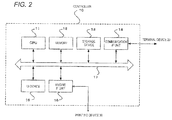
- the controller 10 of the present exemplary embodiment includes a CPU 11, a memory 12, a storage device 13 such as a hard disk drive (HDD), a communication interface (IF) unit 14 that transmits and receives data to and from the terminal device 20 via a network, a user interface (UI) device 15 configured with a touch panel or a liquid crystal display, and an engine IF unit 16 that transmits and receives data to and from the printing device 30.
- a control bus 17 a control bus 17
- the CPU 11 executes a predetermined process based on a print control program stored in the memory 12 or the storage device 13 and controls the operation of the controller 10.
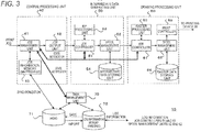
- Fig. 3 is a block diagram illustrating a functional configuration of the controller 10 which is realized by the execution of the control program.
- the controller 10 of the present exemplary embodiment includes a central processing unit 40, an intermediate data generating unit 50, a drawing processing unit 60, a task management unit 70, an HDD 71 which is a nonvolatile memory, and a log information memory 72 such as a RAM disc.
- the central processing unit 40 includes a job management unit 41, a job output unit 42, and a job information memory 43.
- the intermediate data generating unit 50 includes a job controller 51, a spool management unit 52, a raster image processing (RIP) processing unit 53, and an intermediate data storing unit 54.
- RIP raster image processing
- the drawing processing unit 60 includes a job controller 61, a spool management unit 62, a raster processing unit 63, a raster data storing unit 64, and a print controller 65.
- the task management unit 70 performs overall internal management of the system such as the activation and shutdown process of the entire system, control such as activation and shutdown of internal modules associated with this process, state management of the entire system, priority setting of respective modules, management of CPU cores, and adjustment during collection of log information.
- a print job (print instruction) described in a page description language, transmitted from the terminal device 20 via a network is first registered in the job management unit 41 of the central processing unit 40.
- the job management unit 41 is a management unit that receives and manages the transmitted print job.
- the job management unit 41 manages the state of the registered print job and executes or removes the registered print job based on an instruction from a user interface (UI) or the like.
- UI user interface
- the job management unit 41 receives a notification of an execution state of the print job from the job controller 51 of the intermediate data generating unit 50 and the job controller 61 of the drawing processing unit 60 to update the execution state of the print job.
- the job management unit 41 stores job information (attribute information) indicating the attribute of a print job, such as a job ID (identifier) of the print job, a file name, and various items of setting information such as the number of pages in the job information memory 43.
- job information attribute information indicating the attribute of a print job, such as a job ID (identifier) of the print job, a file name, and various items of setting information such as the number of pages in the job information memory 43.
- the job information memory 43 stores the job information in a file format called a mapped file (memory-mapped file).
- This mapped file is a storage method of mapping and storing file data directly onto a continuous area of a virtual storage space. According to this method, the job information stored in the HDD 71 in a file format is used as a resource and the information having the same content as the job information stored in the HDD 71 is stored in the job information memory 43.
- the job management unit 41 updates the job information in the job information memory 43
- the job information in the HDD 71 has a different content from the job information in the job information memory 43 unless predetermined processing is performed.
- the job management unit 41 executes a synchronization process for making the job information in the HDD 71 identical to the job information in the job information memory 43.
- this synchronization process is executed, the job information in the HDD 71 has the same content as the job information in the job information memory 43.
- the job output unit 42 transmits the print job to the intermediate data generating unit 50 in respective pages based on the control of the job management unit 41.
- the intermediate data generating unit 50 generates intermediate data (print data of an intermediate format) based on the print job received by the central processing unit 40.
- the drawing processing unit 60 converts the intermediate data generated by the intermediate data generating unit 50 to raster data (image data of a raster format).
- the print controller 65 controls the printing device 30 based on the image data converted by the drawing processing unit 60.
- the image data of the raster format is an instance of image data for drawing and image data of another format may be used as the image data for drawing.
- the intermediate data generating unit 50 transmits the print job transmitted in respective pages from the central processing unit 40 to the RIP processing unit 53 so that the print job is subjected to a RIP process to thereby generate intermediate data (print data of an intermediate format).
- the spool management unit 52 stores the intermediate data generated by the RIP processing unit 53 in the intermediate data storing unit 54 as spool data and manages the intermediate data.
- the job controller 61 of the drawing processing unit 60 executes a raster process on the transmitted intermediate data with the aid of the raster processing unit 63 to convert the intermediate data to image data of a raster format.
- the spool management unit 62 of the drawing processing unit 60 stores the image data of the raster format converted by the raster processing unit 63 in the raster data storing unit 64 as spool data and manages the image data.
- the drawing processing unit 60 Upon receiving an instruction to execute a print process from the job management unit 41, the drawing processing unit 60 allows the print controller 65 to transmit the image data of the raster format to the printing device 30 in respective pages so that a print process is executed based on the image data.
- the print controller 65 may be configured to be independent from the drawing processing unit 60.
- the job controller 51 notifies the job management unit 41 of a state whether a RIP process is being executed by the intermediate data generating unit 50.
- the job controller 61 notifies the job management unit 41 of a state whether a raster process is being executed by the drawing processing unit 60.
- the job management unit 41 sends the state notification received from the job controllers 51 and 61 to the task management unit 70 so that the task management unit 70 can understand the state of the entire system. Specifically, based on the state notification from the job management unit 41, the task management unit 70 can understand whether the RIP process is being executed by the RIP processing unit 53 of the intermediate data generating unit 50 and whether the raster process is being executed by the raster processing unit 63 of the drawing processing unit 60.
- the log information memory 72 mainly stores log information (history information) indicating the print stop state of a print job when various processes are executed by the job controllers 51 and 61 and the spool management units 52 and 62.
- the log information memory 72 also stores operation logs of the other modules.
- the log information memory 72 is configured as a so-called RAM disc that realizes the same storage device as a disk drive such as a HDD using a volatile memory. The details of the log information will be described below.
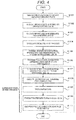
- step S101 When the job output unit 42 of the central processing unit 40 transmits a print job to the intermediate data generating unit 50 in respective pages (step S101) and the job management unit 41 issues an instruction to execute a RIP process to the job controller 51 (step S102), the RIP processing unit 53 in the intermediate data generating unit 50 executes a RIP process to generate intermediate data (step S103).
- the generated intermediate data is stored in the intermediate data storing unit 54 as spool data, and the spool management unit 52 manages the stored intermediate data (step S104).
- step S105 When the intermediate data is transmitted from the intermediate data generating unit 50 to the drawing processing unit 60 (step S105) and an output instruction is transmitted from the job management unit 41 to the job controller 61 (step S106), the job controller 61 notifies the job management unit 41 of the start of a print process and the job management unit 41 notifies the task management unit 70 of the start of printing (step S107).
- the raster processing unit 63 executes a raster process on the intermediate data (step S108) and the raster data is stored in the raster data storing unit 64 and is managed by the spool management unit 62 (step S109).
- the print controller 65 transmits the spooled raster data to the printing device 30 and executes a print process (step S110).
- the print controller 65 executes the print process until there is no raster data of a page to be printed and ends the print process when there is no page data to be printed (step Sill).
- the job controller 61 notifies the job management unit 41 of the end of the print process and the job management unit 41 notifies the task management unit 70 of the end of the print process.
- a period until the job management unit 41 notifies the task management unit 70 of the end of the print process after the job management unit 41 notifies the task management unit 70 of the start of printing is a period in which it is determined that the task management unit 70 is under execution of the print process.
- job information indicating the attribute of a print job and log information necessary for the control of the intermediate data generating unit 50 and the drawing processing unit 60 are stored in the job information memory 43 and the log information memory 72 and are used.
- the job information memory 43 and the log information memory 72 are configured with volatile memories and power is interrupted, the contents stored therein may be deleted.
- the job management unit 41 and the task management unit 70 execute a process of storing these items of information in the HDD 71 which is a nonvolatile storage unit before the shutdown.
- the job management unit 41 when the system is shut down, the job management unit 41 performs a synchronization process of synchronizing the job information stored in the job information memory 43 with the job information stored in the HDD 71. Moreover, the task management unit 70 performs a process of saving the log information stored in the log information memory 72 in the HDD 71.
- the job management unit 41 and the task management unit 70 execute synchronization of the job information in the job information memory 43 and saving of the log information in the log information memory 72 in cases other than the normal power interruption.
- the job information synchronization process and the log information saving process will be collectively referred to as a data storage process.
- this data storage process will be described.
- the job management unit 41 stores the job information stored in the job information memory 43 in the HDD 71 and the task management unit 70 stores the log information (history information) used in the intermediate data generating unit 50 and the drawing processing unit 60 in the HDD 71.
- the log information includes job control information which is used in the job controller 51 of the intermediate data generating unit 50 and indicates the processing state of a print job being processed, job control information which is used in the job controller 61 of the drawing processing unit 60 and indicates the processing state of a print job being processed, data management information for managing the intermediate data stored in the intermediate data storing unit 54 of the spool management unit 52, and data management information for managing the raster data stored in the raster data storing unit 64 of the spool management unit 62.
- the job control information is information indicating the processing state of a print job being processed such as information indicating to which page processing has been executed.
- the data management information is information indicating a storage location or the like in which the intermediate data storing unit 54 and the raster data storing unit 64 store the intermediate data and the raster data.
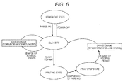
- the controller 10 performs transition between four states including a power-off state, an idle state (standby state), a printing state, and a print stop state as a basic operation state.
- the job management unit 41 and the task management unit 70 of the present exemplary embodiment store the job information stored in the job information memory 43 and the log information stored by the job controller 51 of the intermediate data generating unit 50 and the job controller 61 of the drawing processing unit 60 in the HDD 71 using the resources of the intermediate data generating unit 50 and the drawing processing unit 60 in a state other than the print stop state, which is a state in which a print process based on a print job is not executed.
- the print stop state which is a state in which a print process based on a print job is not executed.
- a case in which the print process based on a print job is not executed is a case other than a print process execution state indicated in the flowchart of Fig. 4 and is a case in which the raster processing unit 63 of the drawing processing unit 60 is not performing a process of converting image data to raster data and the print controller 65 is not performing print control on the printing device 30.
- the resources of the intermediate data generating unit 50 and the drawing processing unit 60 used when the job management unit 41 and the task management unit 70 store the job information and the log information in the HDD 71 means various resources for executing processes, specifically such as the processing performance of the CPU and the memory capacity of RAM. For instance, when the controller 10 is controlled by one CPU, the processing performance of the CPU is consumed by various modules including the central processing unit 40, the intermediate data generating unit 50, and the drawing processing unit 60.
- the job management unit 41 and the task management unit 70 execute the process of storing the job information and the log information using the resources used when the intermediate data generating unit 50 and the drawing processing unit 60 execute processes since the intermediate data generating unit 50 and the drawing processing unit 60 are not executing processes.
- a basic state transition of the controller 10 will be described with reference to the diagram illustrated in Fig. 6 .
- the state of the controller 10 transitions from a power-off state to an idle state in response to a power-on event in which power is supplied. Moreover, when a power-off operation is performed in the idle state, the controller 10 enters into the power-off state.
- a print job is received in the idle state and a print instruction is received, printing starts and the controller 10 enters into a printing state.
- the controller 10 enters into the print stop state.
- the job management unit 41 and the task management unit 70 store the job information stored in the job information memory 43 and the log information stored by the job controller 51 of the intermediate data generating unit 50 and the job controller 61 of the drawing processing unit 60 in the HDD 71.
- the job management unit 41 performs a process of synchronizing the job information stored in the job information memory 43 and the task management unit 70 saves the log information stored by the job controller 51 of the intermediate data generating unit 50 and the job controller 61 of the drawing processing unit 60 in the HDD 71.
- the controller 10 After the data storage process ends, the controller 10 enters to the idle state.
- the job management unit 41 and the task management unit 70 stores the job information stored in the job information memory 43 and the log information stored by the job controller 51 of the intermediate data generating unit 50 and the job controller 61 of the drawing processing unit 60 in the HDD 71.
- the job management unit 41 performs a process of synchronizing the job information stored in the job information memory 43 and the task management unit 70 saves the log information stored by the job controller 51 of the intermediate data generating unit 50 and the job controller 61 of the drawing processing unit 60 in the HDD 71.
- the job management unit 41 and the task management unit 70 repeat the process of storing the job information and the log information every one hour.
- step S201 When raster data is generated in the drawing processing unit 60 and the raster data generated by the print controller 65 is transmitted to the printing device 30 whereby a print process is executed (step S201) and the print process is completed (step S202), the job management unit 41 and the task management unit 70 store a time stamp (time information) indicating the printing completion time (step S203).
- step S204 when the time elapsed from the completion of printing exceeds a preset interval period, the job management unit 41 and the task management unit 70 execute the process of storing the job information and the log information (step S205).
- the job management unit 41 and the task management unit 70 store a new time stamp indicating the time when the data storage process is executed (step S206).
- the job management unit 41 and the task management unit 70 measure the time for executing various processes using an idle timer that times-out every predetermined period in the idle state.
- the job management unit 41 and the task management unit 70 initialize the idle timer (step S301).
- step S302 the job management unit 41 and the task management unit 70 compare a stored time stamp with a present time stamp to measure the time elapsed from the previous data storage process (step S303).
- step S304 no
- the job management unit 41 and the task management unit 70 initialize the idle time again and repeat processes (step S301).
- step S304 When the time elapsed from the previous data storage process exceeds the preset interval period (step S304: yes), the job management unit 41 and the task management unit 70 check whether a print process is being executed (step S305) and execute the process of storing the job information and the log information (step S306).
- the job management unit 41 and the task management unit 70 store a new time stamp indicating the time when the data storage process is executed and returns to the process of step S301 (step S307).
- the job management unit 41 and the task management unit 70 execute the process of storing the job information and the log information whenever the idle timer times out 60 times.
- the idle state includes a state (RIP processing state) in which the intermediate data generating unit 50 performs a process of generating intermediate data based on a print job and spooling the intermediate data only and the drawing processing unit 60 does not perform a print process
- the RIP processing state may be an independent state which is not included in the idle state.
- a state in which the intermediate data generating unit 50 performs a process of generating intermediate data based on a print job and spooling the intermediate data may be regarded as a RIP processing state.
- the controller enters into the RIP processing state when a RIP process starts in the idle state and enters into the idle state when the RIP process is completed.
- the job management unit 41 and the task management unit 70 may store the job information stored in the job information memory 43 and the log information stored by the job controller 51 of the intermediate data generating unit 50 and the job controller 61 of the drawing processing unit 60 in the HDD 71 when a print process based on a print job is not executed and the intermediate data generating unit 50 is not generating intermediate data.
Landscapes
- Engineering & Computer Science (AREA)
- Theoretical Computer Science (AREA)
- General Engineering & Computer Science (AREA)
- Physics & Mathematics (AREA)
- General Physics & Mathematics (AREA)
- Human Computer Interaction (AREA)
- Accessory Devices And Overall Control Thereof (AREA)
- Debugging And Monitoring (AREA)
- Power Sources (AREA)
Abstract
Description
- The present invention relates to a print control device and a program.
- In
JP-A-8-263349 - In
JP-A-9-244933 - In
JP-A-2010-128808 - [Patent Document 1]
JP-A-8-263349 - [Patent Document 2]
JP-A-9-244933 - [Patent Document 3]
JP-A-2010-128808 - In a printing system that executes a print process based on a print job, various items of information necessary for processing the print job are stored in a volatile memory and processing is executed in order to realize high-speed processing.
- When the system shuts down normally, since various items of information stored in the volatile memory are stored in a nonvolatile storage unit, such as a HDD, the system can restore to the original state normally even when the system restarts.
- However, when an unexpected power interruption occurs, since the information in the volatile memory will be lost, even when the system is turned on again and is activated again, the system may be unable to restore to the original state.
- Thus, a method of storing various items of information automatically such as a method of storing various items of information in the volatile memory in execution of a print process in a nonvolatile memory periodically is sometimes used. However, when a process of storing the information in the volatile memory in the nonvolatile memory is performed frequently, the original print processing performance may deteriorate.
- In a business continuous sheet printing device which requires high-speed processing, in particular, an acceptable range of deterioration of the print processing performance is narrow and it is desirable to reduce the deterioration of the print processing performance as much as possible.
- Moreover, in such a business printing device, one print job often incurs an enormously large processing load, and re-execution of processing from the first step resulting from an unexpected power interruption may consume unnecessary labor and time.
- An object of the present invention is to provide a print control device and a program capable of allowing a system to restore to the original state even when an unexpected power interruption occurs while reducing an adverse effect on the printing performance as compared to a case in which various items of information generated when print control is executed based on a print instruction are automatically stored in a nonvolatile memory.
- A first aspect of the invention provides a print control device including a management unit that receives and manages an instruction to execute processing, a processing unit that performs processing based on the instruction that is received, and a storage unit that stores an attribute information indicating an attribution of the instruction stored by the management unit and state information indicating a processing state of the processing unit in a nonvolatile storing unit using resources of the processing unit when processing based on the instruction is not executed.
- A second aspect of the invention provides a print control device including a management unit that receives and manages a print instruction, a generation unit that generates a print data of an intermediate format based on the print instruction that is received, a conversion unit that converts the print data of an intermediate format generated by the generation unit to an output image data, a print controller that controls a printing device based on the output image data converted by the conversion unit, and a storage unit that stores an attribute information indicating an attribution of the print instruction stored by the management unit and history information indicating a processing state of the print instruction stored by the generation unit and the conversion unit in a nonvolatile storing unit using resources of the generation unit and the conversion unit when a print process based on the print instruction is not executed.
- A third aspect of the invention provides a print control device including a management unit that receives and manages a print instruction, a generation unit that generates a print data of an intermediate format based on the print instruction that is received, a conversion unit that converts the print data of an intermediate format generated by the generation unit to an output image data, a print controller that controls a printing device based on the output image data converted by the conversion unit, and a storage unit that stores an attribute information indicating an attribution of the print instruction stored by the management unit and history information indicating a processing state of the print instruction stored by the generation unit and the conversion unit in a nonvolatile storing unit using resources of the generation unit and the conversion unit when a print process based on the print instruction is not executed and the print data of the intermediate format is not generated by the generation unit.
- In a forth aspect of the invention, a case that the print process based on the print instruction is not executed includes a case that a converting process to convert the print data of the intermediate format to the output image data is not performed by the conversion unit and print control on the printing device is not performed by the print controller.
- A fifth aspect of the invention provides a print control device including a management unit that receives and manages a print instruction, a generation unit that generates a print data of an intermediate format based on the print instruction that is received, a conversion unit that converts the print data of an intermediate format generated by the generation unit to an output image data, a print controller that controls a printing device based on the output image data converted by the conversion unit, and a storage unit that stores an attribute information indicating an attribution of the print instruction stored by the management unit and history information indicating a processing state of the print instruction stored by the generation unit and the conversion unit in a nonvolatile storing unit using resources of the generation unit and the conversion unit when a state is maintained for a preset period, wherein the state is a state that after a print process based on the print instruction is performed, a subsequent print process based on a subsequent print instruction is not started.
- A sixth aspect of the invention provides a print control device including a management unit that receives and manages a print instruction, a generation unit that generates a print data of an intermediate format based on the print instruction that is received, a conversion unit that converts the print data of an intermediate format generated by the generation unit to an output image data, a print controller that controls a printing device based on the output image data converted by the conversion unit, and a storage unit that stores an attribute information indicating an attribution of the print instruction stored by the management unit and history information indicating a processing state of the print instruction stored by the generation unit and the conversion unit in a nonvolatile storing unit using resources of the generation unit and the conversion unit when a state that a print process based on a print instruction is not started, is continued for a preset period.
- In a seventh aspect of the invention, the history information includes a first control information indicating a processing state of a print instruction in the generation unit, a second control information indicating a processing state of the print instruction in the conversion unit, a first management information to manage the print data of the intermediate format that is generated, and a second management information to manage the output image data that is converted.
- A eighth aspect of the invention provides a control method for a printing device, the control method includes receiving and managing an instruction to execute processing, performing processing based on the instruction that is received; and storing an attribute information indicating an attribution of the instruction stored by the management unit and state information indicating a processing state of the processing unit in a nonvolatile storing unit using resources of the processing unit when processing based on the instruction is not executed.
- A ninth aspect of the invention provides a program causing a computer to execute a process for controlling a print data, the process is provided with receiving and managing a print instruction, generating the print data of an intermediate format based on the print instruction that is received, converting the print data of the intermediate format to an output image data, controlling a printing device based on the image data, and storing an attribute information indicating an attribution of the print instruction and history information indicating a processing state of the print instruction in a nonvolatile storing unit using resources of a generation unit that generates the print data of the intermediate format and the conversion unit that converts the print data of the intermediate format to the output image data when a print process based on the print instruction is not executed.
- According to the first aspect of the present invention, it is possible to provide a print control device capable of allowing a system to restore to the original state even when an unexpected power interruption occurs while reducing an adverse effect on the printing performance as compared to a case in which various items of information generated when print control is executed based on a print instruction are automatically stored in a nonvolatile memory.
- According to the second aspect of the present invention, it is possible to provide a print control device capable of allowing a system to restore to the original state even when an unexpected power interruption occurs while reducing an adverse effect on the printing performance as compared to a case in which various items of information generated when print control is executed based on a print instruction are automatically stored in a nonvolatile memory.
- According to the third aspect of the present invention, it is possible to provide a print control device capable of allowing a system to restore to the original state even when an unexpected power interruption occurs while reducing an adverse effect on the printing performance as compared to a case in which various items of information generated when print control is executed based on a print instruction are automatically stored in a nonvolatile memory.
- According to the fourth aspect of the present invention, it is possible to provide a print control device capable of allowing a system to restore to the original state even when an unexpected power interruption occurs while reducing an adverse effect on the printing performance as compared to a case in which various items of information generated when print control is executed based on a print instruction are automatically stored in a nonvolatile memory.
- According to the fifth aspect of the present invention, it is possible to provide a print control device capable of allowing a system to restore to the original state even when an unexpected power interruption occurs while reducing an adverse effect on the printing performance as compared to a case in which various items of information generated when print control is executed based on a print instruction are automatically stored in a nonvolatile memory.
- According to the sixth aspect of the present invention, it is possible to provide a print control device capable of allowing a system to restore to the original state even when an unexpected power interruption occurs while reducing an adverse effect on the printing performance as compared to a case in which various items of information generated when print control is executed based on a print instruction are automatically stored in a nonvolatile memory.
- According to the seventh aspect of the present invention, it is possible to provide a print control device capable of allowing a system to restore to the original state even when an unexpected power interruption occurs while reducing an adverse effect on the printing performance as compared to a case in which various items of information generated when print control is executed based on a print instruction are automatically stored in a nonvolatile memory.
- According to the eighth aspect of the present invention, it is possible to provide a method capable of allowing a system to restore to the original state even when an unexpected power interruption occurs while reducing an adverse effect on the printing performance as compared to a case in which various items of information generated when print control is executed based on a print instruction are automatically stored in a nonvolatile memory.
- According to the ninth aspect of the present invention, it is possible to provide a program capable of allowing a system to restore to the original state even when an unexpected power interruption occurs while reducing an adverse effect on the printing performance as compared to a case in which various items of information generated when print control is executed based on a print instruction are automatically stored in a nonvolatile memory.
- Exemplary embodiments of the present invention will be described in detail based on the following figures, wherein
-
Fig. 1 is a diagram illustrating a system configuration of a printing system according to an exemplary embodiment of the present invention; -
Fig. 2 is a block diagram illustrating a hardware configuration of acontroller 10 according to the exemplary embodiment of the present invention; -
Fig. 3 is a block diagram illustrating a functional configuration of thecontroller 10 according to the exemplary embodiment of the present invention; -
Fig. 4 is a flowchart illustrating an operation of thecontroller 10 according to the exemplary embodiment of the present invention; -
Fig. 5 is a diagram illustrating a list of items of information stored (synchronized and saved) in aHDD 71; -
Fig. 6 is a diagram (state transition diagram) illustrating a state transition of thecontroller 10 according to the exemplary embodiment of the present invention; -
Fig. 7 is a flowchart illustrating an operation performed during a data storage process in a print stop state; -
Fig. 8 is a flowchart illustrating an operation during a data storage process in an idle state; and -
Fig. 9 is a diagram (state transition diagram) when a RIP processing state is not included in an idle state. - Hereinafter, an exemplary embodiment of the present invention will be described in detail with reference to the drawings.
-
Fig. 1 is a diagram illustrating an instance of a configuration of a printing system according to an exemplary embodiment of the present invention. As illustrated inFig. 1 , this printing system includes aprinting device 30 that performs printing on a continuous sheet, a controller (print control device) 10, and aterminal device 20. - The
terminal device 20 generates a print instruction such as a print job and transmits the print instruction to thecontroller 10 via a network. Thecontroller 10 functions as a print control device that controls a print operation of theprinting device 30 according to the print instruction transmitted from theterminal device 20. Theprinting device 30 outputs an image corresponding to the print instruction on a continuous sheet based on the control of thecontroller 10. - Next, a hardware configuration of the
controller 10 of the printing system according to the present exemplary embodiment will be described with reference toFig. 2 . As illustrated inFig. 2 , thecontroller 10 of the present exemplary embodiment includes aCPU 11, amemory 12, astorage device 13 such as a hard disk drive (HDD), a communication interface (IF)unit 14 that transmits and receives data to and from theterminal device 20 via a network, a user interface (UI)device 15 configured with a touch panel or a liquid crystal display, and anengine IF unit 16 that transmits and receives data to and from theprinting device 30. These components are interconnected through acontrol bus 17. - The
CPU 11 executes a predetermined process based on a print control program stored in thememory 12 or thestorage device 13 and controls the operation of thecontroller 10. In the present exemplary embodiment, a description has been made that theCPU 11 reads and executes the control program stored in thememory 12 or thestorage device 13, but it is possible to provide the program to theCPU 11 by being stored in a portable storage medium such as CD-ROM. -
Fig. 3 is a block diagram illustrating a functional configuration of thecontroller 10 which is realized by the execution of the control program. - As illustrated in
Fig. 3 , thecontroller 10 of the present exemplary embodiment includes a central processing unit 40, an intermediatedata generating unit 50, adrawing processing unit 60, atask management unit 70, anHDD 71 which is a nonvolatile memory, and alog information memory 72 such as a RAM disc. - Moreover, the central processing unit 40 includes a
job management unit 41, ajob output unit 42, and ajob information memory 43. - Moreover, the intermediate
data generating unit 50 includes ajob controller 51, a spool management unit 52, a raster image processing (RIP) processing unit 53, and an intermediatedata storing unit 54. - Moreover, the
drawing processing unit 60 includes ajob controller 61, aspool management unit 62, araster processing unit 63, a rasterdata storing unit 64, and aprint controller 65. - The
task management unit 70 performs overall internal management of the system such as the activation and shutdown process of the entire system, control such as activation and shutdown of internal modules associated with this process, state management of the entire system, priority setting of respective modules, management of CPU cores, and adjustment during collection of log information. - At the time of the activation of the system, internal necessary modules are activated by the
task management unit 70, and a series of functions of the printer controller including a print process are realized by cooperation of the activated modules. - For instance, a print job (print instruction) described in a page description language, transmitted from the
terminal device 20 via a network is first registered in thejob management unit 41 of the central processing unit 40. Thejob management unit 41 is a management unit that receives and manages the transmitted print job. Thejob management unit 41 manages the state of the registered print job and executes or removes the registered print job based on an instruction from a user interface (UI) or the like. Moreover, thejob management unit 41 receives a notification of an execution state of the print job from thejob controller 51 of the intermediatedata generating unit 50 and thejob controller 61 of thedrawing processing unit 60 to update the execution state of the print job. - The
job management unit 41 stores job information (attribute information) indicating the attribute of a print job, such as a job ID (identifier) of the print job, a file name, and various items of setting information such as the number of pages in thejob information memory 43. - The
job information memory 43 stores the job information in a file format called a mapped file (memory-mapped file). This mapped file is a storage method of mapping and storing file data directly onto a continuous area of a virtual storage space. According to this method, the job information stored in theHDD 71 in a file format is used as a resource and the information having the same content as the job information stored in theHDD 71 is stored in thejob information memory 43. - However, when the
job management unit 41 updates the job information in thejob information memory 43, the job information in theHDD 71 has a different content from the job information in thejob information memory 43 unless predetermined processing is performed. - Thus, the
job management unit 41 executes a synchronization process for making the job information in theHDD 71 identical to the job information in thejob information memory 43. When this synchronization process is executed, the job information in theHDD 71 has the same content as the job information in thejob information memory 43. - The
job output unit 42 transmits the print job to the intermediatedata generating unit 50 in respective pages based on the control of thejob management unit 41. - Here, the intermediate
data generating unit 50 generates intermediate data (print data of an intermediate format) based on the print job received by the central processing unit 40. Moreover, thedrawing processing unit 60 converts the intermediate data generated by the intermediatedata generating unit 50 to raster data (image data of a raster format). Theprint controller 65 controls theprinting device 30 based on the image data converted by thedrawing processing unit 60. - The image data of the raster format is an instance of image data for drawing and image data of another format may be used as the image data for drawing.
- The intermediate
data generating unit 50 transmits the print job transmitted in respective pages from the central processing unit 40 to the RIP processing unit 53 so that the print job is subjected to a RIP process to thereby generate intermediate data (print data of an intermediate format). - The spool management unit 52 stores the intermediate data generated by the RIP processing unit 53 in the intermediate
data storing unit 54 as spool data and manages the intermediate data. - When the intermediate data is transmitted from the intermediate
data generating unit 50 to thedrawing processing unit 60, thejob controller 61 of thedrawing processing unit 60 executes a raster process on the transmitted intermediate data with the aid of theraster processing unit 63 to convert the intermediate data to image data of a raster format. - The
spool management unit 62 of thedrawing processing unit 60 stores the image data of the raster format converted by theraster processing unit 63 in the rasterdata storing unit 64 as spool data and manages the image data. - Upon receiving an instruction to execute a print process from the
job management unit 41, thedrawing processing unit 60 allows theprint controller 65 to transmit the image data of the raster format to theprinting device 30 in respective pages so that a print process is executed based on the image data. - In
Fig. 3 , although theprint controller 65 is provided in thedrawing processing unit 60, theprint controller 65 may be configured to be independent from thedrawing processing unit 60. - Here, the
job controller 51 notifies thejob management unit 41 of a state whether a RIP process is being executed by the intermediatedata generating unit 50. Moreover, thejob controller 61 notifies thejob management unit 41 of a state whether a raster process is being executed by thedrawing processing unit 60. - The
job management unit 41 sends the state notification received from thejob controllers task management unit 70 so that thetask management unit 70 can understand the state of the entire system. Specifically, based on the state notification from thejob management unit 41, thetask management unit 70 can understand whether the RIP process is being executed by the RIP processing unit 53 of the intermediatedata generating unit 50 and whether the raster process is being executed by theraster processing unit 63 of thedrawing processing unit 60. - Moreover, the
log information memory 72 mainly stores log information (history information) indicating the print stop state of a print job when various processes are executed by thejob controllers spool management units 52 and 62. Thelog information memory 72 also stores operation logs of the other modules. - Here, the
log information memory 72 is configured as a so-called RAM disc that realizes the same storage device as a disk drive such as a HDD using a volatile memory. The details of the log information will be described below. - Next, the operation of the
controller 10 of the present exemplary embodiment will be described with reference to the flowchart ofFig. 4 . - When the
job output unit 42 of the central processing unit 40 transmits a print job to the intermediatedata generating unit 50 in respective pages (step S101) and thejob management unit 41 issues an instruction to execute a RIP process to the job controller 51 (step S102), the RIP processing unit 53 in the intermediatedata generating unit 50 executes a RIP process to generate intermediate data (step S103). - The generated intermediate data is stored in the intermediate
data storing unit 54 as spool data, and the spool management unit 52 manages the stored intermediate data (step S104). - When the intermediate data is transmitted from the intermediate
data generating unit 50 to the drawing processing unit 60 (step S105) and an output instruction is transmitted from thejob management unit 41 to the job controller 61 (step S106), thejob controller 61 notifies thejob management unit 41 of the start of a print process and thejob management unit 41 notifies thetask management unit 70 of the start of printing (step S107). - In the
drawing processing unit 60, theraster processing unit 63 executes a raster process on the intermediate data (step S108) and the raster data is stored in the rasterdata storing unit 64 and is managed by the spool management unit 62 (step S109). - The
print controller 65 transmits the spooled raster data to theprinting device 30 and executes a print process (step S110). - The
print controller 65 executes the print process until there is no raster data of a page to be printed and ends the print process when there is no page data to be printed (step Sill). Thejob controller 61 notifies thejob management unit 41 of the end of the print process and thejob management unit 41 notifies thetask management unit 70 of the end of the print process. - A period until the
job management unit 41 notifies thetask management unit 70 of the end of the print process after thejob management unit 41 notifies thetask management unit 70 of the start of printing is a period in which it is determined that thetask management unit 70 is under execution of the print process. - In the
controller 10 of the present exemplary embodiment, in order to realize high-speed processing, job information indicating the attribute of a print job and log information necessary for the control of the intermediatedata generating unit 50 and thedrawing processing unit 60 are stored in thejob information memory 43 and thelog information memory 72 and are used. - However, when the
job information memory 43 and thelog information memory 72 are configured with volatile memories and power is interrupted, the contents stored therein may be deleted. - Thus, even when the system is reactivated after it is shut down, in order to restore to the original state before the shutdown, the
job management unit 41 and thetask management unit 70 execute a process of storing these items of information in theHDD 71 which is a nonvolatile storage unit before the shutdown. - Specifically, in the
controller 10 of the present exemplary embodiment, when the system is shut down, thejob management unit 41 performs a synchronization process of synchronizing the job information stored in thejob information memory 43 with the job information stored in theHDD 71. Moreover, thetask management unit 70 performs a process of saving the log information stored in thelog information memory 72 in theHDD 71. - However, in order to restore to the original state even when an unexpected power interruption occurs as well as a power interruption based on a normal operation, the
job management unit 41 and thetask management unit 70 execute synchronization of the job information in thejob information memory 43 and saving of the log information in thelog information memory 72 in cases other than the normal power interruption. - The job information synchronization process and the log information saving process will be collectively referred to as a data storage process. Hereinafter, this data storage process will be described.
- First, a list of items of information stored (synchronized and saved) in the
HDD 71 will be described with reference toFig. 5 . - As can be understood from
Fig. 5 , when a data storage process is executed, thejob management unit 41 stores the job information stored in thejob information memory 43 in theHDD 71 and thetask management unit 70 stores the log information (history information) used in the intermediatedata generating unit 50 and thedrawing processing unit 60 in theHDD 71. - Here, the log information includes job control information which is used in the
job controller 51 of the intermediatedata generating unit 50 and indicates the processing state of a print job being processed, job control information which is used in thejob controller 61 of thedrawing processing unit 60 and indicates the processing state of a print job being processed, data management information for managing the intermediate data stored in the intermediatedata storing unit 54 of the spool management unit 52, and data management information for managing the raster data stored in the rasterdata storing unit 64 of thespool management unit 62. - Specifically, the job control information is information indicating the processing state of a print job being processed such as information indicating to which page processing has been executed. Moreover, the data management information is information indicating a storage location or the like in which the intermediate
data storing unit 54 and the rasterdata storing unit 64 store the intermediate data and the raster data. - First, before the detailed description is given about the data storage process of the
controller 10 according to the present exemplary embodiment, a state transition of thecontroller 10 will be described with reference to the diagram (state transition diagram) illustrated inFig. 6 . - The
controller 10 performs transition between four states including a power-off state, an idle state (standby state), a printing state, and a print stop state as a basic operation state. - The
job management unit 41 and thetask management unit 70 of the present exemplary embodiment store the job information stored in thejob information memory 43 and the log information stored by thejob controller 51 of the intermediatedata generating unit 50 and thejob controller 61 of thedrawing processing unit 60 in theHDD 71 using the resources of the intermediatedata generating unit 50 and thedrawing processing unit 60 in a state other than the print stop state, which is a state in which a print process based on a print job is not executed. In the case of the power-off state, since thecontroller 10 is not operable, the process of storing the job information and the log information is not executed. - Here, a case in which the print process based on a print job is not executed is a case other than a print process execution state indicated in the flowchart of
Fig. 4 and is a case in which theraster processing unit 63 of thedrawing processing unit 60 is not performing a process of converting image data to raster data and theprint controller 65 is not performing print control on theprinting device 30. - Moreover, the resources of the intermediate
data generating unit 50 and thedrawing processing unit 60 used when thejob management unit 41 and thetask management unit 70 store the job information and the log information in theHDD 71 means various resources for executing processes, specifically such as the processing performance of the CPU and the memory capacity of RAM. For instance, when thecontroller 10 is controlled by one CPU, the processing performance of the CPU is consumed by various modules including the central processing unit 40, the intermediatedata generating unit 50, and thedrawing processing unit 60. Thus, in order to store the job information and the log information in theHDD 71 in a state other than the printing state, thejob management unit 41 and thetask management unit 70 execute the process of storing the job information and the log information using the resources used when the intermediatedata generating unit 50 and thedrawing processing unit 60 execute processes since the intermediatedata generating unit 50 and thedrawing processing unit 60 are not executing processes. - A basic state transition of the
controller 10 will be described with reference to the diagram illustrated inFig. 6 . The state of thecontroller 10 transitions from a power-off state to an idle state in response to a power-on event in which power is supplied. Moreover, when a power-off operation is performed in the idle state, thecontroller 10 enters into the power-off state. When a print job is received in the idle state and a print instruction is received, printing starts and thecontroller 10 enters into a printing state. When printing of all pages of the print job is completed, thecontroller 10 enters into the print stop state. - When a state in which a print process based on a subsequent print job is not started is continued for a preset interval period after a print stop state in which a print process based on a certain print job ends, the
job management unit 41 and thetask management unit 70 store the job information stored in thejob information memory 43 and the log information stored by thejob controller 51 of the intermediatedata generating unit 50 and thejob controller 61 of thedrawing processing unit 60 in theHDD 71. - For instance, when the interval period is two hours and the print stop state is continued for two hours, the
job management unit 41 performs a process of synchronizing the job information stored in thejob information memory 43 and thetask management unit 70 saves the log information stored by thejob controller 51 of the intermediatedata generating unit 50 and thejob controller 61 of thedrawing processing unit 60 in theHDD 71. - After the data storage process ends, the
controller 10 enters to the idle state. - When an idle state in which a print process based on a print job is not started is continued for a preset interval period, the
job management unit 41 and thetask management unit 70 stores the job information stored in thejob information memory 43 and the log information stored by thejob controller 51 of the intermediatedata generating unit 50 and thejob controller 61 of thedrawing processing unit 60 in theHDD 71. - For instance, when the interval period is one hour and the idle state in which a subsequent print process is not started is continued for one hour, the
job management unit 41 performs a process of synchronizing the job information stored in thejob information memory 43 and thetask management unit 70 saves the log information stored by thejob controller 51 of the intermediatedata generating unit 50 and thejob controller 61 of thedrawing processing unit 60 in theHDD 71. - When the print process is not started and the idle state is continued, the
job management unit 41 and thetask management unit 70 repeat the process of storing the job information and the log information every one hour. - Next, the operation when a data storage process is performed in the print stop state will be described with reference to the flowchart of
Fig. 7 . - When raster data is generated in the
drawing processing unit 60 and the raster data generated by theprint controller 65 is transmitted to theprinting device 30 whereby a print process is executed (step S201) and the print process is completed (step S202), thejob management unit 41 and thetask management unit 70 store a time stamp (time information) indicating the printing completion time (step S203). - Moreover, the
job management unit 41 and thetask management unit 70 measure the time elapsed from the completion of printing from a difference between a stored time stamp and a present time stamp (step S204). In step S204, when the time elapsed from the completion of printing exceeds a preset interval period, thejob management unit 41 and thetask management unit 70 execute the process of storing the job information and the log information (step S205). - Moreover, the
job management unit 41 and thetask management unit 70 store a new time stamp indicating the time when the data storage process is executed (step S206). - Next, the operation when a data storage process is performed in the idle state will be described with reference to the flowchart of
Fig. 8 . - The
job management unit 41 and thetask management unit 70 measure the time for executing various processes using an idle timer that times-out every predetermined period in the idle state. When an idle state occurs, thejob management unit 41 and thetask management unit 70 initialize the idle timer (step S301). - When the idle timer times out (step S302), the
job management unit 41 and thetask management unit 70 compare a stored time stamp with a present time stamp to measure the time elapsed from the previous data storage process (step S303). When the time elapsed from the previous data storage process does not exceed a preset interval period (step S304: no), thejob management unit 41 and thetask management unit 70 initialize the idle time again and repeat processes (step S301). - When the time elapsed from the previous data storage process exceeds the preset interval period (step S304: yes), the
job management unit 41 and thetask management unit 70 check whether a print process is being executed (step S305) and execute the process of storing the job information and the log information (step S306). - The
job management unit 41 and thetask management unit 70 store a new time stamp indicating the time when the data storage process is executed and returns to the process of step S301 (step S307). - For instance, when the idle timer is set to time out every one minute and the interval period of the data storage process in the idle state is one hour, the
job management unit 41 and thetask management unit 70 execute the process of storing the job information and the log information whenever the idle timer times out 60 times. - In the diagram illustrated in
Fig. 6 , although the idle state includes a state (RIP processing state) in which the intermediatedata generating unit 50 performs a process of generating intermediate data based on a print job and spooling the intermediate data only and thedrawing processing unit 60 does not perform a print process, the RIP processing state may be an independent state which is not included in the idle state. - Specifically, as in the diagram illustrated in
Fig. 9 , a state in which the intermediatedata generating unit 50 performs a process of generating intermediate data based on a print job and spooling the intermediate data may be regarded as a RIP processing state. In this case, the controller enters into the RIP processing state when a RIP process starts in the idle state and enters into the idle state when the RIP process is completed. - In such a case, the
job management unit 41 and thetask management unit 70 may store the job information stored in thejob information memory 43 and the log information stored by thejob controller 51 of the intermediatedata generating unit 50 and thejob controller 61 of thedrawing processing unit 60 in theHDD 71 when a print process based on a print job is not executed and the intermediatedata generating unit 50 is not generating intermediate data. - The foregoing description of the exemplary embodiments of the present invention has been provided for the purposes of illustration and description. It is not intended to be exhaustive or to limit the invention to the precise forms disclosed. Obviously, many modifications and variations will be apparent to practitioners skilled in the art. The embodiments were chosen and described in order to best explain the principles of the invention and its practical applications, thereby enabling others skilled in the art to understand the invention for various embodiments and with the various modifications as are suited to the particular use contemplated. It is intended that the scope of the invention be defined by the following claims and their equivalents.
Claims (9)
- A print control device comprising:a management unit that receives and manages an instruction to execute processing;a processing unit that performs processing based on the instruction that is received; anda storage unit that stores an attribute information indicating an attribution of the instruction stored by the management unit and state information indicating a processing state of the processing unit in a nonvolatile storing unit using resources of the processing unit when processing based on the instruction is not executed.
- A print control device comprising:a management unit that receives and manages a print instruction;a generation unit that generates a print data of an intermediate format based on the print instruction that is received;a conversion unit that converts the print data of an intermediate format generated by the generation unit to an output image data;a print controller that controls a printing device based on the output image data converted by the conversion unit; anda storage unit that stores an attribute information indicating an attribution of the print instruction stored by the management unit and history information indicating a processing state of the print instruction stored by the generation unit and the conversion unit in a nonvolatile storing unit using resources of the generation unit and the conversion unit when a print process based on the print instruction is not executed.
- A print control device comprising:a management unit that receives and manages a print instruction;a generation unit that generates a print data of an intermediate format based on the print instruction that is received;a conversion unit that converts the print data of an intermediate format generated by the generation unit to an output image data;a print controller that controls a printing device based on the output image data converted by the conversion unit; anda storage unit that stores an attribute information indicating an attribution of the print instruction stored by the management unit and history information indicating a processing state of the print instruction stored by the generation unit and the conversion unit in a nonvolatile storing unit using resources of the generation unit and the conversion unit when a print process based on the print instruction is not executed and the print data of the intermediate format is not generated by the generation unit.
- The print control device according to claim 2 or 3, wherein
a case that the print process based on the print instruction is not executed includes a case that a converting process to convert the print data of the intermediate format to the output image data is not performed by the conversion unit and print control on the printing device is not performed by the print controller. - A print control device comprising:a management unit that receives and manages a print instruction;a generation unit that generates a print data of an intermediate format based on the print instruction that is received;a conversion unit that converts the print data of an intermediate format generated by the generation unit to an output image data;a print controller that controls a printing device based on the output image data converted by the conversion unit; anda storage unit that stores an attribute information indicating an attribution of the print instruction stored by the management unit and history information indicating a processing state of the print instruction stored by the generation unit and the conversion unit in a nonvolatile storing unit using resources of the generation unit and the conversion unit when a state is maintained for a preset period, wherein the state is a state that after a print process based on the print instruction is performed, a subsequent print process based on a subsequent print instruction is not started.
- A print control device comprising:a management unit that receives and manages a print instruction;a generation unit that generates a print data of an intermediate format based on the print instruction that is received;a conversion unit that converts the print data of an intermediate format generated by the generation unit to an output image data;a print controller that controls a printing device based on the output image data converted by the conversion unit; anda storage unit that stores an attribute information indicating an attribution of the print instruction stored by the management unit and history information indicating a processing state of the print instruction stored by the generation unit and the conversion unit in a nonvolatile storing unit using resources of the generation unit and the conversion unit when a state that a print process based on a print instruction is not started, is continued for a preset period.
- The print control device according to any one of claims 2 to 6, wherein
the history information includes a first control information indicating a processing state of a print instruction in the generation unit, a second control information indicating a processing state of the print instruction in the conversion unit, a first management information to manage the print data of the intermediate format that is generated, and a second management information to manage the output image data that is converted. - A control method comprising:receiving and managing an instruction to execute processing;performing processing based on the instruction that is received; andstoring an attribute information indicating an attribution of the instruction and state information indicating a processing state in a nonvolatile storing unit when processing based on the instruction is not executed.
- A program causing a computer to execute a process for controlling a print data, the process comprising:receiving and managing a print instruction;generating the print data of an intermediate format based on the print instruction that is received;converting the print data of the intermediate format to an output image data;controlling a printing device based on the image data; andstoring an attribute information indicating an attribution of the print instruction and history information indicating a processing state of the print instruction in a nonvolatile storing unit using resources of a generation unit that generates the print data of the intermediate format and the conversion unit that converts the print data of the intermediate format to the output image data when a print process based on the print instruction is not executed.
Applications Claiming Priority (1)
| Application Number | Priority Date | Filing Date | Title |
|---|---|---|---|
| JP2016060358A JP6746095B2 (en) | 2016-03-24 | 2016-03-24 | Print control device and program |
Publications (3)
| Publication Number | Publication Date |
|---|---|
| EP3223138A2 true EP3223138A2 (en) | 2017-09-27 |
| EP3223138A3 EP3223138A3 (en) | 2018-01-31 |
| EP3223138B1 EP3223138B1 (en) | 2023-10-18 |
Family
ID=56896380
Family Applications (1)
| Application Number | Title | Priority Date | Filing Date |
|---|---|---|---|
| EP16187441.7A Active EP3223138B1 (en) | 2016-03-24 | 2016-09-06 | Print control device, method and program |
Country Status (4)
| Country | Link |
|---|---|
| US (1) | US10068164B2 (en) |
| EP (1) | EP3223138B1 (en) |
| JP (1) | JP6746095B2 (en) |
| CN (1) | CN107229434B (en) |
Families Citing this family (2)
| Publication number | Priority date | Publication date | Assignee | Title |
|---|---|---|---|---|
| JP6590890B2 (en) * | 2017-10-27 | 2019-10-16 | キヤノン株式会社 | Image forming apparatus, control method therefor, and program |
| CN111880752B (en) * | 2020-07-28 | 2022-12-23 | 平安科技(深圳)有限公司 | Seal printing method and device, electronic equipment and storage medium |
Citations (3)
| Publication number | Priority date | Publication date | Assignee | Title |
|---|---|---|---|---|
| JPH08263349A (en) | 1995-03-23 | 1996-10-11 | Mitsubishi Electric Corp | Data management system |
| JPH09244933A (en) | 1996-03-05 | 1997-09-19 | Nippon Telegr & Teleph Corp <Ntt> | Database backup method and apparatus |
| JP2010128808A (en) | 2008-11-27 | 2010-06-10 | Hitachi Ltd | Storage control apparatus |
Family Cites Families (15)
| Publication number | Priority date | Publication date | Assignee | Title |
|---|---|---|---|---|
| US7382474B2 (en) * | 2001-09-05 | 2008-06-03 | Minolta Co., Ltd. | Printer management method and management system |
| JP2006262048A (en) * | 2005-03-17 | 2006-09-28 | Konica Minolta Business Technologies Inc | Image forming apparatus |
| JP2008065426A (en) * | 2006-09-05 | 2008-03-21 | Ricoh Co Ltd | Image forming method, apparatus, and image forming system |
| JP5002277B2 (en) * | 2007-02-06 | 2012-08-15 | キヤノン株式会社 | Job processing apparatus, method for controlling job processing apparatus, storage medium, and program |
| US20090180141A1 (en) | 2008-01-11 | 2009-07-16 | Kyocera Mita | Image Forming Apparatus, Charge Server and Image Forming System |
| CN101937344B (en) * | 2009-06-30 | 2014-07-30 | 联想(北京)有限公司 | Computer and method for quickly starting same |
| JP5310588B2 (en) * | 2010-02-04 | 2013-10-09 | ブラザー工業株式会社 | Communication device |
| JP5533161B2 (en) * | 2010-04-08 | 2014-06-25 | 株式会社リコー | Image processing apparatus, log management method, log management program, and recording medium recording the program |
| JP2012200956A (en) * | 2011-03-24 | 2012-10-22 | Fuji Xerox Co Ltd | Image processing system and image processing program |
| JP5824978B2 (en) * | 2011-08-31 | 2015-12-02 | ブラザー工業株式会社 | Image forming apparatus, image forming system, and image forming program |
| JP2013078938A (en) * | 2011-09-21 | 2013-05-02 | Ricoh Co Ltd | Image formation apparatus, method for managing print job, program, and recording medium |
| JP2013165343A (en) * | 2012-02-09 | 2013-08-22 | Canon Inc | Image forming device, image forming method, and program |
| JP6140994B2 (en) * | 2012-12-07 | 2017-06-07 | キヤノン株式会社 | Printing system, printing control apparatus, printing control apparatus control method, and program |
| JP5942860B2 (en) * | 2013-01-10 | 2016-06-29 | 富士ゼロックス株式会社 | Print data processing system |
| JP5799968B2 (en) * | 2013-03-14 | 2015-10-28 | 富士ゼロックス株式会社 | Printing system |
-
2016
- 2016-03-24 JP JP2016060358A patent/JP6746095B2/en active Active
- 2016-07-25 US US15/218,340 patent/US10068164B2/en active Active
- 2016-09-06 EP EP16187441.7A patent/EP3223138B1/en active Active
- 2016-09-13 CN CN201610821949.7A patent/CN107229434B/en active Active
Patent Citations (3)
| Publication number | Priority date | Publication date | Assignee | Title |
|---|---|---|---|---|
| JPH08263349A (en) | 1995-03-23 | 1996-10-11 | Mitsubishi Electric Corp | Data management system |
| JPH09244933A (en) | 1996-03-05 | 1997-09-19 | Nippon Telegr & Teleph Corp <Ntt> | Database backup method and apparatus |
| JP2010128808A (en) | 2008-11-27 | 2010-06-10 | Hitachi Ltd | Storage control apparatus |
Also Published As
| Publication number | Publication date |
|---|---|
| US10068164B2 (en) | 2018-09-04 |
| JP6746095B2 (en) | 2020-08-26 |
| CN107229434B (en) | 2021-09-28 |
| CN107229434A (en) | 2017-10-03 |
| JP2017174205A (en) | 2017-09-28 |
| EP3223138B1 (en) | 2023-10-18 |
| US20170277985A1 (en) | 2017-09-28 |
| EP3223138A3 (en) | 2018-01-31 |
Similar Documents
| Publication | Publication Date | Title |
|---|---|---|
| US8949641B2 (en) | Information processing apparatus and method for controlling information processing apparatus restoration order of images that reduces the waiting time when restoration from a hibernation state | |
| US8949816B2 (en) | Firmware updating method, image forming apparatus, and storage medium | |
| US9354832B2 (en) | Print system for recovering a print job in a redundant print server, print server and print control method | |
| EP2799952A2 (en) | Information processing system, information processing apparatus and start up control method | |
| US9262102B2 (en) | Image forming systems, and methods of using same | |
| EP3223138B1 (en) | Print control device, method and program | |
| JP5381059B2 (en) | Device, log recording control method, and program | |
| US8775768B2 (en) | Information processing apparatus and method of controlling the same | |
| US20160266808A1 (en) | Information processing device, information processing method, and recording medium | |
| US10656954B2 (en) | Information processing apparatus, activation method of information processing apparatus, and storage medium | |
| US9977739B2 (en) | Image processing apparatus, control method for image processing apparatus, and storage medium | |
| JP2017058824A (en) | Information processing system, information processing apparatus, and information processing method | |
| EP3223134B1 (en) | Print control device, method and program | |
| JP6000655B2 (en) | Information processing apparatus, information processing apparatus control method, and program | |
| JP2017068396A (en) | Electronic apparatus, information processing method, and program | |
| JP6711718B2 (en) | Monitoring device, control method, and program | |
| JP2014042149A (en) | Image forming apparatus and control method of the same, and program | |
| WO2014147707A1 (en) | Informaton processing device, information processing method, and information processing program | |
| JP2013258511A (en) | Image forming apparatus, and back-up/restore method and program | |
| US10795625B2 (en) | Image forming apparatus, reservation job managing and control performance restoration | |
| JP2013129092A (en) | Image forming apparatus | |
| JP2020095322A (en) | Distributed file device, failover method, program, and storage medium | |
| JP2008166899A (en) | Image forming apparatus, control method, and program | |
| JP2017211808A (en) | Electronic device, control method therefor, and program | |
| JP6504341B2 (en) | Information processing apparatus and program |
Legal Events
| Date | Code | Title | Description |
|---|---|---|---|
| PUAI | Public reference made under article 153(3) epc to a published international application that has entered the european phase |
Free format text: ORIGINAL CODE: 0009012 |
|
| STAA | Information on the status of an ep patent application or granted ep patent |
Free format text: STATUS: THE APPLICATION HAS BEEN PUBLISHED |
|
| AK | Designated contracting states |
Kind code of ref document: A2 Designated state(s): AL AT BE BG CH CY CZ DE DK EE ES FI FR GB GR HR HU IE IS IT LI LT LU LV MC MK MT NL NO PL PT RO RS SE SI SK SM TR |
|
| AX | Request for extension of the european patent |
Extension state: BA ME |
|
| PUAL | Search report despatched |
Free format text: ORIGINAL CODE: 0009013 |
|
| AK | Designated contracting states |
Kind code of ref document: A3 Designated state(s): AL AT BE BG CH CY CZ DE DK EE ES FI FR GB GR HR HU IE IS IT LI LT LU LV MC MK MT NL NO PL PT RO RS SE SI SK SM TR |
|
| AX | Request for extension of the european patent |
Extension state: BA ME |
|
| RIC1 | Information provided on ipc code assigned before grant |
Ipc: G06K 15/00 20060101ALI20171222BHEP Ipc: G06K 15/02 20060101ALI20171222BHEP Ipc: G06F 3/12 20060101AFI20171222BHEP |
|
| STAA | Information on the status of an ep patent application or granted ep patent |
Free format text: STATUS: REQUEST FOR EXAMINATION WAS MADE |
|
| 17P | Request for examination filed |
Effective date: 20180723 |
|
| RBV | Designated contracting states (corrected) |
Designated state(s): AL AT BE BG CH CY CZ DE DK EE ES FI FR GB GR HR HU IE IS IT LI LT LU LV MC MK MT NL NO PL PT RO RS SE SI SK SM TR |
|
| STAA | Information on the status of an ep patent application or granted ep patent |
Free format text: STATUS: EXAMINATION IS IN PROGRESS |
|
| 17Q | First examination report despatched |
Effective date: 20200902 |
|
| RIN1 | Information on inventor provided before grant (corrected) |
Inventor name: MOCHIZUKI, MAMORU |
|
| RAP3 | Party data changed (applicant data changed or rights of an application transferred) |
Owner name: FUJIFILM BUSINESS INNOVATION CORP. |
|
| GRAP | Despatch of communication of intention to grant a patent |
Free format text: ORIGINAL CODE: EPIDOSNIGR1 |
|
| STAA | Information on the status of an ep patent application or granted ep patent |
Free format text: STATUS: GRANT OF PATENT IS INTENDED |
|
| INTG | Intention to grant announced |
Effective date: 20230511 |
|
| GRAS | Grant fee paid |
Free format text: ORIGINAL CODE: EPIDOSNIGR3 |
|
| GRAA | (expected) grant |
Free format text: ORIGINAL CODE: 0009210 |
|
| STAA | Information on the status of an ep patent application or granted ep patent |
Free format text: STATUS: THE PATENT HAS BEEN GRANTED |
|
| AK | Designated contracting states |
Kind code of ref document: B1 Designated state(s): AL AT BE BG CH CY CZ DE DK EE ES FI FR GB GR HR HU IE IS IT LI LT LU LV MC MK MT NL NO PL PT RO RS SE SI SK SM TR |
|
| REG | Reference to a national code |
Ref country code: GB Ref legal event code: FG4D |
|
| REG | Reference to a national code |
Ref country code: CH Ref legal event code: EP |
|
| REG | Reference to a national code |
Ref country code: IE Ref legal event code: FG4D |
|
| REG | Reference to a national code |
Ref country code: DE Ref legal event code: R096 Ref document number: 602016083492 Country of ref document: DE |
|
| P01 | Opt-out of the competence of the unified patent court (upc) registered |
Effective date: 20231102 |
|
| REG | Reference to a national code |
Ref country code: LT Ref legal event code: MG9D |
|
| REG | Reference to a national code |
Ref country code: NL Ref legal event code: MP Effective date: 20231018 |
|
| REG | Reference to a national code |
Ref country code: AT Ref legal event code: MK05 Ref document number: 1623036 Country of ref document: AT Kind code of ref document: T Effective date: 20231018 |
|
| PG25 | Lapsed in a contracting state [announced via postgrant information from national office to epo] |
Ref country code: NL Free format text: LAPSE BECAUSE OF FAILURE TO SUBMIT A TRANSLATION OF THE DESCRIPTION OR TO PAY THE FEE WITHIN THE PRESCRIBED TIME-LIMIT Effective date: 20231018 |
|
| PG25 | Lapsed in a contracting state [announced via postgrant information from national office to epo] |
Ref country code: GR Free format text: LAPSE BECAUSE OF FAILURE TO SUBMIT A TRANSLATION OF THE DESCRIPTION OR TO PAY THE FEE WITHIN THE PRESCRIBED TIME-LIMIT Effective date: 20240119 |
|
| PG25 | Lapsed in a contracting state [announced via postgrant information from national office to epo] |
Ref country code: IS Free format text: LAPSE BECAUSE OF FAILURE TO SUBMIT A TRANSLATION OF THE DESCRIPTION OR TO PAY THE FEE WITHIN THE PRESCRIBED TIME-LIMIT Effective date: 20240218 |
|
| PG25 | Lapsed in a contracting state [announced via postgrant information from national office to epo] |
Ref country code: LT Free format text: LAPSE BECAUSE OF FAILURE TO SUBMIT A TRANSLATION OF THE DESCRIPTION OR TO PAY THE FEE WITHIN THE PRESCRIBED TIME-LIMIT Effective date: 20231018 |
|
| PG25 | Lapsed in a contracting state [announced via postgrant information from national office to epo] |
Ref country code: AT Free format text: LAPSE BECAUSE OF FAILURE TO SUBMIT A TRANSLATION OF THE DESCRIPTION OR TO PAY THE FEE WITHIN THE PRESCRIBED TIME-LIMIT Effective date: 20231018 |
|
| PG25 | Lapsed in a contracting state [announced via postgrant information from national office to epo] |
Ref country code: ES Free format text: LAPSE BECAUSE OF FAILURE TO SUBMIT A TRANSLATION OF THE DESCRIPTION OR TO PAY THE FEE WITHIN THE PRESCRIBED TIME-LIMIT Effective date: 20231018 |
|
| PG25 | Lapsed in a contracting state [announced via postgrant information from national office to epo] |
Ref country code: LT Free format text: LAPSE BECAUSE OF FAILURE TO SUBMIT A TRANSLATION OF THE DESCRIPTION OR TO PAY THE FEE WITHIN THE PRESCRIBED TIME-LIMIT Effective date: 20231018 Ref country code: IS Free format text: LAPSE BECAUSE OF FAILURE TO SUBMIT A TRANSLATION OF THE DESCRIPTION OR TO PAY THE FEE WITHIN THE PRESCRIBED TIME-LIMIT Effective date: 20240218 Ref country code: GR Free format text: LAPSE BECAUSE OF FAILURE TO SUBMIT A TRANSLATION OF THE DESCRIPTION OR TO PAY THE FEE WITHIN THE PRESCRIBED TIME-LIMIT Effective date: 20240119 Ref country code: ES Free format text: LAPSE BECAUSE OF FAILURE TO SUBMIT A TRANSLATION OF THE DESCRIPTION OR TO PAY THE FEE WITHIN THE PRESCRIBED TIME-LIMIT Effective date: 20231018 Ref country code: BG Free format text: LAPSE BECAUSE OF FAILURE TO SUBMIT A TRANSLATION OF THE DESCRIPTION OR TO PAY THE FEE WITHIN THE PRESCRIBED TIME-LIMIT Effective date: 20240118 Ref country code: AT Free format text: LAPSE BECAUSE OF FAILURE TO SUBMIT A TRANSLATION OF THE DESCRIPTION OR TO PAY THE FEE WITHIN THE PRESCRIBED TIME-LIMIT Effective date: 20231018 Ref country code: PT Free format text: LAPSE BECAUSE OF FAILURE TO SUBMIT A TRANSLATION OF THE DESCRIPTION OR TO PAY THE FEE WITHIN THE PRESCRIBED TIME-LIMIT Effective date: 20240219 |
|
| PG25 | Lapsed in a contracting state [announced via postgrant information from national office to epo] |
Ref country code: SE Free format text: LAPSE BECAUSE OF FAILURE TO SUBMIT A TRANSLATION OF THE DESCRIPTION OR TO PAY THE FEE WITHIN THE PRESCRIBED TIME-LIMIT Effective date: 20231018 Ref country code: RS Free format text: LAPSE BECAUSE OF FAILURE TO SUBMIT A TRANSLATION OF THE DESCRIPTION OR TO PAY THE FEE WITHIN THE PRESCRIBED TIME-LIMIT Effective date: 20231018 Ref country code: PL Free format text: LAPSE BECAUSE OF FAILURE TO SUBMIT A TRANSLATION OF THE DESCRIPTION OR TO PAY THE FEE WITHIN THE PRESCRIBED TIME-LIMIT Effective date: 20231018 Ref country code: NO Free format text: LAPSE BECAUSE OF FAILURE TO SUBMIT A TRANSLATION OF THE DESCRIPTION OR TO PAY THE FEE WITHIN THE PRESCRIBED TIME-LIMIT Effective date: 20240118 Ref country code: LV Free format text: LAPSE BECAUSE OF FAILURE TO SUBMIT A TRANSLATION OF THE DESCRIPTION OR TO PAY THE FEE WITHIN THE PRESCRIBED TIME-LIMIT Effective date: 20231018 Ref country code: HR Free format text: LAPSE BECAUSE OF FAILURE TO SUBMIT A TRANSLATION OF THE DESCRIPTION OR TO PAY THE FEE WITHIN THE PRESCRIBED TIME-LIMIT Effective date: 20231018 |
|
| PG25 | Lapsed in a contracting state [announced via postgrant information from national office to epo] |
Ref country code: DK Free format text: LAPSE BECAUSE OF FAILURE TO SUBMIT A TRANSLATION OF THE DESCRIPTION OR TO PAY THE FEE WITHIN THE PRESCRIBED TIME-LIMIT Effective date: 20231018 |
|
| REG | Reference to a national code |
Ref country code: DE Ref legal event code: R097 Ref document number: 602016083492 Country of ref document: DE |
|
| PG25 | Lapsed in a contracting state [announced via postgrant information from national office to epo] |
Ref country code: CZ Free format text: LAPSE BECAUSE OF FAILURE TO SUBMIT A TRANSLATION OF THE DESCRIPTION OR TO PAY THE FEE WITHIN THE PRESCRIBED TIME-LIMIT Effective date: 20231018 |
|
| PG25 | Lapsed in a contracting state [announced via postgrant information from national office to epo] |
Ref country code: SK Free format text: LAPSE BECAUSE OF FAILURE TO SUBMIT A TRANSLATION OF THE DESCRIPTION OR TO PAY THE FEE WITHIN THE PRESCRIBED TIME-LIMIT Effective date: 20231018 |
|
| PG25 | Lapsed in a contracting state [announced via postgrant information from national office to epo] |
Ref country code: SM Free format text: LAPSE BECAUSE OF FAILURE TO SUBMIT A TRANSLATION OF THE DESCRIPTION OR TO PAY THE FEE WITHIN THE PRESCRIBED TIME-LIMIT Effective date: 20231018 Ref country code: SK Free format text: LAPSE BECAUSE OF FAILURE TO SUBMIT A TRANSLATION OF THE DESCRIPTION OR TO PAY THE FEE WITHIN THE PRESCRIBED TIME-LIMIT Effective date: 20231018 Ref country code: RO Free format text: LAPSE BECAUSE OF FAILURE TO SUBMIT A TRANSLATION OF THE DESCRIPTION OR TO PAY THE FEE WITHIN THE PRESCRIBED TIME-LIMIT Effective date: 20231018 Ref country code: IT Free format text: LAPSE BECAUSE OF FAILURE TO SUBMIT A TRANSLATION OF THE DESCRIPTION OR TO PAY THE FEE WITHIN THE PRESCRIBED TIME-LIMIT Effective date: 20231018 Ref country code: EE Free format text: LAPSE BECAUSE OF FAILURE TO SUBMIT A TRANSLATION OF THE DESCRIPTION OR TO PAY THE FEE WITHIN THE PRESCRIBED TIME-LIMIT Effective date: 20231018 Ref country code: DK Free format text: LAPSE BECAUSE OF FAILURE TO SUBMIT A TRANSLATION OF THE DESCRIPTION OR TO PAY THE FEE WITHIN THE PRESCRIBED TIME-LIMIT Effective date: 20231018 Ref country code: CZ Free format text: LAPSE BECAUSE OF FAILURE TO SUBMIT A TRANSLATION OF THE DESCRIPTION OR TO PAY THE FEE WITHIN THE PRESCRIBED TIME-LIMIT Effective date: 20231018 |
|
| PLBE | No opposition filed within time limit |
Free format text: ORIGINAL CODE: 0009261 |
|
| STAA | Information on the status of an ep patent application or granted ep patent |
Free format text: STATUS: NO OPPOSITION FILED WITHIN TIME LIMIT |
|
| 26N | No opposition filed |
Effective date: 20240719 |
|
| PG25 | Lapsed in a contracting state [announced via postgrant information from national office to epo] |
Ref country code: SI Free format text: LAPSE BECAUSE OF FAILURE TO SUBMIT A TRANSLATION OF THE DESCRIPTION OR TO PAY THE FEE WITHIN THE PRESCRIBED TIME-LIMIT Effective date: 20231018 |
|
| PG25 | Lapsed in a contracting state [announced via postgrant information from national office to epo] |
Ref country code: SI Free format text: LAPSE BECAUSE OF FAILURE TO SUBMIT A TRANSLATION OF THE DESCRIPTION OR TO PAY THE FEE WITHIN THE PRESCRIBED TIME-LIMIT Effective date: 20231018 |
|
| PG25 | Lapsed in a contracting state [announced via postgrant information from national office to epo] |
Ref country code: MC Free format text: LAPSE BECAUSE OF FAILURE TO SUBMIT A TRANSLATION OF THE DESCRIPTION OR TO PAY THE FEE WITHIN THE PRESCRIBED TIME-LIMIT Effective date: 20231018 |
|
| REG | Reference to a national code |
Ref country code: CH Ref legal event code: PL |
|
| PG25 | Lapsed in a contracting state [announced via postgrant information from national office to epo] |
Ref country code: LU Free format text: LAPSE BECAUSE OF NON-PAYMENT OF DUE FEES Effective date: 20240906 |
|
| REG | Reference to a national code |
Ref country code: BE Ref legal event code: MM Effective date: 20240930 |
|
| PG25 | Lapsed in a contracting state [announced via postgrant information from national office to epo] |
Ref country code: BE Free format text: LAPSE BECAUSE OF NON-PAYMENT OF DUE FEES Effective date: 20240930 |
|
| PG25 | Lapsed in a contracting state [announced via postgrant information from national office to epo] |
Ref country code: CH Free format text: LAPSE BECAUSE OF NON-PAYMENT OF DUE FEES Effective date: 20240930 |
|
| PG25 | Lapsed in a contracting state [announced via postgrant information from national office to epo] |
Ref country code: IE Free format text: LAPSE BECAUSE OF NON-PAYMENT OF DUE FEES Effective date: 20240906 |
|
| PG25 | Lapsed in a contracting state [announced via postgrant information from national office to epo] |
Ref country code: FI Free format text: LAPSE BECAUSE OF FAILURE TO SUBMIT A TRANSLATION OF THE DESCRIPTION OR TO PAY THE FEE WITHIN THE PRESCRIBED TIME-LIMIT Effective date: 20231019 |
|
| PGFP | Annual fee paid to national office [announced via postgrant information from national office to epo] |
Ref country code: DE Payment date: 20250730 Year of fee payment: 10 |
|
| PGFP | Annual fee paid to national office [announced via postgrant information from national office to epo] |
Ref country code: GB Payment date: 20250731 Year of fee payment: 10 |
|
| PGFP | Annual fee paid to national office [announced via postgrant information from national office to epo] |
Ref country code: FR Payment date: 20250808 Year of fee payment: 10 |
|
| PG25 | Lapsed in a contracting state [announced via postgrant information from national office to epo] |
Ref country code: CY Free format text: LAPSE BECAUSE OF FAILURE TO SUBMIT A TRANSLATION OF THE DESCRIPTION OR TO PAY THE FEE WITHIN THE PRESCRIBED TIME-LIMIT; INVALID AB INITIO Effective date: 20160906 |
|
| PG25 | Lapsed in a contracting state [announced via postgrant information from national office to epo] |
Ref country code: HU Free format text: LAPSE BECAUSE OF FAILURE TO SUBMIT A TRANSLATION OF THE DESCRIPTION OR TO PAY THE FEE WITHIN THE PRESCRIBED TIME-LIMIT; INVALID AB INITIO Effective date: 20160906 |
|
| PG25 | Lapsed in a contracting state [announced via postgrant information from national office to epo] |
Ref country code: TR Free format text: LAPSE BECAUSE OF FAILURE TO SUBMIT A TRANSLATION OF THE DESCRIPTION OR TO PAY THE FEE WITHIN THE PRESCRIBED TIME-LIMIT Effective date: 20231018 |