EP3223055A1 - Image-acquisition system - Google Patents
Image-acquisition system Download PDFInfo
- Publication number
- EP3223055A1 EP3223055A1 EP17157350.4A EP17157350A EP3223055A1 EP 3223055 A1 EP3223055 A1 EP 3223055A1 EP 17157350 A EP17157350 A EP 17157350A EP 3223055 A1 EP3223055 A1 EP 3223055A1
- Authority
- EP
- European Patent Office
- Prior art keywords
- image
- acquisition
- specimen
- target region
- acquire
- Prior art date
- Legal status (The legal status is an assumption and is not a legal conclusion. Google has not performed a legal analysis and makes no representation as to the accuracy of the status listed.)
- Withdrawn
Links
Images





Classifications
-
- G—PHYSICS
- G02—OPTICS
- G02B—OPTICAL ELEMENTS, SYSTEMS OR APPARATUS
- G02B21/00—Microscopes
- G02B21/36—Microscopes arranged for photographic purposes or projection purposes or digital imaging or video purposes including associated control and data processing arrangements
- G02B21/365—Control or image processing arrangements for digital or video microscopes
- G02B21/367—Control or image processing arrangements for digital or video microscopes providing an output produced by processing a plurality of individual source images, e.g. image tiling, montage, composite images, depth sectioning, image comparison
-
- G—PHYSICS
- G02—OPTICS
- G02B—OPTICAL ELEMENTS, SYSTEMS OR APPARATUS
- G02B21/00—Microscopes
- G02B21/06—Means for illuminating specimens
-
- G—PHYSICS
- G02—OPTICS
- G02B—OPTICAL ELEMENTS, SYSTEMS OR APPARATUS
- G02B21/00—Microscopes
- G02B21/24—Base structure
- G02B21/248—Base structure objective (or ocular) turrets
-
- G—PHYSICS
- G02—OPTICS
- G02B—OPTICAL ELEMENTS, SYSTEMS OR APPARATUS
- G02B21/00—Microscopes
- G02B21/24—Base structure
- G02B21/26—Stages; Adjusting means therefor
-
- G—PHYSICS
- G06—COMPUTING OR CALCULATING; COUNTING
- G06T—IMAGE DATA PROCESSING OR GENERATION, IN GENERAL
- G06T7/00—Image analysis
- G06T7/30—Determination of transform parameters for the alignment of images, i.e. image registration
- G06T7/32—Determination of transform parameters for the alignment of images, i.e. image registration using correlation-based methods
-
- G—PHYSICS
- G06—COMPUTING OR CALCULATING; COUNTING
- G06T—IMAGE DATA PROCESSING OR GENERATION, IN GENERAL
- G06T2207/00—Indexing scheme for image analysis or image enhancement
- G06T2207/30—Subject of image; Context of image processing
- G06T2207/30004—Biomedical image processing
- G06T2207/30016—Brain
-
- G—PHYSICS
- G06—COMPUTING OR CALCULATING; COUNTING
- G06T—IMAGE DATA PROCESSING OR GENERATION, IN GENERAL
- G06T2207/00—Indexing scheme for image analysis or image enhancement
- G06T2207/30—Subject of image; Context of image processing
- G06T2207/30004—Biomedical image processing
- G06T2207/30024—Cell structures in vitro; Tissue sections in vitro
Definitions
- the present invention relates to an image-acquisition system.
- the present invention has been conceived in light of the above-described circumstances, and an object thereof is to provide an image-acquisition system with which it is possible to acquire, in an efficient, simple manner, a high-resolution image of a target region in a specimen.
- the present invention provides the following solutions.
- An aspect of the present invention is an image-acquisition system including: an image-acquisition portion that acquires an image of a specimen; a first image-acquisition control portion that controls the image-acquisition portion so as to acquire, at a first image-capturing magnification, a first image that includes a plurality of study regions in the specimen; a target-region specifying portion that allows a user to specify a desired study region as a target region by means of unique identification information assigned to the individual study regions; a position-calculating portion that calculates a spatial position of the target region specified by the target-region specifying portion on the basis of the first image acquired by the image-acquisition portion and a reference image having positional information of the individual study regions; and a second image-acquisition control portion that controls, on the basis of the spatial position of the target region calculated by the position-calculating portion, the image-acquisition portion so as to acquire a second image of the target region in the specimen at a second image-capturing magnification which is a magnification that is greater than the first image-capturing magnification.
- the user specifies a desired study region in the specimen as a target region by using the target-region specifying portion, and then, the position-calculating portion calculates, on the basis of the first image and the reference image having the positional information of the study regions, the spatial position of the target region specified by the user. Then, on the basis of that spatial position of the target region, the second image-acquisition control portion controls the image-acquisition portion, and thus, a second image of the target region in the specimen is acquired.
- the position-calculating portion may perform registration processing for calculating conversion parameters for positioning the reference image with respect to the first image and calculates the spatial position of the target region on the basis of the calculated conversion parameters.
- the reference image and the first image are associated with each other by means of the registration processing, and thus, it is possible to calculate the spatial position of the target region in a simple, precise manner.
- the target-region specifying portion may display the reference image in which identification information of the target region and boundaries of the individual study regions are indicated.
- the user can intuitively specify the target region by viewing the displayed reference image.
- the first image-acquisition control portion may control the image-acquisition portion so as to acquire a plurality of the first images, the positions of which are shifted stepwise in an optical-axis direction in the specimen
- the second image-acquisition control portion may control the image-acquisition portion so as to acquire a plurality of the second images, the positions of which are shifted stepwise in the optical-axis direction in the specimen at a finer pitch than that used by the first image-acquisition control portion.
- the first image-acquisition control portion may control the image-acquisition portion so as to acquire an image of the entire specimen as the first image.
- the present invention affords an advantage in that it is possible to acquire, in an efficient, simple manner, a high-resolution image of a target region in a specimen.
- an image-acquisition system 10 is provided with: a microscope apparatus (image-acquisition portion) 1 that acquires an image of a specimen S; a PC (Personal Computer) 3 that controls the microscope apparatus 1; and a monitor 5, a keyboard 7, and a mouse 9 that are connected to the PC 3.
- a microscope apparatus image-acquisition portion
- PC Personal Computer
- the microscope apparatus 1 is provided with: a microscope main body 11 equipped with a light source, a photodetector, a revolver, and so forth, which are not illustrated; a stage 13 on which the specimen S is placed; and a plurality of objective lenses 15 that have magnifications that are different from each other.
- the brain which has a plurality of anatomical regions (study regions), such as the visual cortical area, the hippocampus, and so forth will be described as an example of the specimen S.
- the stage 13 is configured so as to be movable in the optical-axis direction (Z-direction) of the objective lens 15 and in directions (X-direction and Y-direction) that intersect the optical-axis direction of the objective lens 15.
- the plurality of objective lenses 15 are mounted on the revolver and are switched among by means of the revolver, and thus, one of them is selectively placed in the optical path of a laser beam.
- This microscope apparatus 1 is configured so as to radiate a laser beam emitted from the light source onto the specimen S via the objective lens 15, and so that, by collecting return light coming from the specimen S via the objective lens 15 and by detecting the return light by using the photodetector, it is possible to acquire an image in accordance with the luminance of the return light.
- the PC 3 is provided with: an interface portion (target-region specifying portion) 17 that allows a user to specify a desired anatomical region in the specimen S as a target region; a map-image-acquisition portion (first image-acquisition control portion) 19 that controls the microscope apparatus 1 so as to acquire, at a low magnification (first image-capturing magnification), a map image (first image) that includes a plurality of anatomical regions in the specimen S; a processing portion (position-calculating portion) 21 that calculates the spatial position of the target region specified by the interface portion 17; and a high-resolution image-acquisition portion (second image-acquisition control portion) 23 that controls the microscope apparatus 1 so as to acquire, at a magnification (second image-capturing magnification) that is greater than that of the map image, a high-resolution image (second image) of the target region in the specimen S.
- an interface portion (target-region specifying portion) 17 that allows a user to specify a desired anatomical region in the specimen S as a target region
- the interface portion 17, the map-image-acquisition portion 19, the processing portion 21, and the high-resolution image-acquisition portion 23 are individually realized by means of software.
- the interface portion 17 is configured so as to receive instructions from the user, which are input via input fields "Atlas data” and “Target region” and an image-capture starting button “Acquire” displayed on the monitor 5 by using the mouse 9 and the keyboard 7.
- This interface portion 17 is configured so as to allow the user to specify, for example, atlas data (reference image) that has positional information of the individual anatomical regions in the specimen S.
- atlas data reference image
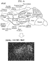
- Examples of the atlas data include two-dimensional image data having names and positional information of individual anatomical regions, such as those shown in Fig. 3 .
- the user may specify atlas data that are publically available or atlas data that the user himself/herself has constructed.
- the interface portion 17 is configured so as to allow the user to input or select a unique ID (IDENTIFICATION, identification information) for each of the anatomical regions in the specimen S, thus specifying a desired anatomical region as the target region.
- a unique ID for example, in the case of the hippocampus, a name such as "Hippocampus” or an abbreviation such as "HC” may be used.
- the interface portion 17 is configured so as to input an image-capturing instruction to the map-image-acquisition portion 19 when the user gives an instruction to capture an image.
- the map-image-acquisition portion 19 is configured so as to dispose the low-magnification objective lens 15, which is set in advance, in the optical path of the laser beam by rotating the revolver with respect to the microscope main body 11.
- the map-image-acquisition portion 19 is configured so as to move, stepwise at a predetermined pitch on the basis of the image-capturing instruction from the interface portion 17, the stage 13 in the Z-direction with respect to the microscope main body 11, thus capturing a Z-stack image (map image) of the specimen S.
- the objective lens 15 to be selected by the map-image-acquisition portion 19 may be set by the user in advance.
- the map-image-acquisition portion 19 is configured so as to acquire, in the case in which the specimen S is too large to fit in a single viewing field, images of a plurality of areas in XY-directions by moving the stage 13 in the X-direction and the Y-direction with respect to the microscope main body 11 at each of the Z-positions, and so as to combine the images for the same Z-position into a single stack image (map image).
- the processing portion 21 is configured so as to calculate, by means of registration processing, conversion parameters for positioning the atlas data specified by the interface portion 17 with respect to the map image of the specimen S acquired by using the microscope apparatus 1.
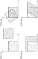
- Examples of the conversion parameters include: rigid-transformation parameters for moving the atlas data as shown in Fig. 4A and for rotating the atlas data as shown in Fig. 4B ; affine-transformation parameters for reducing or enlarging the atlas data as shown in Fig. 4C and for shearing the atlas data as shown in Fig. 4D ; and non-linear transformation parameters for converting the atlas data in a non-linear, complex manner as shown in Fig. 5 .
- the processing portion 21 is configured so as to convert the atlas data by using any one of the above-described types of conversion parameters, so as to compare the converted atlas data with the map image, and so as to calculate the similarity between the converted atlas data and the map image by means of, for example, normalized cross-correlation.
- the processing portion 21 is configured so as to change the type of conversion parameters; so as to, for each type of conversion parameter, convert the atlas data and to calculate the similarities between the converted atlas data and the map image; and so as to calculate, for example, by means of the steepest descent method, the type of conversion parameter with which a maximum similarity is achieved.
- the atlas data be converted to, for example, gray-scale 1-ch data (data in which the target organ, for example, the brain, and organs other than the brain are distinguished from each other) or 1-bit data.
- processing portion 21 is configured so as to calculate the XYZ-coordinates of the target region in the map image by applying the calculated conversion parameters to the target region in the atlas data specified by the user, thus calibrating the atlas data in the coordinate system of the map image, as shown in Fig. 6 .
- the high-resolution image-acquisition portion 23 is configured so as to place the high-magnification objective lens 15, which is set in advance, in the optical path of the laser beam by rotating the revolver with respect to the microscope main body 11.
- the high-resolution image-acquisition portion 23 is configured so as to move, with respect to the microscope main body 11, the stage 13 to the XY-coordinates of the target region, calculated by the processing portion 21.
- the objective lens 15 to be selected by the high-resolution image-acquisition portion 23 may be set by the user in advance.
- the high-resolution image-acquisition portion 23 is configured so as to allow the microscope apparatus 1 to acquire a Z-stack image (high-resolution image) of the target region by moving, stepwise at a predetermined pitch, the stage 13 in the Z-direction with respect to the microscope main body 11 at the XY-coordinates of the target region.
- the high-resolution image-acquisition portion 23 is configured so as to allow the microscope apparatus 1 to acquire, in the case in which the target region is too large to fit in a single viewing field, images of a plurality of areas in XY-directions by moving the stage 13 in the X-direction and the Y-direction with respect to the microscope main body 11 at each of the Z-positions.
- the user specifies desired atlas data to be used by means of the interface portion 17, and also inputs the ID of a desired target region in the specimen S.
- the user gives an image-capturing instruction by means of the interface portion 17.
- the map-image-acquisition portion 19 actuates the revolver in response to the image-capturing instruction from the interface portion 17, and thus, the low-magnification objective lens 15, which is set in advance, is placed in the optical path of the laser beam.
- the stage 13 is moved stepwise in the Z-direction, the stage 13 is moved in the XY-directions at each of the Z-positions, and thus, images of a plurality of areas of the specimen S are acquired in the XY-directions.
- the map-image-acquisition portion 19 the images of the individual areas are combined for the same Z-position, thus generating a single stack image (map image) of the entire specimen S.
- the registration processing is applied to the atlas data specified by the user, and the conversion parameters for positioning the atlas data in the map image are calculated.
- the calculated conversion parameters are applied to the atlas data, the atlas data are positioned in the map image, as shown in Fig. 6 , and the XYZ-coordinates of the target region in the map image are calculated.
- the revolver is actuated and the high-magnification objective lens 15, which is set in advance, is placed in the optical path of the laser beam.
- the stage 13 is moved to the calculated XY-coordinates of the target region, the stage 13 is moved stepwise in the Z-direction at those XY-coordinates, and the Z-stack image (high-resolution image) of the target region is acquired.
- the image-acquisition system 10 by acquiring the map image of the entire specimen S at a low magnification and by acquiring the image of the desired target region at a high magnification, it is possible to decrease the amount of time required to acquire an image and to decrease the volume of the image data as compared with the case in which an image of the entire specimen S is acquired at a high resolution.
- This embodiment can be modified as described below.
- the interface portion 17 may display, on the monitor 5, atlas data in which the ID of the target region and boundaries among the individual anatomical regions of the specimen S are indicated.
- the interface portion 17 may be configured so that, when the user clicks a desired anatomical region in the atlas data on the monitor 5 by using the mouse 9, the clicked anatomical region is assumed to have been specified as the target region.
- the user can specify the target region in an intuitive, simple manner by viewing the atlas data displayed on the monitor 5.
- the high-resolution image-acquisition portion 23 may control the microscope apparatus 1 so as to acquire a plurality of Z-stack images by shifting positions thereof stepwise in the specimen S in the Z-direction at a finer Z-step (pitch) than that used by the map-image-acquisition portion 19.
- the Z-step size may be set to be half of an optical resolving power that is calculated on the basis of the observation conditions used during high-resolution image acquisition.
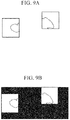
- the map-image-acquisition portion 19 may perform the registration processing by acquiring images of areas in certain portions of the specimen S. For example, as shown in Fig. 8 , it is preferable that, by means of the map-image-acquisition portion 19, images be acquired for two or more locations having distinctive features in outline or the like in the specimen S, and that positions thereof be aligned with respect to the atlas data.
- the stage 13 is moved to one of the areas having the outlines in the specimen S, the user gives the image-capturing instruction by means of the interface portion 17, and an image of that area in the specimen is acquired. This operation is performed at two or more locations having distinctive features in the specimen S.
- marking is applied to a non-acquired portion of the specimen S with respect to the luminance thereof (for example, the luminance thereof is set to be -1), and a map image of the specimen S is generated by combining the marked image with the acquired images of the feature portions.
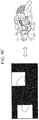
- the atlas data are positioned in the map image by applying the registration processing to the atlas data specified by the user, and the XYZ-coordinates of the desired target region in the map image are calculated.
- the registration processing when calculating the similarity between the atlas data and the map image, it is permissible to use only the acquired images of feature portions and to ignore the non-acquired portions in the map image.
- a camera and a laser-scanning microscope apparatus may be employed as the microscope apparatus 1, a map image including a plurality of anatomical regions in the specimen S may be acquired by using the camera, and a high-resolution image of a target region in the specimen S may be acquired by using the laser-scanning microscope apparatus.
- study regions in a specimen are regions that can be identified by means of unique identification information, and it is possible to apply the present invention to, for example, aside from the anatomical regions, regions defined from the viewpoint of genetics, cell biology, or the like, and regions defined by combining these.
Landscapes
- Physics & Mathematics (AREA)
- Engineering & Computer Science (AREA)
- General Physics & Mathematics (AREA)
- Chemical & Material Sciences (AREA)
- Analytical Chemistry (AREA)
- Optics & Photonics (AREA)
- Multimedia (AREA)
- Computer Vision & Pattern Recognition (AREA)
- Theoretical Computer Science (AREA)
- Microscoopes, Condenser (AREA)
- Studio Devices (AREA)
Abstract
Description
- The present invention relates to an image-acquisition system.
- In the related art, there is a known image-acquisition system with which a target region is set on a low-resolution overall specimen image, for example, a map image, and then, a high-resolution image of the target region is acquired (for example, see Patent Literature 1).
- In the case in which a portion of a region of a specimen needs to be observed in a greater detail, there is a problem in that acquiring a high-resolution overall specimen image increases the amount of time required to acquire the image, and the volume of image data is also increased. With the image-acquisition system described in Patent Literature 1, the overall specimen image is acquired at a low resolution, and the image of the target region is acquired at a high resolution, thus decreasing the amount of time required to acquire an image and decreasing the volume of the image data.
- {Patent Literature 1} Japanese Translation of PCT International Application, Publication No.
2001-519944 - However, there is a problem in that, unless a user has well-developed anatomical knowledge and experience, it is difficult for the user to, for example, in a low-resolution map image in which the brain or the like is captured, accurately find a region of a portion, such as the hippocampus, and to set this regions as the target region.
- The present invention has been conceived in light of the above-described circumstances, and an object thereof is to provide an image-acquisition system with which it is possible to acquire, in an efficient, simple manner, a high-resolution image of a target region in a specimen.
- In order to achieve the above-described object, the present invention provides the following solutions.
- An aspect of the present invention is an image-acquisition system including: an image-acquisition portion that acquires an image of a specimen; a first image-acquisition control portion that controls the image-acquisition portion so as to acquire, at a first image-capturing magnification, a first image that includes a plurality of study regions in the specimen; a target-region specifying portion that allows a user to specify a desired study region as a target region by means of unique identification information assigned to the individual study regions; a position-calculating portion that calculates a spatial position of the target region specified by the target-region specifying portion on the basis of the first image acquired by the image-acquisition portion and a reference image having positional information of the individual study regions; and a second image-acquisition control portion that controls, on the basis of the spatial position of the target region calculated by the position-calculating portion, the image-acquisition portion so as to acquire a second image of the target region in the specimen at a second image-capturing magnification which is a magnification that is greater than the first image-capturing magnification.
- With this aspect, when a first image that includes a plurality of study regions in the specimen is acquired after the first image-acquisition control portion controls the image-acquisition portion, the user specifies a desired study region in the specimen as a target region by using the target-region specifying portion, and then, the position-calculating portion calculates, on the basis of the first image and the reference image having the positional information of the study regions, the spatial position of the target region specified by the user. Then, on the basis of that spatial position of the target region, the second image-acquisition control portion controls the image-acquisition portion, and thus, a second image of the target region in the specimen is acquired.
- Here, by acquiring the first image at a low magnification and by acquiring the second image at a high magnification, it is possible to decrease the amount of time required to acquire an image and to decrease the volume of the image data as compared with the case in which an image of the entire specimen is acquired at a high resolution. In this case, even without well-developed anatomical knowledge and experience, just by having the user input the identification information of the desired study region, it is possible to acquire a high-resolution image of that target region. Therefore, it is possible to acquire a high-resolution image of a target region in the specimen in an efficient, simple manner.
- In the above-described aspect, the position-calculating portion may perform registration processing for calculating conversion parameters for positioning the reference image with respect to the first image and calculates the spatial position of the target region on the basis of the calculated conversion parameters.
- By employing such a configuration, even in the case in which the position, the direction, the shape, or the like of the target region in the reference image do not align with the position, the direction, the shape, or the like of a corresponding study region in the first image, the reference image and the first image are associated with each other by means of the registration processing, and thus, it is possible to calculate the spatial position of the target region in a simple, precise manner.
- In the above-described aspect, the target-region specifying portion may display the reference image in which identification information of the target region and boundaries of the individual study regions are indicated.
- By employing such a configuration, the user can intuitively specify the target region by viewing the displayed reference image.
- In the above-described aspect, the first image-acquisition control portion may control the image-acquisition portion so as to acquire a plurality of the first images, the positions of which are shifted stepwise in an optical-axis direction in the specimen, and the second image-acquisition control portion may control the image-acquisition portion so as to acquire a plurality of the second images, the positions of which are shifted stepwise in the optical-axis direction in the specimen at a finer pitch than that used by the first image-acquisition control portion.
- By employing such a configuration, it is possible to observe the target region in the specimen by using a three-dimensional image in which the resolving power is also enhanced in the optical-axis direction in the specimen.
- In the above-described aspect, the first image-acquisition control portion may control the image-acquisition portion so as to acquire an image of the entire specimen as the first image.
- By employing such a configuration, it is possible to specify a target region from all study regions in the specimen by using a single first image.
- The present invention affords an advantage in that it is possible to acquire, in an efficient, simple manner, a high-resolution image of a target region in a specimen.
-
- {
Fig. 1} Fig. 1 is a configuration diagram showing, in outline, an image-acquisition system according to an embodiment of the present invention. - {
Fig. 2} Fig. 2 is a diagram showing examples of input fields and an instruction button displayed on a monitor inFig. 1 by an interface portion. - {
Fig. 3} Fig. 3 is a diagram showing an example of brain atlas data. - {
Fig. 4A} Fig. 4A is a diagram for explaining movement of atlas data. - {
Fig. 4B} Fig. 4B is a diagram for explaining rotation of the atlas data. - {
Fig. 4C} Fig. 4C is a diagram for explaining reduction and enlargement of the atlas data. - {
Fig. 4D} Fig. 4D is a diagram for explaining shearing of the atlas data. - {
Fig. 5} Fig. 5 is a diagram for explaining non-linear complex conversion of the atlas data. - {
Fig. 6} Fig. 6 is a diagram for explaining positioning between the atlas data to which conversion parameters have been applied and a map image. - {
Fig. 7} Fig. 7 is a diagram showing examples of atlas data, input fields, and an instruction button displayed on a monitor by an image-acquisition system according to a first modification of the embodiment of the present invention. - {
Fig. 8} Fig. 8 is a diagram showing examples of two feature portions in a specimen processed by an image-acquisition system according to a third modification of the embodiment of the present invention. - {
Fig. 9A} Fig. 9A is a diagram for explaining an image showing areas of certain portions of the specimen. - {
Fig. 9B} Fig. 9B is a diagram for explaining a map image of the specimen in which the luminance of a non-acquired portion is set to -1. - {
Fig. 9C} Fig. 9C is a diagram for explaining positioning between the atlas data to which conversion parameters have been applied and the certain portions in the map image. - An image-acquisition system according to an embodiment of the present invention will be described below with reference to the drawings.
- As shown in
Fig. 1 , an image-acquisition system 10 according to this embodiment is provided with: a microscope apparatus (image-acquisition portion) 1 that acquires an image of a specimen S; a PC (Personal Computer) 3 that controls the microscope apparatus 1; and amonitor 5, akeyboard 7, and amouse 9 that are connected to the PC 3. - The microscope apparatus 1 is provided with: a microscope
main body 11 equipped with a light source, a photodetector, a revolver, and so forth, which are not illustrated; astage 13 on which the specimen S is placed; and a plurality ofobjective lenses 15 that have magnifications that are different from each other. In this embodiment, the brain, which has a plurality of anatomical regions (study regions), such as the visual cortical area, the hippocampus, and so forth will be described as an example of the specimen S. - The
stage 13 is configured so as to be movable in the optical-axis direction (Z-direction) of theobjective lens 15 and in directions (X-direction and Y-direction) that intersect the optical-axis direction of theobjective lens 15. - The plurality of
objective lenses 15 are mounted on the revolver and are switched among by means of the revolver, and thus, one of them is selectively placed in the optical path of a laser beam. - This microscope apparatus 1 is configured so as to radiate a laser beam emitted from the light source onto the specimen S via the
objective lens 15, and so that, by collecting return light coming from the specimen S via theobjective lens 15 and by detecting the return light by using the photodetector, it is possible to acquire an image in accordance with the luminance of the return light. - The PC 3 is provided with: an interface portion (target-region specifying portion) 17 that allows a user to specify a desired anatomical region in the specimen S as a target region; a map-image-acquisition portion (first image-acquisition control portion) 19 that controls the microscope apparatus 1 so as to acquire, at a low magnification (first image-capturing magnification), a map image (first image) that includes a plurality of anatomical regions in the specimen S; a processing portion (position-calculating portion) 21 that calculates the spatial position of the target region specified by the
interface portion 17; and a high-resolution image-acquisition portion (second image-acquisition control portion) 23 that controls the microscope apparatus 1 so as to acquire, at a magnification (second image-capturing magnification) that is greater than that of the map image, a high-resolution image (second image) of the target region in the specimen S. - The
interface portion 17, the map-image-acquisition portion 19, theprocessing portion 21, and the high-resolution image-acquisition portion 23 are individually realized by means of software. - As shown in
Fig. 2 , theinterface portion 17 is configured so as to receive instructions from the user, which are input via input fields "Atlas data" and "Target region" and an image-capture starting button "Acquire" displayed on themonitor 5 by using themouse 9 and thekeyboard 7. - This
interface portion 17 is configured so as to allow the user to specify, for example, atlas data (reference image) that has positional information of the individual anatomical regions in the specimen S. Examples of the atlas data include two-dimensional image data having names and positional information of individual anatomical regions, such as those shown inFig. 3 . The user may specify atlas data that are publically available or atlas data that the user himself/herself has constructed. - In addition, the
interface portion 17 is configured so as to allow the user to input or select a unique ID (IDENTIFICATION, identification information) for each of the anatomical regions in the specimen S, thus specifying a desired anatomical region as the target region. Regarding the ID, for example, in the case of the hippocampus, a name such as "Hippocampus" or an abbreviation such as "HC" may be used. In addition, theinterface portion 17 is configured so as to input an image-capturing instruction to the map-image-acquisition portion 19 when the user gives an instruction to capture an image. - The map-image-
acquisition portion 19 is configured so as to dispose the low-magnification objective lens 15, which is set in advance, in the optical path of the laser beam by rotating the revolver with respect to the microscopemain body 11. In addition, the map-image-acquisition portion 19 is configured so as to move, stepwise at a predetermined pitch on the basis of the image-capturing instruction from theinterface portion 17, thestage 13 in the Z-direction with respect to the microscopemain body 11, thus capturing a Z-stack image (map image) of the specimen S. Theobjective lens 15 to be selected by the map-image-acquisition portion 19 may be set by the user in advance. - In addition, the map-image-
acquisition portion 19 is configured so as to acquire, in the case in which the specimen S is too large to fit in a single viewing field, images of a plurality of areas in XY-directions by moving thestage 13 in the X-direction and the Y-direction with respect to the microscopemain body 11 at each of the Z-positions, and so as to combine the images for the same Z-position into a single stack image (map image). - The
processing portion 21 is configured so as to calculate, by means of registration processing, conversion parameters for positioning the atlas data specified by theinterface portion 17 with respect to the map image of the specimen S acquired by using the microscope apparatus 1. - Examples of the conversion parameters include: rigid-transformation parameters for moving the atlas data as shown in
Fig. 4A and for rotating the atlas data as shown inFig. 4B ; affine-transformation parameters for reducing or enlarging the atlas data as shown inFig. 4C and for shearing the atlas data as shown inFig. 4D ; and non-linear transformation parameters for converting the atlas data in a non-linear, complex manner as shown inFig. 5 . - Specifically, the
processing portion 21 is configured so as to convert the atlas data by using any one of the above-described types of conversion parameters, so as to compare the converted atlas data with the map image, and so as to calculate the similarity between the converted atlas data and the map image by means of, for example, normalized cross-correlation. - Also, the
processing portion 21 is configured so as to change the type of conversion parameters; so as to, for each type of conversion parameter, convert the atlas data and to calculate the similarities between the converted atlas data and the map image; and so as to calculate, for example, by means of the steepest descent method, the type of conversion parameter with which a maximum similarity is achieved. Note that, when performing the registration processing, it is preferable that the atlas data be converted to, for example, gray-scale 1-ch data (data in which the target organ, for example, the brain, and organs other than the brain are distinguished from each other) or 1-bit data. - In addition, the
processing portion 21 is configured so as to calculate the XYZ-coordinates of the target region in the map image by applying the calculated conversion parameters to the target region in the atlas data specified by the user, thus calibrating the atlas data in the coordinate system of the map image, as shown inFig. 6 . - The high-resolution image-
acquisition portion 23 is configured so as to place the high-magnification objective lens 15, which is set in advance, in the optical path of the laser beam by rotating the revolver with respect to the microscopemain body 11. In addition, the high-resolution image-acquisition portion 23 is configured so as to move, with respect to the microscopemain body 11, thestage 13 to the XY-coordinates of the target region, calculated by theprocessing portion 21. Theobjective lens 15 to be selected by the high-resolution image-acquisition portion 23 may be set by the user in advance. - In addition, the high-resolution image-
acquisition portion 23 is configured so as to allow the microscope apparatus 1 to acquire a Z-stack image (high-resolution image) of the target region by moving, stepwise at a predetermined pitch, thestage 13 in the Z-direction with respect to the microscopemain body 11 at the XY-coordinates of the target region. The high-resolution image-acquisition portion 23 is configured so as to allow the microscope apparatus 1 to acquire, in the case in which the target region is too large to fit in a single viewing field, images of a plurality of areas in XY-directions by moving thestage 13 in the X-direction and the Y-direction with respect to the microscopemain body 11 at each of the Z-positions. - The operation of the thus-configured image-
acquisition system 10 will be described below. - In order to observe the brain, serving as the specimen S, on the
stage 13 by using the image-acquisition system 10 according to this embodiment, the user specifies desired atlas data to be used by means of theinterface portion 17, and also inputs the ID of a desired target region in the specimen S. Next, the user gives an image-capturing instruction by means of theinterface portion 17. - Next, the map-image-
acquisition portion 19 actuates the revolver in response to the image-capturing instruction from theinterface portion 17, and thus, the low-magnification objective lens 15, which is set in advance, is placed in the optical path of the laser beam. Then, by means of the map-image-acquisition portion 19, thestage 13 is moved stepwise in the Z-direction, thestage 13 is moved in the XY-directions at each of the Z-positions, and thus, images of a plurality of areas of the specimen S are acquired in the XY-directions. Then, by means of the map-image-acquisition portion 19, the images of the individual areas are combined for the same Z-position, thus generating a single stack image (map image) of the entire specimen S. - Next, by means of the
processing portion 21, the registration processing is applied to the atlas data specified by the user, and the conversion parameters for positioning the atlas data in the map image are calculated. Then, by means of theprocessing portion 21, the calculated conversion parameters are applied to the atlas data, the atlas data are positioned in the map image, as shown inFig. 6 , and the XYZ-coordinates of the target region in the map image are calculated. - Next, by means of the high-resolution image-
acquisition portion 23, the revolver is actuated and the high-magnification objective lens 15, which is set in advance, is placed in the optical path of the laser beam. Next, by means of the high-resolution image-acquisition portion 23, thestage 13 is moved to the calculated XY-coordinates of the target region, thestage 13 is moved stepwise in the Z-direction at those XY-coordinates, and the Z-stack image (high-resolution image) of the target region is acquired. - As has been described above, with the image-
acquisition system 10 according to this embodiment, by acquiring the map image of the entire specimen S at a low magnification and by acquiring the image of the desired target region at a high magnification, it is possible to decrease the amount of time required to acquire an image and to decrease the volume of the image data as compared with the case in which an image of the entire specimen S is acquired at a high resolution. - In this case, even without well-developed anatomical knowledge and experience, just by having the user input the ID of the desired anatomical region in the specimen S, a high-resolution image of that target region is acquired. Therefore, it is possible to acquire a high-resolution image of a target region in the specimen S in an efficient, simple manner.
- In addition, even in the case in which the position, the direction, the shape, or the like of a target region in the atlas data do not align with the position, the direction, the shape, or the like of a corresponding anatomical region in the map image of the entire specimen S, because the atlas data and the map image are associated with each other by means of the registration processing, it is possible to calculate the spatial position of the target region in a simple, precise manner.
- This embodiment can be modified as described below.
- As a first modification, as shown in
Fig. 7 , theinterface portion 17 may display, on themonitor 5, atlas data in which the ID of the target region and boundaries among the individual anatomical regions of the specimen S are indicated. - In this case, the
interface portion 17 may be configured so that, when the user clicks a desired anatomical region in the atlas data on themonitor 5 by using themouse 9, the clicked anatomical region is assumed to have been specified as the target region. - By doing so, the user can specify the target region in an intuitive, simple manner by viewing the atlas data displayed on the
monitor 5. - As a second modification, the high-resolution image-
acquisition portion 23 may control the microscope apparatus 1 so as to acquire a plurality of Z-stack images by shifting positions thereof stepwise in the specimen S in the Z-direction at a finer Z-step (pitch) than that used by the map-image-acquisition portion 19. - In this case, for example, the Z-step size may be set to be half of an optical resolving power that is calculated on the basis of the observation conditions used during high-resolution image acquisition.
- By doing so, it is possible to observe the target region in the specimen S in detail by using a three-dimensional high-resolution image in which the resolving power is also enhanced in the Z-direction of the specimen S.
- As a third modification, the map-image-
acquisition portion 19 may perform the registration processing by acquiring images of areas in certain portions of the specimen S. For example, as shown inFig. 8 , it is preferable that, by means of the map-image-acquisition portion 19, images be acquired for two or more locations having distinctive features in outline or the like in the specimen S, and that positions thereof be aligned with respect to the atlas data. - In this case, as shown in
Fig. 9A , by means of the map-image-acquisition portion 19, thestage 13 is moved to one of the areas having the outlines in the specimen S, the user gives the image-capturing instruction by means of theinterface portion 17, and an image of that area in the specimen is acquired. This operation is performed at two or more locations having distinctive features in the specimen S. Next, by means of the map-image-acquisition portion 19, as shown inFig. 9B , marking is applied to a non-acquired portion of the specimen S with respect to the luminance thereof (for example, the luminance thereof is set to be -1), and a map image of the specimen S is generated by combining the marked image with the acquired images of the feature portions. - Next, by means of the
processing portion 21, as shown inFig. 9C , the atlas data are positioned in the map image by applying the registration processing to the atlas data specified by the user, and the XYZ-coordinates of the desired target region in the map image are calculated. In the registration processing, when calculating the similarity between the atlas data and the map image, it is permissible to use only the acquired images of feature portions and to ignore the non-acquired portions in the map image. With regard to the acquisition of a high-resolution image of the target region for which the XYZ-coordinates have been calculated, descriptions thereof will be omitted because the procedures are the same as those of the above-described embodiment. - With this modification, it is possible to decrease the amount of time required to acquire an image and to decrease the volume of the image data by amounts afforded by eliminating the need to generate a map image of the entire specimen S, and thus, it is possible to enhance the work efficiency.
- As has been described above, although the embodiment of the present invention has been described in detail with reference to the drawings, specific configurations thereof are not limited to this embodiment, and design alterations or the like within a range that does not depart from the scope of the present invention are also encompassed. For example, the present invention is not limited to the forms applied to the above-described embodiment and modifications; the present invention may be applied to embodiments in which these embodiment and modifications are appropriately combined, without particular limitation. In addition, in the above-described embodiment, a camera and a laser-scanning microscope apparatus may be employed as the microscope apparatus 1, a map image including a plurality of anatomical regions in the specimen S may be acquired by using the camera, and a high-resolution image of a target region in the specimen S may be acquired by using the laser-scanning microscope apparatus.
- In addition, in the above-described embodiment, although anatomical regions have been described as examples of study regions in a specimen, it suffices that study regions in a specimen be regions that can be identified by means of unique identification information, and it is possible to apply the present invention to, for example, aside from the anatomical regions, regions defined from the viewpoint of genetics, cell biology, or the like, and regions defined by combining these.
-
- 1 microscope apparatus (image-acquisition portion)
- 10 image-acquisition system
- 17 interface portion (target-region specifying portion)
- 19 map-image-acquisition portion (first image-acquisition control portion)
- 21 processing portion (position-calculating portion)
- 23 high-resolution image-acquisition portion (second image-acquisition control portion)
- S specimen
Claims (5)
- An image-acquisition system comprising:an image-acquisition portion that acquires an image of a specimen;a first image-acquisition control portion that controls the image-acquisition portion so as to acquire, at a first image-capturing magnification, a first image that includes a plurality of study regions in the specimen;a target-region specifying portion that allows a user to specify a desired study region as a target region by means of unique identification information assigned to the individual study regions;a position-calculating portion that calculates a spatial position of the target region specified by the target-region specifying portion on the basis of the first image acquired by the image-acquisition portion and a reference image having positional information of the individual study regions; anda second image-acquisition control portion that controls, on the basis of the spatial position of the target region calculated by the position-calculating portion, the image-acquisition portion so as to acquire a second image of the target region in the specimen at a second image-capturing magnification which is a magnification that is greater than the first image-capturing magnification.
- An image-acquisition system according to Claim 1, wherein the position-calculating portion performs registration processing for calculating conversion parameters for positioning the reference image with respect to the first image and calculates the spatial position of the target region on the basis of the calculated conversion parameters.
- An image-acquisition system according to Claim 1 or 2, wherein the target-region specifying portion displays the reference image in which identification information of the target region and boundaries of the individual study regions are indicated.
- An image-acquisition system according to any one of Claims 1 to 3,
wherein the first image-acquisition control portion controls the image-acquisition portion so as to acquire a plurality of the first images, the positions of which are shifted stepwise in an optical-axis direction in the specimen, and
wherein the second image-acquisition control portion controls the image-acquisition portion so as to acquire a plurality of the second images, the positions of which are shifted stepwise in the optical-axis direction in the specimen at a finer pitch than that used by the first image-acquisition control portion. - An image-acquisition system according to any one of Claims 1 to 4, wherein the first image-acquisition control portion controls the image-acquisition portion so as to acquire an image of the entire specimen as the first image.
Applications Claiming Priority (1)
| Application Number | Priority Date | Filing Date | Title |
|---|---|---|---|
| JP2016061121A JP2017173653A (en) | 2016-03-25 | 2016-03-25 | Image acquisition system |
Publications (1)
| Publication Number | Publication Date |
|---|---|
| EP3223055A1 true EP3223055A1 (en) | 2017-09-27 |
Family
ID=58231359
Family Applications (1)
| Application Number | Title | Priority Date | Filing Date |
|---|---|---|---|
| EP17157350.4A Withdrawn EP3223055A1 (en) | 2016-03-25 | 2017-02-22 | Image-acquisition system |
Country Status (3)
| Country | Link |
|---|---|
| US (1) | US10429631B2 (en) |
| EP (1) | EP3223055A1 (en) |
| JP (1) | JP2017173653A (en) |
Families Citing this family (4)
| Publication number | Priority date | Publication date | Assignee | Title |
|---|---|---|---|---|
| JP7506523B2 (en) | 2020-05-20 | 2024-06-26 | 株式会社エビデント | Microscope system, control method, and program |
| JP7506524B2 (en) | 2020-05-20 | 2024-06-26 | 株式会社エビデント | Microscope system, control method, and program |
| JP7784429B2 (en) * | 2021-06-29 | 2025-12-11 | 浜松ホトニクス株式会社 | Optical image processing method, machine learning method, trained model, machine learning preprocessing method, optical image processing module, optical image processing program, and optical image processing system |
| CN118762287B (en) * | 2024-09-06 | 2024-11-29 | 陕西天慧空间规划设计院有限公司 | High-resolution remote sensing image detail change identification method and system |
Citations (5)
| Publication number | Priority date | Publication date | Assignee | Title |
|---|---|---|---|---|
| JP2001519944A (en) | 1997-03-03 | 2001-10-23 | バクス リサーチ ラボラトリーズ インコーポレイテッド | Method and apparatus for acquiring and reconstructing a magnified image of a sample from a computer controlled microscope |
| US20030228042A1 (en) * | 2002-06-06 | 2003-12-11 | Usha Sinha | Method and system for preparation of customized imaging atlas and registration with patient images |
| US20100119119A1 (en) * | 2008-11-07 | 2010-05-13 | General Electric Company | Automated systems and methods for screening zebrafish |
| US20140029812A1 (en) * | 2012-07-30 | 2014-01-30 | General Electric Company | Methods and systems for determining a transformation function to automatically register different modality medical images |
| WO2014165989A1 (en) * | 2013-04-08 | 2014-10-16 | Wdi Wise Device Inc. | Method and apparatus for small and large format histology sample examination |
Family Cites Families (2)
| Publication number | Priority date | Publication date | Assignee | Title |
|---|---|---|---|---|
| WO2005119575A2 (en) * | 2004-05-27 | 2005-12-15 | Aperio Technologies, Inc | Systems and methods for creating and viewing three dimensional virtual slides |
| US10139613B2 (en) * | 2010-08-20 | 2018-11-27 | Sakura Finetek U.S.A., Inc. | Digital microscope and method of sensing an image of a tissue sample |
-
2016
- 2016-03-25 JP JP2016061121A patent/JP2017173653A/en active Pending
-
2017
- 2017-02-13 US US15/431,268 patent/US10429631B2/en active Active
- 2017-02-22 EP EP17157350.4A patent/EP3223055A1/en not_active Withdrawn
Patent Citations (5)
| Publication number | Priority date | Publication date | Assignee | Title |
|---|---|---|---|---|
| JP2001519944A (en) | 1997-03-03 | 2001-10-23 | バクス リサーチ ラボラトリーズ インコーポレイテッド | Method and apparatus for acquiring and reconstructing a magnified image of a sample from a computer controlled microscope |
| US20030228042A1 (en) * | 2002-06-06 | 2003-12-11 | Usha Sinha | Method and system for preparation of customized imaging atlas and registration with patient images |
| US20100119119A1 (en) * | 2008-11-07 | 2010-05-13 | General Electric Company | Automated systems and methods for screening zebrafish |
| US20140029812A1 (en) * | 2012-07-30 | 2014-01-30 | General Electric Company | Methods and systems for determining a transformation function to automatically register different modality medical images |
| WO2014165989A1 (en) * | 2013-04-08 | 2014-10-16 | Wdi Wise Device Inc. | Method and apparatus for small and large format histology sample examination |
Non-Patent Citations (4)
| Title |
|---|
| ANONYMOUS: "TestData.wiki . Vaa3D/Vaa3D_Wiki Wiki . GitHub", 2 February 2016 (2016-02-02), XP055492731, Retrieved from the Internet <URL:https://github.com/Vaa3D/Vaa3D_Wiki/wiki/TestData.wiki/af2c25fb6af8ceacf2f643f276695b13503cb36f> [retrieved on 20180716] * |
| FUHUI LONG ET AL: "Visualization and Analysis of 3D Microscopic Images", PLOS COMPUTATIONAL BIOLOGY, vol. 8, no. 6, 14 June 2012 (2012-06-14), US, pages e1002519, XP055492656, ISSN: 1553-734X, DOI: 10.1371/journal.pcbi.1002519 * |
| KAITLIN CORBIN: "Setting up Micro-Magellan for Device control", 23 October 2015 (2015-10-23), XP055390701, Retrieved from the Internet <URL:http://biomicroscopy.ucsf.edu/mediawiki/images/6/62/Micro-MagellanUserGuide.pdf> [retrieved on 20170713] * |
| MIKULA ET AL: "Internet-enabled high-resolution brain mapping and virtual microscopy", NEUROI, ELSEVIER, AMSTERDAM, NL, vol. 35, no. 1, 14 February 2007 (2007-02-14), pages 9 - 15, XP005907161, ISSN: 1053-8119, DOI: 10.1016/J.NEUROIMAGE.2006.11.053 * |
Also Published As
| Publication number | Publication date |
|---|---|
| US10429631B2 (en) | 2019-10-01 |
| JP2017173653A (en) | 2017-09-28 |
| US20170276925A1 (en) | 2017-09-28 |
Similar Documents
| Publication | Publication Date | Title |
|---|---|---|
| JP6310671B2 (en) | Laser microdissection region definition method and related laser microdissection system | |
| US10429631B2 (en) | Image-aquisition system | |
| US20150168706A1 (en) | Microscope and Method for SPIM Microscopy | |
| US10051241B2 (en) | Method and apparatus for image combination and displaying the combined image | |
| US11010914B2 (en) | Image processing device, microscope system, image processing method, and program | |
| US11222400B2 (en) | Image processing device, microscope system, image processing method, and computer program for displaying magnified images from different observation directions | |
| US20250072977A1 (en) | Automated registration of preoperative volume image data, using a search image | |
| US10721413B2 (en) | Microscopy system, microscopy method, and computer readable recording medium | |
| EP3023825A1 (en) | Microscope system | |
| US10234668B2 (en) | Microscope system | |
| US10475198B2 (en) | Microscope system and specimen observation method | |
| EP2804037A1 (en) | Microscope system | |
| US11914134B2 (en) | Microscope system for imaging a sample region and corresponding method | |
| JP6721046B2 (en) | Image processing apparatus, image processing method and program | |
| JP2023000013A (en) | Three-dimensional detection microscope system | |
| CN111433594B (en) | filming device | |
| JP6796524B2 (en) | Image processing equipment, observation equipment, and image processing methods | |
| JP2009176572A (en) | Control device and control method for electron microscope | |
| US10404965B2 (en) | Microscope system | |
| CN121053409A (en) | Methods and systems for searching and locating chromosome karyotypes |
Legal Events
| Date | Code | Title | Description |
|---|---|---|---|
| PUAI | Public reference made under article 153(3) epc to a published international application that has entered the european phase |
Free format text: ORIGINAL CODE: 0009012 |
|
| STAA | Information on the status of an ep patent application or granted ep patent |
Free format text: STATUS: THE APPLICATION HAS BEEN PUBLISHED |
|
| AK | Designated contracting states |
Kind code of ref document: A1 Designated state(s): AL AT BE BG CH CY CZ DE DK EE ES FI FR GB GR HR HU IE IS IT LI LT LU LV MC MK MT NL NO PL PT RO RS SE SI SK SM TR |
|
| AX | Request for extension of the european patent |
Extension state: BA ME |
|
| STAA | Information on the status of an ep patent application or granted ep patent |
Free format text: STATUS: REQUEST FOR EXAMINATION WAS MADE |
|
| 17P | Request for examination filed |
Effective date: 20180302 |
|
| RBV | Designated contracting states (corrected) |
Designated state(s): AL AT BE BG CH CY CZ DE DK EE ES FI FR GB GR HR HU IE IS IT LI LT LU LV MC MK MT NL NO PL PT RO RS SE SI SK SM TR |
|
| STAA | Information on the status of an ep patent application or granted ep patent |
Free format text: STATUS: EXAMINATION IS IN PROGRESS |
|
| 17Q | First examination report despatched |
Effective date: 20180724 |
|
| STAA | Information on the status of an ep patent application or granted ep patent |
Free format text: STATUS: THE APPLICATION IS DEEMED TO BE WITHDRAWN |
|
| 18D | Application deemed to be withdrawn |
Effective date: 20191001 |