EP3223050B1 - Kit of parts - Google Patents
Kit of parts Download PDFInfo
- Publication number
- EP3223050B1 EP3223050B1 EP15860861.2A EP15860861A EP3223050B1 EP 3223050 B1 EP3223050 B1 EP 3223050B1 EP 15860861 A EP15860861 A EP 15860861A EP 3223050 B1 EP3223050 B1 EP 3223050B1
- Authority
- EP
- European Patent Office
- Prior art keywords
- locking
- ring
- section
- adapter
- connecting surface
- Prior art date
- Legal status (The legal status is an assumption and is not a legal conclusion. Google has not performed a legal analysis and makes no representation as to the accuracy of the status listed.)
- Active
Links
Images







Classifications
-
- G—PHYSICS
- G02—OPTICS
- G02B—OPTICAL ELEMENTS, SYSTEMS OR APPARATUS
- G02B6/00—Light guides; Structural details of arrangements comprising light guides and other optical elements, e.g. couplings
- G02B6/24—Coupling light guides
- G02B6/36—Mechanical coupling means
- G02B6/38—Mechanical coupling means having fibre to fibre mating means
- G02B6/3807—Dismountable connectors, i.e. comprising plugs
- G02B6/381—Dismountable connectors, i.e. comprising plugs of the ferrule type, e.g. fibre ends embedded in ferrules, connecting a pair of fibres
- G02B6/3825—Dismountable connectors, i.e. comprising plugs of the ferrule type, e.g. fibre ends embedded in ferrules, connecting a pair of fibres with an intermediate part, e.g. adapter, receptacle, linking two plugs
-
- G—PHYSICS
- G02—OPTICS
- G02B—OPTICAL ELEMENTS, SYSTEMS OR APPARATUS
- G02B6/00—Light guides; Structural details of arrangements comprising light guides and other optical elements, e.g. couplings
- G02B6/24—Coupling light guides
- G02B6/36—Mechanical coupling means
- G02B6/38—Mechanical coupling means having fibre to fibre mating means
-
- G—PHYSICS
- G02—OPTICS
- G02B—OPTICAL ELEMENTS, SYSTEMS OR APPARATUS
- G02B6/00—Light guides; Structural details of arrangements comprising light guides and other optical elements, e.g. couplings
- G02B6/24—Coupling light guides
- G02B6/36—Mechanical coupling means
- G02B6/38—Mechanical coupling means having fibre to fibre mating means
- G02B6/3807—Dismountable connectors, i.e. comprising plugs
- G02B6/389—Dismountable connectors, i.e. comprising plugs characterised by the method of fastening connecting plugs and sockets, e.g. screw- or nut-lock, snap-in, bayonet type
- G02B6/3891—Bayonet type
-
- G—PHYSICS
- G02—OPTICS
- G02B—OPTICAL ELEMENTS, SYSTEMS OR APPARATUS
- G02B6/00—Light guides; Structural details of arrangements comprising light guides and other optical elements, e.g. couplings
- G02B6/24—Coupling light guides
- G02B6/36—Mechanical coupling means
- G02B6/38—Mechanical coupling means having fibre to fibre mating means
- G02B6/3807—Dismountable connectors, i.e. comprising plugs
- G02B6/389—Dismountable connectors, i.e. comprising plugs characterised by the method of fastening connecting plugs and sockets, e.g. screw- or nut-lock, snap-in, bayonet type
- G02B6/3894—Screw-lock type
-
- G—PHYSICS
- G02—OPTICS
- G02B—OPTICAL ELEMENTS, SYSTEMS OR APPARATUS
- G02B6/00—Light guides; Structural details of arrangements comprising light guides and other optical elements, e.g. couplings
- G02B6/24—Coupling light guides
- G02B6/36—Mechanical coupling means
- G02B6/38—Mechanical coupling means having fibre to fibre mating means
- G02B6/3807—Dismountable connectors, i.e. comprising plugs
- G02B6/3898—Tools, e.g. handheld; Tuning wrenches; Jigs used with connectors, e.g. for extracting, removing or inserting in a panel, for engaging or coupling connectors, for assembling or disassembling components within the connector, for applying clips to hold two connectors together or for crimping
Definitions
- this disclosure relates to a type of connector system, more specifically an optical fibre connector of a type of connector system.
- Optical cables are widely used for the transmission of optical signals thus allowing high speed transmission of data.
- Optical cables generally comprise: one or more optical fibres, one or more buffer components surrounding the optical fibres, a reinforced layer surrounding said one or more buffer components and an external protective cover.
- Optical fibres are for the purpose of carrying optical signals.
- a typical optical fibre includes an internal core component surrounded by an encapsulating layer, the encapsulating layer being covered by a coating layer.
- Said buffer component (either a loose or tight buffer tube) is used to enclose and protect the coated optical fibre.
- the reinforced layer increases the mechanical strength of the optical cable, thus preventing strain being exerted on the optical fibre during installation or during subsequent processes. Examples of reinforced layers include aramid yarn, steel and epoxy reinforced glass roving.
- the external protective cover prevents damage due to crushing, abrasion and other physical damage.
- the external protective cover also prevents chemical damage (for instance by ozone, alkalis or acids).
- Optical cable connector systems are useful in allowing in-situ connection and disconnection of optical cables where splicing is not necessary.
- a typical optical cable connector system connecting two optical cables includes optical fibre connectors installed at the ends of the optical cables, and an adapter that couples the optical fibre connectors together both optically and mechanically.
- Optical fibre connectors typically consist of an insertion core which supports the optical cable at its end. Typically, the end surface of the insertion core is at an angle and polished.
- the adapter includes a coaxial alignment port (such as a socket) capable of containing the optical fibre connectors requiring connection.
- the adapter includes an internal sleeve tube; when the connector is inserted into the said port of the adapter, said internal sleeve tube accommodates and aligns with the insertion core of the said optical fibre connector.
- the optical fibre signal can be transmitted from one optical fibre to the next optical fibre.
- adapters also include mechanical securing devices to ensure that the optical fibre connector is mechanically retained within the adapter.
- the housing wall of an MST or OTE housing (enclosure) in the adapter is captured by a raised edge on the adapter for instance in an arrangement such as a threaded nut fixing, the optical fibre connector system being installed within the housing by passing through an opening of a suitable size.
- the interaction between the raised edge of the adapter and the nut compresses a component, for instance a sealing "O" ring, thus achieving a sealed connection.
- US 2009/305542 A1 discloses a waterproof connector to be connected to a mating connector.
- the waterproof connector includes a connector member to be connected to an adapter member; a connecting member to be connected to a cylindrical portion of a mating connector by rotation; and a main body portion.
- the connector member is able to slide along a facing direction of the connectors in a given range.
- the adapter body is more or less cylindrical, the first locking component possessing a first protruding locking section and second protruding locking section extending radially from the adapter body.
- the first locking component includes a first locking surface.
- the second locking component includes a second locking surface being constructed such that it may connect with the first locking surface.
- the second locking surface includes a first section at an angle to the second connecting surface and a second section that is parallel to the second connecting surface.
- said second locking surface includes a stepped section between said first section and said second section.
- the connector system further includes a ribbed section adjacent to said stepped section, said ribbed section extending radially inwards into the central opening of said locking ring.
- said locking ring delimits the central opening of said adapter body contained therein, while the second locking component protrudes radially inwards into said central opening.
- the central opening of the locking ring is delimited by an axial slot constructed such that it contains said first locking component.
- optical cables used in communication are commonly connected to one another using a wide variety of types of connectors.
- Optical cables are widely used for the high-speed transmission of data via the transmission of optical signals.
- Optical cables generally comprise: (1) one or more optical fibres; (2) one or more buffer components surrounding the optical fibres; (3) a reinforced layer surrounding said one or more buffer components; and (4) an external protective cover.
- Optical fibres are for the purpose of carrying optical signals.
- a typical optical fibre includes an internal core component surrounded by an encapsulating layer, the encapsulating layer being covered by a coating layer.
- the aforementioned buffer component (either a loose or tight buffer tube) is used to enclose and protect the coated optical fibre.
- the reinforced layer increases the mechanical strength of the optical cable, thus preventing strain being exerted on the optical fibre during installation or during subsequent processes.
- reinforced layers include aramid yarn, steel and epoxy reinforced glass roving.
- the external protective cover prevents damage due to crushing, abrasion and other physical damage.
- the external protective cover also prevents chemical damage (for instance by ozone, alkalis or acids).
- Optical cable connector systems are useful in allowing in-situ connection and disconnection of optical cables where splicing is not necessary.
- a typical optical cable connector system connecting two optical cables include optical fibre connectors installed at the ends of the optical cables, and an optical fibre adapter that couples the optical fibre connectors together both optically and mechanically.
- Optical fibre connectors typically consist of an insertion core which supports the optical cable at its end. Typically, the end surface of the insertion core is at an angle and polished.
- the optical fibre adapter includes a coaxial alignment port (such as a socket) capable of containing the optical fibre connectors requiring connection.
- the optical fibre adapter includes an internal sleeve tube; when the connector is inserted into the port of the optical fibre adapter, said internal sleeve tube accommodates and aligns with the insertion core of the said optical fibre connector.
- the optical fibre signal can be transmitted from one optical fibre to the next optical fibre.
- adapters also include mechanical securing devices to ensure that the optical fibre connector is mechanically retained within the adapter.
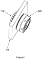
- FIGS 1 to 3 show various sections of various aspects of the optical fibre connector system 100 disclosed herein.
- the system 100 illustrative of this embodiment comprises an adapter 110 with an adapter body 112, the adapter body 112 of the adapter possesses a ring-shaped raised edge 114 surrounding and extending from one end of the adapter body 112.
- the connector system 100 depicted in the drawings can be installed onto the opening on the housing. More specifically, the raised edge 114 possesses a first connecting surface 116 for connecting to one side of the housing wall 10, the locking ring possessing a second connecting surface 122 for connecting to the opposite side of said wall 10.
- the interaction between the adapter 110 and the locking ring 120 compresses a sealing component such as an "O" ring 130 between the first connecting surface 116 and said wall 10, thus providing a sealed connection.
- the adapter body 112 possesses a first locking component 140 extending from the adapter body 112. More specifically, the first locking component 140 of the connector system 100 shown comprises two protruding locking sections 140a and 140b, the protruding locking sections 140a and 140b extending from the end of the cylindrical adapter body 112 opposite to that which possesses the raised edge 114, thus separating the first locking component 140 from the raised edge 114.
- the adapter body 112 is inserted into the housing wall 10 via opening 12, resulting in the "O" ring 130 being positioned between the connecting surface 116 of the raised edge 114 and the surface of said wall 10.
- the locking ring 120 is positioned on the adapter body 112.
- the locking ring 120 possesses a second locking component 150, that second locking component 150 being constructed such that by partially rotating the locking ring 120 relative to the adapter body 112 bringing it into contact with the first locking component 140 results in the positioning of the first connecting surface 116 at a pre-set distance from the second connecting surface 122.
- the locking ring 120 is rotated less than 360 degrees in order to secure the adapter 110 and seal it to the wall 10; additionally, in the embodiment depicted, rotation of 90 degrees or less allows locking and sealing of the adapter 110.
- the adapter 110 and locking ring 120 of the system 100 shown in the drawings possessing a first locking component 140 and a second locking component 150, the interaction between the first locking component 140 and the second locking component 150 positions the first connecting surface 116 and the second connecting surface 122, allowing the intended compression of said "O" ring 130 to be achieved, the angle of rotation of the locking ring 120 being less than 90 degrees.
- the connector system 100 is used to connect external optical cable (for instance, optical cables from external equipment external to the housing) to optical cable within the housing 10.
- the external optical cable is contained within the adapter 110 and carries the optical signal to the housing 10, the optical fibre connector system 100 allowing that signal to be transmitted from an external optical cable to another optical cable within the housing 10.
- the connector system 100 is hardened or strengthened. Such hardening or strengthening means that the adapter 110 of the connector is suitable for use in outdoor environments. For instance, the "O" ring 130 is compressed in position by the adapter 110 and the locking ring 120, achieving the desired environmental seal, thereby preventing axial and/or radial entry of damp/water.
- the said connector system 100 revealed is used to achieve an IP68 grade seal.
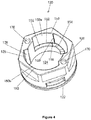
- Figures 4 to 6 further depict various aspects of the locking ring 120 shown in figures 1 to 3 , figure 7 depicting an embodiment of the adapter 110.
- the locking ring 120 has a central opening 124, that central opening 124 being constructed such that it holds the adapter body 112 shown in figure 3 .
- the second locking component 150 extends into the central opening 124 of the locking ring 120.
- the locking component possesses a first and second protruding locking sections 150a and 150b, which protrude radially into the central opening 124.
- the central opening 124 further delimits a slot 126 extending axially from the connecting surface 122 to the end opposite the locking ring 120.
- the slot 126 is delimited by the axial side 128 of the protruding locking sections 150a and 150b of the second locking component 150, its size and shape corresponding to that of the protruding locking sections 140a and 140b of the first locking component 140 of the adapter 110. This allows the protruding locking sections 140a and 140b to slide along the slot 126 as the locking ring 120 rotates around the adapter body 112 as shown in figure 3 . As a result of this, the locking ring 120 rotates relative to the adapter body 110, causing the first locking component 140 of the adapter 110 to come into contact with the second locking component 150 of the locking ring 120.
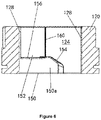
- each of the protruding locking sections 150a and 150b of the second locking component 150 is delimited by the locking surface 152; when the locking ring 120 is rotated relative to the adapter 110, that locking surface 152 connects with the locking surface 142 corresponding to the protruding locking sections 140a and 140b of the first locking component 140 extending from the adapter body 112.
- the locking surface 152 comprises an angled or slanted first section 154 and a second section 156 more or less parallel to the connecting surface 122.
- the locking surfaces 142 of the protruding locking sections 140a and 140b of the first locking component 140 connect with the slanted first section 154, as a result of which, as the locking surface 142 slides upwards along the angled first section 154, it causes the connecting surface 116 of the adapter 110 and the connecting surface 122 of the locking ring 120 to move relative to each other in an axial direction. As the locking ring 120 continues to rotate, the locking surface 142 connects with the second section 156.
- the second section 156 of the protruding locking sections 150a and 150b of the second locking component 150 is axially positioned, allowing the positioning of the first and second connecting surfaces 116 and 122 at pre-set distances from each other.
- the axial distance between connecting surfaces 116 and 122 depends on the thickness of the wall 10 and the amount of compression required to be exerted on the "O" ring 130.
- the stepped section 158 is located between the second section 156 of the locking surface 152 and the slanting first section 154.
- the protruding locking sections 140a and 140b of the first locking component 140 are positioned axially between the axial sides 128 of the stepped sections 158 of the protruding locking sections 150a and 150b of the second locking component.
- the stepped sections 158 lock the protruding locking sections 140a and 140b of the first locking component 140 in place, and prevent the rotation of the locking ring 120 in the opposite direction.
- the "clicking" (snapping) that occurs provides an indication to the operator that the locking ring 120 has already been sufficiently rotated to cause it to lock into position.
- the ribbed section 160 extends radially inwards into the central opening 124.
- the ribbed section 160 is positioned such that it is adjacent to each of the stepped sections 158 of the locking surface 152, extending axially along the central opening 124.
- the protruding locking sections 140a and 140b of the first locking component 140 pass through the ribbed section 160, the force required to rotate the locking ring 120 is reduced, giving further indication to the operator that installation is complete.
- the ribbed section 160 is also capable of preventing rotation of the locking ring in the opposite direction.
- the first locking component 140 and second locking component 150 of the adapter 110 and locking ring 120 both extend around 1.5 mm.
- the protruding locking sections 140a and 140b of the first locking component 140 both extend radially outwards from the adapter body 112 by around 1.5 mm, while the protruding locking sections 150a and 150b of the second locking component 150 extend radially into the central opening 124 by around 1.5 mm.
- the central opening 124 is such that it has a first diameter d1 of around 14.5 mm delimited by the internal surfaces of the protruding locking sections 150a and 150b of the second locking component 150, while the internal surface of slot 126 delimits a second diameter d2 of around 17.5 mm.
- the second section 156 of locking component 150 delimits a width w of around 7.3 mm.
- the first locking component 140 and second locking component 150 are arranged such that locking surface 142 connects with the second section 156 of locking surface 152, as a result of which, when locking ring 120 is rotated by a certain locking angle ⁇ the locking ring 120 becomes locked in position relative to the adapter 110.
- the locking rotation angle ⁇ is less than 360 degrees.
- the locking ring 120 becomes locked at an angle of rotation of less than 90 degrees, and in the embodiment shown in the drawings, the locking angle ⁇ is around 85 degrees to 87 degrees.
- the adapter 110 includes a module that locks the adapter 110 in position within the housing 10 and that prevents the adapter 110 from rotating once the locking ring 120 of the adapter has been rotated into position.
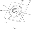
- Key 180 extends beneath the raised edge 114 of the adapter body 112. Furthermore, raised edge 114 delimits two flat sections 182 on its opposite side. Key 180 is contained within the slot 14 formed by the opening 12 extending through the housing 10. In the embodiment shown in figures 7 and 8 , the opening 12 is enclosed by the sleeve ring 16 extending across the external surface of the housing 10. The sleeve ring 16 delimits the flat section 18 that interacts with the flat section 182 of the raised edge 114.
- the "O" ring 130 When the adapter 110 is inserted into the opening 12, the "O" ring 130 is positioned between the connecting surface 116 of the raised edge 114 and the wall of the housing 10. Due to the sleeve ring 16 extending from the housing 10, it is not possible to see the "O" ring 130 from the side, and additionally, the capacity of the seal of the connector system 100 to resist lateral loading is improved.
- Figure 10 is yet another sectional view showing various aspects of the connector system 100. As mentioned above, in certain embodiments of this connector system 100, it is arranged in a manner allowing connection of optical cables.
- the locking ring 120 interacts with the adapter 110 to tightly secure the connector system 100 within the opening 12 in the housing 10.
- the "O" ring 130 is compressed between the connecting surface 116 of the raised edge 114 and the outer side wall of the housing 10, the connecting surface 122 of the locking ring 120 connecting with the inner side wall of the housing 10.
- the connecting surfaces 116 and 122 are positioned at a pre-set distance allowing satisfactory compression of the "O" ring 130.
- the first end of the adapter 110 contains a dust cap 210, that dust cap 210 being sealed by the "O" ring 212.
- the adapter body 112 contains an internal adapter 216, that internal adapter 216 possessing a protruding section 218 extending through the opening 144 of the protruding locking sections 140a and 140b of the first locking component 140.
- One end of the internal adapter 216 is contained within the retention sections 220 and 222 of the retention sleeve tube 224, the opposite end of said internal adapter containing the optical fibre connector 230.
- the locking ring 120 possesses a hexagonal shape making rotation of the locking ring 120 convenient using a spanner.
- holes 170 extend axially into the end of the locking ring 120 opposite to the connecting surface 122. These holes 170 are provided such that the dowel pins of installation tool 240 fit into them.
- Figure 11 depicts an embodiment of the installation tool 240, that installation tool 240 comprising a cylindrical body 242 with dowel pins 244, those dowel pins 244 extending axially from the cylindrical body 242.
- the dowel pins 244 are constructed such that they fit into holes 170 in the locking ring 120.
- the hexagonal end section 246 is designed in relation to the dowel pins 244 in a manner that, when the dowel pins 244 are fitted into the holes 170, a spanner can be used to rotate the installation tool 240 and the locking ring 120.
- Figure 12 is a sectional view of the connector system 100, wherein the installation tool 240 has already been connected to the locking ring.
- the cylindrical body 242 delimits the opening 248 capable of containing the internal adapter 216.
- the dowel pins 244 are fitted into the holes 170, in order to allow rotation of the installation tool 240 to rotate the locking ring 120.
Landscapes
- Physics & Mathematics (AREA)
- General Physics & Mathematics (AREA)
- Optics & Photonics (AREA)
- Mechanical Coupling Of Light Guides (AREA)
Description
- This Application asserts a claim on the rights claimed in
Chinese patent application 201420700716.8 - In overall terms, this disclosure relates to a type of connector system, more specifically an optical fibre connector of a type of connector system.
- Optical cables are widely used for the transmission of optical signals thus allowing high speed transmission of data. Optical cables generally comprise: one or more optical fibres, one or more buffer components surrounding the optical fibres, a reinforced layer surrounding said one or more buffer components and an external protective cover. Optical fibres are for the purpose of carrying optical signals. A typical optical fibre includes an internal core component surrounded by an encapsulating layer, the encapsulating layer being covered by a coating layer. Said buffer component (either a loose or tight buffer tube) is used to enclose and protect the coated optical fibre. The reinforced layer increases the mechanical strength of the optical cable, thus preventing strain being exerted on the optical fibre during installation or during subsequent processes. Examples of reinforced layers include aramid yarn, steel and epoxy reinforced glass roving. The external protective cover prevents damage due to crushing, abrasion and other physical damage. The external protective cover also prevents chemical damage (for instance by ozone, alkalis or acids).
- Optical cable connector systems are useful in allowing in-situ connection and disconnection of optical cables where splicing is not necessary. A typical optical cable connector system connecting two optical cables includes optical fibre connectors installed at the ends of the optical cables, and an adapter that couples the optical fibre connectors together both optically and mechanically. Optical fibre connectors typically consist of an insertion core which supports the optical cable at its end. Typically, the end surface of the insertion core is at an angle and polished. The adapter includes a coaxial alignment port (such as a socket) capable of containing the optical fibre connectors requiring connection. The adapter includes an internal sleeve tube; when the connector is inserted into the said port of the adapter, said internal sleeve tube accommodates and aligns with the insertion core of the said optical fibre connector. When the insertion core and the optical fibre with which it is connected are aligned correctly within the sleeve tube of the optical fibre adapter, the optical fibre signal can be transmitted from one optical fibre to the next optical fibre. Typically, adapters also include mechanical securing devices to ensure that the optical fibre connector is mechanically retained within the adapter.
- Typically, the housing wall of an MST or OTE housing (enclosure) in the adapter is captured by a raised edge on the adapter for instance in an arrangement such as a threaded nut fixing, the optical fibre connector system being installed within the housing by passing through an opening of a suitable size. The interaction between the raised edge of the adapter and the nut compresses a component, for instance a sealing "O" ring, thus achieving a sealed connection.
- Our intention was to improve the optical fibre connector system.
US 2009/305542 A1 discloses a waterproof connector to be connected to a mating connector. The waterproof connector includes a connector member to be connected to an adapter member; a connecting member to be connected to a cylindrical portion of a mating connector by rotation; and a main body portion. The connector member is able to slide along a facing direction of the connectors in a given range. - According to one aspect of this invention, it provides a kit according to claim 1.
- According to one illustrative embodiment of this invention, the adapter body is more or less cylindrical, the first locking component possessing a first protruding locking section and second protruding locking section extending radially from the adapter body.
- According to one illustrative embodiment of this invention, the first locking component includes a first locking surface.
- According to one illustrative embodiment of this invention, the second locking component includes a second locking surface being constructed such that it may connect with the first locking surface.
- According to one illustrative embodiment of this invention, the second locking surface includes a first section at an angle to the second connecting surface and a second section that is parallel to the second connecting surface.
- According to one illustrative embodiment of this invention, said second locking surface includes a stepped section between said first section and said second section.
- In one illustrative embodiment of this invention, the connector system further includes a ribbed section adjacent to said stepped section, said ribbed section extending radially inwards into the central opening of said locking ring.
- According to one illustrative embodiment of this invention, said locking ring delimits the central opening of said adapter body contained therein, while the second locking component protrudes radially inwards into said central opening.
- According to one illustrative embodiment of this invention, the central opening of the locking ring is delimited by an axial slot constructed such that it contains said first locking component.
-
-
Figure 1 is a 3-dimensional exploded view of various aspects of the optical fibre connector disclosed here; -
Figure 2 is another exploded view of the optical fibre connector depicted infigure 1 ; -
Figure 3 is a perspective drawing of the components shown infigure 1 andfigure 2 connected together; -
Figure 4 is a perspective drawing of one embodiment of the locking ring of the optical fibre connector system shown infigures 1 to 3 ; -
Figure 5 is an end elevation drawing of the locking ring shown infigure 4 ; -
Figure 6 is a cut-away side view of the locking ring shown infigure 4 andfigure 5 ; -
Figure 7 is a perspective drawing of one embodiment of the adapter of the optical fibre connector system shown infigures 1 to 3 ; -
Figure 8 is a partial perspective drawing of the optical fibre housing shown infigures 1 to 3 ; -
Figure 9 is a perspective drawing of the part of the optical fibre housing shown infigure 8 which accommodates the adapter shown infigure 7 ; -
Figure 10 provides a further sectional view of the various aspects of the optical fibre system disclosed herein; -
Figure 11 is a perspective drawing of the various aspects of the installation tool disclosed herein; and -
Figure 12 is a sectional view of the installation tool shown infigure 11 connected to the optical fibre connector system shown infigure 10 . - In the following detailed description, reference is made to the accompanying drawings which form a part hereof, and the drawings are shown by way of illustration of specific embodiments of the invention. In this respect, where terms such as "top", "bottom", "front" or "back" are used in the description, reference should be made to the drawing or drawings to which they apply. Due to it being possible to orientate the components referred to in the embodiments in a number of different directions, the terms of direction are only used for descriptive purposes, and should not be seen as being in any way restrictive. It should be appreciated that, other embodiments and any modification of the structure or logic without departing from the scope of this invention would be possible. In view of this, the following detailed description should not be understood as restricting the scope of this disclosure.
- For instance, the optical cables used in communication are commonly connected to one another using a wide variety of types of connectors. Optical cables are widely used for the high-speed transmission of data via the transmission of optical signals. Optical cables generally comprise: (1) one or more optical fibres; (2) one or more buffer components surrounding the optical fibres; (3) a reinforced layer surrounding said one or more buffer components; and (4) an external protective cover. Optical fibres are for the purpose of carrying optical signals. A typical optical fibre includes an internal core component surrounded by an encapsulating layer, the encapsulating layer being covered by a coating layer. The aforementioned buffer component (either a loose or tight buffer tube) is used to enclose and protect the coated optical fibre. The reinforced layer increases the mechanical strength of the optical cable, thus preventing strain being exerted on the optical fibre during installation or during subsequent processes. Examples of reinforced layers include aramid yarn, steel and epoxy reinforced glass roving. The external protective cover prevents damage due to crushing, abrasion and other physical damage. The external protective cover also prevents chemical damage (for instance by ozone, alkalis or acids).
- Optical cable connector systems are useful in allowing in-situ connection and disconnection of optical cables where splicing is not necessary. A typical optical cable connector system connecting two optical cables include optical fibre connectors installed at the ends of the optical cables, and an optical fibre adapter that couples the optical fibre connectors together both optically and mechanically. Optical fibre connectors typically consist of an insertion core which supports the optical cable at its end. Typically, the end surface of the insertion core is at an angle and polished. The optical fibre adapter includes a coaxial alignment port (such as a socket) capable of containing the optical fibre connectors requiring connection. The optical fibre adapter includes an internal sleeve tube; when the connector is inserted into the port of the optical fibre adapter, said internal sleeve tube accommodates and aligns with the insertion core of the said optical fibre connector. When the insertion core and the optical fibre with which it is connected are aligned correctly within the sleeve tube of the optical fibre adapter, the optical fibre signal can be transmitted from one optical fibre to the next optical fibre. Typically, adapters also include mechanical securing devices to ensure that the optical fibre connector is mechanically retained within the adapter.
-
Figures 1 to 3 show various sections of various aspects of the opticalfibre connector system 100 disclosed herein. Thesystem 100 illustrative of this embodiment comprises anadapter 110 with anadapter body 112, theadapter body 112 of the adapter possesses a ring-shaped raisededge 114 surrounding and extending from one end of theadapter body 112. By clamping thewall 10 of a housing such as an MST or OTE housing between the adapter's raisededge 114 and thelocking ring 120 of theadapter 110, theconnector system 100 depicted in the drawings can be installed onto the opening on the housing. More specifically, the raisededge 114 possesses a first connectingsurface 116 for connecting to one side of thehousing wall 10, the locking ring possessing a second connectingsurface 122 for connecting to the opposite side of saidwall 10. In the embodiment shown in the drawing, the interaction between theadapter 110 and thelocking ring 120 compresses a sealing component such as an "O"ring 130 between the first connectingsurface 116 and saidwall 10, thus providing a sealed connection. - Many of the connector systems of the current art rely on a threaded nut, rather than a
locking ring 120 such as that shown in the drawing, and when connections are made relying on the current art, the nut is contained within the adapter body by a threaded connection, rotation of the nut tightening the nut on the adapter's raised edge thus compressing the "O" ring. However, due to the general lack of space within the housing, rotation of the nut by a number of turns in order to achieve the intended seal by tightening the nut sufficiently presents difficulties and takes time. Furthermore, it is difficult to determine at what stage the nut has been tightened sufficiently, and generally a torque wrench is required to determine that an appropriate level of torque has been applied. According to this invention, theadapter body 112 possesses afirst locking component 140 extending from theadapter body 112. More specifically, thefirst locking component 140 of theconnector system 100 shown comprises two protrudinglocking sections locking sections cylindrical adapter body 112 opposite to that which possesses the raisededge 114, thus separating thefirst locking component 140 from the raisededge 114. As shown infigure 2 , theadapter body 112 is inserted into thehousing wall 10 viaopening 12, resulting in the "O"ring 130 being positioned between the connectingsurface 116 of the raisededge 114 and the surface of saidwall 10. As shown infigure 3 , thelocking ring 120 is positioned on theadapter body 112. Thelocking ring 120 possesses asecond locking component 150, thatsecond locking component 150 being constructed such that by partially rotating thelocking ring 120 relative to theadapter body 112 bringing it into contact with thefirst locking component 140 results in the positioning of the first connectingsurface 116 at a pre-set distance from the second connectingsurface 122. In certain embodiments, thelocking ring 120 is rotated less than 360 degrees in order to secure theadapter 110 and seal it to thewall 10; additionally, in the embodiment depicted, rotation of 90 degrees or less allows locking and sealing of theadapter 110. - In other words, it is no longer necessary to rotate a nut repeatedly in order to tighten the adapter so as to compress the "O" ring on the housing, the
adapter 110 and lockingring 120 of thesystem 100 shown in the drawings possessing afirst locking component 140 and asecond locking component 150, the interaction between thefirst locking component 140 and thesecond locking component 150 positions the first connectingsurface 116 and the second connectingsurface 122, allowing the intended compression of said "O"ring 130 to be achieved, the angle of rotation of thelocking ring 120 being less than 90 degrees. - In certain embodiments, the
connector system 100 is used to connect external optical cable (for instance, optical cables from external equipment external to the housing) to optical cable within thehousing 10. The external optical cable is contained within theadapter 110 and carries the optical signal to thehousing 10, the opticalfibre connector system 100 allowing that signal to be transmitted from an external optical cable to another optical cable within thehousing 10. As a result of this, in certain embodiments, theconnector system 100 is hardened or strengthened. Such hardening or strengthening means that theadapter 110 of the connector is suitable for use in outdoor environments. For instance, the "O"ring 130 is compressed in position by theadapter 110 and thelocking ring 120, achieving the desired environmental seal, thereby preventing axial and/or radial entry of damp/water. In certain embodiments, the saidconnector system 100 revealed is used to achieve an IP68 grade seal. -
Figures 4 to 6 further depict various aspects of thelocking ring 120 shown infigures 1 to 3 ,figure 7 depicting an embodiment of theadapter 110. Thelocking ring 120 has acentral opening 124, thatcentral opening 124 being constructed such that it holds theadapter body 112 shown infigure 3 . Referring tofigures 4 to 6 , thesecond locking component 150 extends into thecentral opening 124 of thelocking ring 120. In the embodiment depicted in the drawings, the locking component possesses a first and secondprotruding locking sections central opening 124. - The
central opening 124 further delimits aslot 126 extending axially from the connectingsurface 122 to the end opposite thelocking ring 120. Theslot 126 is delimited by theaxial side 128 of the protrudinglocking sections second locking component 150, its size and shape corresponding to that of the protrudinglocking sections first locking component 140 of theadapter 110. This allows the protrudinglocking sections slot 126 as thelocking ring 120 rotates around theadapter body 112 as shown infigure 3 . As a result of this, thelocking ring 120 rotates relative to theadapter body 110, causing thefirst locking component 140 of theadapter 110 to come into contact with thesecond locking component 150 of thelocking ring 120. - In the embodiment revealed, each of the protruding
locking sections second locking component 150 is delimited by the lockingsurface 152; when thelocking ring 120 is rotated relative to theadapter 110, that lockingsurface 152 connects with the lockingsurface 142 corresponding to the protrudinglocking sections first locking component 140 extending from theadapter body 112. The lockingsurface 152 comprises an angled or slantedfirst section 154 and asecond section 156 more or less parallel to the connectingsurface 122. As a result of this, when thelocking ring 120 is rotated, the locking surfaces 142 of the protrudinglocking sections first locking component 140 connect with the slantedfirst section 154, as a result of which, as the lockingsurface 142 slides upwards along the angledfirst section 154, it causes the connectingsurface 116 of theadapter 110 and the connectingsurface 122 of thelocking ring 120 to move relative to each other in an axial direction. As thelocking ring 120 continues to rotate, the lockingsurface 142 connects with thesecond section 156. Thesecond section 156 of the protrudinglocking sections second locking component 150 is axially positioned, allowing the positioning of the first and second connectingsurfaces surfaces wall 10 and the amount of compression required to be exerted on the "O"ring 130. - In the embodiment depicted, the stepped
section 158 is located between thesecond section 156 of the lockingsurface 152 and the slantingfirst section 154. When the lockingsurface 142 of thefirst locking component 140 rotates relative to thelocking ring 120 and passes the angledfirst section 154, the protrudinglocking sections first locking component 140 are positioned axially between theaxial sides 128 of the steppedsections 158 of the protrudinglocking sections sections 158 lock the protrudinglocking sections first locking component 140 in place, and prevent the rotation of thelocking ring 120 in the opposite direction. Furthermore, as the protrudinglocking sections first locking component 140 pass the steppedsections 158 and come into contact with thesecond section 156 of the lockingsurface 152, the "clicking" (snapping) that occurs provides an indication to the operator that thelocking ring 120 has already been sufficiently rotated to cause it to lock into position. - Furthermore, in the embodiment shown in
figures 4 to 6 , theribbed section 160 extends radially inwards into thecentral opening 124. Theribbed section 160 is positioned such that it is adjacent to each of the steppedsections 158 of the lockingsurface 152, extending axially along thecentral opening 124. When the protrudinglocking sections first locking component 140 pass through theribbed section 160, the force required to rotate thelocking ring 120 is reduced, giving further indication to the operator that installation is complete. Once the lockingsurface 142 of thefirst locking component 140 has already connected with thesecond section 156 of thelocking component 150, theribbed section 160 is also capable of preventing rotation of the locking ring in the opposite direction. - In certain embodiments, the
first locking component 140 andsecond locking component 150 of theadapter 110 and lockingring 120 both extend around 1.5 mm. As a result of this, the protrudinglocking sections first locking component 140 both extend radially outwards from theadapter body 112 by around 1.5 mm, while the protrudinglocking sections second locking component 150 extend radially into thecentral opening 124 by around 1.5 mm. As depicted infigures 4 to 6 , thecentral opening 124 is such that it has a first diameter d1 of around 14.5 mm delimited by the internal surfaces of the protrudinglocking sections second locking component 150, while the internal surface ofslot 126 delimits a second diameter d2 of around 17.5 mm. Thesecond section 156 of lockingcomponent 150 delimits a width w of around 7.3 mm. - The
first locking component 140 andsecond locking component 150 are arranged such that lockingsurface 142 connects with thesecond section 156 of lockingsurface 152, as a result of which, when lockingring 120 is rotated by a certain locking angle θ the lockingring 120 becomes locked in position relative to theadapter 110. In certain embodiments, the locking rotation angle θ is less than 360 degrees. In certain embodiments, thelocking ring 120 becomes locked at an angle of rotation of less than 90 degrees, and in the embodiment shown in the drawings, the locking angle θ is around 85 degrees to 87 degrees. - Referring to
figures 7 to 9 , theadapter 110 includes a module that locks theadapter 110 in position within thehousing 10 and that prevents theadapter 110 from rotating once the lockingring 120 of the adapter has been rotated into position.Key 180 extends beneath the raisededge 114 of theadapter body 112. Furthermore, raisededge 114 delimits twoflat sections 182 on its opposite side.Key 180 is contained within theslot 14 formed by theopening 12 extending through thehousing 10. In the embodiment shown infigures 7 and8 , theopening 12 is enclosed by thesleeve ring 16 extending across the external surface of thehousing 10. Thesleeve ring 16 delimits theflat section 18 that interacts with theflat section 182 of the raisededge 114. When theadapter 110 is inserted into theopening 12, the "O"ring 130 is positioned between the connectingsurface 116 of the raisededge 114 and the wall of thehousing 10. Due to thesleeve ring 16 extending from thehousing 10, it is not possible to see the "O"ring 130 from the side, and additionally, the capacity of the seal of theconnector system 100 to resist lateral loading is improved. -
Figure 10 is yet another sectional view showing various aspects of theconnector system 100. As mentioned above, in certain embodiments of thisconnector system 100, it is arranged in a manner allowing connection of optical cables. In the embodiment shown infigure 10 , thelocking ring 120 interacts with theadapter 110 to tightly secure theconnector system 100 within theopening 12 in thehousing 10. The "O"ring 130 is compressed between the connectingsurface 116 of the raisededge 114 and the outer side wall of thehousing 10, the connectingsurface 122 of thelocking ring 120 connecting with the inner side wall of thehousing 10. As shown in the drawings, where thelocking ring 120 has already been rotated until thefirst locking component 140 andsecond locking component 150 connect, the connectingsurfaces ring 130. - The first end of the
adapter 110 contains adust cap 210, thatdust cap 210 being sealed by the "O"ring 212. - In this manner, the
adapter 110 remains sealed until the adapter is used to connect thehousing 10 to external optical cables, and as such, it is possible to include adust cap strap 214 to retain thedust cap 212. Theadapter body 112 contains aninternal adapter 216, thatinternal adapter 216 possessing a protrudingsection 218 extending through theopening 144 of the protrudinglocking sections first locking component 140. One end of theinternal adapter 216 is contained within theretention sections 220 and 222 of theretention sleeve tube 224, the opposite end of said internal adapter containing theoptical fibre connector 230. - Referring back to
figures 4 and5 , thelocking ring 120 possesses a hexagonal shape making rotation of thelocking ring 120 convenient using a spanner. For convenience of installation in restricted spaces, holes 170 extend axially into the end of thelocking ring 120 opposite to the connectingsurface 122. Theseholes 170 are provided such that the dowel pins ofinstallation tool 240 fit into them.Figure 11 depicts an embodiment of theinstallation tool 240, thatinstallation tool 240 comprising acylindrical body 242 withdowel pins 244, those dowel pins 244 extending axially from thecylindrical body 242. The dowel pins 244 are constructed such that they fit intoholes 170 in thelocking ring 120. Thehexagonal end section 246 is designed in relation to the dowel pins 244 in a manner that, when the dowel pins 244 are fitted into theholes 170, a spanner can be used to rotate theinstallation tool 240 and thelocking ring 120. -
Figure 12 is a sectional view of theconnector system 100, wherein theinstallation tool 240 has already been connected to the locking ring. - More specifically, the
cylindrical body 242 delimits the opening 248 capable of containing theinternal adapter 216. The dowel pins 244 are fitted into theholes 170, in order to allow rotation of theinstallation tool 240 to rotate thelocking ring 120. - Various modifications and alternative embodiments of the present disclosure will be apparent to those skilled in the art without departing from the scope of the appended claims, and it is to be understood that the scope of this invention should not be unduly restricted to the embodiments indicated in the diagrams in this text.
-
- 10
- housing wall
- 12
- opening in housing wall
- 14
- slot
- 16
- sleeve ring surrounding opening
- 100
- optical fibre connector system
- 110
- adapter
- 112
- adapter body
- 114
- ring-shaped raised edge
- 116
- first connecting surface
- 120
- locking ring
- 122
- second connecting surface
- 124
- central opening in locking ring
- 126
- slot in locking ring
- 128
- side section of protruding locking section
- 130
- "O" ring
- 140
- first locking component
- 140a
- adapter protruding locking section
- 140b
- adapter protruding locking section
- 142
- locking surface
- 150
- second locking component
- 150a
- protruding locking section of locking ring
- 150b
- protruding locking section of locking ring
- 152
- locking surface
- 154
- first slanted section of locking surface
- 156
- second section of locking surface
- 158
- stepped section
- 160
- ribbed section
- 170
- holes in locking ring
- 180
- adapter key
- 182
- flat section of raised edge
- 210
- dust cap
- 212
- "O" ring
- 214
- dust cap strap
- 216
- internal adapter
- 218
- protruding section of internal adapter
- 220
- retention section
- 222
- retention section
- 224
- sleeve tube
- 230
- optical fibre connector
- 240
- installation tool
- 242
- installation tool cylindrical body
- 244
- installation tool dowel pin
- 246
- installation tool hexagonal end section
- 248
- installation tool body opening
Claims (9)
- A kit of parts consisting of:an optical fibre connector system (100);an "O" ring (130); anda housing comprising an opening (12) and a wall (10); an optical fibre connector system (100) comprising:an adapter (110) comprising an adapter body (112) with a first locking component (140);the adapter body (112) possessing a ring-shaped raised edge (114) surrounding and extending from one end of the adapter body (112), the ring-shaped raised edge (114) possessing a first connecting surface (116); anda locking ring (120), the locking ring (120) being constructed such that it can be installed around the adapter body (112) said locking ring (120) possessing a second connecting surface (122) and a second locking component (150);wherein when the adapter body (112) is inserted into the housing wall (10) via the opening (12), the "O" ring (130) is positioned between the first connecting surface (116) and the surface of the wall (10);the second locking component (150) being constructed such that by partially rotating the locking ring (120) relative to the adapter body (112) brings the second locking component (150) into contact with the first locking component (140) resulting in the positioning of the first connecting surface (116) at a pre-set distance from the second connecting surface (122); the pre-set distance corresponding to a distance for compressing the "O" ring (130) between the first connecting surface and the housing wall (10) positioned between the first connecting surface and the second connecting surface;said first locking component and said second locking component being constructed such that they connect together when said locking ring is rotated by an angle of 90 degrees or less than 90 degrees relative to the adapter body, thus allowing positioning of the first connecting surface at the pre-set distance from the second connecting surface.
- The kit of parts according to claim 1, whereinthe adapter body is cylindrical; additionallythe said first locking component includes a first protruding locking section and a second protruding locking section (140a, 140b) extending radially from the said adapter body.
- The kit of parts according to claim 1, wherein said first locking component includes a first locking surface (142).
- The kit of parts according to claim 3, wherein said second locking component includes a second locking surface (152) being constructed such that this may connect with the said first locking surface.
- The kit of parts according to claim 4, wherein said second locking surface includes a first section (154) at an angle to the second connecting surface (122) and a second section (156) that is parallel to the second connecting surface (122).
- The kit of parts according to claim 5, wherein said second locking surface includes a stepped section (158) between said first section and said second section.
- The kit of parts according to claim 6, wherein the connector system further includes a ribbed section (160) adjacent to said stepped section, said ribbed section extending radially inwards into a central opening (124) of said locking ring.
- The kit of parts according to claim 1, wherein
said locking ring delimits a central opening (124) of said adapter body contained therein; and additionally, the second locking component protrudes radially inwards into said central opening. - The kit of parts according to claim 8, wherein the central opening of the said locking ring is delimited by an axial slot (126) constructed such that it contains said first locking component.
Applications Claiming Priority (2)
| Application Number | Priority Date | Filing Date | Title |
|---|---|---|---|
| CN201420700716.8U CN204359965U (en) | 2014-11-20 | 2014-11-20 | Connector system |
| PCT/CN2015/095191 WO2016078613A1 (en) | 2014-11-20 | 2015-11-20 | Optical fiber connector |
Publications (3)
| Publication Number | Publication Date |
|---|---|
| EP3223050A1 EP3223050A1 (en) | 2017-09-27 |
| EP3223050A4 EP3223050A4 (en) | 2018-07-11 |
| EP3223050B1 true EP3223050B1 (en) | 2022-01-12 |
Family
ID=53261427
Family Applications (1)
| Application Number | Title | Priority Date | Filing Date |
|---|---|---|---|
| EP15860861.2A Active EP3223050B1 (en) | 2014-11-20 | 2015-11-20 | Kit of parts |
Country Status (5)
| Country | Link |
|---|---|
| US (2) | US10551571B2 (en) |
| EP (1) | EP3223050B1 (en) |
| CN (1) | CN204359965U (en) |
| ES (1) | ES2908865T3 (en) |
| WO (1) | WO2016078613A1 (en) |
Families Citing this family (12)
| Publication number | Priority date | Publication date | Assignee | Title |
|---|---|---|---|---|
| CN204359965U (en) * | 2014-11-20 | 2015-05-27 | 泰科电子(上海)有限公司 | Connector system |
| KR102574618B1 (en) * | 2016-01-26 | 2023-09-05 | 튜미 인코포레이티드 | strap attachment |
| CN113196124B (en) * | 2018-10-16 | 2023-03-17 | 扇港元器件股份有限公司 | Springless retention structure for entry protected hybrid connector assembly |
| US12061366B2 (en) | 2019-05-17 | 2024-08-13 | Commscope Technologies Llc | Mechanical connection interface |
| CN110320610A (en) * | 2019-06-19 | 2019-10-11 | 深圳市维度科技有限公司 | Fiber adapter |
| TWM585910U (en) * | 2019-06-25 | 2019-11-01 | 大陸商安費諾光纖技術(深圳)有限公司 | Optical fibre connector |
| TWM584436U (en) * | 2019-07-03 | 2019-10-01 | 大陸商安費諾光纖技術(深圳)有限公司 | Optical fibre connector |
| TWM584437U (en) * | 2019-07-03 | 2019-10-01 | 大陸商安費諾光纖技術(深圳)有限公司 | Optical fibre connector |
| TWM584435U (en) * | 2019-07-03 | 2019-10-01 | 大陸商安費諾光纖技術(深圳)有限公司 | Optical fibre connector |
| WO2021041305A1 (en) | 2019-08-26 | 2021-03-04 | Commscope Technologies Llc | Fiber optic connectors and fiber optic connection systems |
| US10916391B1 (en) * | 2019-09-23 | 2021-02-09 | Glen Payne | Arc flash detection systems and components thereof |
| CN114114566B (en) * | 2021-10-09 | 2023-01-06 | 华为技术有限公司 | connection box |
Citations (1)
| Publication number | Priority date | Publication date | Assignee | Title |
|---|---|---|---|---|
| US20090305542A1 (en) * | 2008-06-04 | 2009-12-10 | Hirose Electric Co., Ltd. | Waterproof connector and waterproof apparatus using the same |
Family Cites Families (23)
| Publication number | Priority date | Publication date | Assignee | Title |
|---|---|---|---|---|
| US5668904A (en) * | 1996-07-25 | 1997-09-16 | Northwest Fiberoptic Technologies Inc. | Fiber optic cable connector apparatus and method |
| DE19901473A1 (en) | 1999-01-15 | 2000-07-20 | Delphi Tech Inc | Connector system for optical cables |
| US6648520B2 (en) | 2001-09-28 | 2003-11-18 | Corning Cable Systems Llc | Fiber optic plug |
| US6579014B2 (en) | 2001-09-28 | 2003-06-17 | Corning Cable Systems Llc | Fiber optic receptacle |
| US7146090B2 (en) | 2004-06-17 | 2006-12-05 | Corning Cable Systems Llc | Fiber optic cable and plug assembly |
| US20060045428A1 (en) | 2004-08-24 | 2006-03-02 | Thomas Theuerkorn | Fiber optic receptacle and plug assemblies |
| US7044650B1 (en) | 2004-10-22 | 2006-05-16 | Corning Cable Systems Llc | One-piece fiber optic receptacle having chamfer and alignment ribs |
| US7207727B2 (en) | 2004-10-22 | 2007-04-24 | Corning Cable Systems Llc | One-piece fiber optic receptacle |
| US7244066B2 (en) | 2005-02-25 | 2007-07-17 | Corning Cable Systems Llc | Fiber optic receptacle and plug assembly including alignment sleeve insert |
| US7264402B2 (en) | 2005-03-10 | 2007-09-04 | Corning Cable Systems Llc | Multi-fiber optic receptacle and plug assembly |
| US7568844B2 (en) | 2006-08-15 | 2009-08-04 | Corning Cable Systems Llc | Ruggedized fiber optic connector assembly |
| US7572065B2 (en) | 2007-01-24 | 2009-08-11 | Adc Telecommunications, Inc. | Hardened fiber optic connector |
| US7614797B2 (en) | 2007-01-24 | 2009-11-10 | Adc Telecommunications, Inc. | Fiber optic connector mechanical interface converter |
| US7744286B2 (en) | 2007-12-11 | 2010-06-29 | Adc Telecommunications, Inc. | Hardened fiber optic connection system with multiple configurations |
| JP4743724B2 (en) * | 2009-02-26 | 2011-08-10 | ヒロセ電機株式会社 | Waterproof connector and waterproof device using the waterproof connector |
| CN201425637Y (en) * | 2009-04-03 | 2010-03-17 | 深圳日海通讯技术股份有限公司 | Optical fiber connector |
| EP3249434B1 (en) | 2009-09-28 | 2021-11-24 | TE Connectivity Nederland B.V. | Sealing enclosure for a connector on a cable, such as a standardised fibre-optic connector |
| CN201540384U (en) * | 2009-10-13 | 2010-08-04 | 深圳日海通讯技术股份有限公司 | Optical fiber connector |
| EP2927720B1 (en) * | 2010-02-03 | 2018-10-17 | Tyco Electronics Nederland B.V. | Enclosure assembly for a connector, strain relief element, and method |
| WO2013077969A1 (en) | 2011-11-23 | 2013-05-30 | Adc Telecommunications, Inc. | Multi-fiber fiber optic connector |
| EP3158375A1 (en) | 2014-06-23 | 2017-04-26 | Tyco Electronics Raychem BVBA | Fiber optic connection system with fast coupling mechanism |
| CN204359965U (en) * | 2014-11-20 | 2015-05-27 | 泰科电子(上海)有限公司 | Connector system |
| EP3316013A4 (en) | 2015-06-23 | 2019-02-27 | ADC Telecommunications (Shanghai) Distribution Co., Ltd. | FIBER OPTIC CONNECTOR ASSEMBLY |
-
2014
- 2014-11-20 CN CN201420700716.8U patent/CN204359965U/en not_active Expired - Fee Related
-
2015
- 2015-11-20 ES ES15860861T patent/ES2908865T3/en active Active
- 2015-11-20 WO PCT/CN2015/095191 patent/WO2016078613A1/en not_active Ceased
- 2015-11-20 US US15/528,451 patent/US10551571B2/en active Active
- 2015-11-20 EP EP15860861.2A patent/EP3223050B1/en active Active
-
2020
- 2020-02-03 US US16/780,052 patent/US20200284993A1/en not_active Abandoned
Patent Citations (1)
| Publication number | Priority date | Publication date | Assignee | Title |
|---|---|---|---|---|
| US20090305542A1 (en) * | 2008-06-04 | 2009-12-10 | Hirose Electric Co., Ltd. | Waterproof connector and waterproof apparatus using the same |
Also Published As
| Publication number | Publication date |
|---|---|
| US20180143381A1 (en) | 2018-05-24 |
| EP3223050A1 (en) | 2017-09-27 |
| CN204359965U (en) | 2015-05-27 |
| WO2016078613A1 (en) | 2016-05-26 |
| US20200284993A1 (en) | 2020-09-10 |
| ES2908865T3 (en) | 2022-05-04 |
| US10551571B2 (en) | 2020-02-04 |
| EP3223050A4 (en) | 2018-07-11 |
Similar Documents
| Publication | Publication Date | Title |
|---|---|---|
| US20200284993A1 (en) | Optical fiber connector | |
| JP3240929U (en) | Fiber optic subassemblies and fiber optic connectors | |
| US9739951B2 (en) | Fiber-optic connection arrangement and adapter sleeve | |
| US11581679B2 (en) | Bayonet-type bundled RF connector assembly | |
| US8814441B2 (en) | Optical connector | |
| JP6567085B2 (en) | Plug protection cap, optical fiber connector assembly, fiber plug, and network device | |
| US7614797B2 (en) | Fiber optic connector mechanical interface converter | |
| US20200064561A1 (en) | Hardened converter and sealing shell for field terminated connector | |
| US9379488B2 (en) | Enclosure assembly for a connector, strain relief element, and method | |
| US5271080A (en) | Fiber optic cable entry connector | |
| CN212540781U (en) | Direct-insertion sealed optical fiber connector, connector and connector assembly | |
| EP3693773B1 (en) | Optical fiber connector and optical fiber connection assembly | |
| US8414313B2 (en) | Security shield and tool | |
| GB2470584A (en) | Cable end unit | |
| US5074636A (en) | Fiber optic cable entry connector | |
| US11495913B2 (en) | Optical fiber connector and optical fiber connector assembly | |
| US9575264B2 (en) | Optical fiber connector | |
| CN219266580U (en) | Fiber Optic Connectors and Fiber Optic Connector Assemblies | |
| CN223664809U (en) | A structure of an SC quick-connect adapter | |
| AU2015261569B2 (en) | Fibre-optic connecting arrangement and adapter sleeve | |
| CN114764167A (en) | Optical fiber connector and assembly thereof |
Legal Events
| Date | Code | Title | Description |
|---|---|---|---|
| STAA | Information on the status of an ep patent application or granted ep patent |
Free format text: STATUS: THE INTERNATIONAL PUBLICATION HAS BEEN MADE |
|
| PUAI | Public reference made under article 153(3) epc to a published international application that has entered the european phase |
Free format text: ORIGINAL CODE: 0009012 |
|
| STAA | Information on the status of an ep patent application or granted ep patent |
Free format text: STATUS: REQUEST FOR EXAMINATION WAS MADE |
|
| 17P | Request for examination filed |
Effective date: 20170619 |
|
| AK | Designated contracting states |
Kind code of ref document: A1 Designated state(s): AL AT BE BG CH CY CZ DE DK EE ES FI FR GB GR HR HU IE IS IT LI LT LU LV MC MK MT NL NO PL PT RO RS SE SI SK SM TR |
|
| AX | Request for extension of the european patent |
Extension state: BA ME |
|
| DAV | Request for validation of the european patent (deleted) | ||
| DAX | Request for extension of the european patent (deleted) | ||
| A4 | Supplementary search report drawn up and despatched |
Effective date: 20180608 |
|
| RIC1 | Information provided on ipc code assigned before grant |
Ipc: G02B 6/38 20060101AFI20180604BHEP |
|
| STAA | Information on the status of an ep patent application or granted ep patent |
Free format text: STATUS: EXAMINATION IS IN PROGRESS |
|
| RAP1 | Party data changed (applicant data changed or rights of an application transferred) |
Owner name: COMMSCOPE TELECOMMUNICATIONS (SHANGHAI) CO. LTD. |
|
| 17Q | First examination report despatched |
Effective date: 20191010 |
|
| GRAP | Despatch of communication of intention to grant a patent |
Free format text: ORIGINAL CODE: EPIDOSNIGR1 |
|
| STAA | Information on the status of an ep patent application or granted ep patent |
Free format text: STATUS: GRANT OF PATENT IS INTENDED |
|
| INTG | Intention to grant announced |
Effective date: 20210803 |
|
| GRAS | Grant fee paid |
Free format text: ORIGINAL CODE: EPIDOSNIGR3 |
|
| GRAA | (expected) grant |
Free format text: ORIGINAL CODE: 0009210 |
|
| STAA | Information on the status of an ep patent application or granted ep patent |
Free format text: STATUS: THE PATENT HAS BEEN GRANTED |
|
| AK | Designated contracting states |
Kind code of ref document: B1 Designated state(s): AL AT BE BG CH CY CZ DE DK EE ES FI FR GB GR HR HU IE IS IT LI LT LU LV MC MK MT NL NO PL PT RO RS SE SI SK SM TR |
|
| REG | Reference to a national code |
Ref country code: GB Ref legal event code: FG4D |
|
| REG | Reference to a national code |
Ref country code: CH Ref legal event code: EP |
|
| REG | Reference to a national code |
Ref country code: DE Ref legal event code: R096 Ref document number: 602015076477 Country of ref document: DE |
|
| REG | Reference to a national code |
Ref country code: IE Ref legal event code: FG4D |
|
| REG | Reference to a national code |
Ref country code: AT Ref legal event code: REF Ref document number: 1462764 Country of ref document: AT Kind code of ref document: T Effective date: 20220215 |
|
| REG | Reference to a national code |
Ref country code: ES Ref legal event code: FG2A Ref document number: 2908865 Country of ref document: ES Kind code of ref document: T3 Effective date: 20220504 |
|
| REG | Reference to a national code |
Ref country code: LT Ref legal event code: MG9D |
|
| REG | Reference to a national code |
Ref country code: NL Ref legal event code: MP Effective date: 20220112 |
|
| REG | Reference to a national code |
Ref country code: AT Ref legal event code: MK05 Ref document number: 1462764 Country of ref document: AT Kind code of ref document: T Effective date: 20220112 |
|
| PG25 | Lapsed in a contracting state [announced via postgrant information from national office to epo] |
Ref country code: NL Free format text: LAPSE BECAUSE OF FAILURE TO SUBMIT A TRANSLATION OF THE DESCRIPTION OR TO PAY THE FEE WITHIN THE PRESCRIBED TIME-LIMIT Effective date: 20220112 |
|
| PG25 | Lapsed in a contracting state [announced via postgrant information from national office to epo] |
Ref country code: SE Free format text: LAPSE BECAUSE OF FAILURE TO SUBMIT A TRANSLATION OF THE DESCRIPTION OR TO PAY THE FEE WITHIN THE PRESCRIBED TIME-LIMIT Effective date: 20220112 Ref country code: RS Free format text: LAPSE BECAUSE OF FAILURE TO SUBMIT A TRANSLATION OF THE DESCRIPTION OR TO PAY THE FEE WITHIN THE PRESCRIBED TIME-LIMIT Effective date: 20220112 Ref country code: PT Free format text: LAPSE BECAUSE OF FAILURE TO SUBMIT A TRANSLATION OF THE DESCRIPTION OR TO PAY THE FEE WITHIN THE PRESCRIBED TIME-LIMIT Effective date: 20220512 Ref country code: NO Free format text: LAPSE BECAUSE OF FAILURE TO SUBMIT A TRANSLATION OF THE DESCRIPTION OR TO PAY THE FEE WITHIN THE PRESCRIBED TIME-LIMIT Effective date: 20220412 Ref country code: LT Free format text: LAPSE BECAUSE OF FAILURE TO SUBMIT A TRANSLATION OF THE DESCRIPTION OR TO PAY THE FEE WITHIN THE PRESCRIBED TIME-LIMIT Effective date: 20220112 Ref country code: HR Free format text: LAPSE BECAUSE OF FAILURE TO SUBMIT A TRANSLATION OF THE DESCRIPTION OR TO PAY THE FEE WITHIN THE PRESCRIBED TIME-LIMIT Effective date: 20220112 Ref country code: BG Free format text: LAPSE BECAUSE OF FAILURE TO SUBMIT A TRANSLATION OF THE DESCRIPTION OR TO PAY THE FEE WITHIN THE PRESCRIBED TIME-LIMIT Effective date: 20220412 |
|
| PG25 | Lapsed in a contracting state [announced via postgrant information from national office to epo] |
Ref country code: PL Free format text: LAPSE BECAUSE OF FAILURE TO SUBMIT A TRANSLATION OF THE DESCRIPTION OR TO PAY THE FEE WITHIN THE PRESCRIBED TIME-LIMIT Effective date: 20220112 Ref country code: LV Free format text: LAPSE BECAUSE OF FAILURE TO SUBMIT A TRANSLATION OF THE DESCRIPTION OR TO PAY THE FEE WITHIN THE PRESCRIBED TIME-LIMIT Effective date: 20220112 Ref country code: GR Free format text: LAPSE BECAUSE OF FAILURE TO SUBMIT A TRANSLATION OF THE DESCRIPTION OR TO PAY THE FEE WITHIN THE PRESCRIBED TIME-LIMIT Effective date: 20220413 Ref country code: FI Free format text: LAPSE BECAUSE OF FAILURE TO SUBMIT A TRANSLATION OF THE DESCRIPTION OR TO PAY THE FEE WITHIN THE PRESCRIBED TIME-LIMIT Effective date: 20220112 Ref country code: AT Free format text: LAPSE BECAUSE OF FAILURE TO SUBMIT A TRANSLATION OF THE DESCRIPTION OR TO PAY THE FEE WITHIN THE PRESCRIBED TIME-LIMIT Effective date: 20220112 |
|
| PG25 | Lapsed in a contracting state [announced via postgrant information from national office to epo] |
Ref country code: IS Free format text: LAPSE BECAUSE OF FAILURE TO SUBMIT A TRANSLATION OF THE DESCRIPTION OR TO PAY THE FEE WITHIN THE PRESCRIBED TIME-LIMIT Effective date: 20220512 |
|
| REG | Reference to a national code |
Ref country code: DE Ref legal event code: R097 Ref document number: 602015076477 Country of ref document: DE |
|
| PG25 | Lapsed in a contracting state [announced via postgrant information from national office to epo] |
Ref country code: SM Free format text: LAPSE BECAUSE OF FAILURE TO SUBMIT A TRANSLATION OF THE DESCRIPTION OR TO PAY THE FEE WITHIN THE PRESCRIBED TIME-LIMIT Effective date: 20220112 Ref country code: SK Free format text: LAPSE BECAUSE OF FAILURE TO SUBMIT A TRANSLATION OF THE DESCRIPTION OR TO PAY THE FEE WITHIN THE PRESCRIBED TIME-LIMIT Effective date: 20220112 Ref country code: RO Free format text: LAPSE BECAUSE OF FAILURE TO SUBMIT A TRANSLATION OF THE DESCRIPTION OR TO PAY THE FEE WITHIN THE PRESCRIBED TIME-LIMIT Effective date: 20220112 Ref country code: EE Free format text: LAPSE BECAUSE OF FAILURE TO SUBMIT A TRANSLATION OF THE DESCRIPTION OR TO PAY THE FEE WITHIN THE PRESCRIBED TIME-LIMIT Effective date: 20220112 Ref country code: DK Free format text: LAPSE BECAUSE OF FAILURE TO SUBMIT A TRANSLATION OF THE DESCRIPTION OR TO PAY THE FEE WITHIN THE PRESCRIBED TIME-LIMIT Effective date: 20220112 Ref country code: CZ Free format text: LAPSE BECAUSE OF FAILURE TO SUBMIT A TRANSLATION OF THE DESCRIPTION OR TO PAY THE FEE WITHIN THE PRESCRIBED TIME-LIMIT Effective date: 20220112 |
|
| PLBE | No opposition filed within time limit |
Free format text: ORIGINAL CODE: 0009261 |
|
| STAA | Information on the status of an ep patent application or granted ep patent |
Free format text: STATUS: NO OPPOSITION FILED WITHIN TIME LIMIT |
|
| PG25 | Lapsed in a contracting state [announced via postgrant information from national office to epo] |
Ref country code: AL Free format text: LAPSE BECAUSE OF FAILURE TO SUBMIT A TRANSLATION OF THE DESCRIPTION OR TO PAY THE FEE WITHIN THE PRESCRIBED TIME-LIMIT Effective date: 20220112 |
|
| 26N | No opposition filed |
Effective date: 20221013 |
|
| PG25 | Lapsed in a contracting state [announced via postgrant information from national office to epo] |
Ref country code: SI Free format text: LAPSE BECAUSE OF FAILURE TO SUBMIT A TRANSLATION OF THE DESCRIPTION OR TO PAY THE FEE WITHIN THE PRESCRIBED TIME-LIMIT Effective date: 20220112 |
|
| PG25 | Lapsed in a contracting state [announced via postgrant information from national office to epo] |
Ref country code: MC Free format text: LAPSE BECAUSE OF FAILURE TO SUBMIT A TRANSLATION OF THE DESCRIPTION OR TO PAY THE FEE WITHIN THE PRESCRIBED TIME-LIMIT Effective date: 20220112 |
|
| REG | Reference to a national code |
Ref country code: CH Ref legal event code: PL |
|
| P01 | Opt-out of the competence of the unified patent court (upc) registered |
Effective date: 20230530 |
|
| REG | Reference to a national code |
Ref country code: BE Ref legal event code: MM Effective date: 20221130 |
|
| PG25 | Lapsed in a contracting state [announced via postgrant information from national office to epo] |
Ref country code: LI Free format text: LAPSE BECAUSE OF NON-PAYMENT OF DUE FEES Effective date: 20221130 Ref country code: IT Free format text: LAPSE BECAUSE OF FAILURE TO SUBMIT A TRANSLATION OF THE DESCRIPTION OR TO PAY THE FEE WITHIN THE PRESCRIBED TIME-LIMIT Effective date: 20220112 Ref country code: CH Free format text: LAPSE BECAUSE OF NON-PAYMENT OF DUE FEES Effective date: 20221130 |
|
| PG25 | Lapsed in a contracting state [announced via postgrant information from national office to epo] |
Ref country code: LU Free format text: LAPSE BECAUSE OF NON-PAYMENT OF DUE FEES Effective date: 20221120 |
|
| PG25 | Lapsed in a contracting state [announced via postgrant information from national office to epo] |
Ref country code: IE Free format text: LAPSE BECAUSE OF NON-PAYMENT OF DUE FEES Effective date: 20221120 |
|
| PG25 | Lapsed in a contracting state [announced via postgrant information from national office to epo] |
Ref country code: FR Free format text: LAPSE BECAUSE OF NON-PAYMENT OF DUE FEES Effective date: 20221130 Ref country code: BE Free format text: LAPSE BECAUSE OF NON-PAYMENT OF DUE FEES Effective date: 20221130 |
|
| PG25 | Lapsed in a contracting state [announced via postgrant information from national office to epo] |
Ref country code: HU Free format text: LAPSE BECAUSE OF FAILURE TO SUBMIT A TRANSLATION OF THE DESCRIPTION OR TO PAY THE FEE WITHIN THE PRESCRIBED TIME-LIMIT; INVALID AB INITIO Effective date: 20151120 |
|
| PG25 | Lapsed in a contracting state [announced via postgrant information from national office to epo] |
Ref country code: CY Free format text: LAPSE BECAUSE OF FAILURE TO SUBMIT A TRANSLATION OF THE DESCRIPTION OR TO PAY THE FEE WITHIN THE PRESCRIBED TIME-LIMIT Effective date: 20220112 |
|
| PG25 | Lapsed in a contracting state [announced via postgrant information from national office to epo] |
Ref country code: MK Free format text: LAPSE BECAUSE OF FAILURE TO SUBMIT A TRANSLATION OF THE DESCRIPTION OR TO PAY THE FEE WITHIN THE PRESCRIBED TIME-LIMIT Effective date: 20220112 |
|
| PG25 | Lapsed in a contracting state [announced via postgrant information from national office to epo] |
Ref country code: TR Free format text: LAPSE BECAUSE OF FAILURE TO SUBMIT A TRANSLATION OF THE DESCRIPTION OR TO PAY THE FEE WITHIN THE PRESCRIBED TIME-LIMIT Effective date: 20220112 |
|
| PG25 | Lapsed in a contracting state [announced via postgrant information from national office to epo] |
Ref country code: MT Free format text: LAPSE BECAUSE OF FAILURE TO SUBMIT A TRANSLATION OF THE DESCRIPTION OR TO PAY THE FEE WITHIN THE PRESCRIBED TIME-LIMIT Effective date: 20220112 |
|
| PGFP | Annual fee paid to national office [announced via postgrant information from national office to epo] |
Ref country code: DE Payment date: 20251128 Year of fee payment: 11 |
|
| PGFP | Annual fee paid to national office [announced via postgrant information from national office to epo] |
Ref country code: GB Payment date: 20251127 Year of fee payment: 11 |
|
| PGFP | Annual fee paid to national office [announced via postgrant information from national office to epo] |
Ref country code: ES Payment date: 20251201 Year of fee payment: 11 |