EP3222994B1 - Examination device having magnification function - Google Patents
Examination device having magnification function Download PDFInfo
- Publication number
- EP3222994B1 EP3222994B1 EP15861680.5A EP15861680A EP3222994B1 EP 3222994 B1 EP3222994 B1 EP 3222994B1 EP 15861680 A EP15861680 A EP 15861680A EP 3222994 B1 EP3222994 B1 EP 3222994B1
- Authority
- EP
- European Patent Office
- Prior art keywords
- magnifying
- carrier
- specimen
- testing
- testing equipment
- Prior art date
- Legal status (The legal status is an assumption and is not a legal conclusion. Google has not performed a legal analysis and makes no representation as to the accuracy of the status listed.)
- Active
Links
Images






Classifications
-
- G—PHYSICS
- G02—OPTICS
- G02B—OPTICAL ELEMENTS, SYSTEMS OR APPARATUS
- G02B21/00—Microscopes
- G02B21/34—Microscope slides, e.g. mounting specimens on microscope slides
-
- B—PERFORMING OPERATIONS; TRANSPORTING
- B01—PHYSICAL OR CHEMICAL PROCESSES OR APPARATUS IN GENERAL
- B01L—CHEMICAL OR PHYSICAL LABORATORY APPARATUS FOR GENERAL USE
- B01L3/00—Containers or dishes for laboratory use, e.g. laboratory glassware; Droppers
- B01L3/50—Containers for the purpose of retaining a material to be analysed, e.g. test tubes
- B01L3/508—Rigid containers without fluid transport within
-
- G—PHYSICS
- G01—MEASURING; TESTING
- G01N—INVESTIGATING OR ANALYSING MATERIALS BY DETERMINING THEIR CHEMICAL OR PHYSICAL PROPERTIES
- G01N21/00—Investigating or analysing materials by the use of optical means, i.e. using sub-millimetre waves, infrared, visible or ultraviolet light
- G01N21/01—Arrangements or apparatus for facilitating the optical investigation
- G01N21/03—Cuvette constructions
- G01N21/0303—Optical path conditioning in cuvettes, e.g. windows; adapted optical elements or systems; path modifying or adjustment
-
- G—PHYSICS
- G02—OPTICS
- G02B—OPTICAL ELEMENTS, SYSTEMS OR APPARATUS
- G02B21/00—Microscopes
- G02B21/0004—Microscopes specially adapted for specific applications
- G02B21/0008—Microscopes having a simple construction, e.g. portable microscopes
-
- B—PERFORMING OPERATIONS; TRANSPORTING
- B01—PHYSICAL OR CHEMICAL PROCESSES OR APPARATUS IN GENERAL
- B01L—CHEMICAL OR PHYSICAL LABORATORY APPARATUS FOR GENERAL USE
- B01L2300/00—Additional constructional details
- B01L2300/06—Auxiliary integrated devices, integrated components
- B01L2300/0627—Sensor or part of a sensor is integrated
- B01L2300/0654—Lenses; Optical fibres
-
- B—PERFORMING OPERATIONS; TRANSPORTING
- B01—PHYSICAL OR CHEMICAL PROCESSES OR APPARATUS IN GENERAL
- B01L—CHEMICAL OR PHYSICAL LABORATORY APPARATUS FOR GENERAL USE
- B01L2300/00—Additional constructional details
- B01L2300/08—Geometry, shape and general structure
- B01L2300/0809—Geometry, shape and general structure rectangular shaped
- B01L2300/0822—Slides
Definitions
- the invention relates to a testing equipment, and relates particularly to a testing equipment with a magnifying function.
- testing of fluid state contents are typically consigned to professional testing authorities for performing testing by high magnification, expensive microscope equipment. In the situation where an individual does not have microscope equipment, the testing activity cannot be performed by the individual.
- testing is required to be performed on a regular basis; therefore generally for an individual it creates an excessive burden that consumes large amounts of time and money.
- some medical procedures in the long term testing category are directed at infertility patients and include semen testing.
- This testing category is mainly directed at performing observations on the number of sperms and their motility. The method thereof mainly involves resting semen of a male subject at room temperature for a period of time, and taking a drop and instilling to a slide and setting under a microscope to perform observations for a period of time.
- the observations not only may be directed at performing high magnification observation of individual sperm to understand the external appearance of individual sperm, but may also be directed at performing observations of overall sperms in a group range, and their motility and the quantity per unit area.
- the reason why an individual is unable to perform testing is due to the reason that current related industries have not yet developed a testing product and the technology that conveniently allows an individual to perform testing through a simple aiding device. This problem is an important technical issue worthy to be considered and solved by related industries.
- testing category aforementioned is only one specific problem desired to be solved by the invention. Observational needs such as for medical specimens or motility of water micro-organisms, water quality, skin epidermis tissues/cells and which other individual want to understand, also necessitates the need for developing a simple testing product with significantly lower cost of use than current microscope equipment.
- the invention provides a testing equipment with magnifying function, which solves a problem of past testing equipment being expensive, consuming high labor and not easy to popularize.
- the invention provides a testing equipment with magnifying function as set out in independent claim 1.
- a lateral illumination device is disposed on a side of the carrier.
- the carrier is made from a transparent or translucent material and at least a bottom or all around thereof has an engraved pattern, such that a light beam from an outside environment is at least able to be reflected by the engraved pattern of the bottom of the carrier, so the light beam is guided throughout the carrier, making the specimen holding area of the carrier have sufficient light to illuminate a specimen.
- a number of the magnifying part is a plurality, disposed in intervals at the cover and with a magnification different to each other.
- the cover and the magnifying part are rendered in a separable state, to provide the magnifying part with different magnification.
- the magnifying part and the cover are integrally formed.
- a testing equipment with magnifying function not forming part of the present invention, comprises: a carrier, having at least one specimen holding area on top, and having a light beam auxiliary guiding structure, wherein the light beam auxiliary guiding structure guides a light beam of an outside environment to the specimen holding area of the carrier; a cover, at least stacked on the specimen holding area of the carrier, and the cover having a supporting side for an intelligent communications device; and at least one magnifying part, disposed at the cover, the magnifying part is disposed to align with the specimen holding area of the carrier.
- a material of the carrier is made from a transparent or translucent material and at least a bottom or all around thereof has an engraved pattern, such that a light beam from an outside environment is at least able to be reflected by the engraved pattern of the bottom of the carrier, so the light beam is guided throughout the carrier, making the specimen holding area of the carrier have sufficient light to illuminate a specimen.
- the testing equipment with magnifying function includes a non slip film, attached on top the cover, used to attach the cover to a camera of the intelligent communications device, so the magnifying part corresponds to the camera of the intelligent communications device.
- the invention provides a simple structure for a testing equipment with a magnifying function in which the cost is significantly lowered, and is suitable for performing simple specimen magnification testing and is not only practical but has improvements.
- FIG. 1A is an exploded view of a testing equipment with magnifying function according to an example, not forming part of the present invention
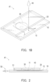
- FIG. 1B is an assembled view of the testing equipment of FIG. 1A
- the testing equipment with magnifying function A1 includes: a carrier 10 having a specimen holding area 11 formed on top, a cover 20 stacked on top of the carrier 10, and at least one magnifying part 30 rendering a convex lens type surface formed on the cover 20.
- the magnifying part 30 of the present example uses a planar convex lens as an example; however a dual sided lenticular or other type of magnifying lens may be adopted.
- the magnifying part 30 is disposed to correspond with the specimen holding area 11 of the carrier 10.
- the magnification of the magnifying part 30 may have different magnifications according to testing requirements of different tests.
- the magnifying part 30 and the cover 20 may be integrally formed, namely the magnifying part 30 and the cover 20 is a single component.
- the cover and the magnifying part may each be individual components that are adapted to be integrated together for conveniently integrating magnifying parts of different magnifications with the same cover.
- using the testing equipment A1 with magnifying function of the present example does not require a magnifying lens or microscope and such tools to be additionally arranged for achieving a purpose of testing.
- an additional step for alignment is also not necessary and is highly convenient.
- the specimen holding area 11 of the carrier 10 may specifically be formed with a depressed configuration.
- a more stable and larger storage space may be provided to a specimen 40 through the depressed configuration design, addressing the requirement where certain specimens are required to rest for a period of time before testing is performed. For example, before it is desired to perform the aforementioned motility testing on semen, it is necessary to be rested in room temperature for a period of time before testing is performed. Under these circumstances, the specimen 40 may be first instilled in the depressed configuration design specimen holding area 11 of the carrier 10 to rest for a period of time. As shown in FIG. 1B , an area of the cover 20 may be smaller than an area of the carrier 10.
- a specimen instillation port 12 exposed outside the cover 20 is formed on one side of the specimen holding area 11, and an air channel 13 extending beyond the other side of the cover 20 is selectively formed on the other side of the specimen holding area 11.
- the air channel 13 may prevent air filling the inside of the specimen holding area 11 causing instillation unable to be performed when the specimen is a fluid.
- the specimen instillation port 12 of the present embodiment is designed to have a shape expanding outwards, which may lower the possibility of the specimen unable to be smoothly instilled.
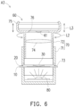
- FIG. 2 is a cross-sectional view of the testing equipment of FIG. 1A .
- a lateral illumination device 50 may be selectively disposed at one side of the carrier. Mainly, the brightness of the specimen 40 in the specimen holding area 11 may be increased by the addition of the lateral illumination device 50 to obtain better testing resolution.
- FIG. 3 is a flow diagram of testing for a testing equipment according to an example not forming part of the present invention.
- the testing equipment A1 with magnifying function shown in FIG. 1B for performing testing, first the specimen 40 desired to be tested is set in the specimen holding area 11 (labelled in FIG. 1A ), this is step S110 shown in FIG. 3 .
- the cover 20 may first be stacked on top the carrier 10, before setting the specimen 40 desired to be tested in the specimen holding area 11 from the specimen instillation port 12.
- the specimen 40 desired to be tested may be set in the specimen holding area 11 directly first, and then stacking the cover 20 on top the carrier 10.
- step S120 the specimen 40 is rested in the specimen holding area 11 selectively for a period of time according to testing requirements of the specimen 40, this is step S120 shown in FIG. 3 .
- a cell phone is attached on the cover 20, and the camera of the cell phone is aligned with the magnifying part 30, to conveniently use the camera of the cell phone to capture a picture or video of the specimen through the magnifying part 30, this is step S130 shown in FIG. 3 .
- an application (APP) installed in the cell phone or other analysis device may be used to perform analysis of the picture or video, for obtain testing results, this is step S140 shown in FIG. 3 .
- APP application
- FIG. 4 is a cross-sectional view of a testing equipment with magnifying function according to another example not forming part of the present invention.
- a protruding part 14 may further be formed on a top of the cover 20 of a testing equipment A2 at a periphery of the magnifying part 30.
- a protruding type support structure may be formed on top of the cover 20 by the addition of the protruding part 14.
- a side of the intelligent communications device 60 having a camera 61 disposed may be abutted on the protruding part 14 (along the direction shown by the arrow L1), to achieve a stable supporting function and effect.
- the testing equipment A2 of the present example may allow the user to arrange the intelligent communications device 60 for performing testing, and does not require an expensive testing apparatus for obtaining testing records of pictures and even recordings. Furthermore, regarding the design dimensions of the protruding part 14, considerations regarding the best observation distance for the user may be made in advance, enhancing the ease of use.
- FIG. 5 is a cross-sectional view of a testing equipment with magnifying function according to another example not forming part of the present invention.
- a testing equipment A3 of the present example may include a barrel type base 70.
- the barrel type base 70 includes a lower barrel base 71 and a liftable-descendable upper barrel body 72.
- the lower barrel base 71 has a lateral insertion port 73 providing an insert position for the cover 20 and the carrier 10 in a stacked state.
- An upward lighting device 80 is disposed on a bottom part of the lower barrel base 71, to address the space below the cover 20 and the carrier 10. That is to say, lighting may be provided to the cover 20 and the carrier 10.
- At least one magnification lens 74 is disposed in the upper barrel body 72.
- the upper barrel body 72 is rendered in a screw configuration with respect to the lower barrel base 71 and may be lifted and descended like a screw. Namely, the upper barrel body 72 is rotated with respect to the lower barrel base 71 along the arrow L2 directions for the upper barrel body 72 to move along the arrow L3 directions with respect to the lower barrel base 71, to adjust the height position of the magnification lens 74, further achieving an objective of adjusting the magnification.
- An assembling frame 75 may be disposed at an upper end of the upper barrel body 72.
- the assembling frame 75 may provide the existing intelligent communications device 60 with assembly positioning.
- the assembling frame 75 has a camera alignment hole 76.
- the camera alignment hole 76 is provided to be used to correspond with the camera 61 of the intelligent communications device 60.
- the testing equipment A3 disclosed in the present example may achieve a more complete and better to use magnifying testing function.
- the camera 61 disposed on current intelligent communications device 60 typically only have a digital zoom function. If higher accuracy testing is performed, generally an optical zoom lens is additionally required. However, the user using an arrangement of the testing equipment A3 and the intelligent communications device 60 of the present example, does not require an optical zoom lens to be additionally prepared, and furthermore the trouble of perfectly aligning the three, the intelligent communications device 60, the optical zoom lens and the specimen is saved. Furthermore, by arranging with the original digital zoom function of the camera 61, even more accurate testing may be performed.
- FIG. 6 shows the intelligent communications device 60 in a state already assembled and positioned on the assembling frame 75 which is disposed on the upper barrel body 72.
- Housed is the specimen 40, and the cover 20 and the carrier 10 in a stacked state are at the insert position in the lateral insertion port 73.
- the upward lighting device 80 may increase the brightness of the specimen.
- the upper barrel body 72 or the barrel type base 70 is rotated as shown in arrow L2 of FIG. 6 , to liftably-descendably adjust the height position of the magnification lens 74 along the direction indicated by the arrow L3 of FIG. 6 .
- the user may capture dynamic or static testing images of the specimen 40 after magnification through the camera 61 disposed on the intelligent communications device 60.
- the originally equipped functions of the intelligent communications device 60 may be used directly to perform storage and transferring of the testing images and such subsequent processes.
- FIG. 7 is a schematic diagram of a testing equipment with magnifying function according to another example not forming part of the present invention.
- a testing equipment A4 with magnifying function includes a plurality of magnifying parts 30, 30B, 30C of different magnifications disposed in intervals on the cover 20. The user may shift the cover 20 to align the specimen holding area 11 of the carrier 10 with any of the magnifying parts 30, 30B, 30C of different magnifications, conveniently obtaining testing results with different magnifications.
- the testing equipment A4 with magnifying function of a single module may satisfy the different needs of the user, saving the trouble of changing the magnifying part.
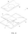
- FIG. 8 is a schematic diagram of a testing equipment with magnifying function according to another example not forming part of the present invention.
- a testing equipment A5 with magnifying function of the present invention further includes a flexible transparent film 15.
- the flexible transparent film 15 is disposed between the carrier 10 and the magnifying part 30, and is covered on the specimen holding area 11.
- the flexible transparent film 15 covers the specimen 40 (liquid) such that it tends to be in a confined steady state, such that outside air, dust and dirt interference factors are kept to the lowest.
- the testing equipment A5 may adjust the focal length by the thickness of the flexible transparent film 15.
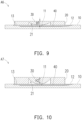
- FIG. 9 is a schematic diagram of a testing equipment with magnifying function according to another example not forming part of the present invention.
- the magnifying part 30 of a testing equipment A6 with magnifying function is a planar convex lens, and a surface of the magnifying part 30 facing the carrier 10 is a protruding surface. Therefore, an upwardly concave type hollow part 21 is formed at the surface of the magnifying part 30 facing the carrier 10.
- a focal length parameter H1 is defined by the thickness of the thickest part of the magnifying part 30 of the planar convex lens.
- FIG. 10 is a schematic diagram of a testing equipment with magnifying function according to another example not forming part of the present invention. As shown in FIG. 10 , a focal length parameter H2 of a testing equipment A7 with magnifying function is different than the focal length parameter H1 of FIG. 9 .
- the focal lengths H1 and H2 may change by the change in thickness of the cover 20 or the size of the curvature of the magnifying part 30 or differences in the change of thickness.
- the focal length H2 as shown in FIG. 10 is greater than the focal length H1 shown in FIG. 9 , and is achieved by changing the size of the curvature of the magnifying part 30. In this way, testing requirements with different focal lengths may be satisfied through the changing of different magnifying parts 30.
- the magnifying part 30 may be the only part rendered a transparent state and the cover 20 is a matte state.
- the carrier 10 may have only the specimen holding area 11 rendered in a transparent state, and the remaining parts then may be a matte state. In this way, when the testing operations are performed on the testing equipment, the translucent bright area may be concentrated at the specimen holding area 11, the magnifying part 30 and such main observation parts, lowering the light beam interference phenomenon from other parts.
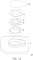
- FIG. 11 , FIG. 12 and FIG. 13 are exploded views of testing equipments with magnifying function according to three embodiments of the invention.
- the carrier 10 of the testing equipment A8 further has a light beam auxiliary guiding structure 16 formed at the bottom surface of the carrier 10.
- a material of the carrier 10 is made from transparent or translucent material.
- the light beam auxiliary guiding structure 16 is an engraved pattern that scatters the arriving light beam, and the light beam auxiliary guiding structure 16 may be an entire surface or constitute a particular pattern.
- the light beam auxiliary guiding structure 16 may also be formed all around the side surfaces of the carrier 10.
- the magnifying part 30 corresponds with the camera 61 of the intelligent communications device 60.
- a fill light (not shown) is disposed near the camera 61 on parts of the intelligent communications device 60.
- the light beam provided by the fill light may be guided in the carrier 10 to illuminate the specimen holding area 11 through the cover 20.
- the light beam auxiliary guiding structure 16 of the carrier 10 may cause the light beam provided by the fill light to scatter, further increasing the brightness of the specimen holding area 11.
- the cover 20 correspondingly covers the fill light of the intelligent communications device 60 as an example. Therefore, a light transmissible material is required to be adopted for the cover 20. However, the cover 20 may also not cover the fill light, in which the light beam provided by the fill light directly illuminates the carrier 10.
- the testing equipment A8 with magnifying function of the present embodiment may selectively include a non-slip film 92, a release paper 96 and a pH test paper 94.
- the non slip film 92 is attached on the top of the cover 20, and is used to stably position the cover 20 to the camera 61 of the intelligent communications device 60, as shown in FIG. 4 , such that the magnifying part 30 corresponds with the camera 61 of the intelligent communications device 60, composing the positioning of the intelligent communications device 60 on the testing equipment A8 and making the positioning state of the intelligent communications device 60 with the testing equipment A8 better through the disposition of the non slip film 92.
- the non slip film 92 of the present embodiment has an opening corresponding to the magnifying part 30, to prevent interference with the user observing the specimen through the magnifying part 30; however it should not be construed as a limitation to the invention.
- a material of the main body of the non slip film 92 for example, is silicon. Due to disposing the non slip film 92, the release paper 96 may be used to protect the surface of the non slip film 92, to maintain adhesion.
- the pH test paper 94 may be disposed on the specimen holding area 11 of the carrier 10, to provide a function for measuring the pH value of the specimen. Of course, the pH test paper 94 may be replaced after use.
- the magnifying part 30 and the cover 20 in the present embodiment adopts a separable type design. Therefore, the user may select a magnifying part 31 different from the magnifying part 30 to replace the original magnifying part 30 according to testing requirements.
- the magnifying part 31 and the cover 20 are assembled to obtain different magnifications or other optical features.
- a testing equipment A9 with magnifying function of the present embodiment further includes a specimen collection sheet 42 disposed in the specimen holding area 11.
- the specimen collection sheet 42 for example, has a specimen collection area 42A, using adhesion or other methods to collect subcutaneous tissue/cells, parasite eggs and the like solid test bodies.
- a testing equipment A10 with magnifying function further includes an isolation component 98 disposed at the specimen holding area 11 between the carrier 10 and the cover 20.
- the isolation component 98 may isolate the magnifying part 30 and the testing fluid in the specimen holding area 11, preventing the testing fluid contaminating the magnifying part 30.
- the testing equipment with magnifying function of the invention makes the conventional structures mentioned in the "Prior Art" of the invention capable of providing a simple structure significantly lowering the cost of the simple specimen magnifying testing structure, and further satisfying requirements for achieving diverse usages, mainly through the carrier having the specimen holding area, the magnifying part and such unique innovative type structures and technical features. Furthermore, it may be conveniently integrated with existing intelligent communications device, and enables the use of existing intelligent communications device to capture magnified testing images and perform subsequent operations such as storing and transferring, achieving improvements for more complete and better to use testing functions.
- the testing equipment does not require an additional light source to illuminate the carrier, achieving an objective of illuminating the specimen, further enhancing testing results.
- the testing equipment with magnifying function has the feature of low cost, and therefore may achieve an objective of disposable use.
- the testing equipment with magnifying function of the invention may be reused.
Landscapes
- Physics & Mathematics (AREA)
- Chemical & Material Sciences (AREA)
- Analytical Chemistry (AREA)
- Health & Medical Sciences (AREA)
- General Physics & Mathematics (AREA)
- General Health & Medical Sciences (AREA)
- Optics & Photonics (AREA)
- Life Sciences & Earth Sciences (AREA)
- Biochemistry (AREA)
- Immunology (AREA)
- Pathology (AREA)
- Hematology (AREA)
- Clinical Laboratory Science (AREA)
- Chemical Kinetics & Catalysis (AREA)
- Investigating Or Analysing Materials By Optical Means (AREA)
- Microscoopes, Condenser (AREA)
- Sampling And Sample Adjustment (AREA)
Description
- The invention relates to a testing equipment, and relates particularly to a testing equipment with a magnifying function.
- Currently, testing of fluid state contents, are typically consigned to professional testing authorities for performing testing by high magnification, expensive microscope equipment. In the situation where an individual does not have microscope equipment, the testing activity cannot be performed by the individual.
- However, in some testing categories nowadays testing is required to be performed on a regular basis; therefore generally for an individual it creates an excessive burden that consumes large amounts of time and money. For example, currently some medical procedures in the long term testing category are directed at infertility patients and include semen testing. This testing category is mainly directed at performing observations on the number of sperms and their motility. The method thereof mainly involves resting semen of a male subject at room temperature for a period of time, and taking a drop and instilling to a slide and setting under a microscope to perform observations for a period of time. The observations not only may be directed at performing high magnification observation of individual sperm to understand the external appearance of individual sperm, but may also be directed at performing observations of overall sperms in a group range, and their motility and the quantity per unit area. However, the reason why an individual is unable to perform testing is due to the reason that current related industries have not yet developed a testing product and the technology that conveniently allows an individual to perform testing through a simple aiding device. This problem is an important technical issue worthy to be considered and solved by related industries.
- Of course, the testing category aforementioned is only one specific problem desired to be solved by the invention. Observational needs such as for medical specimens or motility of water micro-organisms, water quality, skin epidermis tissues/cells and which other individual want to understand, also necessitates the need for developing a simple testing product with significantly lower cost of use than current microscope equipment.
-
- Directed at the aforementioned problems in conventional testing technology of specimen, how to develop a more ideal and practical innovative structure is a goal and a direction in which related industries need a breakthrough.
- In view of this, the inventor's many years of experience of engagement in the manufacturing, development and design directed at the aforementioned goal, after detailed design and careful assessment has finally achieved a practical invention.
- The invention provides a testing equipment with magnifying function, which solves a problem of past testing equipment being expensive, consuming high labor and not easy to popularize.
- The invention provides a testing equipment with magnifying function as set out in independent claim 1.
- In an embodiment of the invention, a lateral illumination device is disposed on a side of the carrier.
- According to the invention, the carrier is made from a transparent or translucent material and at least a bottom or all around thereof has an engraved pattern, such that a light beam from an outside environment is at least able to be reflected by the engraved pattern of the bottom of the carrier, so the light beam is guided throughout the carrier, making the specimen holding area of the carrier have sufficient light to illuminate a specimen.
- In one example, which does not form part of the present invention, a number of the magnifying part is a plurality, disposed in intervals at the cover and with a magnification different to each other.
- According to the invention, the cover and the magnifying part are rendered in a separable state, to provide the magnifying part with different magnification.
- In a further example, which does not form part of the present invention, the magnifying part and the cover are integrally formed.
- A testing equipment with magnifying function, not forming part of the present invention, comprises: a carrier, having at least one specimen holding area on top, and having a light beam auxiliary guiding structure, wherein the light beam auxiliary guiding structure guides a light beam of an outside environment to the specimen holding area of the carrier; a cover, at least stacked on the specimen holding area of the carrier, and the cover having a supporting side for an intelligent communications device; and at least one magnifying part, disposed at the cover, the magnifying part is disposed to align with the specimen holding area of the carrier.
- In an embodiment of the invention, a material of the carrier is made from a transparent or translucent material and at least a bottom or all around thereof has an engraved pattern, such that a light beam from an outside environment is at least able to be reflected by the engraved pattern of the bottom of the carrier, so the light beam is guided throughout the carrier, making the specimen holding area of the carrier have sufficient light to illuminate a specimen.
- In an embodiment of the invention, the testing equipment with magnifying function includes a non slip film, attached on top the cover, used to attach the cover to a camera of the intelligent communications device, so the magnifying part corresponds to the camera of the intelligent communications device.
- Based on the above, the invention provides a simple structure for a testing equipment with a magnifying function in which the cost is significantly lowered, and is suitable for performing simple specimen magnification testing and is not only practical but has improvements.
- Reference will now be made in detail to the present preferred embodiments of the invention, examples of which are illustrated in the accompanying drawings.
-
-
FIG. 1A is an exploded view of a testing equipment with magnifying function according to an example not forming part of the present invention. -
FIG. 1B is an assembled view of the testing equipment ofFIG. 1A . -
FIG. 2 is a cross-sectional view of the testing equipment ofFIG. 1A . -
FIG. 3 is a flow diagram of testing for a testing equipment according to an example not forming part of the present invention. -
FIG. 4 is a cross-sectional view of a testing equipment with magnifying function according to another example not forming part of the present invention. -
FIG. 5 is a cross-sectional view of a testing equipment with magnifying function according to another example not forming part of the present invention. -
FIG. 6 is a schematic diagram of the testing equipment ofFIG. 5 in a usage state. -
FIG. 7 is a schematic diagram of a testing equipment with magnifying function according to another example not forming part of the present invention. -
FIG. 8 is a schematic diagram of a testing equipment with magnifying function according to another example not forming part of the present invention. -
FIG. 9 is a schematic diagram of a testing equipment with magnifying function according to another example not forming part of the present invention. -
FIG. 10 is a schematic diagram of a testing equipment with magnifying function according to another example not forming part of the present invention. -
FIG. 11 ,FIG. 12 andFIG. 13 are exploded views of testing equipments with magnifying function according to three embodiments of the invention. - Reference number list:
- A1-A10: testing equipment with magnifying function;
- 10: carrier;
- 11: specimen holding area;
- 12: specimen instillation port;
- 13: air channel;
- 20: cover;
- 30, 30B, 30C, 31: magnifying part;
- 40: specimen;
- 50: lateral illumination device;
- 60: intelligent communications device;
- 61: camera;
- L1 ' L2 ' L3: arrow;
- 14: protruding part;
- 70: barrel type base;
- 71: lower barrel base;
- 72: upper barrel body;
- 73: lateral insertion port;
- 74: magnification lens;
- 75: assembling frame;
- 76: camera alignment hole;
- 80: upward lighting device;
- 15: flexible transparent film;
- H1, H2: focal length parameter;
- 16: light beam auxiliary guiding structure;
- 92: non-slip film;
- 94: pH test paper;
- 96: release paper;
- 98: isolation component;
- 42: specimen collection sheet;
- 42A: specimen collection area.
-
FIG. 1A is an exploded view of a testing equipment with magnifying function according to an example, not forming part of the present invention, andFIG. 1B is an assembled view of the testing equipment ofFIG. 1A . The testing equipment with magnifying function A1 includes: acarrier 10 having aspecimen holding area 11 formed on top, acover 20 stacked on top of thecarrier 10, and at least one magnifyingpart 30 rendering a convex lens type surface formed on thecover 20. The magnifyingpart 30 of the present example uses a planar convex lens as an example; however a dual sided lenticular or other type of magnifying lens may be adopted. The magnifyingpart 30 is disposed to correspond with thespecimen holding area 11 of thecarrier 10. The magnification of the magnifyingpart 30 may have different magnifications according to testing requirements of different tests. The magnifyingpart 30 and thecover 20 may be integrally formed, namely the magnifyingpart 30 and thecover 20 is a single component. In other embodiments, the cover and the magnifying part may each be individual components that are adapted to be integrated together for conveniently integrating magnifying parts of different magnifications with the same cover. In other words, using the testing equipment A1 with magnifying function of the present example does not require a magnifying lens or microscope and such tools to be additionally arranged for achieving a purpose of testing. Furthermore, an additional step for alignment is also not necessary and is highly convenient. - As shown in
FIG. 1A , thespecimen holding area 11 of thecarrier 10 may specifically be formed with a depressed configuration. A more stable and larger storage space may be provided to aspecimen 40 through the depressed configuration design, addressing the requirement where certain specimens are required to rest for a period of time before testing is performed. For example, before it is desired to perform the aforementioned motility testing on semen, it is necessary to be rested in room temperature for a period of time before testing is performed. Under these circumstances, thespecimen 40 may be first instilled in the depressed configuration designspecimen holding area 11 of thecarrier 10 to rest for a period of time. As shown inFIG. 1B , an area of thecover 20 may be smaller than an area of thecarrier 10. Aspecimen instillation port 12 exposed outside thecover 20 is formed on one side of thespecimen holding area 11, and anair channel 13 extending beyond the other side of thecover 20 is selectively formed on the other side of thespecimen holding area 11. Theair channel 13 may prevent air filling the inside of thespecimen holding area 11 causing instillation unable to be performed when the specimen is a fluid. In addition, thespecimen instillation port 12 of the present embodiment is designed to have a shape expanding outwards, which may lower the possibility of the specimen unable to be smoothly instilled. -
FIG. 2 is a cross-sectional view of the testing equipment ofFIG. 1A . As shown inFIG. 2 , alateral illumination device 50 may be selectively disposed at one side of the carrier. Mainly, the brightness of thespecimen 40 in thespecimen holding area 11 may be increased by the addition of thelateral illumination device 50 to obtain better testing resolution. -
FIG. 3 is a flow diagram of testing for a testing equipment according to an example not forming part of the present invention. When using the testing equipment A1 with magnifying function shown inFIG. 1B for performing testing, first thespecimen 40 desired to be tested is set in the specimen holding area 11 (labelled inFIG. 1A ), this is step S110 shown inFIG. 3 . In step S110, thecover 20 may first be stacked on top thecarrier 10, before setting thespecimen 40 desired to be tested in thespecimen holding area 11 from thespecimen instillation port 12. Of course, thespecimen 40 desired to be tested may be set in thespecimen holding area 11 directly first, and then stacking thecover 20 on top thecarrier 10. Next, thespecimen 40 is rested in thespecimen holding area 11 selectively for a period of time according to testing requirements of thespecimen 40, this is step S120 shown inFIG. 3 . Later, a cell phone is attached on thecover 20, and the camera of the cell phone is aligned with the magnifyingpart 30, to conveniently use the camera of the cell phone to capture a picture or video of the specimen through the magnifyingpart 30, this is step S130 shown inFIG. 3 . Lastly, an application (APP) installed in the cell phone or other analysis device may be used to perform analysis of the picture or video, for obtain testing results, this is step S140 shown inFIG. 3 . -
FIG. 4 is a cross-sectional view of a testing equipment with magnifying function according to another example not forming part of the present invention. As shown inFIG. 4 , a protrudingpart 14 may further be formed on a top of thecover 20 of a testing equipment A2 at a periphery of the magnifyingpart 30. In the example, a protruding type support structure may be formed on top of thecover 20 by the addition of the protrudingpart 14. When the user desires to adopt an existingintelligent communications device 60 to perform testing, a side of theintelligent communications device 60 having acamera 61 disposed may be abutted on the protruding part 14 (along the direction shown by the arrow L1), to achieve a stable supporting function and effect. In this way, the testing equipment A2 of the present example may allow the user to arrange theintelligent communications device 60 for performing testing, and does not require an expensive testing apparatus for obtaining testing records of pictures and even recordings. Furthermore, regarding the design dimensions of the protrudingpart 14, considerations regarding the best observation distance for the user may be made in advance, enhancing the ease of use. -
FIG. 5 is a cross-sectional view of a testing equipment with magnifying function according to another example not forming part of the present invention. As shown inFIG. 5 andFIG. 6 , a testing equipment A3 of the present example may include abarrel type base 70. Thebarrel type base 70 includes alower barrel base 71 and a liftable-descendableupper barrel body 72. Thelower barrel base 71 has alateral insertion port 73 providing an insert position for thecover 20 and thecarrier 10 in a stacked state. Anupward lighting device 80 is disposed on a bottom part of thelower barrel base 71, to address the space below thecover 20 and thecarrier 10. That is to say, lighting may be provided to thecover 20 and thecarrier 10. At least onemagnification lens 74 is disposed in theupper barrel body 72. Theupper barrel body 72 is rendered in a screw configuration with respect to thelower barrel base 71 and may be lifted and descended like a screw. Namely, theupper barrel body 72 is rotated with respect to thelower barrel base 71 along the arrow L2 directions for theupper barrel body 72 to move along the arrow L3 directions with respect to thelower barrel base 71, to adjust the height position of themagnification lens 74, further achieving an objective of adjusting the magnification. An assemblingframe 75 may be disposed at an upper end of theupper barrel body 72. The assemblingframe 75 may provide the existingintelligent communications device 60 with assembly positioning. The assemblingframe 75 has acamera alignment hole 76. Thecamera alignment hole 76 is provided to be used to correspond with thecamera 61 of theintelligent communications device 60. The testing equipment A3 disclosed in the present example may achieve a more complete and better to use magnifying testing function. - The
camera 61 disposed on currentintelligent communications device 60 typically only have a digital zoom function. If higher accuracy testing is performed, generally an optical zoom lens is additionally required. However, the user using an arrangement of the testing equipment A3 and theintelligent communications device 60 of the present example, does not require an optical zoom lens to be additionally prepared, and furthermore the trouble of perfectly aligning the three, theintelligent communications device 60, the optical zoom lens and the specimen is saved. Furthermore, by arranging with the original digital zoom function of thecamera 61, even more accurate testing may be performed. -
FIG. 6 shows theintelligent communications device 60 in a state already assembled and positioned on the assemblingframe 75 which is disposed on theupper barrel body 72. Housed is thespecimen 40, and thecover 20 and thecarrier 10 in a stacked state are at the insert position in thelateral insertion port 73. Theupward lighting device 80 may increase the brightness of the specimen. Then, theupper barrel body 72 or thebarrel type base 70 is rotated as shown in arrow L2 ofFIG. 6 , to liftably-descendably adjust the height position of themagnification lens 74 along the direction indicated by the arrow L3 ofFIG. 6 . In this way, a function of adjusting the magnification may be achieved. The user may capture dynamic or static testing images of thespecimen 40 after magnification through thecamera 61 disposed on theintelligent communications device 60. Furthermore, the originally equipped functions of theintelligent communications device 60 may be used directly to perform storage and transferring of the testing images and such subsequent processes. -
FIG. 7 is a schematic diagram of a testing equipment with magnifying function according to another example not forming part of the present invention. As shown inFIG. 7 , a testing equipment A4 with magnifying function includes a plurality of magnifyingparts cover 20. The user may shift thecover 20 to align thespecimen holding area 11 of thecarrier 10 with any of the magnifyingparts -
FIG. 8 is a schematic diagram of a testing equipment with magnifying function according to another example not forming part of the present invention. As shown inFIG. 8 , a testing equipment A5 with magnifying function of the present invention further includes a flexibletransparent film 15. The flexibletransparent film 15 is disposed between thecarrier 10 and the magnifyingpart 30, and is covered on thespecimen holding area 11. The flexibletransparent film 15 covers the specimen 40 (liquid) such that it tends to be in a confined steady state, such that outside air, dust and dirt interference factors are kept to the lowest. Furthermore, the testing equipment A5 may adjust the focal length by the thickness of the flexibletransparent film 15. -
FIG. 9 is a schematic diagram of a testing equipment with magnifying function according to another example not forming part of the present invention. As shown inFIG. 9 , the magnifyingpart 30 of a testing equipment A6 with magnifying function is a planar convex lens, and a surface of the magnifyingpart 30 facing thecarrier 10 is a protruding surface. Therefore, an upwardly concave typehollow part 21 is formed at the surface of the magnifyingpart 30 facing thecarrier 10. A focal length parameter H1 is defined by the thickness of the thickest part of the magnifyingpart 30 of the planar convex lens.FIG. 10 is a schematic diagram of a testing equipment with magnifying function according to another example not forming part of the present invention. As shown inFIG. 10 , a focal length parameter H2 of a testing equipment A7 with magnifying function is different than the focal length parameter H1 ofFIG. 9 . - The focal lengths H1 and H2 may change by the change in thickness of the
cover 20 or the size of the curvature of the magnifyingpart 30 or differences in the change of thickness. The focal length H2 as shown inFIG. 10 is greater than the focal length H1 shown inFIG. 9 , and is achieved by changing the size of the curvature of the magnifyingpart 30. In this way, testing requirements with different focal lengths may be satisfied through the changing of differentmagnifying parts 30. - The magnifying
part 30 may be the only part rendered a transparent state and thecover 20 is a matte state. In addition, thecarrier 10 may have only thespecimen holding area 11 rendered in a transparent state, and the remaining parts then may be a matte state. In this way, when the testing operations are performed on the testing equipment, the translucent bright area may be concentrated at thespecimen holding area 11, the magnifyingpart 30 and such main observation parts, lowering the light beam interference phenomenon from other parts. -
FIG. 11 ,FIG. 12 andFIG. 13 are exploded views of testing equipments with magnifying function according to three embodiments of the invention. Next referring toFIG. 11 , in a testing equipment A8 with magnifying function of the present embodiment, thecarrier 10 of the testing equipment A8 further has a light beamauxiliary guiding structure 16 formed at the bottom surface of thecarrier 10. A material of thecarrier 10 is made from transparent or translucent material. According to the invention, the light beamauxiliary guiding structure 16 is an engraved pattern that scatters the arriving light beam, and the light beamauxiliary guiding structure 16 may be an entire surface or constitute a particular pattern. Of course, the light beamauxiliary guiding structure 16 may also be formed all around the side surfaces of thecarrier 10. When thecover 20 and thecarrier 10 in a stacked state are attached to the intelligent communications device 60 (refer toFIG. 4 ), the magnifyingpart 30 corresponds with thecamera 61 of theintelligent communications device 60. In addition, a fill light (not shown) is disposed near thecamera 61 on parts of theintelligent communications device 60. The light beam provided by the fill light may be guided in thecarrier 10 to illuminate thespecimen holding area 11 through thecover 20. At the same time, the light beamauxiliary guiding structure 16 of thecarrier 10 may cause the light beam provided by the fill light to scatter, further increasing the brightness of thespecimen holding area 11. By disposing the light beamauxiliary guiding structure 16, the testing equipment does not require an additional fill light source to illuminate thecarrier 10, achieving an objective of illuminating the specimen. In the present embodiment, thecover 20 correspondingly covers the fill light of theintelligent communications device 60 as an example. Therefore, a light transmissible material is required to be adopted for thecover 20. However, thecover 20 may also not cover the fill light, in which the light beam provided by the fill light directly illuminates thecarrier 10. - The testing equipment A8 with magnifying function of the present embodiment may selectively include a
non-slip film 92, arelease paper 96 and apH test paper 94. Thenon slip film 92 is attached on the top of thecover 20, and is used to stably position thecover 20 to thecamera 61 of theintelligent communications device 60, as shown inFIG. 4 , such that the magnifyingpart 30 corresponds with thecamera 61 of theintelligent communications device 60, composing the positioning of theintelligent communications device 60 on the testing equipment A8 and making the positioning state of theintelligent communications device 60 with the testing equipment A8 better through the disposition of thenon slip film 92. Thenon slip film 92 of the present embodiment has an opening corresponding to the magnifyingpart 30, to prevent interference with the user observing the specimen through the magnifyingpart 30; however it should not be construed as a limitation to the invention. A material of the main body of thenon slip film 92, for example, is silicon. Due to disposing thenon slip film 92, therelease paper 96 may be used to protect the surface of thenon slip film 92, to maintain adhesion. In addition, thepH test paper 94 may be disposed on thespecimen holding area 11 of thecarrier 10, to provide a function for measuring the pH value of the specimen. Of course, thepH test paper 94 may be replaced after use. - In addition, the magnifying
part 30 and thecover 20 in the present embodiment adopts a separable type design. Therefore, the user may select a magnifyingpart 31 different from the magnifyingpart 30 to replace the original magnifyingpart 30 according to testing requirements. The magnifyingpart 31 and thecover 20 are assembled to obtain different magnifications or other optical features. - Next, referring to
FIG. 12 , a testing equipment A9 with magnifying function of the present embodiment further includes aspecimen collection sheet 42 disposed in thespecimen holding area 11. Thespecimen collection sheet 42, for example, has aspecimen collection area 42A, using adhesion or other methods to collect subcutaneous tissue/cells, parasite eggs and the like solid test bodies. - Next, referring to
FIG. 13 , a testing equipment A10 with magnifying function further includes anisolation component 98 disposed at thespecimen holding area 11 between thecarrier 10 and thecover 20. Theisolation component 98 may isolate the magnifyingpart 30 and the testing fluid in thespecimen holding area 11, preventing the testing fluid contaminating the magnifyingpart 30. - In summary, the testing equipment with magnifying function of the invention makes the conventional structures mentioned in the "Prior Art" of the invention capable of providing a simple structure significantly lowering the cost of the simple specimen magnifying testing structure, and further satisfying requirements for achieving diverse usages, mainly through the carrier having the specimen holding area, the magnifying part and such unique innovative type structures and technical features. Furthermore, it may be conveniently integrated with existing intelligent communications device, and enables the use of existing intelligent communications device to capture magnified testing images and perform subsequent operations such as storing and transferring, achieving improvements for more complete and better to use testing functions.
- On the other hand, by disposing of the light beam auxiliary guiding structure the testing equipment does not require an additional light source to illuminate the carrier, achieving an objective of illuminating the specimen, further enhancing testing results. At the same time the testing equipment with magnifying function has the feature of low cost, and therefore may achieve an objective of disposable use. Of course, the testing equipment with magnifying function of the invention may be reused.
Claims (4)
- A testing equipment with magnifying function, comprising:a carrier (10) made of a transparent or translucent material, the carrier having a specimen holding area (11) and an engraved pattern (16);a stacked cover (20) detachably stacked on the carrier, wherein the stacked cover (20) is made of a light transmissible material;a magnifying part (30) assemblable to and separable from the stacked cover (20), wherein the magnifying part (30) is disposed to align with the specimen holding area (11) of the carrier (10); andthe specimen holding area (11) receiving illumination through the stacked cover (20) and the carrier (10), wherein the carrier (10) is configured to guide light beams through the transparent or translucent material, and wherein the engraved pattern (16) of the carrier (10) is configured to reflect the light beams to illuminate the specimen holding area (11).
- The testing equipment with magnifying function of claim 1, wherein the carrier (10) includes a specimen installation port (12) exposed outside the stacked cover (20) for retrieving a specimen onto the specimen holding area (11).
- The testing equipment with magnifying function of claim 1, further comprising:
a pH test component (94) disposed on the specimen holding area (11) for measuring pH value of a specimen. - The testing equipment with magnifying function as claimed in claim 1, further comprising:
a nonslip film (92) configured to attach the stacked cover to a camera of a communication device, so that the magnifying part corresponds to the camera of the communication device.
Applications Claiming Priority (2)
| Application Number | Priority Date | Filing Date | Title |
|---|---|---|---|
| CN201410652104.0A CN105675495A (en) | 2014-11-17 | 2014-11-17 | Detection device with amplification function |
| PCT/CN2015/091862 WO2016078489A1 (en) | 2014-11-17 | 2015-10-13 | Examination device having magnification function |
Publications (3)
| Publication Number | Publication Date |
|---|---|
| EP3222994A1 EP3222994A1 (en) | 2017-09-27 |
| EP3222994A4 EP3222994A4 (en) | 2018-03-21 |
| EP3222994B1 true EP3222994B1 (en) | 2024-03-20 |
Family
ID=56013262
Family Applications (1)
| Application Number | Title | Priority Date | Filing Date |
|---|---|---|---|
| EP15861680.5A Active EP3222994B1 (en) | 2014-11-17 | 2015-10-13 | Examination device having magnification function |
Country Status (5)
| Country | Link |
|---|---|
| EP (1) | EP3222994B1 (en) |
| CN (1) | CN105675495A (en) |
| DK (1) | DK3222994T3 (en) |
| ES (1) | ES2982104T3 (en) |
| WO (1) | WO2016078489A1 (en) |
Families Citing this family (3)
| Publication number | Priority date | Publication date | Assignee | Title |
|---|---|---|---|---|
| CN108169884B (en) * | 2018-02-26 | 2024-01-30 | 南京恒晓光电科技有限公司 | Portable optical microscope |
| FR3117896B1 (en) * | 2020-12-22 | 2026-04-17 | Imv Tech | Support for microscopic analysis of a liquid-based biological substance and a system comprising such a support and a microscope |
| CN116727020B (en) * | 2023-07-05 | 2025-10-31 | 皖南医学院 | Animal mesentery microcirculation living body observation bath |
Citations (3)
| Publication number | Priority date | Publication date | Assignee | Title |
|---|---|---|---|---|
| US2801568A (en) * | 1954-11-15 | 1957-08-06 | Evelyn S Dakin | Microscope slide |
| JPS5751911U (en) * | 1980-09-06 | 1982-03-25 | ||
| CN2269833Y (en) * | 1995-10-04 | 1997-12-10 | 陈贯 | Portable ovulatory period microscopic measurer |
Family Cites Families (9)
| Publication number | Priority date | Publication date | Assignee | Title |
|---|---|---|---|---|
| US2015949A (en) * | 1934-07-28 | 1935-10-01 | Maw Frank James | Slide for testing liquids |
| US20020048819A1 (en) * | 2000-10-24 | 2002-04-25 | Kenneth Alley | Test strip for use in an apparatus for sampling and testing a specimen |
| CN201535752U (en) * | 2009-11-13 | 2010-07-28 | 冯俊 | Portable detector |
| CN202083642U (en) * | 2011-05-12 | 2011-12-21 | 深圳市吉隆洁净技术有限公司 | Purple light amplification verification instrument |
| WO2013191665A2 (en) * | 2012-06-21 | 2013-12-27 | Grimed Saglik Hizmetleri Ve Bilgisayar Urunleri Sanayi Ticaret Limited Sirketi | A mobile microscopy device being able to take images in different wavelengths (multispectral) |
| CN202974876U (en) * | 2012-10-31 | 2013-06-05 | 厦门优迈科医学仪器有限公司 | Semen detecting device |
| JP6038341B2 (en) * | 2012-12-21 | 2016-12-07 | インテル・コーポレーション | Electronic computing device and lens apparatus |
| CN203232198U (en) * | 2013-05-16 | 2013-10-09 | 张生 | Glass slide with convenient use |
| CN203688559U (en) * | 2013-12-31 | 2014-07-02 | 中国科学院深圳先进技术研究院 | Medical detector |
-
2014
- 2014-11-17 CN CN201410652104.0A patent/CN105675495A/en active Pending
-
2015
- 2015-10-13 ES ES15861680T patent/ES2982104T3/en active Active
- 2015-10-13 EP EP15861680.5A patent/EP3222994B1/en active Active
- 2015-10-13 DK DK15861680.5T patent/DK3222994T3/en active
- 2015-10-13 WO PCT/CN2015/091862 patent/WO2016078489A1/en not_active Ceased
Patent Citations (3)
| Publication number | Priority date | Publication date | Assignee | Title |
|---|---|---|---|---|
| US2801568A (en) * | 1954-11-15 | 1957-08-06 | Evelyn S Dakin | Microscope slide |
| JPS5751911U (en) * | 1980-09-06 | 1982-03-25 | ||
| CN2269833Y (en) * | 1995-10-04 | 1997-12-10 | 陈贯 | Portable ovulatory period microscopic measurer |
Also Published As
| Publication number | Publication date |
|---|---|
| EP3222994A4 (en) | 2018-03-21 |
| DK3222994T3 (en) | 2024-04-15 |
| WO2016078489A1 (en) | 2016-05-26 |
| CN105675495A (en) | 2016-06-15 |
| ES2982104T3 (en) | 2024-10-14 |
| EP3222994A1 (en) | 2017-09-27 |
Similar Documents
| Publication | Publication Date | Title |
|---|---|---|
| US9664611B2 (en) | Testing equipment with magnifying function | |
| US10281386B2 (en) | Automated testing apparatus | |
| EP3244250B1 (en) | Testing equipment with dual cameras | |
| CN102576406B (en) | Compact automated cell counter | |
| US10324022B2 (en) | Analysis accuracy improvement in automated testing apparatus | |
| EP3872566A1 (en) | Portable micro imaging device | |
| CN104423026A (en) | Portable terminal adaptor for microscope, and microscopic imaging method using the portable terminal adaptor | |
| US20170330321A1 (en) | Testing equipment with magnifying function | |
| US10036881B2 (en) | Digital microscope system for a mobile device | |
| KR102516836B1 (en) | Sample analysis device compatible with mobile device and sample observing method using thereof | |
| EP3222994A1 (en) | Examination device having magnification function | |
| EP2841990B1 (en) | Phone camera and sample stand | |
| US9958658B2 (en) | Testing equipment with magnifying function | |
| CN110408513B (en) | Devices for testing biological samples and methods for determining the characteristics of biological samples | |
| WO2018087665A1 (en) | Portable upright bright field microscope with smart device compatibility | |
| CN109445087A (en) | A kind of portable microscope slide observation box, imaging device and method | |
| CN216133240U (en) | Body fluid detection microscope device | |
| US10775600B2 (en) | Smart media device platform as an inverse microscopic imaging apparatus | |
| US20190056642A1 (en) | Microscope ocular lens camera adaptor | |
| JP2001242384A (en) | Objective lens for microscope and microscope using the same | |
| KR20160147668A (en) | Lens attachment | |
| CN205562945U (en) | Micro - signal acquisition auxiliary device |
Legal Events
| Date | Code | Title | Description |
|---|---|---|---|
| STAA | Information on the status of an ep patent application or granted ep patent |
Free format text: STATUS: THE INTERNATIONAL PUBLICATION HAS BEEN MADE |
|
| PUAI | Public reference made under article 153(3) epc to a published international application that has entered the european phase |
Free format text: ORIGINAL CODE: 0009012 |
|
| STAA | Information on the status of an ep patent application or granted ep patent |
Free format text: STATUS: REQUEST FOR EXAMINATION WAS MADE |
|
| 17P | Request for examination filed |
Effective date: 20170619 |
|
| AK | Designated contracting states |
Kind code of ref document: A1 Designated state(s): AL AT BE BG CH CY CZ DE DK EE ES FI FR GB GR HR HU IE IS IT LI LT LU LV MC MK MT NL NO PL PT RO RS SE SI SK SM TR |
|
| AX | Request for extension of the european patent |
Extension state: BA ME |
|
| RIC1 | Information provided on ipc code assigned before grant |
Ipc: G02B 21/00 20060101ALI20171110BHEP Ipc: G01N 21/01 20060101AFI20171110BHEP Ipc: G01N 21/03 20060101ALI20171110BHEP |
|
| DAV | Request for validation of the european patent (deleted) | ||
| DAX | Request for extension of the european patent (deleted) | ||
| A4 | Supplementary search report drawn up and despatched |
Effective date: 20180221 |
|
| RIC1 | Information provided on ipc code assigned before grant |
Ipc: G01N 21/01 20060101AFI20180215BHEP Ipc: G01N 21/03 20060101ALI20180215BHEP Ipc: G02B 21/00 20060101ALI20180215BHEP |
|
| STAA | Information on the status of an ep patent application or granted ep patent |
Free format text: STATUS: EXAMINATION IS IN PROGRESS |
|
| 17Q | First examination report despatched |
Effective date: 20210820 |
|
| REG | Reference to a national code |
Ref country code: DE Ref legal event code: R079 Free format text: PREVIOUS MAIN CLASS: G01N0021010000 Ipc: B01L0003000000 Ref country code: DE Ref legal event code: R079 Ref document number: 602015088011 Country of ref document: DE Free format text: PREVIOUS MAIN CLASS: G01N0021010000 Ipc: B01L0003000000 |
|
| GRAP | Despatch of communication of intention to grant a patent |
Free format text: ORIGINAL CODE: EPIDOSNIGR1 |
|
| STAA | Information on the status of an ep patent application or granted ep patent |
Free format text: STATUS: GRANT OF PATENT IS INTENDED |
|
| RIC1 | Information provided on ipc code assigned before grant |
Ipc: G02B 21/34 20060101ALI20231113BHEP Ipc: G02B 21/00 20060101ALI20231113BHEP Ipc: G01N 21/03 20060101ALI20231113BHEP Ipc: B01L 3/00 20060101AFI20231113BHEP |
|
| INTG | Intention to grant announced |
Effective date: 20231127 |
|
| GRAS | Grant fee paid |
Free format text: ORIGINAL CODE: EPIDOSNIGR3 |
|
| GRAA | (expected) grant |
Free format text: ORIGINAL CODE: 0009210 |
|
| STAA | Information on the status of an ep patent application or granted ep patent |
Free format text: STATUS: THE PATENT HAS BEEN GRANTED |
|
| P01 | Opt-out of the competence of the unified patent court (upc) registered |
Effective date: 20240123 |
|
| AK | Designated contracting states |
Kind code of ref document: B1 Designated state(s): AL AT BE BG CH CY CZ DE DK EE ES FI FR GB GR HR HU IE IS IT LI LT LU LV MC MK MT NL NO PL PT RO RS SE SI SK SM TR |
|
| RAP3 | Party data changed (applicant data changed or rights of an application transferred) |
Owner name: BONRAYBIO CO. LTD. |
|
| REG | Reference to a national code |
Ref country code: GB Ref legal event code: FG4D |
|
| REG | Reference to a national code |
Ref country code: CH Ref legal event code: EP |
|
| REG | Reference to a national code |
Ref country code: DE Ref legal event code: R096 Ref document number: 602015088011 Country of ref document: DE |
|
| REG | Reference to a national code |
Ref country code: IE Ref legal event code: FG4D |
|
| REG | Reference to a national code |
Ref country code: DK Ref legal event code: T3 Effective date: 20240409 |
|
| PG25 | Lapsed in a contracting state [announced via postgrant information from national office to epo] |
Ref country code: LT Free format text: LAPSE BECAUSE OF FAILURE TO SUBMIT A TRANSLATION OF THE DESCRIPTION OR TO PAY THE FEE WITHIN THE PRESCRIBED TIME-LIMIT Effective date: 20240320 |
|
| REG | Reference to a national code |
Ref country code: LT Ref legal event code: MG9D |
|
| PG25 | Lapsed in a contracting state [announced via postgrant information from national office to epo] |
Ref country code: GR Free format text: LAPSE BECAUSE OF FAILURE TO SUBMIT A TRANSLATION OF THE DESCRIPTION OR TO PAY THE FEE WITHIN THE PRESCRIBED TIME-LIMIT Effective date: 20240621 |
|
| PG25 | Lapsed in a contracting state [announced via postgrant information from national office to epo] |
Ref country code: HR Free format text: LAPSE BECAUSE OF FAILURE TO SUBMIT A TRANSLATION OF THE DESCRIPTION OR TO PAY THE FEE WITHIN THE PRESCRIBED TIME-LIMIT Effective date: 20240320 Ref country code: RS Free format text: LAPSE BECAUSE OF FAILURE TO SUBMIT A TRANSLATION OF THE DESCRIPTION OR TO PAY THE FEE WITHIN THE PRESCRIBED TIME-LIMIT Effective date: 20240620 |
|
| REG | Reference to a national code |
Ref country code: NL Ref legal event code: MP Effective date: 20240320 |
|
| PG25 | Lapsed in a contracting state [announced via postgrant information from national office to epo] |
Ref country code: RS Free format text: LAPSE BECAUSE OF FAILURE TO SUBMIT A TRANSLATION OF THE DESCRIPTION OR TO PAY THE FEE WITHIN THE PRESCRIBED TIME-LIMIT Effective date: 20240620 Ref country code: NO Free format text: LAPSE BECAUSE OF FAILURE TO SUBMIT A TRANSLATION OF THE DESCRIPTION OR TO PAY THE FEE WITHIN THE PRESCRIBED TIME-LIMIT Effective date: 20240620 Ref country code: LT Free format text: LAPSE BECAUSE OF FAILURE TO SUBMIT A TRANSLATION OF THE DESCRIPTION OR TO PAY THE FEE WITHIN THE PRESCRIBED TIME-LIMIT Effective date: 20240320 Ref country code: HR Free format text: LAPSE BECAUSE OF FAILURE TO SUBMIT A TRANSLATION OF THE DESCRIPTION OR TO PAY THE FEE WITHIN THE PRESCRIBED TIME-LIMIT Effective date: 20240320 Ref country code: GR Free format text: LAPSE BECAUSE OF FAILURE TO SUBMIT A TRANSLATION OF THE DESCRIPTION OR TO PAY THE FEE WITHIN THE PRESCRIBED TIME-LIMIT Effective date: 20240621 Ref country code: FI Free format text: LAPSE BECAUSE OF FAILURE TO SUBMIT A TRANSLATION OF THE DESCRIPTION OR TO PAY THE FEE WITHIN THE PRESCRIBED TIME-LIMIT Effective date: 20240320 Ref country code: BG Free format text: LAPSE BECAUSE OF FAILURE TO SUBMIT A TRANSLATION OF THE DESCRIPTION OR TO PAY THE FEE WITHIN THE PRESCRIBED TIME-LIMIT Effective date: 20240320 |
|
| REG | Reference to a national code |
Ref country code: AT Ref legal event code: MK05 Ref document number: 1667367 Country of ref document: AT Kind code of ref document: T Effective date: 20240320 |
|
| PG25 | Lapsed in a contracting state [announced via postgrant information from national office to epo] |
Ref country code: SE Free format text: LAPSE BECAUSE OF FAILURE TO SUBMIT A TRANSLATION OF THE DESCRIPTION OR TO PAY THE FEE WITHIN THE PRESCRIBED TIME-LIMIT Effective date: 20240320 Ref country code: LV Free format text: LAPSE BECAUSE OF FAILURE TO SUBMIT A TRANSLATION OF THE DESCRIPTION OR TO PAY THE FEE WITHIN THE PRESCRIBED TIME-LIMIT Effective date: 20240320 |
|
| PG25 | Lapsed in a contracting state [announced via postgrant information from national office to epo] |
Ref country code: NL Free format text: LAPSE BECAUSE OF FAILURE TO SUBMIT A TRANSLATION OF THE DESCRIPTION OR TO PAY THE FEE WITHIN THE PRESCRIBED TIME-LIMIT Effective date: 20240320 |
|
| PG25 | Lapsed in a contracting state [announced via postgrant information from national office to epo] |
Ref country code: NL Free format text: LAPSE BECAUSE OF FAILURE TO SUBMIT A TRANSLATION OF THE DESCRIPTION OR TO PAY THE FEE WITHIN THE PRESCRIBED TIME-LIMIT Effective date: 20240320 |
|
| PG25 | Lapsed in a contracting state [announced via postgrant information from national office to epo] |
Ref country code: IS Free format text: LAPSE BECAUSE OF FAILURE TO SUBMIT A TRANSLATION OF THE DESCRIPTION OR TO PAY THE FEE WITHIN THE PRESCRIBED TIME-LIMIT Effective date: 20240720 |
|
| PG25 | Lapsed in a contracting state [announced via postgrant information from national office to epo] |
Ref country code: PT Free format text: LAPSE BECAUSE OF FAILURE TO SUBMIT A TRANSLATION OF THE DESCRIPTION OR TO PAY THE FEE WITHIN THE PRESCRIBED TIME-LIMIT Effective date: 20240722 Ref country code: SM Free format text: LAPSE BECAUSE OF FAILURE TO SUBMIT A TRANSLATION OF THE DESCRIPTION OR TO PAY THE FEE WITHIN THE PRESCRIBED TIME-LIMIT Effective date: 20240320 |
|
| REG | Reference to a national code |
Ref country code: ES Ref legal event code: FG2A Ref document number: 2982104 Country of ref document: ES Kind code of ref document: T3 Effective date: 20241014 |
|
| PG25 | Lapsed in a contracting state [announced via postgrant information from national office to epo] |
Ref country code: CZ Free format text: LAPSE BECAUSE OF FAILURE TO SUBMIT A TRANSLATION OF THE DESCRIPTION OR TO PAY THE FEE WITHIN THE PRESCRIBED TIME-LIMIT Effective date: 20240320 Ref country code: EE Free format text: LAPSE BECAUSE OF FAILURE TO SUBMIT A TRANSLATION OF THE DESCRIPTION OR TO PAY THE FEE WITHIN THE PRESCRIBED TIME-LIMIT Effective date: 20240320 |
|
| PG25 | Lapsed in a contracting state [announced via postgrant information from national office to epo] |
Ref country code: AT Free format text: LAPSE BECAUSE OF FAILURE TO SUBMIT A TRANSLATION OF THE DESCRIPTION OR TO PAY THE FEE WITHIN THE PRESCRIBED TIME-LIMIT Effective date: 20240320 |
|
| PG25 | Lapsed in a contracting state [announced via postgrant information from national office to epo] |
Ref country code: PL Free format text: LAPSE BECAUSE OF FAILURE TO SUBMIT A TRANSLATION OF THE DESCRIPTION OR TO PAY THE FEE WITHIN THE PRESCRIBED TIME-LIMIT Effective date: 20240320 |
|
| PG25 | Lapsed in a contracting state [announced via postgrant information from national office to epo] |
Ref country code: SK Free format text: LAPSE BECAUSE OF FAILURE TO SUBMIT A TRANSLATION OF THE DESCRIPTION OR TO PAY THE FEE WITHIN THE PRESCRIBED TIME-LIMIT Effective date: 20240320 |
|
| PG25 | Lapsed in a contracting state [announced via postgrant information from national office to epo] |
Ref country code: SM Free format text: LAPSE BECAUSE OF FAILURE TO SUBMIT A TRANSLATION OF THE DESCRIPTION OR TO PAY THE FEE WITHIN THE PRESCRIBED TIME-LIMIT Effective date: 20240320 Ref country code: SK Free format text: LAPSE BECAUSE OF FAILURE TO SUBMIT A TRANSLATION OF THE DESCRIPTION OR TO PAY THE FEE WITHIN THE PRESCRIBED TIME-LIMIT Effective date: 20240320 Ref country code: RO Free format text: LAPSE BECAUSE OF FAILURE TO SUBMIT A TRANSLATION OF THE DESCRIPTION OR TO PAY THE FEE WITHIN THE PRESCRIBED TIME-LIMIT Effective date: 20240320 Ref country code: PT Free format text: LAPSE BECAUSE OF FAILURE TO SUBMIT A TRANSLATION OF THE DESCRIPTION OR TO PAY THE FEE WITHIN THE PRESCRIBED TIME-LIMIT Effective date: 20240722 Ref country code: PL Free format text: LAPSE BECAUSE OF FAILURE TO SUBMIT A TRANSLATION OF THE DESCRIPTION OR TO PAY THE FEE WITHIN THE PRESCRIBED TIME-LIMIT Effective date: 20240320 Ref country code: IS Free format text: LAPSE BECAUSE OF FAILURE TO SUBMIT A TRANSLATION OF THE DESCRIPTION OR TO PAY THE FEE WITHIN THE PRESCRIBED TIME-LIMIT Effective date: 20240720 Ref country code: EE Free format text: LAPSE BECAUSE OF FAILURE TO SUBMIT A TRANSLATION OF THE DESCRIPTION OR TO PAY THE FEE WITHIN THE PRESCRIBED TIME-LIMIT Effective date: 20240320 Ref country code: CZ Free format text: LAPSE BECAUSE OF FAILURE TO SUBMIT A TRANSLATION OF THE DESCRIPTION OR TO PAY THE FEE WITHIN THE PRESCRIBED TIME-LIMIT Effective date: 20240320 Ref country code: AT Free format text: LAPSE BECAUSE OF FAILURE TO SUBMIT A TRANSLATION OF THE DESCRIPTION OR TO PAY THE FEE WITHIN THE PRESCRIBED TIME-LIMIT Effective date: 20240320 |
|
| PG25 | Lapsed in a contracting state [announced via postgrant information from national office to epo] |
Ref country code: IT Free format text: LAPSE BECAUSE OF FAILURE TO SUBMIT A TRANSLATION OF THE DESCRIPTION OR TO PAY THE FEE WITHIN THE PRESCRIBED TIME-LIMIT Effective date: 20240320 |
|
| REG | Reference to a national code |
Ref country code: DE Ref legal event code: R097 Ref document number: 602015088011 Country of ref document: DE |
|
| PG25 | Lapsed in a contracting state [announced via postgrant information from national office to epo] |
Ref country code: IT Free format text: LAPSE BECAUSE OF FAILURE TO SUBMIT A TRANSLATION OF THE DESCRIPTION OR TO PAY THE FEE WITHIN THE PRESCRIBED TIME-LIMIT Effective date: 20240320 |
|
| PLBE | No opposition filed within time limit |
Free format text: ORIGINAL CODE: 0009261 |
|
| STAA | Information on the status of an ep patent application or granted ep patent |
Free format text: STATUS: NO OPPOSITION FILED WITHIN TIME LIMIT |
|
| 26N | No opposition filed |
Effective date: 20241223 |
|
| PG25 | Lapsed in a contracting state [announced via postgrant information from national office to epo] |
Ref country code: SI Free format text: LAPSE BECAUSE OF FAILURE TO SUBMIT A TRANSLATION OF THE DESCRIPTION OR TO PAY THE FEE WITHIN THE PRESCRIBED TIME-LIMIT Effective date: 20240320 |
|
| REG | Reference to a national code |
Ref country code: CH Ref legal event code: PL |
|
| PG25 | Lapsed in a contracting state [announced via postgrant information from national office to epo] |
Ref country code: MC Free format text: LAPSE BECAUSE OF FAILURE TO SUBMIT A TRANSLATION OF THE DESCRIPTION OR TO PAY THE FEE WITHIN THE PRESCRIBED TIME-LIMIT Effective date: 20240320 |
|
| PG25 | Lapsed in a contracting state [announced via postgrant information from national office to epo] |
Ref country code: BE Free format text: LAPSE BECAUSE OF NON-PAYMENT OF DUE FEES Effective date: 20241031 Ref country code: LU Free format text: LAPSE BECAUSE OF NON-PAYMENT OF DUE FEES Effective date: 20241013 |
|
| PG25 | Lapsed in a contracting state [announced via postgrant information from national office to epo] |
Ref country code: FR Free format text: LAPSE BECAUSE OF NON-PAYMENT OF DUE FEES Effective date: 20241031 |
|
| PG25 | Lapsed in a contracting state [announced via postgrant information from national office to epo] |
Ref country code: CH Free format text: LAPSE BECAUSE OF NON-PAYMENT OF DUE FEES Effective date: 20241031 |
|
| REG | Reference to a national code |
Ref country code: BE Ref legal event code: MM Effective date: 20241031 |
|
| PGFP | Annual fee paid to national office [announced via postgrant information from national office to epo] |
Ref country code: GB Payment date: 20250801 Year of fee payment: 11 |
|
| PG25 | Lapsed in a contracting state [announced via postgrant information from national office to epo] |
Ref country code: IE Free format text: LAPSE BECAUSE OF NON-PAYMENT OF DUE FEES Effective date: 20241013 |
|
| PGFP | Annual fee paid to national office [announced via postgrant information from national office to epo] |
Ref country code: DE Payment date: 20250703 Year of fee payment: 11 |
|
| PGFP | Annual fee paid to national office [announced via postgrant information from national office to epo] |
Ref country code: DK Payment date: 20251024 Year of fee payment: 11 |
|
| PG25 | Lapsed in a contracting state [announced via postgrant information from national office to epo] |
Ref country code: CY Free format text: LAPSE BECAUSE OF FAILURE TO SUBMIT A TRANSLATION OF THE DESCRIPTION OR TO PAY THE FEE WITHIN THE PRESCRIBED TIME-LIMIT; INVALID AB INITIO Effective date: 20151013 |
|
| PGFP | Annual fee paid to national office [announced via postgrant information from national office to epo] |
Ref country code: ES Payment date: 20251118 Year of fee payment: 11 |
|
| PG25 | Lapsed in a contracting state [announced via postgrant information from national office to epo] |
Ref country code: HU Free format text: LAPSE BECAUSE OF FAILURE TO SUBMIT A TRANSLATION OF THE DESCRIPTION OR TO PAY THE FEE WITHIN THE PRESCRIBED TIME-LIMIT; INVALID AB INITIO Effective date: 20151013 |