EP3222865B1 - Universal joint with simplified structure - Google Patents
Universal joint with simplified structure Download PDFInfo
- Publication number
- EP3222865B1 EP3222865B1 EP17160221.2A EP17160221A EP3222865B1 EP 3222865 B1 EP3222865 B1 EP 3222865B1 EP 17160221 A EP17160221 A EP 17160221A EP 3222865 B1 EP3222865 B1 EP 3222865B1
- Authority
- EP
- European Patent Office
- Prior art keywords
- band
- joined
- stiffener
- universal joint
- common axis
- Prior art date
- Legal status (The legal status is an assumption and is not a legal conclusion. Google has not performed a legal analysis and makes no representation as to the accuracy of the status listed.)
- Active
Links
Images
Classifications
-
- F—MECHANICAL ENGINEERING; LIGHTING; HEATING; WEAPONS; BLASTING
- F16—ENGINEERING ELEMENTS AND UNITS; GENERAL MEASURES FOR PRODUCING AND MAINTAINING EFFECTIVE FUNCTIONING OF MACHINES OR INSTALLATIONS; THERMAL INSULATION IN GENERAL
- F16C—SHAFTS; FLEXIBLE SHAFTS; ELEMENTS OR CRANKSHAFT MECHANISMS; ROTARY BODIES OTHER THAN GEARING ELEMENTS; BEARINGS
- F16C11/00—Pivots; Pivotal connections
- F16C11/04—Pivotal connections
- F16C11/12—Pivotal connections incorporating flexible connections, e.g. leaf springs
-
- F—MECHANICAL ENGINEERING; LIGHTING; HEATING; WEAPONS; BLASTING
- F16—ENGINEERING ELEMENTS AND UNITS; GENERAL MEASURES FOR PRODUCING AND MAINTAINING EFFECTIVE FUNCTIONING OF MACHINES OR INSTALLATIONS; THERMAL INSULATION IN GENERAL
- F16C—SHAFTS; FLEXIBLE SHAFTS; ELEMENTS OR CRANKSHAFT MECHANISMS; ROTARY BODIES OTHER THAN GEARING ELEMENTS; BEARINGS
- F16C11/00—Pivots; Pivotal connections
- F16C11/04—Pivotal connections
- F16C11/06—Ball-joints; Other joints having more than one degree of angular freedom, i.e. universal joints
- F16C11/0604—Construction of the male part
- F16C11/0609—Construction of the male part made from two or more parts
-
- F—MECHANICAL ENGINEERING; LIGHTING; HEATING; WEAPONS; BLASTING
- F16—ENGINEERING ELEMENTS AND UNITS; GENERAL MEASURES FOR PRODUCING AND MAINTAINING EFFECTIVE FUNCTIONING OF MACHINES OR INSTALLATIONS; THERMAL INSULATION IN GENERAL
- F16D—COUPLINGS FOR TRANSMITTING ROTATION; CLUTCHES; BRAKES
- F16D3/00—Yielding couplings, i.e. with means permitting movement between the connected parts during the drive
- F16D3/005—Yielding couplings, i.e. with means permitting movement between the connected parts during the drive incorporating leaf springs, flexible parts of reduced thickness or the like acting as pivots
-
- F—MECHANICAL ENGINEERING; LIGHTING; HEATING; WEAPONS; BLASTING
- F16—ENGINEERING ELEMENTS AND UNITS; GENERAL MEASURES FOR PRODUCING AND MAINTAINING EFFECTIVE FUNCTIONING OF MACHINES OR INSTALLATIONS; THERMAL INSULATION IN GENERAL
- F16D—COUPLINGS FOR TRANSMITTING ROTATION; CLUTCHES; BRAKES
- F16D3/00—Yielding couplings, i.e. with means permitting movement between the connected parts during the drive
- F16D3/50—Yielding couplings, i.e. with means permitting movement between the connected parts during the drive with the coupling parts connected by one or more intermediate members
- F16D3/56—Yielding couplings, i.e. with means permitting movement between the connected parts during the drive with the coupling parts connected by one or more intermediate members comprising elastic metal lamellae, elastic rods, or the like, e.g. arranged radially or parallel to the axis, the members being shear-loaded collectively by the total load
-
- Y—GENERAL TAGGING OF NEW TECHNOLOGICAL DEVELOPMENTS; GENERAL TAGGING OF CROSS-SECTIONAL TECHNOLOGIES SPANNING OVER SEVERAL SECTIONS OF THE IPC; TECHNICAL SUBJECTS COVERED BY FORMER USPC CROSS-REFERENCE ART COLLECTIONS [XRACs] AND DIGESTS
- Y10—TECHNICAL SUBJECTS COVERED BY FORMER USPC
- Y10T—TECHNICAL SUBJECTS COVERED BY FORMER US CLASSIFICATION
- Y10T403/00—Joints and connections
- Y10T403/32—Articulated members
- Y10T403/32008—Plural distinct articulation axes
-
- Y—GENERAL TAGGING OF NEW TECHNOLOGICAL DEVELOPMENTS; GENERAL TAGGING OF CROSS-SECTIONAL TECHNOLOGIES SPANNING OVER SEVERAL SECTIONS OF THE IPC; TECHNICAL SUBJECTS COVERED BY FORMER USPC CROSS-REFERENCE ART COLLECTIONS [XRACs] AND DIGESTS
- Y10—TECHNICAL SUBJECTS COVERED BY FORMER USPC
- Y10T—TECHNICAL SUBJECTS COVERED BY FORMER US CLASSIFICATION
- Y10T403/00—Joints and connections
- Y10T403/45—Flexibly connected rigid members
- Y10T403/453—Flexible sleeve-type coupling
Definitions
- the present invention relates to a universal joint having a simplified structure, i.e. having a reduced number of constituent parts and without frictional relative movement.
- a universal joint is a mechanical component which makes it possible to connect two elements such as shafts or tubes which may move relative to one another.
- a universal joint has a first axis which is aligned between the two elements.
- the universal joint permits two rotations, the axes of which are perpendicular to one another and perpendicular to the first axis.
- a universal joint consists of a number of parts that are movable relative to one another, which makes the joint bulky and generally heavy and also costly to produce.
- the present invention has the object of proposing a universal joint of simplified structure which does not have the disadvantages of the prior art and which in particular has a simple structure.
- a universal joint of this type thus makes it possible to provide articulation by elastic deformation with a simplified structure.
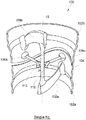
- the single figure shows a universal joint 100 in the general shape of an axisymmetric cylinder whose axis is labelled 15.
- the universal joint 100 comprises a first band 102a and a second band 102b.
- the two bands 102a-b are cylindrical bands which are coaxial with one another and which are arranged adjacent to one another in the direction of their common axis 15.
- a slot 104 separates the first band 102a from the second band 102b.
- the universal joint 100 comprises a first and a second stiffener 108a-b which extend inside the bands 102a-b.
- Each stiffener 108a-b is in the form of a blade.
- the first stiffener 108a extends in a first radial plane containing the common axis 15, and the second stiffener 108b extends in a second radial plane containing the common axis 15.
- the two radial planes are orthogonal.
- Each stiffener 108a-b has a first end and a second end.
- first and second ends are joined to the first band 102a
- second stiffener 108b the first and second ends are joined to the second band 102b.
- the universal joint 100 also comprises a stem 110 which is coaxial with the common axis 15 and of which a first end is joined to the first stiffener 108a and of which a second end is joined to the second stiffener 108b.
- the stem 110 transmits the axial forces applied to the universal joint 100.
- the flexibility of the stem 110 in flexion allows a connection of the ball type.
- the length and diameter of the stem 110 can be adjusted according to the desired flexibility.
- the universal joint 100 also comprises a crown 112 which is coaxial with the common axis 15 and which surrounds the stem 110, that is to say that the stem 110 is held captively in the crown 112.
- the internal diameter of the crown 112 is larger than the diameter of the stem 110 in order to limit contact between these two as the universal joint 100 deforms.
- the universal joint 100 also comprises four torsion bars 106a-b (of which only two are shown in the single figure). All of the torsion bars 106a-b extend inside the bands 102a-b in a single plane P perpendicular to the common axis 15.
- a first torsion bar 106a extends in the first radial plane and has a first end joined to the first band 102a and a second end joined to the crown 112.
- a second torsion bar 106b extends in the second radial plane and has a first end joined to the second band 102b and a second end joined to the crown 112.
- a third torsion bar extends in the first radial plane and has a first end joined to the first band 102a and a second end joined to the crown 112.
- a fourth torsion bar extends in the second radial plane and has a first end joined to the second band 102b and a second end joined to the crown 112.
- the four torsion bars 106a-b are distributed at regular angular intervals of 90° around the common axis 15, those torsion bars which are fixed to the same band 102a-b being coaxial.
- the torsion bars 106a-b deform in torsion.
- Each torsion bar 106a-b tends to deform by twisting about its axis.
- the combination of deformations about the two axes permits deformation about an axis coplanar with the torsion bars 106a-b.
- a universal joint 100 of this type thus has a simple shape without elements that move with respect to one another.
- the slot 104 has a profile that rises and falls, which allows each band 102a-b to pass successively from one side of the plane P to the other.
- the overall profile of the slot 104 is sinusoidal.
- the universal joint 100 may be made of any appropriate material such as metal or plastic.
Landscapes
- Engineering & Computer Science (AREA)
- General Engineering & Computer Science (AREA)
- Mechanical Engineering (AREA)
- Pivots And Pivotal Connections (AREA)
- Mutual Connection Of Rods And Tubes (AREA)
- Clamps And Clips (AREA)
Description
- The present invention relates to a universal joint having a simplified structure, i.e. having a reduced number of constituent parts and without frictional relative movement.
- A universal joint is a mechanical component which makes it possible to connect two elements such as shafts or tubes which may move relative to one another.
- A universal joint has a first axis which is aligned between the two elements. The universal joint permits two rotations, the axes of which are perpendicular to one another and perpendicular to the first axis.
- A universal joint consists of a number of parts that are movable relative to one another, which makes the joint bulky and generally heavy and also costly to produce.
- The present invention has the object of proposing a universal joint of simplified structure which does not have the disadvantages of the prior art and which in particular has a simple structure.
- To that end, there is provided a universal joint as set out in claim 1.
- A universal joint of this type thus makes it possible to provide articulation by elastic deformation with a simplified structure.
- The abovementioned features of the invention, as well as others, will become more clearly apparent upon reading the following description of an exemplary embodiment, said description being given with reference to the appended drawing, where the single figure is a perspective section view of a universal joint according to the invention.
- The single figure shows a
universal joint 100 in the general shape of an axisymmetric cylinder whose axis is labelled 15. - The
universal joint 100 comprises afirst band 102a and asecond band 102b. The twobands 102a-b are cylindrical bands which are coaxial with one another and which are arranged adjacent to one another in the direction of theircommon axis 15. - A
slot 104 separates thefirst band 102a from thesecond band 102b. - In order to ensure that the
bands 102a-b are held together, theuniversal joint 100 comprises a first and asecond stiffener 108a-b which extend inside thebands 102a-b. Eachstiffener 108a-b is in the form of a blade. - The
first stiffener 108a extends in a first radial plane containing thecommon axis 15, and thesecond stiffener 108b extends in a second radial plane containing thecommon axis 15. The two radial planes are orthogonal. - Each
stiffener 108a-b has a first end and a second end. For thefirst stiffener 108a, the first and second ends are joined to thefirst band 102a, and for thesecond stiffener 108b, the first and second ends are joined to thesecond band 102b. - The
universal joint 100 also comprises astem 110 which is coaxial with thecommon axis 15 and of which a first end is joined to thefirst stiffener 108a and of which a second end is joined to thesecond stiffener 108b. Thestem 110 transmits the axial forces applied to theuniversal joint 100. The flexibility of thestem 110 in flexion allows a connection of the ball type. The length and diameter of thestem 110 can be adjusted according to the desired flexibility. - The
universal joint 100 also comprises acrown 112 which is coaxial with thecommon axis 15 and which surrounds thestem 110, that is to say that thestem 110 is held captively in thecrown 112. The internal diameter of thecrown 112 is larger than the diameter of thestem 110 in order to limit contact between these two as theuniversal joint 100 deforms. - The
universal joint 100 also comprises fourtorsion bars 106a-b (of which only two are shown in the single figure). All of thetorsion bars 106a-b extend inside thebands 102a-b in a single plane P perpendicular to thecommon axis 15. - A
first torsion bar 106a extends in the first radial plane and has a first end joined to thefirst band 102a and a second end joined to thecrown 112. - A
second torsion bar 106b extends in the second radial plane and has a first end joined to thesecond band 102b and a second end joined to thecrown 112. - A third torsion bar extends in the first radial plane and has a first end joined to the
first band 102a and a second end joined to thecrown 112. - A fourth torsion bar extends in the second radial plane and has a first end joined to the
second band 102b and a second end joined to thecrown 112. - The four
torsion bars 106a-b are distributed at regular angular intervals of 90° around thecommon axis 15, those torsion bars which are fixed to thesame band 102a-b being coaxial. - When the
universal joint 100 is loaded, thetorsion bars 106a-b deform in torsion. Eachtorsion bar 106a-b tends to deform by twisting about its axis. The combination of deformations about the two axes permits deformation about an axis coplanar with thetorsion bars 106a-b. - A
universal joint 100 of this type thus has a simple shape without elements that move with respect to one another. - In order to attach the
torsion bars 106a-b to thebands 102a-b, theslot 104 has a profile that rises and falls, which allows eachband 102a-b to pass successively from one side of the plane P to the other. - In other words, in the embodiment of the invention shown in the single figure, when the
first band 102a passes above the plane P, the first andthird bars 106a are joined to thefirst band 102a at this passage. In the same way, when thesecond band 102b passes below the plane P, the second andfourth bars 106b are joined to thesecond band 102b at this passage. - In the embodiment of the invention presented here, the overall profile of the
slot 104 is sinusoidal. - Depending on the forces to which it is likely to be subjected, the
universal joint 100 may be made of any appropriate material such as metal or plastic.
Claims (1)
- Universal joint (100) comprising:- a first band (102a),- a second band (102b), the two bands (102a-b) being cylindrical bands coaxial with one another with respect to a common axis (15), the first band (102a) and the second band (102b) being separated by a slot (104),- a first and a second stiffener (108a-b) which extend inside the bands (102a-b), the first stiffener (108a) extending in a first radial plane containing the common axis (15), the second stiffener (108b) extending in a second radial plane orthogonal to the first radial plane and containing the common axis (15), each stiffener (108a-b) having a first end and a second end, the first and second ends of the first stiffener (108a) being joined to the first band (102a), and the first and second ends of the second stiffener (108b) being joined to the second band (102b),- a stem (110) which is coaxial with the common axis (15) and of which a first end is joined to the first stiffener (108a) and of which a second end is joined to the second stiffener (108b),- a crown (112) that is coaxial with the common axis (15) and surrounds the stem (110),- four torsion bars (106a-b) which extend inside the bands (102a-b) in a single plane P perpendicular to the common axis (15) and are distributed at regular angular intervals of 90° around the common axis (15), a first torsion bar (106a) extending in the first radial plane and having a first end joined to the first band (102a) and a second end joined to the crown (112), a second torsion bar (106b) extending in the second radial plane and having a first end joined to the second band (102b) and a second end joined to the crown (112), a third torsion bar extending in the first radial plane and having a first end joined to the first band (102a) and a second end joined to the crown (112), and a fourth torsion bar extending in the second radial plane and having a first end joined to the second band (102b) and a second end joined to the crown (112).
Applications Claiming Priority (1)
| Application Number | Priority Date | Filing Date | Title |
|---|---|---|---|
| FR1652433A FR3049320B1 (en) | 2016-03-22 | 2016-03-22 | CARDAN WITH SIMPLIFIED STRUCTURE |
Publications (2)
| Publication Number | Publication Date |
|---|---|
| EP3222865A1 EP3222865A1 (en) | 2017-09-27 |
| EP3222865B1 true EP3222865B1 (en) | 2018-05-09 |
Family
ID=55863084
Family Applications (1)
| Application Number | Title | Priority Date | Filing Date |
|---|---|---|---|
| EP17160221.2A Active EP3222865B1 (en) | 2016-03-22 | 2017-03-10 | Universal joint with simplified structure |
Country Status (4)
| Country | Link |
|---|---|
| US (1) | US9920789B2 (en) |
| EP (1) | EP3222865B1 (en) |
| CN (1) | CN107448467B (en) |
| FR (1) | FR3049320B1 (en) |
Families Citing this family (1)
| Publication number | Priority date | Publication date | Assignee | Title |
|---|---|---|---|---|
| FR3049319B1 (en) | 2016-03-22 | 2018-03-16 | Airbus Operations | CARDAN WITH SIMPLIFIED STRUCTURE |
Family Cites Families (20)
| Publication number | Priority date | Publication date | Assignee | Title |
|---|---|---|---|---|
| US1602912A (en) * | 1923-03-15 | 1926-10-12 | Int Motor Co | Universal joint |
| US1952970A (en) * | 1930-06-07 | 1934-03-27 | Malcus Holmquist Ab | Resilient shaft coupling |
| US3081991A (en) * | 1960-07-12 | 1963-03-19 | Northrop Corp | Transverse supported torsion bar |
| US3277555A (en) | 1963-05-22 | 1966-10-11 | Bendix Corp | Clip flexural pivot manufacturing method |
| US3360255A (en) * | 1965-06-11 | 1967-12-26 | Alfred N Ormond | Universal flexure unit |
| US3427828A (en) * | 1966-12-16 | 1969-02-18 | Gen Precision Systems Inc | Gyro with flexure hinge |
| SE339776B (en) * | 1967-04-07 | 1971-10-18 | F Hector | |
| US3722296A (en) | 1971-01-19 | 1973-03-27 | Bendix Corp | Antifriction bearing with compensating flexural pivot in a free axis gyroscope |
| US3807029A (en) | 1972-09-05 | 1974-04-30 | Bendix Corp | Method of making a flexural pivot |
| US3813089A (en) | 1972-09-08 | 1974-05-28 | Bendix Corp | Eccentric flexural pivot |
| US4438655A (en) * | 1976-11-15 | 1984-03-27 | Sperry Corporation | Flexure suspension for free rotor gyroscopes |
| US4405184A (en) | 1981-03-16 | 1983-09-20 | The United States Of America As Represented By The Administrator Of The National Aeonautics And Space Administration | Unidirectional flexural pivot |
| DE3241373A1 (en) * | 1982-11-09 | 1984-05-10 | Anschütz & Co GmbH, 2300 Kiel | SPRING JOINT |
| US4812072A (en) | 1988-03-11 | 1989-03-14 | Santa Barbara Research Center | Torsion structural pivot |
| US4802784A (en) | 1988-03-11 | 1989-02-07 | Santa Barbara Research Center | Bi-flex pivot |
| US5061107A (en) * | 1989-12-22 | 1991-10-29 | Santa Barbara Research Center | Torflex pivot |
| US5529277A (en) * | 1994-09-20 | 1996-06-25 | Ball Corporation | Suspension system having two degrees of rotational freedom |
| DE10330947B4 (en) * | 2003-07-08 | 2015-10-29 | Schenck Process Gmbh | Cross spring element |
| CN104791377A (en) * | 2015-03-26 | 2015-07-22 | 哈尔滨工业大学 | Double-reed large-turning angle flexible joint |
| FR3049319B1 (en) | 2016-03-22 | 2018-03-16 | Airbus Operations | CARDAN WITH SIMPLIFIED STRUCTURE |
-
2016
- 2016-03-22 FR FR1652433A patent/FR3049320B1/en not_active Expired - Fee Related
-
2017
- 2017-03-10 EP EP17160221.2A patent/EP3222865B1/en active Active
- 2017-03-21 CN CN201710171055.2A patent/CN107448467B/en active Active
- 2017-03-22 US US15/466,478 patent/US9920789B2/en active Active
Non-Patent Citations (1)
| Title |
|---|
| None * |
Also Published As
| Publication number | Publication date |
|---|---|
| CN107448467B (en) | 2019-03-01 |
| FR3049320B1 (en) | 2018-03-16 |
| CN107448467A (en) | 2017-12-08 |
| EP3222865A1 (en) | 2017-09-27 |
| US20170276188A1 (en) | 2017-09-28 |
| FR3049320A1 (en) | 2017-09-29 |
| US9920789B2 (en) | 2018-03-20 |
Similar Documents
| Publication | Publication Date | Title |
|---|---|---|
| US20160052143A1 (en) | Concave bearing outer race for tendon based robotic joints | |
| US20160102724A1 (en) | Concentric Arc Spline Rotational Spring | |
| US9796092B2 (en) | Multi-articulated manipulator | |
| JP2017509391A5 (en) | ||
| US10641316B2 (en) | Bearing sleeve for a shaft | |
| US20160018029A1 (en) | Cable bend limiter | |
| US9759298B2 (en) | Roller screw mechanism | |
| EP3222865A1 (en) | Universal joint with simplified structure | |
| EP3222866B1 (en) | Universal joint with simplified structure | |
| EP1335225B1 (en) | Spacer for lens system | |
| EP3070372A1 (en) | Rack shaft and steering system | |
| CN104603479B (en) | Fixing ring for fixing the screw on the support and the assembly obtained | |
| US11661968B1 (en) | Method for assembling a flexure bearing | |
| DE102014204130B3 (en) | Force measuring device with pivot bearing | |
| EP2840265A2 (en) | Retainer cap for shaft assembly | |
| EP2147828A1 (en) | Low shock frangible joint | |
| US11387720B2 (en) | Retaining apparatus, retaining method and insert method of wave winding coil | |
| EP0747605A1 (en) | Tubular component for telescopic propeller shaft | |
| EP2937579A1 (en) | Compression rod having a buckling initiating feature | |
| JP6854166B2 (en) | Universal joint | |
| US9683608B2 (en) | Universal joint bearing, joint cross, universal joint, and multi-row needle roller bearing | |
| EP4459144A1 (en) | Retainer and bearing device | |
| JP2015204686A (en) | Bent part fixing structure of wire harness | |
| JP2004324885A (en) | Method and apparatus for assembling a constant velocity joint | |
| US20190048957A1 (en) | Low torsion bushing and assembly |
Legal Events
| Date | Code | Title | Description |
|---|---|---|---|
| PUAI | Public reference made under article 153(3) epc to a published international application that has entered the european phase |
Free format text: ORIGINAL CODE: 0009012 |
|
| STAA | Information on the status of an ep patent application or granted ep patent |
Free format text: STATUS: REQUEST FOR EXAMINATION WAS MADE |
|
| 17P | Request for examination filed |
Effective date: 20170310 |
|
| AK | Designated contracting states |
Kind code of ref document: A1 Designated state(s): AL AT BE BG CH CY CZ DE DK EE ES FI FR GB GR HR HU IE IS IT LI LT LU LV MC MK MT NL NO PL PT RO RS SE SI SK SM TR |
|
| AX | Request for extension of the european patent |
Extension state: BA ME |
|
| GRAP | Despatch of communication of intention to grant a patent |
Free format text: ORIGINAL CODE: EPIDOSNIGR1 |
|
| STAA | Information on the status of an ep patent application or granted ep patent |
Free format text: STATUS: GRANT OF PATENT IS INTENDED |
|
| RIC1 | Information provided on ipc code assigned before grant |
Ipc: F16D 3/00 20060101AFI20171018BHEP Ipc: F16D 3/56 20060101ALI20171018BHEP |
|
| INTG | Intention to grant announced |
Effective date: 20171117 |
|
| GRAS | Grant fee paid |
Free format text: ORIGINAL CODE: EPIDOSNIGR3 |
|
| GRAA | (expected) grant |
Free format text: ORIGINAL CODE: 0009210 |
|
| STAA | Information on the status of an ep patent application or granted ep patent |
Free format text: STATUS: THE PATENT HAS BEEN GRANTED |
|
| RBV | Designated contracting states (corrected) |
Designated state(s): AL AT BE BG CH CY CZ DE DK EE ES FI FR GB GR HR HU IE IS IT LI LT LU LV MC MK MT NL NO PL PT RO RS SE SI SK SM TR |
|
| AK | Designated contracting states |
Kind code of ref document: B1 Designated state(s): AL AT BE BG CH CY CZ DE DK EE ES FI FR GB GR HR HU IE IS IT LI LT LU LV MC MK MT NL NO PL PT RO RS SE SI SK SM TR |
|
| REG | Reference to a national code |
Ref country code: GB Ref legal event code: FG4D |
|
| REG | Reference to a national code |
Ref country code: CH Ref legal event code: EP Ref country code: AT Ref legal event code: REF Ref document number: 997834 Country of ref document: AT Kind code of ref document: T Effective date: 20180515 |
|
| REG | Reference to a national code |
Ref country code: IE Ref legal event code: FG4D |
|
| REG | Reference to a national code |
Ref country code: DE Ref legal event code: R096 Ref document number: 602017000053 Country of ref document: DE |
|
| REG | Reference to a national code |
Ref country code: NL Ref legal event code: MP Effective date: 20180509 |
|
| REG | Reference to a national code |
Ref country code: LT Ref legal event code: MG4D |
|
| PG25 | Lapsed in a contracting state [announced via postgrant information from national office to epo] |
Ref country code: NO Free format text: LAPSE BECAUSE OF FAILURE TO SUBMIT A TRANSLATION OF THE DESCRIPTION OR TO PAY THE FEE WITHIN THE PRESCRIBED TIME-LIMIT Effective date: 20180809 Ref country code: SE Free format text: LAPSE BECAUSE OF FAILURE TO SUBMIT A TRANSLATION OF THE DESCRIPTION OR TO PAY THE FEE WITHIN THE PRESCRIBED TIME-LIMIT Effective date: 20180509 Ref country code: BG Free format text: LAPSE BECAUSE OF FAILURE TO SUBMIT A TRANSLATION OF THE DESCRIPTION OR TO PAY THE FEE WITHIN THE PRESCRIBED TIME-LIMIT Effective date: 20180809 Ref country code: LT Free format text: LAPSE BECAUSE OF FAILURE TO SUBMIT A TRANSLATION OF THE DESCRIPTION OR TO PAY THE FEE WITHIN THE PRESCRIBED TIME-LIMIT Effective date: 20180509 Ref country code: FI Free format text: LAPSE BECAUSE OF FAILURE TO SUBMIT A TRANSLATION OF THE DESCRIPTION OR TO PAY THE FEE WITHIN THE PRESCRIBED TIME-LIMIT Effective date: 20180509 |
|
| PG25 | Lapsed in a contracting state [announced via postgrant information from national office to epo] |
Ref country code: GR Free format text: LAPSE BECAUSE OF FAILURE TO SUBMIT A TRANSLATION OF THE DESCRIPTION OR TO PAY THE FEE WITHIN THE PRESCRIBED TIME-LIMIT Effective date: 20180810 Ref country code: LV Free format text: LAPSE BECAUSE OF FAILURE TO SUBMIT A TRANSLATION OF THE DESCRIPTION OR TO PAY THE FEE WITHIN THE PRESCRIBED TIME-LIMIT Effective date: 20180509 Ref country code: HR Free format text: LAPSE BECAUSE OF FAILURE TO SUBMIT A TRANSLATION OF THE DESCRIPTION OR TO PAY THE FEE WITHIN THE PRESCRIBED TIME-LIMIT Effective date: 20180509 Ref country code: NL Free format text: LAPSE BECAUSE OF FAILURE TO SUBMIT A TRANSLATION OF THE DESCRIPTION OR TO PAY THE FEE WITHIN THE PRESCRIBED TIME-LIMIT Effective date: 20180509 Ref country code: RS Free format text: LAPSE BECAUSE OF FAILURE TO SUBMIT A TRANSLATION OF THE DESCRIPTION OR TO PAY THE FEE WITHIN THE PRESCRIBED TIME-LIMIT Effective date: 20180509 |
|
| REG | Reference to a national code |
Ref country code: AT Ref legal event code: MK05 Ref document number: 997834 Country of ref document: AT Kind code of ref document: T Effective date: 20180509 |
|
| PG25 | Lapsed in a contracting state [announced via postgrant information from national office to epo] |
Ref country code: AT Free format text: LAPSE BECAUSE OF FAILURE TO SUBMIT A TRANSLATION OF THE DESCRIPTION OR TO PAY THE FEE WITHIN THE PRESCRIBED TIME-LIMIT Effective date: 20180509 Ref country code: RO Free format text: LAPSE BECAUSE OF FAILURE TO SUBMIT A TRANSLATION OF THE DESCRIPTION OR TO PAY THE FEE WITHIN THE PRESCRIBED TIME-LIMIT Effective date: 20180509 Ref country code: CZ Free format text: LAPSE BECAUSE OF FAILURE TO SUBMIT A TRANSLATION OF THE DESCRIPTION OR TO PAY THE FEE WITHIN THE PRESCRIBED TIME-LIMIT Effective date: 20180509 Ref country code: PL Free format text: LAPSE BECAUSE OF FAILURE TO SUBMIT A TRANSLATION OF THE DESCRIPTION OR TO PAY THE FEE WITHIN THE PRESCRIBED TIME-LIMIT Effective date: 20180509 Ref country code: DK Free format text: LAPSE BECAUSE OF FAILURE TO SUBMIT A TRANSLATION OF THE DESCRIPTION OR TO PAY THE FEE WITHIN THE PRESCRIBED TIME-LIMIT Effective date: 20180509 Ref country code: EE Free format text: LAPSE BECAUSE OF FAILURE TO SUBMIT A TRANSLATION OF THE DESCRIPTION OR TO PAY THE FEE WITHIN THE PRESCRIBED TIME-LIMIT Effective date: 20180509 Ref country code: SK Free format text: LAPSE BECAUSE OF FAILURE TO SUBMIT A TRANSLATION OF THE DESCRIPTION OR TO PAY THE FEE WITHIN THE PRESCRIBED TIME-LIMIT Effective date: 20180509 |
|
| REG | Reference to a national code |
Ref country code: DE Ref legal event code: R097 Ref document number: 602017000053 Country of ref document: DE |
|
| PG25 | Lapsed in a contracting state [announced via postgrant information from national office to epo] |
Ref country code: IT Free format text: LAPSE BECAUSE OF FAILURE TO SUBMIT A TRANSLATION OF THE DESCRIPTION OR TO PAY THE FEE WITHIN THE PRESCRIBED TIME-LIMIT Effective date: 20180509 Ref country code: SM Free format text: LAPSE BECAUSE OF FAILURE TO SUBMIT A TRANSLATION OF THE DESCRIPTION OR TO PAY THE FEE WITHIN THE PRESCRIBED TIME-LIMIT Effective date: 20180509 |
|
| PLBE | No opposition filed within time limit |
Free format text: ORIGINAL CODE: 0009261 |
|
| STAA | Information on the status of an ep patent application or granted ep patent |
Free format text: STATUS: NO OPPOSITION FILED WITHIN TIME LIMIT |
|
| 26N | No opposition filed |
Effective date: 20190212 |
|
| PG25 | Lapsed in a contracting state [announced via postgrant information from national office to epo] |
Ref country code: ES Free format text: LAPSE BECAUSE OF FAILURE TO SUBMIT A TRANSLATION OF THE DESCRIPTION OR TO PAY THE FEE WITHIN THE PRESCRIBED TIME-LIMIT Effective date: 20180509 |
|
| PG25 | Lapsed in a contracting state [announced via postgrant information from national office to epo] |
Ref country code: MC Free format text: LAPSE BECAUSE OF FAILURE TO SUBMIT A TRANSLATION OF THE DESCRIPTION OR TO PAY THE FEE WITHIN THE PRESCRIBED TIME-LIMIT Effective date: 20180509 |
|
| PG25 | Lapsed in a contracting state [announced via postgrant information from national office to epo] |
Ref country code: AL Free format text: LAPSE BECAUSE OF FAILURE TO SUBMIT A TRANSLATION OF THE DESCRIPTION OR TO PAY THE FEE WITHIN THE PRESCRIBED TIME-LIMIT Effective date: 20180509 Ref country code: LU Free format text: LAPSE BECAUSE OF NON-PAYMENT OF DUE FEES Effective date: 20190310 |
|
| REG | Reference to a national code |
Ref country code: BE Ref legal event code: MM Effective date: 20190331 |
|
| PG25 | Lapsed in a contracting state [announced via postgrant information from national office to epo] |
Ref country code: IE Free format text: LAPSE BECAUSE OF NON-PAYMENT OF DUE FEES Effective date: 20190310 |
|
| PG25 | Lapsed in a contracting state [announced via postgrant information from national office to epo] |
Ref country code: BE Free format text: LAPSE BECAUSE OF NON-PAYMENT OF DUE FEES Effective date: 20190331 |
|
| PG25 | Lapsed in a contracting state [announced via postgrant information from national office to epo] |
Ref country code: TR Free format text: LAPSE BECAUSE OF FAILURE TO SUBMIT A TRANSLATION OF THE DESCRIPTION OR TO PAY THE FEE WITHIN THE PRESCRIBED TIME-LIMIT Effective date: 20180509 |
|
| PG25 | Lapsed in a contracting state [announced via postgrant information from national office to epo] |
Ref country code: MT Free format text: LAPSE BECAUSE OF NON-PAYMENT OF DUE FEES Effective date: 20190310 Ref country code: PT Free format text: LAPSE BECAUSE OF FAILURE TO SUBMIT A TRANSLATION OF THE DESCRIPTION OR TO PAY THE FEE WITHIN THE PRESCRIBED TIME-LIMIT Effective date: 20180910 |
|
| REG | Reference to a national code |
Ref country code: CH Ref legal event code: PL |
|
| PG25 | Lapsed in a contracting state [announced via postgrant information from national office to epo] |
Ref country code: CH Free format text: LAPSE BECAUSE OF NON-PAYMENT OF DUE FEES Effective date: 20200331 Ref country code: LI Free format text: LAPSE BECAUSE OF NON-PAYMENT OF DUE FEES Effective date: 20200331 |
|
| PG25 | Lapsed in a contracting state [announced via postgrant information from national office to epo] |
Ref country code: CY Free format text: LAPSE BECAUSE OF FAILURE TO SUBMIT A TRANSLATION OF THE DESCRIPTION OR TO PAY THE FEE WITHIN THE PRESCRIBED TIME-LIMIT Effective date: 20180509 |
|
| PG25 | Lapsed in a contracting state [announced via postgrant information from national office to epo] |
Ref country code: IS Free format text: LAPSE BECAUSE OF FAILURE TO SUBMIT A TRANSLATION OF THE DESCRIPTION OR TO PAY THE FEE WITHIN THE PRESCRIBED TIME-LIMIT Effective date: 20180909 |
|
| PG25 | Lapsed in a contracting state [announced via postgrant information from national office to epo] |
Ref country code: HU Free format text: LAPSE BECAUSE OF FAILURE TO SUBMIT A TRANSLATION OF THE DESCRIPTION OR TO PAY THE FEE WITHIN THE PRESCRIBED TIME-LIMIT; INVALID AB INITIO Effective date: 20170310 |
|
| PG25 | Lapsed in a contracting state [announced via postgrant information from national office to epo] |
Ref country code: SI Free format text: LAPSE BECAUSE OF FAILURE TO SUBMIT A TRANSLATION OF THE DESCRIPTION OR TO PAY THE FEE WITHIN THE PRESCRIBED TIME-LIMIT Effective date: 20180509 |
|
| PG25 | Lapsed in a contracting state [announced via postgrant information from national office to epo] |
Ref country code: MK Free format text: LAPSE BECAUSE OF FAILURE TO SUBMIT A TRANSLATION OF THE DESCRIPTION OR TO PAY THE FEE WITHIN THE PRESCRIBED TIME-LIMIT Effective date: 20180509 |
|
| PGFP | Annual fee paid to national office [announced via postgrant information from national office to epo] |
Ref country code: DE Payment date: 20240320 Year of fee payment: 8 |
|
| REG | Reference to a national code |
Ref country code: DE Ref legal event code: R119 Ref document number: 602017000053 Country of ref document: DE |
|
| PG25 | Lapsed in a contracting state [announced via postgrant information from national office to epo] |
Ref country code: DE Free format text: LAPSE BECAUSE OF NON-PAYMENT OF DUE FEES Effective date: 20251001 |
|
| PGFP | Annual fee paid to national office [announced via postgrant information from national office to epo] |
Ref country code: GB Payment date: 20260324 Year of fee payment: 10 |
|
| PGFP | Annual fee paid to national office [announced via postgrant information from national office to epo] |
Ref country code: FR Payment date: 20260320 Year of fee payment: 10 |