EP3222852A1 - Compressor and method of designing compressor - Google Patents
Compressor and method of designing compressor Download PDFInfo
- Publication number
- EP3222852A1 EP3222852A1 EP17162259.0A EP17162259A EP3222852A1 EP 3222852 A1 EP3222852 A1 EP 3222852A1 EP 17162259 A EP17162259 A EP 17162259A EP 3222852 A1 EP3222852 A1 EP 3222852A1
- Authority
- EP
- European Patent Office
- Prior art keywords
- compressor
- main body
- cover
- rotary shaft
- reinforcing parts
- Prior art date
- Legal status (The legal status is an assumption and is not a legal conclusion. Google has not performed a legal analysis and makes no representation as to the accuracy of the status listed.)
- Granted
Links
Images



Classifications
-
- F—MECHANICAL ENGINEERING; LIGHTING; HEATING; WEAPONS; BLASTING
- F04—POSITIVE - DISPLACEMENT MACHINES FOR LIQUIDS; PUMPS FOR LIQUIDS OR ELASTIC FLUIDS
- F04C—ROTARY-PISTON, OR OSCILLATING-PISTON, POSITIVE-DISPLACEMENT MACHINES FOR LIQUIDS; ROTARY-PISTON, OR OSCILLATING-PISTON, POSITIVE-DISPLACEMENT PUMPS
- F04C18/00—Rotary-piston pumps specially adapted for elastic fluids
- F04C18/02—Rotary-piston pumps specially adapted for elastic fluids of arcuate-engagement type, i.e. with circular translatory movement of co-operating members, each member having the same number of teeth or tooth-equivalents
- F04C18/0207—Rotary-piston pumps specially adapted for elastic fluids of arcuate-engagement type, i.e. with circular translatory movement of co-operating members, each member having the same number of teeth or tooth-equivalents both members having co-operating elements in spiral form
- F04C18/0215—Rotary-piston pumps specially adapted for elastic fluids of arcuate-engagement type, i.e. with circular translatory movement of co-operating members, each member having the same number of teeth or tooth-equivalents both members having co-operating elements in spiral form where only one member is moving
-
- F—MECHANICAL ENGINEERING; LIGHTING; HEATING; WEAPONS; BLASTING
- F01—MACHINES OR ENGINES IN GENERAL; ENGINE PLANTS IN GENERAL; STEAM ENGINES
- F01C—ROTARY-PISTON OR OSCILLATING-PISTON MACHINES OR ENGINES
- F01C21/00—Component parts, details or accessories not provided for in groups F01C1/00 - F01C20/00
- F01C21/10—Outer members for co-operation with rotary pistons; Casings
-
- F—MECHANICAL ENGINEERING; LIGHTING; HEATING; WEAPONS; BLASTING
- F04—POSITIVE - DISPLACEMENT MACHINES FOR LIQUIDS; PUMPS FOR LIQUIDS OR ELASTIC FLUIDS
- F04C—ROTARY-PISTON, OR OSCILLATING-PISTON, POSITIVE-DISPLACEMENT MACHINES FOR LIQUIDS; ROTARY-PISTON, OR OSCILLATING-PISTON, POSITIVE-DISPLACEMENT PUMPS
- F04C2240/00—Components
- F04C2240/30—Casings or housings
-
- F—MECHANICAL ENGINEERING; LIGHTING; HEATING; WEAPONS; BLASTING
- F04—POSITIVE - DISPLACEMENT MACHINES FOR LIQUIDS; PUMPS FOR LIQUIDS OR ELASTIC FLUIDS
- F04C—ROTARY-PISTON, OR OSCILLATING-PISTON, POSITIVE-DISPLACEMENT MACHINES FOR LIQUIDS; ROTARY-PISTON, OR OSCILLATING-PISTON, POSITIVE-DISPLACEMENT PUMPS
- F04C2270/00—Control; Monitoring or safety arrangements
- F04C2270/12—Vibration
-
- F—MECHANICAL ENGINEERING; LIGHTING; HEATING; WEAPONS; BLASTING
- F04—POSITIVE - DISPLACEMENT MACHINES FOR LIQUIDS; PUMPS FOR LIQUIDS OR ELASTIC FLUIDS
- F04C—ROTARY-PISTON, OR OSCILLATING-PISTON, POSITIVE-DISPLACEMENT MACHINES FOR LIQUIDS; ROTARY-PISTON, OR OSCILLATING-PISTON, POSITIVE-DISPLACEMENT PUMPS
- F04C2270/00—Control; Monitoring or safety arrangements
- F04C2270/15—Resonance
Definitions
- the present invention relates to a compressor and a method of designing a compressor.
- Compressors such as a scroll compressor configured to send a working fluid such as a refrigerant under pressure using a rotational motion of a scroll are known.
- a scroll compressor a refrigerant compressed using a scroll is periodically discharged to a discharge space in response to a rotational period of the scroll (for example, refer to Japanese Unexamined Patent Application, First Publication No. 2001-336484 ).
- the discharge space is a space surrounded by a housing or a cover of the compressor, and a compressed refrigerant is discharged to another system through a discharge pipe provided in the cover.
- pressure pulsation occurs when a refrigerant is periodically discharged to a discharge space through a discharge port of a scroll.
- pressure pulsation coincides with a natural frequency of the discharge space, resonance may occur in some cases.
- the cover vibrates due to such resonance so that noise may occur.
- the present invention aims at providing a compressor capable of reducing noise at a cover due to resonance in a compressor configured to periodically compress and discharge a fluid to a discharge space.
- a compressor includes: a rotary shaft rotatably driven; a compressor main body configured to periodically compress and discharge a fluid using rotation of the rotary shaft; and a cover provided with a cover main body having a discharge space into which the fluid discharged from the compressor main body is introduced, and a plurality of reinforcing parts provided on at least one of an outer surface and an inner surface of the cover main body and extending along at least one of the outer surface and the inner surface thereof.
- reinforcing parts are formed at the cover so that vibrations of the cover which occur due to resonance occurring in response to the periodically discharged fluid and the discharge space can be minimized.
- the compressor may include: an electric motor configured to rotatably drive the rotary shaft about an axis; and a housing having a cylindrical shape along the axis and accommodating the electric motor, the rotary shaft, and the compressor main body, wherein the cover may be an upper cover configured to close one end of the housing.
- the housing may have a cylindrical shape
- the cover main body may have a circular shape when viewed from the axial direction
- the reinforcing parts may extend radially from a center of the cover main body.
- the reinforcing parts may extend in a circumferential direction with respect to the center of the cover main body.
- the cover main body may have a polygonal pyramid shape having a top part protruding in the axial direction, and the reinforcing parts may be oblique ridges of the cover main body.
- a method of designing a compressor includes: a compressor designing step of designing the compressor including a compressor main body including a rotary shaft rotatably driven and configured to periodically compress and discharge a fluid using rotation of the rotary shaft and a cover defining a discharge space into which the fluid discharged from the compressor main body is introduced; a resonance mode measuring step of measuring a resonance mode occurring in the discharge space using a compressor model modeled on the basis of the compressor designed in the compressor designing step; and a reinforcing part designing step of designing a plurality of reinforcing parts, the plurality of reinforcing parts being provided on at least one of an outer surface and an inner surface of the cover to pass through antinodes of the resonance mode on the basis of the resonance mode measured in the resonance mode measuring step and extending along at least one of the outer surface and the inner surface of the cover.
- reinforcing parts are formed at a cover so that vibrations of the cover which occur due to resonance occurring in response to periodically discharged fluid and a discharge space can be minimized.
- the compressor of this embodiment is a scroll compressor in which a turning scroll performs a turning motion, a compression chamber volume is decreased as a compression chamber formed between the turning scroll and a fixed scroll is moved to a central portion, and thus a compression action is performed.
- the scroll compressor of this embodiment is used for a refrigeration cycle and a working fluid is a refrigerant.
- a scroll compressor 1 has an electric motor 3, a rotary shaft 2 rotatably driven about an axis O1 by the electric motor 3, a compressor main body 4 configured to compress and discharge a refrigerant using rotation of the rotary shaft 2, a housing 5 accommodating the rotary shaft 2, the electric motor 3, and the compressor main body 4, an upper cover 6 closing one end at first side D1 in an axial direction of the housing 5, and a lower cover 7 closing the second side D2 in the axial direction of the housing 5.
- a direction in which the axis O1 of the rotary shaft 2 extends is an axial direction D.
- a direction perpendicular to the axis O1 is a radial direction
- a side away from the axis O1 in the radial direction is referred to as an outer side in the radial direction
- a side close to the axis O1 in the radial direction is referred to as an inner side in the radial direction.
- An upper side in FIG. 1 in the axial direction D is referred to as a first side D1 in the axial direction and a lower side in FIG. 1 in the axial direction D is referred to as a second side D2 in the axial direction.
- the compressor main body 4 compresses the refrigerant using rotational energy of the rotary shaft 2 and discharges the compressed refrigerant in a high pressure state to an outside thereof.
- the compressor main body 4 has a fixed scroll 17 and a turning scroll 18.
- a discharge cover 8 is a substantially disc-shaped member that partitions a space inside the housing 5 in the axial direction D.
- a discharge chamber 15 (a discharge space) is a space formed by the discharge cover 8 and the upper cover 6.
- the discharge chamber 15 is the space into which the refrigerant discharged from the compressor main body 4 is introduced.
- a discharge port 20 through which the compressed refrigerant flows to the discharge chamber 15 and a discharge valve 21 configured to prevent reversely flowing of the refrigerant from a high pressure side are provided at a central portion of the discharge cover 8.
- the discharge chamber 15 of this embodiment is formed of the upper cover 6 and the discharge cover 8, the present invention is not limited thereto.
- the discharge chamber 15 may be formed of the upper cover 6 and a surface of the fixed scroll 17 which faces the first side D1 in the axial direction and may be formed by only the upper cover 6.
- a suction pipe 9 configured to suction the refrigerant from an outside thereof is provided on the housing 5.
- a discharge pipe 10 configured to discharge the compressed refrigerant inside the discharge chamber 15 after being compressed by the compressor main body 4 is provided on the upper cover 6.
- the rotary shaft 2 has a cylindrical shape about the axis O1.
- the rotary shaft 2 is rotatably supported inside the housing 5 by a main bearing 11 provided at the first side D1 in the axial direction and a sub bearing 13 provided at the second side D2 in the axial direction.
- a main bearing main body 12 is attached between the main bearing 11 and an outer peripheral surface of the rotary shaft 2.
- a sub bearing main body 14 is attached between the sub bearing 13 and the outer peripheral surface of the rotary shaft 2.
- an eccentric shaft 16 having a columnar shape about an eccentric axis 02 different from the axis O1 is provided at a position which is offset (eccentric) with respect to the axis O1.
- the eccentric axis 02 is parallel to the axis O1.
- the eccentric shaft 16 has a cylindrical shape which protrudes from an end portion of the rotary shaft 2 toward the first side D1 in the axial direction. Therefore, the eccentric shaft 16 revolves about the axis O1 of the rotary shaft 2 in a state in which the rotary shaft 2 rotates about the axis O1.
- the fixed scroll 17 is a substantially discoid member fixed inside the housing 5.
- the turning scroll 18 faces the fixed scroll 17 from the axial direction D and thus a compression chamber C is formed between both scrolls.
- the fixed scroll 17 is a fixed end plate 25 having a disc shape and a fixed wrap 26 standing up in the axial direction D from a surface of the fixed end plate 25 at the second side D2 thereof in the axial direction.
- the fixed end plate 25 extends along a surface which is substantially perpendicular to the axis O1.
- the fixed wrap 26 is a wall body which is spirally formed when viewed from the axial direction D.
- the fixed wrap 26 is formed of plate-like members being wound about a center of the fixed end plate 25.
- the fixed wrap 26 is preferably constituted to form an involute curve about the axis O1 when viewed from the axial direction D.
- An outer peripheral wall 27 extending in a tubular shape along an outer circumference of the fixed end plate 25 is formed at the outer side of the fixed wrap 26 in the radial direction.
- An annular flange part 28 widening outward in the radial direction is provided at an edge of the outer peripheral wall 27 at the second side D2 in the axial direction.
- the fixed scroll 17 is fixed to the main bearing 11 using bolts or the like via the flange part 28.
- a fixed scroll discharge port 29 is formed at a central portion of a spiral of the fixed scroll 17.
- the turning scroll 18 has a turning end plate 23 having a disc shape and a spiral turning wrap 31 provided at a surface of the turning end plate 23 at the first side D1 in the axial direction.
- the turning wrap 31 is also preferably constituted to form an involute curve about the axis O1.
- the turning wrap 31 and the fixed wrap 26 are disposed to face each other from the axial direction D and to overlap each other in a direction crossing the axis O1.
- the fixed wrap 26 is engaged with the turning wrap 31.
- a predetermined space is formed between the fixed wrap 26 and the turning wrap 31 in such an engaged state.
- a volume of the space is changed according to the turning of the turning wrap 31.
- the refrigerant can be compressed.
- a boss part 30 having a cylindrical shape is formed at a surface of the turning end plate 23 at the second side D2 in the axial direction.
- a central axis of the boss part 30 is coaxial with the eccentric axis 02.
- the eccentric shaft 16 formed on the rotary shaft 2 is fit into a space inside the boss part 30 via a dry bush 32 from the axial direction D.
- a turning bearing 33 is attached between the dry bush 32 and the boss part 30.
- An Oldham ring 22 configured to restrict rotation of the turning scroll 18 (rotation about the eccentric axis 02) is provided at the main bearing 11.
- a protrusion formed on the Oldham ring 22 is fitted into a groove formed in the turning end plate 23 of the turning scroll 18.
- a thrust bearing 24 is provided at the inner side of the Oldham ring 22 in the radial direction when viewed from the Oldham ring 22. The thrust bearing 24 supports a load in the axial direction D due to the turning scroll 18.
- the upper cover 6 of this embodiment will be described.
- the upper cover 6 has an upper cover main body 34 forming the discharge chamber 15 (refer to Fig. 1 ) and reinforcing parts 37 (ribs) provided on an outer surface 34a of the upper cover main body 34.
- the upper cover main body 34 has a circular shape when viewed from the axial direction D and forms part of the discharge chamber 15.
- the upper cover main body 34 has a cylindrical part 35 with a cylindrical shape and a dome part 36 configured to block the first side D1 of the cylindrical part 35 in the axial direction.
- the dome part 36 has a spherical shape.
- the dome part 36 is smoothly connected to the cylindrical part 35.
- the plurality of reinforcing parts 37 extending along the outer surface 34a of the upper cover main body 34 are formed on the outer surface 34a of the upper cover main body 34.
- the reinforcing parts 37 radially extend from a center T1 of the upper cover main body 34.
- a center T1 of the upper cover 6 is a point at which the axis O1 crosses the upper cover 6.
- the plurality of reinforcing parts 37 are formed at intervals in a circumferential direction.
- the plurality of reinforcing parts 37 are preferably formed at equal intervals in the circumferential direction.
- the reinforcing parts 37 are protrusions protruding from the outer surface 34a of the upper cover main body 34.
- the reinforcing parts 37 have a function of reinforcing the upper cover main body 34.
- the method of designing the scroll compressor 1 has a compressor designing step, a resonance mode measuring step, and a reinforcing part designing step.
- the compressor designing step is a step of designing a scroll compressor on the basis of a required performance or specification or the like.
- a designer performs selection (design) of an electric motor, design of a scroll, and design of shapes or the like of a housing and an upper cover.
- a specification of an electric motor and a shape of a discharge chamber or the like are determined.
- the resonance mode measuring step is a step of performing a simulation on a computer using a compressor model (an analysis model) modeled on the basis of the scroll compressor designed in the compressor designing step and measuring a resonance mode (an acoustic eigenvalue and acoustic characteristics) occurring in a discharge chamber.
- a compressor model an analysis model
- a resonance mode an acoustic eigenvalue and acoustic characteristics
- a compressor model which can be input to the computer is created on the basis of the designed scroll compressor. Subsequently, a behavior of the compressor model is simulated on the computer using analysis software or the like.
- the refrigerant compressed in the compressor main body 4 (a scroll) is periodically discharged from the fixed scroll discharge port 29 of the fixed scroll 17.
- the refrigerant that has passed through the fixed scroll discharge port 29 passes through a space between the fixed scroll 17 and the discharge cover 8.
- the refrigerant passes through the discharge port 20 of the discharge cover 8, enters into the discharge chamber 15 defined by the upper cover 6, and is discharged through the discharge pipe 10.
- FIG. 3 illustrates a resonance mode of the discharge chamber 15 measured through a simulation. Furthermore, a resonance frequency is specified through the simulation. In the case of the scroll compressor 1 of this embodiment, the resonance frequency is 4 kHz to 5 kHz.
- symbols + indicate positions at which a pressure is high due to resonance
- symbols - indicate positions at which the pressure is low due to the resonance
- these positions are antinodes of a resonance mode.
- the resonance mode is not limited to a case shown in FIG. 3 and changes in accordance with a shape or the like of the discharge chamber 15. For example, intervals of the antinodes of the resonance mode in a circumferential direction change in accordance with a rotational speed or the like of the rotary shaft 2.
- the reinforcing parts 37 are designed on the outer surface 34a of the upper cover main body 34 on the basis of positions of the antinodes of the resonance mode measured in the resonance mode measuring step. To be specific, the reinforcing parts 37 are designed to pass through the antinodes of the resonance mode.
- the reinforcing parts 37 can suppress vibration of the upper cover 6.
- the positions corresponding to the antinodes of the resonance mode are reinforced using the reinforcing parts 37 so that noise due to vibrations can be reduced.
- shapes of the reinforcing parts 37 are not limited to this and may be shapes in which the reinforcing parts 37 are provided on at least one of the outer surface 34a and an inner surface of the upper cover main body 34 and extend along at least one of the outer surface 34a and the inner surface thereof to reinforce the positions corresponding to the antinodes of the resonance mode.
- the reinforcing parts 37B may extend in the circumferential direction to pass through the antinodes of the resonance mode.
- the reinforcing parts 37B of the first modified example of this embodiment are a plurality of annular reinforcing parts which are concentrically formed. At least in part of the reinforcing parts 37B are formed to pass through the antinodes of the resonance mode.
- reinforcing parts 37 extending in the radial direction and annular reinforcing parts 37B extending in the circumferential direction may be combined.
- rigidity of the upper cover main body 34 can be further improved.
- the above-described embodiments have a constitution in which peripheries of the reinforcing parts 37 are reinforced by the reinforcing parts 37, but may have a constitution in which sites corresponding to the antinodes of the resonance mode are relatively reinforced compared with other sites by forming concave grooves extending in the radial direction at portions (nodes of the resonance mode) between the neighboring antinodes of the resonance mode.
- the upper cover 6 obtained by integrating the upper cover main body 34 and the reinforcing parts 37 may be manufactured through casting and the upper cover 6 obtained by integrating the upper cover main body 34 and the reinforcing parts 37 may be cut through cutting.
- the upper cover main body 34 and the reinforcing parts 37 may be separately formed and be joined through welding or the like.
- the reinforcing parts 37 are not limited to the outer surface 34a of the upper cover 6 (the surface facing the first side D1 in the axial direction) and may be formed at an inner surface of the upper cover 6. However, since a shape of the discharge chamber 15 is changed when the reinforcing parts 37 are formed at the inner surface of the upper cover 6, this is not preferable.
- positions of the reinforcing parts 37 may be determined through measurement using an actual device without performing analysis.
- An upper cover 6B of the compressor of this embodiment has a polygonal pyramid shape having a top part T2 protruding toward the first side D1 in the axial direction.
- the upper cover 6B may be formed of a tubular part 35B of which a cross-sectional shape has a dodecagon shape and a dodecagonal-pyramid-shaped dome part 36B.
- a strength of oblique ridges 39 (ridgelines) of the dodecagonal-pyramid-shaped dome part 36B is higher than a strength of lateral surfaces 40.
- positions of the oblique ridges 39 correspond to antinodes of a resonance mode, and therefore, vibrations can be minimized.
- the oblique ridges 39 of the dodecagonal-pyramid-shaped dome part 36B are reinforcing parts of this embodiment.
- the upper cover 6B with such a shape can be manufactured using sheet metal press processing.
- the scroll compressor is adopted as the compressor in the above-described embodiments; however, it may be adapted to a compressor including a rotary shaft rotatably driven, a compressor main body configured to periodically compress and discharge a fluid using rotation of a rotary shaft, and a cover having a discharge space, into which the fluid discharged from the compressor main body is introduced.
- the present invention can also be applied to a swash-plate-type compressor, and a rotary compressor as the compressor.
Landscapes
- Engineering & Computer Science (AREA)
- Mechanical Engineering (AREA)
- General Engineering & Computer Science (AREA)
- Applications Or Details Of Rotary Compressors (AREA)
- Compressor (AREA)
Abstract
Description
- The present invention relates to a compressor and a method of designing a compressor.
- Compressors such as a scroll compressor configured to send a working fluid such as a refrigerant under pressure using a rotational motion of a scroll are known. In a scroll compressor, a refrigerant compressed using a scroll is periodically discharged to a discharge space in response to a rotational period of the scroll (for example, refer to Japanese Unexamined Patent Application, First Publication No.
2001-336484 - In such compressors, pressure pulsation occurs when a refrigerant is periodically discharged to a discharge space through a discharge port of a scroll. When such pressure pulsation coincides with a natural frequency of the discharge space, resonance may occur in some cases. In a compressor in the related art, the cover vibrates due to such resonance so that noise may occur.
- The present invention aims at providing a compressor capable of reducing noise at a cover due to resonance in a compressor configured to periodically compress and discharge a fluid to a discharge space.
- According to a first aspect of the present invention, a compressor includes: a rotary shaft rotatably driven; a compressor main body configured to periodically compress and discharge a fluid using rotation of the rotary shaft; and a cover provided with a cover main body having a discharge space into which the fluid discharged from the compressor main body is introduced, and a plurality of reinforcing parts provided on at least one of an outer surface and an inner surface of the cover main body and extending along at least one of the outer surface and the inner surface thereof.
- With such a constitution, reinforcing parts are formed at the cover so that vibrations of the cover which occur due to resonance occurring in response to the periodically discharged fluid and the discharge space can be minimized.
- In the above-described compressor, the compressor may include: an electric motor configured to rotatably drive the rotary shaft about an axis; and a housing having a cylindrical shape along the axis and accommodating the electric motor, the rotary shaft, and the compressor main body, wherein the cover may be an upper cover configured to close one end of the housing.
- In the above-described compressor, the housing may have a cylindrical shape, the cover main body may have a circular shape when viewed from the axial direction, and the reinforcing parts may extend radially from a center of the cover main body.
- In the above-described compressor, the reinforcing parts may extend in a circumferential direction with respect to the center of the cover main body.
- In the above-described compressor, the cover main body may have a polygonal pyramid shape having a top part protruding in the axial direction, and the reinforcing parts may be oblique ridges of the cover main body.
- According to a second aspect of the present invention, a method of designing a compressor includes: a compressor designing step of designing the compressor including a compressor main body including a rotary shaft rotatably driven and configured to periodically compress and discharge a fluid using rotation of the rotary shaft and a cover defining a discharge space into which the fluid discharged from the compressor main body is introduced; a resonance mode measuring step of measuring a resonance mode occurring in the discharge space using a compressor model modeled on the basis of the compressor designed in the compressor designing step; and a reinforcing part designing step of designing a plurality of reinforcing parts, the plurality of reinforcing parts being provided on at least one of an outer surface and an inner surface of the cover to pass through antinodes of the resonance mode on the basis of the resonance mode measured in the resonance mode measuring step and extending along at least one of the outer surface and the inner surface of the cover.
- According to the present invention, reinforcing parts are formed at a cover so that vibrations of the cover which occur due to resonance occurring in response to periodically discharged fluid and a discharge space can be minimized.
-
-
FIG. 1 is a cross-sectional view of a scroll compressor of a first embodiment of the present invention. -
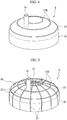
FIG. 2 is a perspective view of an upper cover of the scroll compressor of the first embodiment of the present invention. -
FIG. 3 is a schematic diagram illustrating a resonance mode of a discharge chamber of the scroll compressor of the first embodiment of the present invention. -
FIG. 4 is a perspective view of an upper cover of a scroll compressor of a first modified example of the first embodiment of the present invention. -
FIG. 5 is a perspective view of an upper cover of a scroll compressor of a second modified example of the first embodiment of the present invention. -
FIG. 6 is a perspective view of an upper cover of a scroll compressor of a second embodiment of the present invention. - Hereinafter, a compressor of a first embodiment of the present invention will be described in detail with reference to the drawings. The compressor of this embodiment is a scroll compressor in which a turning scroll performs a turning motion, a compression chamber volume is decreased as a compression chamber formed between the turning scroll and a fixed scroll is moved to a central portion, and thus a compression action is performed. The scroll compressor of this embodiment is used for a refrigeration cycle and a working fluid is a refrigerant.
- As shown in
FIG. 1 , a scroll compressor 1 has anelectric motor 3, arotary shaft 2 rotatably driven about an axis O1 by theelectric motor 3, a compressormain body 4 configured to compress and discharge a refrigerant using rotation of therotary shaft 2, ahousing 5 accommodating therotary shaft 2, theelectric motor 3, and the compressormain body 4, anupper cover 6 closing one end at first side D1 in an axial direction of thehousing 5, and alower cover 7 closing the second side D2 in the axial direction of thehousing 5. - Note that, in the following description, a direction in which the axis O1 of the
rotary shaft 2 extends is an axial direction D. Furthermore, a direction perpendicular to the axis O1 is a radial direction, a side away from the axis O1 in the radial direction is referred to as an outer side in the radial direction, and a side close to the axis O1 in the radial direction is referred to as an inner side in the radial direction. An upper side inFIG. 1 in the axial direction D is referred to as a first side D1 in the axial direction and a lower side inFIG. 1 in the axial direction D is referred to as a second side D2 in the axial direction. - The compressor
main body 4 compresses the refrigerant using rotational energy of therotary shaft 2 and discharges the compressed refrigerant in a high pressure state to an outside thereof. - The compressor
main body 4 has afixed scroll 17 and aturning scroll 18. Adischarge cover 8 is a substantially disc-shaped member that partitions a space inside thehousing 5 in the axial direction D. A discharge chamber 15 (a discharge space) is a space formed by thedischarge cover 8 and theupper cover 6. Thedischarge chamber 15 is the space into which the refrigerant discharged from the compressormain body 4 is introduced. Adischarge port 20 through which the compressed refrigerant flows to thedischarge chamber 15 and adischarge valve 21 configured to prevent reversely flowing of the refrigerant from a high pressure side are provided at a central portion of thedischarge cover 8. - Note that, although the
discharge chamber 15 of this embodiment is formed of theupper cover 6 and thedischarge cover 8, the present invention is not limited thereto. For example, thedischarge chamber 15 may be formed of theupper cover 6 and a surface of thefixed scroll 17 which faces the first side D1 in the axial direction and may be formed by only theupper cover 6. - A suction pipe 9 configured to suction the refrigerant from an outside thereof is provided on the
housing 5. Adischarge pipe 10 configured to discharge the compressed refrigerant inside thedischarge chamber 15 after being compressed by the compressormain body 4 is provided on theupper cover 6. - 4 The
rotary shaft 2 has a cylindrical shape about the axis O1. Therotary shaft 2 is rotatably supported inside thehousing 5 by amain bearing 11 provided at the first side D1 in the axial direction and asub bearing 13 provided at the second side D2 in the axial direction. A main bearingmain body 12 is attached between the main bearing 11 and an outer peripheral surface of therotary shaft 2. A sub bearingmain body 14 is attached between the sub bearing 13 and the outer peripheral surface of therotary shaft 2. - At an end portion of the
rotary shaft 2 at the first side D1 in the axial direction, aneccentric shaft 16 having a columnar shape about aneccentric axis 02 different from the axis O1 is provided at a position which is offset (eccentric) with respect to the axis O1. Theeccentric axis 02 is parallel to the axis O1. Theeccentric shaft 16 has a cylindrical shape which protrudes from an end portion of therotary shaft 2 toward the first side D1 in the axial direction. Therefore, theeccentric shaft 16 revolves about the axis O1 of therotary shaft 2 in a state in which therotary shaft 2 rotates about the axis O1. - The
fixed scroll 17 is a substantially discoid member fixed inside thehousing 5. Theturning scroll 18 faces thefixed scroll 17 from the axial direction D and thus a compression chamber C is formed between both scrolls. - The
fixed scroll 17 is a fixedend plate 25 having a disc shape and afixed wrap 26 standing up in the axial direction D from a surface of the fixedend plate 25 at the second side D2 thereof in the axial direction. The fixedend plate 25 extends along a surface which is substantially perpendicular to the axis O1. Thefixed wrap 26 is a wall body which is spirally formed when viewed from the axial direction D. Thefixed wrap 26 is formed of plate-like members being wound about a center of the fixedend plate 25. Thefixed wrap 26 is preferably constituted to form an involute curve about the axis O1 when viewed from the axial direction D. - An outer
peripheral wall 27 extending in a tubular shape along an outer circumference of the fixedend plate 25 is formed at the outer side of thefixed wrap 26 in the radial direction. Anannular flange part 28 widening outward in the radial direction is provided at an edge of the outerperipheral wall 27 at the second side D2 in the axial direction. Thefixed scroll 17 is fixed to the main bearing 11 using bolts or the like via theflange part 28. A fixedscroll discharge port 29 is formed at a central portion of a spiral of thefixed scroll 17. - The
turning scroll 18 has aturning end plate 23 having a disc shape and a spiral turningwrap 31 provided at a surface of theturning end plate 23 at the first side D1 in the axial direction. The turningwrap 31 is also preferably constituted to form an involute curve about the axis O1. - The turning
wrap 31 and thefixed wrap 26 are disposed to face each other from the axial direction D and to overlap each other in a direction crossing the axis O1. In other words, thefixed wrap 26 is engaged with the turningwrap 31. A predetermined space is formed between the fixedwrap 26 and the turningwrap 31 in such an engaged state. A volume of the space is changed according to the turning of the turningwrap 31. Thus, the refrigerant can be compressed. - A
boss part 30 having a cylindrical shape is formed at a surface of the turningend plate 23 at the second side D2 in the axial direction. A central axis of theboss part 30 is coaxial with theeccentric axis 02. Theeccentric shaft 16 formed on therotary shaft 2 is fit into a space inside theboss part 30 via adry bush 32 from the axial direction D.A turning bearing 33 is attached between thedry bush 32 and theboss part 30. - An Oldham ring 22 configured to restrict rotation of the turning scroll 18 (rotation about the eccentric axis 02) is provided at the
main bearing 11. A protrusion formed on the Oldham ring 22 is fitted into a groove formed in the turningend plate 23 of the turningscroll 18. Athrust bearing 24 is provided at the inner side of the Oldham ring 22 in the radial direction when viewed from the Oldham ring 22. Thethrust bearing 24 supports a load in the axial direction D due to the turningscroll 18. - The
upper cover 6 of this embodiment will be described. - As shown in
Fig. 2 , theupper cover 6 has an upper covermain body 34 forming the discharge chamber 15 (refer toFig. 1 ) and reinforcing parts 37 (ribs) provided on anouter surface 34a of the upper covermain body 34. The upper covermain body 34 has a circular shape when viewed from the axial direction D and forms part of thedischarge chamber 15. - The upper cover
main body 34 has acylindrical part 35 with a cylindrical shape and adome part 36 configured to block the first side D1 of thecylindrical part 35 in the axial direction. Thedome part 36 has a spherical shape. Thedome part 36 is smoothly connected to thecylindrical part 35. - The plurality of reinforcing
parts 37 extending along theouter surface 34a of the upper covermain body 34 are formed on theouter surface 34a of the upper covermain body 34. The reinforcingparts 37 radially extend from a center T1 of the upper covermain body 34. A center T1 of theupper cover 6 is a point at which the axis O1 crosses theupper cover 6. - The plurality of reinforcing
parts 37 are formed at intervals in a circumferential direction. The plurality of reinforcingparts 37 are preferably formed at equal intervals in the circumferential direction. The reinforcingparts 37 are protrusions protruding from theouter surface 34a of the upper covermain body 34. The reinforcingparts 37 have a function of reinforcing the upper covermain body 34. - Next, a method of designing the scroll compressor 1 of this embodiment will be described.
- The method of designing the scroll compressor 1 has a compressor designing step, a resonance mode measuring step, and a reinforcing part designing step.
- The compressor designing step is a step of designing a scroll compressor on the basis of a required performance or specification or the like. A designer performs selection (design) of an electric motor, design of a scroll, and design of shapes or the like of a housing and an upper cover. Thus, a specification of an electric motor and a shape of a discharge chamber or the like are determined.
- The resonance mode measuring step is a step of performing a simulation on a computer using a compressor model (an analysis model) modeled on the basis of the scroll compressor designed in the compressor designing step and measuring a resonance mode (an acoustic eigenvalue and acoustic characteristics) occurring in a discharge chamber.
- To be specific, first, a compressor model which can be input to the computer is created on the basis of the designed scroll compressor. Subsequently, a behavior of the compressor model is simulated on the computer using analysis software or the like.
- Here, an operation of the scroll compressor 1 will be described. The refrigerant compressed in the compressor main body 4 (a scroll) is periodically discharged from the fixed
scroll discharge port 29 of the fixedscroll 17. The refrigerant that has passed through the fixedscroll discharge port 29 passes through a space between the fixedscroll 17 and thedischarge cover 8. The refrigerant passes through thedischarge port 20 of thedischarge cover 8, enters into thedischarge chamber 15 defined by theupper cover 6, and is discharged through thedischarge pipe 10. - When the refrigerant flows through such a route, pressure pulsation occurs by the periodical discharge of the refrigerant into the discharge chamber 15 (the discharge space) through the
discharge valve 21. If such pressure pulsation coincides with a natural frequency of thedischarge chamber 15, resonance occurs. Theupper cover 6 vibrates due to such resonance. -
FIG. 3 illustrates a resonance mode of thedischarge chamber 15 measured through a simulation. Furthermore, a resonance frequency is specified through the simulation. In the case of the scroll compressor 1 of this embodiment, the resonance frequency is 4 kHz to 5 kHz. - In
FIG. 3 , symbols + indicate positions at which a pressure is high due to resonance, symbols - indicate positions at which the pressure is low due to the resonance, and these positions are antinodes of a resonance mode. - The resonance mode is not limited to a case shown in
FIG. 3 and changes in accordance with a shape or the like of thedischarge chamber 15. For example, intervals of the antinodes of the resonance mode in a circumferential direction change in accordance with a rotational speed or the like of therotary shaft 2. - In the reinforcing part designing step, the reinforcing
parts 37 are designed on theouter surface 34a of the upper covermain body 34 on the basis of positions of the antinodes of the resonance mode measured in the resonance mode measuring step. To be specific, the reinforcingparts 37 are designed to pass through the antinodes of the resonance mode. - According to the above-described embodiments, even when the positions corresponding to the antinodes of the resonance mode at the
upper cover 6 vibrate due to the resonance, the reinforcingparts 37 can suppress vibration of theupper cover 6. In other words, the positions corresponding to the antinodes of the resonance mode are reinforced using the reinforcingparts 37 so that noise due to vibrations can be reduced. - Note that shapes of the reinforcing
parts 37 are not limited to this and may be shapes in which the reinforcingparts 37 are provided on at least one of theouter surface 34a and an inner surface of the upper covermain body 34 and extend along at least one of theouter surface 34a and the inner surface thereof to reinforce the positions corresponding to the antinodes of the resonance mode. - For example, as in reinforcing
parts 37B of a first modified example shown inFIG. 4 , the reinforcingparts 37B may extend in the circumferential direction to pass through the antinodes of the resonance mode. To be specific, the reinforcingparts 37B of the first modified example of this embodiment are a plurality of annular reinforcing parts which are concentrically formed. At least in part of the reinforcingparts 37B are formed to pass through the antinodes of the resonance mode. - According to this modified example, even if the antinodes of the resonance mode are moved in the circumferential direction, vibrations can be minimized.
- Also, as in reinforcing parts of a second modified example shown in
FIG. 5 , reinforcingparts 37 extending in the radial direction and annular reinforcingparts 37B extending in the circumferential direction may be combined. - According to this modified example, rigidity of the upper cover
main body 34 can be further improved. - Also, the above-described embodiments have a constitution in which peripheries of the reinforcing
parts 37 are reinforced by the reinforcingparts 37, but may have a constitution in which sites corresponding to the antinodes of the resonance mode are relatively reinforced compared with other sites by forming concave grooves extending in the radial direction at portions (nodes of the resonance mode) between the neighboring antinodes of the resonance mode. - The
upper cover 6 obtained by integrating the upper covermain body 34 and the reinforcingparts 37 may be manufactured through casting and theupper cover 6 obtained by integrating the upper covermain body 34 and the reinforcingparts 37 may be cut through cutting. - The upper cover
main body 34 and the reinforcingparts 37 may be separately formed and be joined through welding or the like. - The reinforcing
parts 37 are not limited to theouter surface 34a of the upper cover 6 (the surface facing the first side D1 in the axial direction) and may be formed at an inner surface of theupper cover 6. However, since a shape of thedischarge chamber 15 is changed when the reinforcingparts 37 are formed at the inner surface of theupper cover 6, this is not preferable. - Also, positions of the reinforcing
parts 37 may be determined through measurement using an actual device without performing analysis. - Hereinafter, a compressor of a second embodiment of the present invention will be described in detail with reference to the drawings. Note that, in this embodiment, description is provided focusing on differences from the above-described first embodiment and descriptions of the same parts will be omitted.
- An
upper cover 6B of the compressor of this embodiment has a polygonal pyramid shape having a top part T2 protruding toward the first side D1 in the axial direction. In other words, as shown inFIG. 6 , theupper cover 6B may be formed of atubular part 35B of which a cross-sectional shape has a dodecagon shape and a dodecagonal-pyramid-shapeddome part 36B. - In the case of such a shape, a strength of oblique ridges 39 (ridgelines) of the dodecagonal-pyramid-shaped
dome part 36B is higher than a strength of lateral surfaces 40. Thus, positions of theoblique ridges 39 correspond to antinodes of a resonance mode, and therefore, vibrations can be minimized. In other words, theoblique ridges 39 of the dodecagonal-pyramid-shapeddome part 36B are reinforcing parts of this embodiment. Theupper cover 6B with such a shape can be manufactured using sheet metal press processing. - Although the embodiments of the present invention have been described in detail above, various changes can be made without departing from the scope of the present invention.
- For example, the scroll compressor is adopted as the compressor in the above-described embodiments; however, it may be adapted to a compressor including a rotary shaft rotatably driven, a compressor main body configured to periodically compress and discharge a fluid using rotation of a rotary shaft, and a cover having a discharge space, into which the fluid discharged from the compressor main body is introduced. The present invention can also be applied to a swash-plate-type compressor, and a rotary compressor as the compressor.
- While preferred embodiments of the invention have been described and illustrated above, it should be understood that these are exemplary of the invention and are not to be considered as limiting. Additions, omissions, substitutions, and other modifications can be made without departing from the scope of the present invention. Accordingly, the invention is not to be considered as being limited by the foregoing description, and is only limited by the scope of the appended claims.
Claims (6)
- A compressor (1) comprising:a rotary shaft (2) rotatably driven;a compressor main body (4) configured to periodically compress and discharge a fluid using rotation of the rotary shaft (2); anda cover (6) provided with a cover main body (34) having a discharge space into which the fluid discharged from the compressor main body (4) is introduced, and a plurality of reinforcing parts (37) provided on at least one of an outer surface and an inner surface of the cover main body (34) and extending along at least one of the outer surface and the inner surface thereof.
- The compressor (1) according to Claim 1, comprising:an electric motor (3) configured to rotatably drive the rotary shaft (2) about an axis; anda housing (5) having a cylindrical shape along the axis and accommodating the electric motor (3), the rotary shaft (2), and the compressor main body (4),wherein the cover (6) is an upper cover configured to close one end of the housing (5).
- The compressor (1) according to Claim 2, wherein
the housing (5) has a cylindrical shape,
the cover main body (34) has a circular shape when viewed from the axial direction, and
the plurality of reinforcing parts (37) extend radially from a center of the cover main body (34). - The compressor (1) according to Claim 2 or 3, wherein
the plurality of reinforcing parts (37) extend in a circumferential direction with respect to the center of the cover main body (34). - The compressor (1) according to Claim 2, wherein
the cover main body (34) has a polygonal pyramid shape having a top part protruding in the axial direction, and
the plurality of reinforcing parts (37) are oblique ridges of the cover main body (34). - A method of designing a compressor (1) comprising:a compressor designing step of designing the compressor (1) including a compressor main body (4) including a rotary shaft (2) rotatably driven and configured to periodically compress and discharge a fluid using rotation of the rotary shaft (2) and a cover (6) defining a discharge space into which the fluid discharged from the compressor main body (4) is introduced;a resonance mode measuring step of measuring a resonance mode occurring in the discharge space using a compressor model modeled on the basis of the compressor (1) designed in the compressor designing step; anda reinforcing part designing step of designing a plurality of reinforcing parts (37), the plurality of reinforcing parts (37) being provided on at least one of an outer surface and an inner surface of the cover (6) to pass through antinodes of the resonance mode on the basis of the resonance mode measured in the resonance mode measuring step and extending along at least one of the outer surface and the inner surface of the cover (6).
Applications Claiming Priority (1)
| Application Number | Priority Date | Filing Date | Title |
|---|---|---|---|
| JP2016060502A JP6948112B2 (en) | 2016-03-24 | 2016-03-24 | Compressor |
Publications (2)
| Publication Number | Publication Date |
|---|---|
| EP3222852A1 true EP3222852A1 (en) | 2017-09-27 |
| EP3222852B1 EP3222852B1 (en) | 2020-06-10 |
Family
ID=58401462
Family Applications (1)
| Application Number | Title | Priority Date | Filing Date |
|---|---|---|---|
| EP17162259.0A Active EP3222852B1 (en) | 2016-03-24 | 2017-03-22 | Compressor and method of designing compressor |
Country Status (2)
| Country | Link |
|---|---|
| EP (1) | EP3222852B1 (en) |
| JP (1) | JP6948112B2 (en) |
Cited By (2)
| Publication number | Priority date | Publication date | Assignee | Title |
|---|---|---|---|---|
| CN112739911A (en) * | 2018-10-30 | 2021-04-30 | 法雷奥日本株式会社 | Reinforcing structure of electric compressor |
| CN114641615A (en) * | 2019-11-01 | 2022-06-17 | 莱格特普莱特加拿大公司 | Pump noise attenuator and method |
Citations (3)
| Publication number | Priority date | Publication date | Assignee | Title |
|---|---|---|---|---|
| JP2001336484A (en) | 2000-05-26 | 2001-12-07 | Daikin Ind Ltd | Assembly structure of bearing housing and casing and scroll compressor |
| EP2275685A2 (en) * | 2009-06-18 | 2011-01-19 | Kamtec Inc. | Vacuum pump for vehicles |
| KR20150067657A (en) * | 2013-12-10 | 2015-06-18 | 영신정공 주식회사 | ELECTRO VACUUM PUMP to reduce the Noise |
Family Cites Families (5)
| Publication number | Priority date | Publication date | Assignee | Title |
|---|---|---|---|---|
| JPS53123611U (en) * | 1977-03-09 | 1978-10-02 | ||
| JPS5786593A (en) * | 1980-11-19 | 1982-05-29 | Hitachi Ltd | Rotary compressor |
| JPH0792068B2 (en) * | 1987-01-12 | 1995-10-09 | 松下冷機株式会社 | Rotary compressor |
| JP2000291560A (en) * | 1999-04-02 | 2000-10-17 | Matsushita Refrig Co Ltd | Hermetic electrically driven compressor |
| JP2004150322A (en) * | 2002-10-30 | 2004-05-27 | Hitachi Home & Life Solutions Inc | Hermetic compressor and refrigerator using the same |
-
2016
- 2016-03-24 JP JP2016060502A patent/JP6948112B2/en active Active
-
2017
- 2017-03-22 EP EP17162259.0A patent/EP3222852B1/en active Active
Patent Citations (3)
| Publication number | Priority date | Publication date | Assignee | Title |
|---|---|---|---|---|
| JP2001336484A (en) | 2000-05-26 | 2001-12-07 | Daikin Ind Ltd | Assembly structure of bearing housing and casing and scroll compressor |
| EP2275685A2 (en) * | 2009-06-18 | 2011-01-19 | Kamtec Inc. | Vacuum pump for vehicles |
| KR20150067657A (en) * | 2013-12-10 | 2015-06-18 | 영신정공 주식회사 | ELECTRO VACUUM PUMP to reduce the Noise |
Cited By (3)
| Publication number | Priority date | Publication date | Assignee | Title |
|---|---|---|---|---|
| CN112739911A (en) * | 2018-10-30 | 2021-04-30 | 法雷奥日本株式会社 | Reinforcing structure of electric compressor |
| EP3875761A4 (en) * | 2018-10-30 | 2022-08-03 | Valeo Japan Co., Ltd | REINFORCEMENT STRUCTURE FOR ELECTRICALLY DRIVEN COMPRESSOR |
| CN114641615A (en) * | 2019-11-01 | 2022-06-17 | 莱格特普莱特加拿大公司 | Pump noise attenuator and method |
Also Published As
| Publication number | Publication date |
|---|---|
| JP2017172498A (en) | 2017-09-28 |
| EP3222852B1 (en) | 2020-06-10 |
| JP6948112B2 (en) | 2021-10-13 |
Similar Documents
| Publication | Publication Date | Title |
|---|---|---|
| EP3447296A1 (en) | Compressor | |
| US10030657B2 (en) | Electric compressor and method for manufacturing same | |
| CN104334882A (en) | Compressor base plate with ribs for increased oil volume and spacer-free rail mounting structure | |
| US11598336B2 (en) | Method of making a two-piece counterweight for a scroll compressor | |
| JP2011099362A (en) | Scroll fluid machine | |
| EP3222852B1 (en) | Compressor and method of designing compressor | |
| EP3343065A1 (en) | Inertia adjuster and rotary compressor | |
| EP3015710B1 (en) | Compressor | |
| EP1471256B1 (en) | Enclosed type compressor | |
| CN212479578U (en) | scroll compressor | |
| WO2014057602A1 (en) | Compressor | |
| JP6727300B2 (en) | Rotary compressor | |
| EP3315777B1 (en) | Scroll compressor and method for producing scroll compressor | |
| CN107882738B (en) | Compressor with a compressor housing having a plurality of compressor blades | |
| CN111133196A (en) | Cross slip ring and scroll compressor | |
| JP6704751B2 (en) | Scroll compressor | |
| WO2016052325A1 (en) | Compressor | |
| KR100782679B1 (en) | Rotary compressor | |
| KR101708307B1 (en) | Hermetic compressor and manufacturing method thereof | |
| KR101821708B1 (en) | Scroll compressor with split type orbitting scroll | |
| CN103270307A (en) | Scroll compressor with split type fixed scroll | |
| KR101731443B1 (en) | Hermetic compressor | |
| US12553439B2 (en) | Scroll compressor | |
| KR102254667B1 (en) | A rotary compressor and a method for manufacturing the same | |
| EP3604763A1 (en) | Supercharger vibration suppressing method, and supercharger |
Legal Events
| Date | Code | Title | Description |
|---|---|---|---|
| PUAI | Public reference made under article 153(3) epc to a published international application that has entered the european phase |
Free format text: ORIGINAL CODE: 0009012 |
|
| STAA | Information on the status of an ep patent application or granted ep patent |
Free format text: STATUS: THE APPLICATION HAS BEEN PUBLISHED |
|
| AK | Designated contracting states |
Kind code of ref document: A1 Designated state(s): AL AT BE BG CH CY CZ DE DK EE ES FI FR GB GR HR HU IE IS IT LI LT LU LV MC MK MT NL NO PL PT RO RS SE SI SK SM TR |
|
| AX | Request for extension of the european patent |
Extension state: BA ME |
|
| STAA | Information on the status of an ep patent application or granted ep patent |
Free format text: STATUS: REQUEST FOR EXAMINATION WAS MADE |
|
| 17P | Request for examination filed |
Effective date: 20180327 |
|
| RBV | Designated contracting states (corrected) |
Designated state(s): AL AT BE BG CH CY CZ DE DK EE ES FI FR GB GR HR HU IE IS IT LI LT LU LV MC MK MT NL NO PL PT RO RS SE SI SK SM TR |
|
| RIC1 | Information provided on ipc code assigned before grant |
Ipc: F04C 18/12 20060101ALI20191219BHEP Ipc: F04C 18/16 20060101ALI20191219BHEP Ipc: F04C 18/08 20060101ALI20191219BHEP Ipc: F04C 18/02 20060101AFI20191219BHEP Ipc: F04C 18/344 20060101ALI20191219BHEP Ipc: F04C 18/356 20060101ALI20191219BHEP |
|
| GRAP | Despatch of communication of intention to grant a patent |
Free format text: ORIGINAL CODE: EPIDOSNIGR1 |
|
| STAA | Information on the status of an ep patent application or granted ep patent |
Free format text: STATUS: GRANT OF PATENT IS INTENDED |
|
| INTG | Intention to grant announced |
Effective date: 20200302 |
|
| GRAS | Grant fee paid |
Free format text: ORIGINAL CODE: EPIDOSNIGR3 |
|
| GRAA | (expected) grant |
Free format text: ORIGINAL CODE: 0009210 |
|
| STAA | Information on the status of an ep patent application or granted ep patent |
Free format text: STATUS: THE PATENT HAS BEEN GRANTED |
|
| AK | Designated contracting states |
Kind code of ref document: B1 Designated state(s): AL AT BE BG CH CY CZ DE DK EE ES FI FR GB GR HR HU IE IS IT LI LT LU LV MC MK MT NL NO PL PT RO RS SE SI SK SM TR |
|
| REG | Reference to a national code |
Ref country code: GB Ref legal event code: FG4D |
|
| REG | Reference to a national code |
Ref country code: CH Ref legal event code: EP Ref country code: AT Ref legal event code: REF Ref document number: 1279415 Country of ref document: AT Kind code of ref document: T Effective date: 20200615 |
|
| REG | Reference to a national code |
Ref country code: DE Ref legal event code: R096 Ref document number: 602017017868 Country of ref document: DE |
|
| REG | Reference to a national code |
Ref country code: IE Ref legal event code: FG4D |
|
| REG | Reference to a national code |
Ref country code: LT Ref legal event code: MG4D |
|
| PG25 | Lapsed in a contracting state [announced via postgrant information from national office to epo] |
Ref country code: LT Free format text: LAPSE BECAUSE OF FAILURE TO SUBMIT A TRANSLATION OF THE DESCRIPTION OR TO PAY THE FEE WITHIN THE PRESCRIBED TIME-LIMIT Effective date: 20200610 Ref country code: GR Free format text: LAPSE BECAUSE OF FAILURE TO SUBMIT A TRANSLATION OF THE DESCRIPTION OR TO PAY THE FEE WITHIN THE PRESCRIBED TIME-LIMIT Effective date: 20200911 Ref country code: FI Free format text: LAPSE BECAUSE OF FAILURE TO SUBMIT A TRANSLATION OF THE DESCRIPTION OR TO PAY THE FEE WITHIN THE PRESCRIBED TIME-LIMIT Effective date: 20200610 Ref country code: NO Free format text: LAPSE BECAUSE OF FAILURE TO SUBMIT A TRANSLATION OF THE DESCRIPTION OR TO PAY THE FEE WITHIN THE PRESCRIBED TIME-LIMIT Effective date: 20200910 Ref country code: SE Free format text: LAPSE BECAUSE OF FAILURE TO SUBMIT A TRANSLATION OF THE DESCRIPTION OR TO PAY THE FEE WITHIN THE PRESCRIBED TIME-LIMIT Effective date: 20200610 |
|
| REG | Reference to a national code |
Ref country code: NL Ref legal event code: MP Effective date: 20200610 |
|
| PG25 | Lapsed in a contracting state [announced via postgrant information from national office to epo] |
Ref country code: HR Free format text: LAPSE BECAUSE OF FAILURE TO SUBMIT A TRANSLATION OF THE DESCRIPTION OR TO PAY THE FEE WITHIN THE PRESCRIBED TIME-LIMIT Effective date: 20200610 Ref country code: RS Free format text: LAPSE BECAUSE OF FAILURE TO SUBMIT A TRANSLATION OF THE DESCRIPTION OR TO PAY THE FEE WITHIN THE PRESCRIBED TIME-LIMIT Effective date: 20200610 Ref country code: BG Free format text: LAPSE BECAUSE OF FAILURE TO SUBMIT A TRANSLATION OF THE DESCRIPTION OR TO PAY THE FEE WITHIN THE PRESCRIBED TIME-LIMIT Effective date: 20200910 Ref country code: LV Free format text: LAPSE BECAUSE OF FAILURE TO SUBMIT A TRANSLATION OF THE DESCRIPTION OR TO PAY THE FEE WITHIN THE PRESCRIBED TIME-LIMIT Effective date: 20200610 |
|
| REG | Reference to a national code |
Ref country code: AT Ref legal event code: MK05 Ref document number: 1279415 Country of ref document: AT Kind code of ref document: T Effective date: 20200610 |
|
| PG25 | Lapsed in a contracting state [announced via postgrant information from national office to epo] |
Ref country code: AL Free format text: LAPSE BECAUSE OF FAILURE TO SUBMIT A TRANSLATION OF THE DESCRIPTION OR TO PAY THE FEE WITHIN THE PRESCRIBED TIME-LIMIT Effective date: 20200610 Ref country code: NL Free format text: LAPSE BECAUSE OF FAILURE TO SUBMIT A TRANSLATION OF THE DESCRIPTION OR TO PAY THE FEE WITHIN THE PRESCRIBED TIME-LIMIT Effective date: 20200610 |
|
| PG25 | Lapsed in a contracting state [announced via postgrant information from national office to epo] |
Ref country code: PT Free format text: LAPSE BECAUSE OF FAILURE TO SUBMIT A TRANSLATION OF THE DESCRIPTION OR TO PAY THE FEE WITHIN THE PRESCRIBED TIME-LIMIT Effective date: 20201012 Ref country code: RO Free format text: LAPSE BECAUSE OF FAILURE TO SUBMIT A TRANSLATION OF THE DESCRIPTION OR TO PAY THE FEE WITHIN THE PRESCRIBED TIME-LIMIT Effective date: 20200610 Ref country code: ES Free format text: LAPSE BECAUSE OF FAILURE TO SUBMIT A TRANSLATION OF THE DESCRIPTION OR TO PAY THE FEE WITHIN THE PRESCRIBED TIME-LIMIT Effective date: 20200610 Ref country code: CZ Free format text: LAPSE BECAUSE OF FAILURE TO SUBMIT A TRANSLATION OF THE DESCRIPTION OR TO PAY THE FEE WITHIN THE PRESCRIBED TIME-LIMIT Effective date: 20200610 Ref country code: AT Free format text: LAPSE BECAUSE OF FAILURE TO SUBMIT A TRANSLATION OF THE DESCRIPTION OR TO PAY THE FEE WITHIN THE PRESCRIBED TIME-LIMIT Effective date: 20200610 Ref country code: EE Free format text: LAPSE BECAUSE OF FAILURE TO SUBMIT A TRANSLATION OF THE DESCRIPTION OR TO PAY THE FEE WITHIN THE PRESCRIBED TIME-LIMIT Effective date: 20200610 Ref country code: SM Free format text: LAPSE BECAUSE OF FAILURE TO SUBMIT A TRANSLATION OF THE DESCRIPTION OR TO PAY THE FEE WITHIN THE PRESCRIBED TIME-LIMIT Effective date: 20200610 Ref country code: IT Free format text: LAPSE BECAUSE OF FAILURE TO SUBMIT A TRANSLATION OF THE DESCRIPTION OR TO PAY THE FEE WITHIN THE PRESCRIBED TIME-LIMIT Effective date: 20200610 |
|
| PG25 | Lapsed in a contracting state [announced via postgrant information from national office to epo] |
Ref country code: SK Free format text: LAPSE BECAUSE OF FAILURE TO SUBMIT A TRANSLATION OF THE DESCRIPTION OR TO PAY THE FEE WITHIN THE PRESCRIBED TIME-LIMIT Effective date: 20200610 Ref country code: PL Free format text: LAPSE BECAUSE OF FAILURE TO SUBMIT A TRANSLATION OF THE DESCRIPTION OR TO PAY THE FEE WITHIN THE PRESCRIBED TIME-LIMIT Effective date: 20200610 Ref country code: IS Free format text: LAPSE BECAUSE OF FAILURE TO SUBMIT A TRANSLATION OF THE DESCRIPTION OR TO PAY THE FEE WITHIN THE PRESCRIBED TIME-LIMIT Effective date: 20201010 |
|
| REG | Reference to a national code |
Ref country code: DE Ref legal event code: R097 Ref document number: 602017017868 Country of ref document: DE |
|
| PLBE | No opposition filed within time limit |
Free format text: ORIGINAL CODE: 0009261 |
|
| STAA | Information on the status of an ep patent application or granted ep patent |
Free format text: STATUS: NO OPPOSITION FILED WITHIN TIME LIMIT |
|
| PG25 | Lapsed in a contracting state [announced via postgrant information from national office to epo] |
Ref country code: DK Free format text: LAPSE BECAUSE OF FAILURE TO SUBMIT A TRANSLATION OF THE DESCRIPTION OR TO PAY THE FEE WITHIN THE PRESCRIBED TIME-LIMIT Effective date: 20200610 |
|
| 26N | No opposition filed |
Effective date: 20210311 |
|
| PG25 | Lapsed in a contracting state [announced via postgrant information from national office to epo] |
Ref country code: SI Free format text: LAPSE BECAUSE OF FAILURE TO SUBMIT A TRANSLATION OF THE DESCRIPTION OR TO PAY THE FEE WITHIN THE PRESCRIBED TIME-LIMIT Effective date: 20200610 |
|
| PG25 | Lapsed in a contracting state [announced via postgrant information from national office to epo] |
Ref country code: MC Free format text: LAPSE BECAUSE OF FAILURE TO SUBMIT A TRANSLATION OF THE DESCRIPTION OR TO PAY THE FEE WITHIN THE PRESCRIBED TIME-LIMIT Effective date: 20200610 |
|
| REG | Reference to a national code |
Ref country code: CH Ref legal event code: PL |
|
| REG | Reference to a national code |
Ref country code: BE Ref legal event code: MM Effective date: 20210331 |
|
| PG25 | Lapsed in a contracting state [announced via postgrant information from national office to epo] |
Ref country code: IE Free format text: LAPSE BECAUSE OF NON-PAYMENT OF DUE FEES Effective date: 20210322 Ref country code: LU Free format text: LAPSE BECAUSE OF NON-PAYMENT OF DUE FEES Effective date: 20210322 Ref country code: LI Free format text: LAPSE BECAUSE OF NON-PAYMENT OF DUE FEES Effective date: 20210331 Ref country code: CH Free format text: LAPSE BECAUSE OF NON-PAYMENT OF DUE FEES Effective date: 20210331 |
|
| PG25 | Lapsed in a contracting state [announced via postgrant information from national office to epo] |
Ref country code: BE Free format text: LAPSE BECAUSE OF NON-PAYMENT OF DUE FEES Effective date: 20210331 |
|
| REG | Reference to a national code |
Ref country code: DE Ref legal event code: R082 Ref document number: 602017017868 Country of ref document: DE Representative=s name: CBDL PATENTANWAELTE GBR, DE Ref country code: DE Ref legal event code: R082 Ref document number: 602017017868 Country of ref document: DE Representative=s name: CBDL PATENTANWAELTE EGBR, DE |
|
| PG25 | Lapsed in a contracting state [announced via postgrant information from national office to epo] |
Ref country code: HU Free format text: LAPSE BECAUSE OF FAILURE TO SUBMIT A TRANSLATION OF THE DESCRIPTION OR TO PAY THE FEE WITHIN THE PRESCRIBED TIME-LIMIT; INVALID AB INITIO Effective date: 20170322 |
|
| PG25 | Lapsed in a contracting state [announced via postgrant information from national office to epo] |
Ref country code: CY Free format text: LAPSE BECAUSE OF FAILURE TO SUBMIT A TRANSLATION OF THE DESCRIPTION OR TO PAY THE FEE WITHIN THE PRESCRIBED TIME-LIMIT Effective date: 20200610 |
|
| PG25 | Lapsed in a contracting state [announced via postgrant information from national office to epo] |
Ref country code: MK Free format text: LAPSE BECAUSE OF FAILURE TO SUBMIT A TRANSLATION OF THE DESCRIPTION OR TO PAY THE FEE WITHIN THE PRESCRIBED TIME-LIMIT Effective date: 20200610 |
|
| PG25 | Lapsed in a contracting state [announced via postgrant information from national office to epo] |
Ref country code: TR Free format text: LAPSE BECAUSE OF FAILURE TO SUBMIT A TRANSLATION OF THE DESCRIPTION OR TO PAY THE FEE WITHIN THE PRESCRIBED TIME-LIMIT Effective date: 20200610 |
|
| PG25 | Lapsed in a contracting state [announced via postgrant information from national office to epo] |
Ref country code: MT Free format text: LAPSE BECAUSE OF FAILURE TO SUBMIT A TRANSLATION OF THE DESCRIPTION OR TO PAY THE FEE WITHIN THE PRESCRIBED TIME-LIMIT Effective date: 20200610 |
|
| PGFP | Annual fee paid to national office [announced via postgrant information from national office to epo] |
Ref country code: GB Payment date: 20260202 Year of fee payment: 10 |
|
| PGFP | Annual fee paid to national office [announced via postgrant information from national office to epo] |
Ref country code: DE Payment date: 20260128 Year of fee payment: 10 |
|
| PGFP | Annual fee paid to national office [announced via postgrant information from national office to epo] |
Ref country code: FR Payment date: 20260209 Year of fee payment: 10 |