EP3222493A1 - Stitchless steering wheel fitted with leather - Google Patents
Stitchless steering wheel fitted with leather Download PDFInfo
- Publication number
- EP3222493A1 EP3222493A1 EP16199312.6A EP16199312A EP3222493A1 EP 3222493 A1 EP3222493 A1 EP 3222493A1 EP 16199312 A EP16199312 A EP 16199312A EP 3222493 A1 EP3222493 A1 EP 3222493A1
- Authority
- EP
- European Patent Office
- Prior art keywords
- bezel
- leather
- rim
- steering wheel
- groove
- Prior art date
- Legal status (The legal status is an assumption and is not a legal conclusion. Google has not performed a legal analysis and makes no representation as to the accuracy of the status listed.)
- Granted
Links
Images


Classifications
-
- B—PERFORMING OPERATIONS; TRANSPORTING
- B62—LAND VEHICLES FOR TRAVELLING OTHERWISE THAN ON RAILS
- B62D—MOTOR VEHICLES; TRAILERS
- B62D1/00—Steering controls, i.e. means for initiating a change of direction of the vehicle
- B62D1/02—Steering controls, i.e. means for initiating a change of direction of the vehicle vehicle-mounted
- B62D1/04—Hand wheels
- B62D1/06—Rims, e.g. with heating means; Rim covers
-
- B—PERFORMING OPERATIONS; TRANSPORTING
- B62—LAND VEHICLES FOR TRAVELLING OTHERWISE THAN ON RAILS
- B62D—MOTOR VEHICLES; TRAILERS
- B62D1/00—Steering controls, i.e. means for initiating a change of direction of the vehicle
- B62D1/02—Steering controls, i.e. means for initiating a change of direction of the vehicle vehicle-mounted
- B62D1/04—Hand wheels
-
- F—MECHANICAL ENGINEERING; LIGHTING; HEATING; WEAPONS; BLASTING
- F16—ENGINEERING ELEMENTS AND UNITS; GENERAL MEASURES FOR PRODUCING AND MAINTAINING EFFECTIVE FUNCTIONING OF MACHINES OR INSTALLATIONS; THERMAL INSULATION IN GENERAL
- F16B—DEVICES FOR FASTENING OR SECURING CONSTRUCTIONAL ELEMENTS OR MACHINE PARTS TOGETHER, e.g. NAILS, BOLTS, CIRCLIPS, CLAMPS, CLIPS OR WEDGES; JOINTS OR JOINTING
- F16B5/00—Joining sheets or plates, e.g. panels, to one another or to strips or bars parallel to them
- F16B5/06—Joining sheets or plates, e.g. panels, to one another or to strips or bars parallel to them by means of clamps or clips
Definitions
- the present invention relates to a stitchless steering wheel fitted with leather. More particularly, to a technology of covering a steering wheel with leather, by fitting the leather into the steering wheel by using rim bezels and the like instead of sewing the leather.
- hand sewing is applied to cover a steering wheel for a vehicle with leather.
- the hand sewing is carried out nearly completely manually when covering the steering wheel with leather.
- the hand sewing process is carried out in the order of operations of testing raw fabric ⁇ cutting ⁇ sewing/punching (punching for connecting and sewing leather) ⁇ attaching a double-sides tape ⁇ cleaning surfaces (removing foreign substances) ⁇ applying adhesives ⁇ attaching leather ⁇ sewing ⁇ supplying hot air (removing wrinkles on the surface) ⁇ completing the covering operation.
- the process of supplying hot air is carried out to forcedly contract the leather in order to remove wrinkles after covering the steering wheel with the leather, but because of damage to a leather surface caused by a high temperature, problems such as deterioration in durability condition, discoloration of leather, and peeling off of leather occur.
- One steering wheel typically has 400 to 450 stitches, and a cost required for sewing leather is about 24% of an overall price of manufacturing the steering wheel.
- Some automakers sometimes use a method of fitting leather (stitchless) instead of hand sewing in order to solve the problems with the hand sewing, but because of the following problems, the method are rarely used.
- the leather is matched with a PU material with low hardness, which causes a collapse at an edge portion, such that a leather matching portion is separated due to contraction of the leather after the process of supplying hot air and the process of conditioning durability/heat-resistance, and as a result, a defect of an external appearance of the leather matching portion occurs.
- Various aspects of the present invention are directed to providing a stitchless steering wheel fitted with leather, in which a new leather fitting manner is implemented in which a first rim bezel for supporting a grip body and an edge portion of a leather matching portion and a second rim bezel having a leather fixing wedge are coupled by hooks , such that it is possible to solve a problem of a defect of an external appearance of the leather matching portion caused by PU collapse as well as a problem of leather peeling, and to improve fixing force of a leather fitting portion.
- a stitchless steering wheel fitted with leather which is formed by covering a grip body with leather may include a first rim bezel mounted in a wheel groove of the grip body, and including a bezel groove to receive end portions of the leather, and a second rim bezel fastened in the bezel groove of the first rim bezel and fixing the end portions of the leather received in the bezel groove.
- the first rim bezel and the second rim bezel may be fastened to each other through coupling of first hooks formed on wall surfaces of the bezel groove of the first rim bezel and second hooks formed at a lower end portion of the second rim bezel.
- Flanges having an arc-shaped cross section to support portions adjacent to the end portions of the leather, are formed around an upper end portion of the first rim bezel.
- the flanges of the first rim bezel may be divided into a plurality of flange sections by a plurality of cut-away portions which is disposed at predetermined intervals along a rim circumference.
- An adhesive for attaching the end portions of the leather may be applied onto wall surfaces of the bezel groove of the first rim bezel.
- the first rim bezel may be mounted onto the grip body through a plurality of pins.
- a plurality of pierced portions may be formed in the first rim bezel along a rim circumference so as to be disposed at predetermined intervals.
- a leather fixing wedge fixing one surface of the leather which abuts an outer circumferential surface of the second rim bezel in a state in which the second rim bezel is fastened in the bezel groove, may be formed around the outer circumferential surface of the second rim bezel.
- the stitchless steering wheel fitted with leather provided in various embodiments of the present invention has the following advantages.
- a cycle time of a process of covering the steering wheel with the leather may be shortened by about 39%, thereby reducing material costs.
- external appearance marketability may be improved by applying the rim bezels, and external appearance marketability may be improved with various surface treatment processes (painting/plating) on the rim bezels.
- vehicle or “vehicular” or other similar terms as used herein is inclusive of motor vehicles in general such as passenger automobiles including sports utility vehicles (SUV), buses, trucks, various commercial vehicles, watercraft including a variety of boats and ships, aircraft, and the like, and includes hybrid vehicles, electric vehicles, plug-in hybrid electric vehicles, hydrogen-powered vehicles and other alternative fuel vehicles (e.g., fuel derived from resources other than petroleum).
- a hybrid vehicle is a vehicle that has two or more sources of power, for example, both gasoline-powered and electric-powered vehicles.
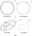
- FIG. 1 is a schematic view illustrating components of a stitchless steering wheel fitted with leather according to various embodiments of the present invention
- FIG. 2 is a schematic view illustrating features of a first rim bezel among the components of the stitchless steering wheel fitted with leather according to various embodiments of the present invention
- FIG. 3 is a schematic view illustrating features of a second rim bezel among the components of the stitchless steering wheel fitted with leather according to various embodiments of the present invention.
- the stitchless steering wheel fitted with leather includes a grip body 10 that is a main body of the steering wheel.
- the grip body 10 is formed in the form of a rim structure having an approximately circular cross section, and a wheel groove 12, which is continuously formed along a length of a circular rim and has a predetermined depth, is provided in a rear surface of the grip body 10 (see FIG. 4 ).
- a first rim bezel 14, which will be described below, may be mounted by being fitted into the wheel groove 12.
- a rim portion of the grip body 10 may be completely covered by leather 11.
- the stitchless steering wheel fitted with leather includes the first rim bezel 14 as a means that receives end portions of the leather 11 and holds the leather 11 so as to support an edge of a leather matching portion (and a solve a problem of a defect of an external appearance caused by PU collapse).
- a bezel groove 13 which is continuously formed along the length of the circular rim and has a predetermined depth, is provided in the first rim bezel 14, and a second rim bezel 15, which will be described below, and the end portions of the leather 11 may be mounted by being fitted into the bezel groove 13.
- Flanges 22a and 22b each of which has an arc-shaped cross section and serves to support a portion of the leather 11, that is, a portion adjacent to the end portion of the leather 11 which is inserted into the bezel groove 13, are formed around an upper end portion of the first rim bezel 14.
- the flanges 22a and 22b are formed to extend in an arc shape inward and outward from both edges of the bezel groove 13 of the first rim bezel 14, respectively.
- the flanges 22a and 22b may be divided into a plurality of flange sections by a plurality of cut-away portions 18 which is disposed at predetermined intervals along a rim circumference, and a plurality of pierced portions 20, for example, a plurality of pierced portions 20 formed by partially cutting a bottom and a wall of the first rim bezel 14 is formed and disposed at predetermined intervals along the rim circumference in the first rim bezel 14.
- an overall weight of the first rim bezel 14 may be reduced, and particularly, the first rim bezel 14 may have elastic characteristics so that the first rim bezel 14 may be slightly bent.
- the insertion operation and the mounting operation may be more easily carried out because of the flexibility of the first rim bezel 14.
- first wedge-shaped hooks 16 are formed on inner wall surfaces of the bezel groove 13 of the first rim bezel 14, respectively, so as to face each other or to be in a staggered arrangement, and the first hooks 16 and second hooks 17 formed on the second rim bezel 15 may be caught by each other, and as a result, it is possible to prevent the second rim bezel 15 from being separated from the bezel groove 13.
- a groove which has a depth and a width corresponding to a thickness and an area of each of the flanges 22a and 22b formed on the first rim bezel 14, is formed in the grip body 10, and the flanges 22a and 22b of the first rim bezel 14 are inserted and seated into the groove of the grip body 10, such that an outer surface of the grip body 10 may be flush with outer surfaces of the flanges 22a and 22b when the first rim bezel 14 is mounted, and a smooth surface without grooves or bumps may be ensured when the grip body is covered by the leather.
- An adhesive may be applied onto the wall surfaces of the bezel groove 13 formed in the first rim bezel 14, and as a result, the end portions of the leather 11, which are received and inserted into the bezel groove 13, may be fixedly attached to the wall surfaces of the bezel groove 13 by using the adhesive.
- the first rim bezel 14 may be mounted by fastening the flanges 22a and 22b to the grip body 10 through a plurality of pins 19 in a state in which the first rim bezel 14 is fitted into the wheel groove 12 in the grip body 10.
- the flanges 22a and 22b of the first rim bezel 14 support edge portions of the leather matching portion (i.e., bent portions of the leather at a boundary between the end portions of the leather inserted into the bezel groove and the remaining portions of the leather which are exposed to the outside of the bezel groove), and as a result, it is possible to solve a problem of a defect of an external appearance of the leather matching portion caused by PU collapse.
- edge portions of the leather matching portion i.e., bent portions of the leather at a boundary between the end portions of the leather inserted into the bezel groove and the remaining portions of the leather which are exposed to the outside of the bezel groove
- the stitchless steering wheel fitted with leather includes the second rim bezel 15 as a means for fixing the end portions of the leather 11 which are received in the bezel groove 13 of the first rim bezel 14.
- the second rim bezel 15 has a circular band shape, and is mounted by being inserted and fastened into the bezel groove 13 formed in the first rim bezel 14.
- the second wedge-shaped hooks 17 are formed on a lower end portion of the second rim bezel 15, and as a result, when the second rim bezel 15 is mounted in the bezel groove 13 of the first rim bezel 14, the second hooks 17 may be fastened by being caught by the first hooks 16 formed in the first rim bezel 14.
- the second rim bezel 15 may be kept stably mounted in the bezel groove 13 of the first rim bezel 14.
- leather fixing wedge 21 which has a protruding band shape, is formed around an outer circumferential surface of the second rim bezel 15, and the leather fixing wedge 21 serves to press one surface of the leather 11 which abuts on the outer circumferential surface of the second rim bezel 15 in a state in which the second rim bezel 15 is fastened into the bezel groove 13, and as a result, it is possible to increase fixing force at the portions where the leather is fitted.
- the leather fixing wedge 21 may be formed in the form of one or more rows of bands, for example, two rows of bands which are continuously formed around the outer circumferential surface of the second rim bezel 15.
- FIG. 5 is an enlarged cross-sectional view illustrating a coupling structure among the components of the stitchless steering wheel fitted with leather according to various embodiments of the present invention.
- FIG. 5 a structure is shown in which the end portions of the leather 11, which covers the grip body 10, are fixed by using the first rim bezel 14 and the second rim bezel 15.
- the first rim bezel 14 is mounted in the wheel groove 12 formed in the grip body 10.
- the first rim bezel 14 is coupled to the grip body 10 by inserting the first rim bezel 14 into the wheel groove 12 and fastening the pins 19 to the flanges 22a and 22b tightly attached onto the outer circumferential surface of the grip body 10.
- an adhesive such as glue or epoxy is applied onto the wall surfaces of the bezel groove 13 of the first rim bezel 14.
- the grip body 10 is covered by the leather 11, and then both end portions in a width direction of the leather 11 are inserted into the bezel groove 13 of the first rim bezel 14 and attached onto the wall surfaces of the bezel groove 13.
- the second rim bezel 15 is inserted into the bezel groove 13 to which the end portions of the leather 11 are attached, and the second hooks 17 formed at the lower end portion of the second rim bezel 15 are fastened to the first hooks 16 formed in the first rim bezel 14, such that the end portions of the leather are fixedly mounted by the second rim bezel 15 while both surfaces of the second rim bezel 15 press the end portions of the leather which abut on both surfaces of the second rim bezel 15.
- a thickness of the second rim bezel 15 may be set to be relatively greater than a width between the two end portions of the leather which are attached onto the wall surfaces of the bezel groove 13 of the first rim bezel 14, such that the end portions of the leather may be pressed at the same time when the second rim bezel 15 is mounted.
- the leather fixing wedge 21 is formed on both surfaces of the second rim bezel 15, the leather fixing wedge 21 may be embedded in the end portions of the leather when both surfaces of the second rim bezel 15 press the end portions of the leather, thereby increasing leather fixing force.
- the first rim bezel and the grip body are coupled by the pins (or by hooks, and an adhesive is additionally applied), the end portions of the leather (leather fitting portions) and the first rim bezel are attached by an adhesive, the first rim bezel and the second rim bezel are coupled by the hooks, and the end portions of the leather are fixed by the wedge of the second rim bezel.
- the problem of the related art such as a defect of an external appearance of the leather matching portion caused by PU collapse and the problem of leather peeling.
- the second rim bezel it is possible to solve the problem of the related art such as leather peeling occurring during a process of supplying hot air and under a condition of heat-resistance and durability.
Landscapes
- Engineering & Computer Science (AREA)
- Mechanical Engineering (AREA)
- Chemical & Material Sciences (AREA)
- Combustion & Propulsion (AREA)
- Transportation (AREA)
- General Engineering & Computer Science (AREA)
- Steering Controls (AREA)
- Snaps, Bayonet Connections, Set Pins, And Snap Rings (AREA)
Abstract
Description
- The present application claims priority to
Korean Patent Application No. 10-2016-0035763, filed March 25, 2016 - The present invention relates to a stitchless steering wheel fitted with leather. More particularly, to a technology of covering a steering wheel with leather, by fitting the leather into the steering wheel by using rim bezels and the like instead of sewing the leather.
- In general, hand sewing is applied to cover a steering wheel for a vehicle with leather.
- The hand sewing is carried out nearly completely manually when covering the steering wheel with leather.
- As an example, the hand sewing process is carried out in the order of operations of testing raw fabric → cutting → sewing/punching (punching for connecting and sewing leather) → attaching a double-sides tape → cleaning surfaces (removing foreign substances) → applying adhesives → attaching leather → sewing → supplying hot air (removing wrinkles on the surface) → completing the covering operation.
- Since hand sewing is carried out nearly completely manually, there is a problem in that a large amount of cycle time is needed.
- Meanwhile, if stitch intervals are increased to reduce the cycle time required for the sewing, a deterioration of external appearance (i.e., separation of leather, low quality, and the like) occurs. Additionally, grip feeling when a driver holds the steering wheel is degraded because of unevenness of sewed line portions (displeasure when rotating and returning the steering wheel).
- The process of supplying hot air is carried out to forcedly contract the leather in order to remove wrinkles after covering the steering wheel with the leather, but because of damage to a leather surface caused by a high temperature, problems such as deterioration in durability condition, discoloration of leather, and peeling off of leather occur.
- One steering wheel typically has 400 to 450 stitches, and a cost required for sewing leather is about 24% of an overall price of manufacturing the steering wheel.
- Some automakers sometimes use a method of fitting leather (stitchless) instead of hand sewing in order to solve the problems with the hand sewing, but because of the following problems, the method are rarely used.
- First, because of deformation in polyurethane (PU) foam, deterioration in adhesive force of an adhesive, contractile force caused by contraction of leather, and the like, there is a problem in that leather is separated from a leather fitting groove and the leather peels under a high temperature condition.
- Second, during the process of supplying hot air in order to remove wrinkles of leather, the leather peels due to contraction of the leather, and as a result, there is a problem in that a defect rate is increased in the manufacturing step.
- Third, the leather is matched with a PU material with low hardness, which causes a collapse at an edge portion, such that a leather matching portion is separated due to contraction of the leather after the process of supplying hot air and the process of conditioning durability/heat-resistance, and as a result, a defect of an external appearance of the leather matching portion occurs.
- The information disclosed in this Background of the Invention section is only for enhancement of understanding of the general background of the invention and should not be taken as an acknowledgement or any form of suggestion that this information forms the prior art already known to a person skilled in the art.
- Various aspects of the present invention are directed to providing a stitchless steering wheel fitted with leather, in which a new leather fitting manner is implemented in which a first rim bezel for supporting a grip body and an edge portion of a leather matching portion and a second rim bezel having a leather fixing wedge are coupled by hooks , such that it is possible to solve a problem of a defect of an external appearance of the leather matching portion caused by PU collapse as well as a problem of leather peeling, and to improve fixing force of a leather fitting portion.
- According to various aspects of the present invention, a stitchless steering wheel fitted with leather, which is formed by covering a grip body with leather may include a first rim bezel mounted in a wheel groove of the grip body, and including a bezel groove to receive end portions of the leather, and a second rim bezel fastened in the bezel groove of the first rim bezel and fixing the end portions of the leather received in the bezel groove.
- The first rim bezel and the second rim bezel may be fastened to each other through coupling of first hooks formed on wall surfaces of the bezel groove of the first rim bezel and second hooks formed at a lower end portion of the second rim bezel.
- Flanges having an arc-shaped cross section to support portions adjacent to the end portions of the leather, are formed around an upper end portion of the first rim bezel.
- The flanges of the first rim bezel may be divided into a plurality of flange sections by a plurality of cut-away portions which is disposed at predetermined intervals along a rim circumference.
- An adhesive for attaching the end portions of the leather may be applied onto wall surfaces of the bezel groove of the first rim bezel.
- The first rim bezel may be mounted onto the grip body through a plurality of pins.
- A plurality of pierced portions may be formed in the first rim bezel along a rim circumference so as to be disposed at predetermined intervals.
- A leather fixing wedge fixing one surface of the leather which abuts an outer circumferential surface of the second rim bezel in a state in which the second rim bezel is fastened in the bezel groove, may be formed around the outer circumferential surface of the second rim bezel.
- The stitchless steering wheel fitted with leather provided in various embodiments of the present invention has the following advantages.
- First, a cycle time of a process of covering the steering wheel with the leather may be shortened by about 39%, thereby reducing material costs.
- Second, external appearance marketability may be improved by applying the rim bezels, and external appearance marketability may be improved with various surface treatment processes (painting/plating) on the rim bezels.
- Third, a defect rate and complaints caused by leather peeling may be reduced.
- Fourth, it is possible to solve a problem of deterioration in grip feeling caused by surface unevenness of a sewing portion.
- It is understood that the term "vehicle" or "vehicular" or other similar terms as used herein is inclusive of motor vehicles in general such as passenger automobiles including sports utility vehicles (SUV), buses, trucks, various commercial vehicles, watercraft including a variety of boats and ships, aircraft, and the like, and includes hybrid vehicles, electric vehicles, plug-in hybrid electric vehicles, hydrogen-powered vehicles and other alternative fuel vehicles (e.g., fuel derived from resources other than petroleum). As referred to herein, a hybrid vehicle is a vehicle that has two or more sources of power, for example, both gasoline-powered and electric-powered vehicles.
- The methods and apparatuses of the present invention have other features and advantages which will be apparent from or are set forth in more detail in the accompanying drawings, which are incorporated herein, and the following Detailed Description, which together serve to explain certain principles of the present invention.
-
-
FIG. 1 is a schematic view illustrating components of a stitchless steering wheel fitted with leather according to various embodiments of the present invention. -
FIG. 2 is a schematic view illustrating features of a first rim bezel among the components of the stitchless steering wheel fitted with leather according to various embodiments of the present invention. -
FIG. 3 is a schematic view illustrating features of a second rim bezel among the components of stitchless the steering wheel fitted with leather according to various embodiments of the present invention. -
FIG. 4 is a schematic view illustrating a groove formed in a grip body among the components of the stitchless steering wheel fitted with leather according to various embodiments of the present invention. -
FIG. 5 is an enlarged cross-sectional view illustrating a coupling structure among the components of the stitchless steering wheel fitted with leather according to various embodiments of the present invention. - It should be understood that the appended drawings are not necessarily to scale, presenting a somewhat simplified representation of various features illustrative of the basic principles of the invention. The specific design features of the present invention as disclosed herein, including, for example, specific dimensions, orientations, locations, and shapes will be determined in part by the particular intended application and use environment.
- Reference will now be made in detail to various embodiments of the present invention(s), examples of which are illustrated in the accompanying drawings and described below. While the invention(s) will be described in conjunction with exemplary embodiments, it will be understood that the present description is not intended to limit the invention(s) to those exemplary embodiments. On the contrary, the invention(s) is/are intended to cover not only the exemplary embodiments, but also various alternatives, modifications, equivalents and other embodiments, which may be included within the spirit and scope of the invention as defined by the appended claims.
-
FIG. 1 is a schematic view illustrating components of a stitchless steering wheel fitted with leather according to various embodiments of the present invention,FIG. 2 is a schematic view illustrating features of a first rim bezel among the components of the stitchless steering wheel fitted with leather according to various embodiments of the present invention, andFIG. 3 is a schematic view illustrating features of a second rim bezel among the components of the stitchless steering wheel fitted with leather according to various embodiments of the present invention. - As illustrated in
FIGS. 1 to 3 , in the case of a stitchless steering wheel fitted with leather, leather, which covers a grip body, is fixed by two rim bezels, that is, a first rim bezel and a second rim bezel which are mounted on the grip body, and as a result, it is possible to solve a problem of leather peeling as well as a defect of an external appearance of a leather matching portion, and to improve fixing force of a leather fitting portion. - To this end, the stitchless steering wheel fitted with leather includes a
grip body 10 that is a main body of the steering wheel. - The
grip body 10 is formed in the form of a rim structure having an approximately circular cross section, and awheel groove 12, which is continuously formed along a length of a circular rim and has a predetermined depth, is provided in a rear surface of the grip body 10 (seeFIG. 4 ). - A
first rim bezel 14, which will be described below, may be mounted by being fitted into thewheel groove 12. - A rim portion of the
grip body 10 may be completely covered byleather 11. - The stitchless steering wheel fitted with leather includes the
first rim bezel 14 as a means that receives end portions of theleather 11 and holds theleather 11 so as to support an edge of a leather matching portion (and a solve a problem of a defect of an external appearance caused by PU collapse). - A
bezel groove 13 which is continuously formed along the length of the circular rim and has a predetermined depth, is provided in thefirst rim bezel 14, and asecond rim bezel 15, which will be described below, and the end portions of theleather 11 may be mounted by being fitted into thebezel groove 13. -
Flanges leather 11, that is, a portion adjacent to the end portion of theleather 11 which is inserted into thebezel groove 13, are formed around an upper end portion of thefirst rim bezel 14. - For example, the
flanges bezel groove 13 of thefirst rim bezel 14, respectively. - In this case, the
flanges away portions 18 which is disposed at predetermined intervals along a rim circumference, and a plurality of piercedportions 20, for example, a plurality of piercedportions 20 formed by partially cutting a bottom and a wall of thefirst rim bezel 14 is formed and disposed at predetermined intervals along the rim circumference in thefirst rim bezel 14. - Therefore, with the plurality of cut-
away portions 18 and the plurality of piercedportions 20, an overall weight of thefirst rim bezel 14 may be reduced, and particularly, thefirst rim bezel 14 may have elastic characteristics so that thefirst rim bezel 14 may be slightly bent. As a result, when the end portions of the leather are inserted into thebezel groove 13 of thefirst rim bezel 14 or when thesecond rim bezel 15 is mounted in thebezel groove 13 of thefirst rim bezel 14, the insertion operation and the mounting operation may be more easily carried out because of the flexibility of thefirst rim bezel 14. - In particular, first wedge-
shaped hooks 16 are formed on inner wall surfaces of thebezel groove 13 of thefirst rim bezel 14, respectively, so as to face each other or to be in a staggered arrangement, and thefirst hooks 16 andsecond hooks 17 formed on thesecond rim bezel 15 may be caught by each other, and as a result, it is possible to prevent thesecond rim bezel 15 from being separated from thebezel groove 13. - According to various embodiments, a groove, which has a depth and a width corresponding to a thickness and an area of each of the
flanges first rim bezel 14, is formed in thegrip body 10, and theflanges first rim bezel 14 are inserted and seated into the groove of thegrip body 10, such that an outer surface of thegrip body 10 may be flush with outer surfaces of theflanges first rim bezel 14 is mounted, and a smooth surface without grooves or bumps may be ensured when the grip body is covered by the leather. - An adhesive may be applied onto the wall surfaces of the
bezel groove 13 formed in thefirst rim bezel 14, and as a result, the end portions of theleather 11, which are received and inserted into thebezel groove 13, may be fixedly attached to the wall surfaces of thebezel groove 13 by using the adhesive. - The
first rim bezel 14 may be mounted by fastening theflanges grip body 10 through a plurality ofpins 19 in a state in which thefirst rim bezel 14 is fitted into thewheel groove 12 in thegrip body 10. - In particular, the
flanges first rim bezel 14 support edge portions of the leather matching portion (i.e., bent portions of the leather at a boundary between the end portions of the leather inserted into the bezel groove and the remaining portions of the leather which are exposed to the outside of the bezel groove), and as a result, it is possible to solve a problem of a defect of an external appearance of the leather matching portion caused by PU collapse. - The stitchless steering wheel fitted with leather includes the
second rim bezel 15 as a means for fixing the end portions of theleather 11 which are received in thebezel groove 13 of thefirst rim bezel 14. - The
second rim bezel 15 has a circular band shape, and is mounted by being inserted and fastened into thebezel groove 13 formed in thefirst rim bezel 14. - The second wedge-shaped
hooks 17 are formed on a lower end portion of thesecond rim bezel 15, and as a result, when thesecond rim bezel 15 is mounted in thebezel groove 13 of thefirst rim bezel 14, the second hooks 17 may be fastened by being caught by the first hooks 16 formed in thefirst rim bezel 14. - Therefore, with the structure in which the first hooks 16 and the
second hooks 17 are caught by each other, thesecond rim bezel 15 may be kept stably mounted in thebezel groove 13 of thefirst rim bezel 14. -
Leather fixing wedge 21, which has a protruding band shape, is formed around an outer circumferential surface of thesecond rim bezel 15, and theleather fixing wedge 21 serves to press one surface of theleather 11 which abuts on the outer circumferential surface of thesecond rim bezel 15 in a state in which thesecond rim bezel 15 is fastened into thebezel groove 13, and as a result, it is possible to increase fixing force at the portions where the leather is fitted. - Here, the
leather fixing wedge 21 may be formed in the form of one or more rows of bands, for example, two rows of bands which are continuously formed around the outer circumferential surface of thesecond rim bezel 15. -
FIG. 5 is an enlarged cross-sectional view illustrating a coupling structure among the components of the stitchless steering wheel fitted with leather according to various embodiments of the present invention. - As illustrated in
FIG. 5 , a structure is shown in which the end portions of theleather 11, which covers thegrip body 10, are fixed by using thefirst rim bezel 14 and thesecond rim bezel 15. - To this end, the
first rim bezel 14 is mounted in thewheel groove 12 formed in thegrip body 10. - That is, the
first rim bezel 14 is coupled to thegrip body 10 by inserting thefirst rim bezel 14 into thewheel groove 12 and fastening thepins 19 to theflanges grip body 10. - In this case, an adhesive such as glue or epoxy is applied onto the wall surfaces of the
bezel groove 13 of thefirst rim bezel 14. - Next, the
grip body 10 is covered by theleather 11, and then both end portions in a width direction of theleather 11 are inserted into thebezel groove 13 of thefirst rim bezel 14 and attached onto the wall surfaces of thebezel groove 13. - Continually, the
second rim bezel 15 is inserted into thebezel groove 13 to which the end portions of theleather 11 are attached, and the second hooks 17 formed at the lower end portion of thesecond rim bezel 15 are fastened to the first hooks 16 formed in thefirst rim bezel 14, such that the end portions of the leather are fixedly mounted by thesecond rim bezel 15 while both surfaces of thesecond rim bezel 15 press the end portions of the leather which abut on both surfaces of thesecond rim bezel 15. - In this case, a thickness of the
second rim bezel 15 may be set to be relatively greater than a width between the two end portions of the leather which are attached onto the wall surfaces of thebezel groove 13 of thefirst rim bezel 14, such that the end portions of the leather may be pressed at the same time when thesecond rim bezel 15 is mounted. - Since the
leather fixing wedge 21 is formed on both surfaces of thesecond rim bezel 15, theleather fixing wedge 21 may be embedded in the end portions of the leather when both surfaces of thesecond rim bezel 15 press the end portions of the leather, thereby increasing leather fixing force. - As described above, the first rim bezel and the grip body are coupled by the pins (or by hooks, and an adhesive is additionally applied), the end portions of the leather (leather fitting portions) and the first rim bezel are attached by an adhesive, the first rim bezel and the second rim bezel are coupled by the hooks, and the end portions of the leather are fixed by the wedge of the second rim bezel. As a result, it is possible to solve the problem of the related art such as a defect of an external appearance of the leather matching portion caused by PU collapse and the problem of leather peeling. Furthermore, by applying the second rim bezel, it is possible to solve the problem of the related art such as leather peeling occurring during a process of supplying hot air and under a condition of heat-resistance and durability.
- For convenience in explanation and accurate definition in the appended claims, the terms "upper" or "lower", "inner" or "outer" and etc. are used to describe features of the exemplary embodiments with reference to the positions of such features as displayed in the figures.
- The foregoing descriptions of specific exemplary embodiments of the present invention have been presented for purposes of illustration and description. They are not intended to be exhaustive or to limit the invention to the precise forms disclosed, and obviously many modifications and variations are possible in light of the above teachings. The exemplary embodiments were chosen and described in order to explain certain principles of the invention and their practical application, to thereby enable others skilled in the art to make and utilize various exemplary embodiments of the present invention, as well as various alternatives and modifications thereof. It is intended that the scope of the invention be defined by the Claims appended hereto and their equivalents.
Claims (8)
- A stitchless steering wheel fitted with leather, which is formed by covering a grip body with the leather, the steering wheel comprising:a first rim bezel mounted in a wheel groove of the grip body, and including a bezel groove to receive end portions of the leather; anda second rim bezel fastened in the bezel groove of the first rim bezel and fixing the end portions of the leather received in the bezel groove.
- The stitchless steering wheel of claim 1, wherein the first rim bezel and the second rim bezel are fastened to each other through coupling of first hooks formed on wall surfaces of the bezel groove of the first rim bezel and second hooks formed at a lower end portion of the second rim bezel.
- The stitchless steering wheel of claim 1 or 2, wherein flanges having an arc-shaped cross section to support portions adjacent to the end portions of the leather, are formed around an upper end portion of the first rim bezel.
- The stitchless steering wheel of claim 3, wherein the flanges of the first rim bezel are divided into a plurality of flange sections by a plurality of cut-away portions which is disposed at predetermined intervals along a rim circumference.
- The stitchless steering wheel of any one of claims 1 to 4, wherein an adhesive for attaching the end portions of the leather is applied onto wall surfaces of the bezel groove of the first rim bezel.
- The stitchless steering wheel of any one of claims 1 to 5, wherein the first rim bezel is mounted onto the grip body through a plurality of pins.
- The stitchless steering wheel of any one of claims 1 to 6, wherein a plurality of pierced portions is formed in the first rim bezel along a rim circumference to be disposed at predetermined intervals.
- The stitchless steering wheel of any one of claims 1 to 7, wherein a leather fixing wedge fixing one surface of the leather which abuts an outer circumferential surface of the second rim bezel in a state in which the second rim bezel is fastened in the bezel groove, is formed around the outer circumferential surface of the second rim bezel.
Applications Claiming Priority (1)
| Application Number | Priority Date | Filing Date | Title |
|---|---|---|---|
| KR1020160035763A KR101806675B1 (en) | 2016-03-25 | 2016-03-25 | Stitchless leather steering wheel |
Publications (2)
| Publication Number | Publication Date |
|---|---|
| EP3222493A1 true EP3222493A1 (en) | 2017-09-27 |
| EP3222493B1 EP3222493B1 (en) | 2019-09-25 |
Family
ID=57354154
Family Applications (1)
| Application Number | Title | Priority Date | Filing Date |
|---|---|---|---|
| EP16199312.6A Active EP3222493B1 (en) | 2016-03-25 | 2016-11-17 | Stitchless steering wheel fitted with leather |
Country Status (5)
| Country | Link |
|---|---|
| US (1) | US10173712B2 (en) |
| EP (1) | EP3222493B1 (en) |
| JP (1) | JP6786361B2 (en) |
| KR (1) | KR101806675B1 (en) |
| CN (1) | CN107226122B (en) |
Families Citing this family (3)
| Publication number | Priority date | Publication date | Assignee | Title |
|---|---|---|---|---|
| CN113635959B (en) * | 2021-09-18 | 2022-12-30 | 上海临港均胜汽车安全系统有限公司 | Steering wheel |
| KR102550105B1 (en) | 2021-10-05 | 2023-06-30 | 주식회사 코모스 | Jig for attaching pad to steering whhel and method for attaching pad to steering wheel using the same |
| JP2024013113A (en) * | 2022-07-19 | 2024-01-31 | 豊田合成株式会社 | How to wrap a steering wheel in leather |
Citations (7)
| Publication number | Priority date | Publication date | Assignee | Title |
|---|---|---|---|---|
| GB1398685A (en) * | 1972-03-23 | 1975-06-25 | Evanford Ltd | Steering wheel having a covered rim |
| US4581954A (en) * | 1983-06-24 | 1986-04-15 | Toyoda Gosei Co., Ltd. | Steering wheel cover assembly |
| US6079292A (en) * | 1996-05-01 | 2000-06-27 | Breed Automotive Technologies, Inc. | Method and apparatus for leather wrapping of a steering wheel |
| DE10328988A1 (en) * | 2003-06-27 | 2005-01-27 | Bayerische Motoren Werke Ag | Steering wheel for motor vehicles has outer wheel rim with non-slip surface and insert ring of wood |
| EP1777113A2 (en) * | 2005-10-24 | 2007-04-25 | Key Safety Systems, Inc. | Decorative member for a vehicle component |
| EP2511153A1 (en) * | 2011-04-06 | 2012-10-17 | Autoliv Development AB | A Steering Wheel |
| DE102011112134A1 (en) * | 2011-09-01 | 2013-03-07 | Audi Ag | Arrangement for disguising a component, component and motor vehicle |
Family Cites Families (23)
| Publication number | Priority date | Publication date | Assignee | Title |
|---|---|---|---|---|
| US3802291A (en) * | 1972-10-31 | 1974-04-09 | Sheller Globe Corp | Soft steering wheel rim |
| JPS62191576U (en) * | 1986-05-28 | 1987-12-05 | ||
| JPH04163277A (en) | 1990-10-25 | 1992-06-08 | Toyoda Gosei Co Ltd | Leather-wound steering wheel |
| JPH04163276A (en) * | 1990-10-27 | 1992-06-08 | Toyoda Gosei Co Ltd | Leather-wound steering wheel |
| DE19717412C1 (en) * | 1997-04-25 | 1998-07-16 | Daimler Benz Ag | Steering wheel trim |
| JP2000053000A (en) * | 1998-08-05 | 2000-02-22 | Midori Anzen Co Ltd | Leather-coated steering wheel and shift knob |
| DE20013706U1 (en) * | 2000-08-09 | 2000-12-21 | TRW Automotive Safety Systems GmbH & Co. KG, 63743 Aschaffenburg | Steering wheel with decorative element |
| DE20017288U1 (en) * | 2000-10-09 | 2001-02-22 | TRW Automotive Safety Systems GmbH & Co. KG, 63743 Aschaffenburg | Steering wheel with decorative element |
| JP3999598B2 (en) * | 2002-08-07 | 2007-10-31 | 日本プラスト株式会社 | Steering wheel |
| KR100489083B1 (en) * | 2002-10-28 | 2005-05-12 | 현대자동차주식회사 | steering wheel and method of vehicle |
| CN2712761Y (en) * | 2004-05-08 | 2005-07-27 | 萧世辉 | Steering wheel construction with trim and leather wrap |
| DE202004012304U1 (en) * | 2004-08-05 | 2004-12-09 | Trw Automotive Safety Systems Gmbh & Co. Kg | Steering wheel with decorative element |
| JP4692034B2 (en) * | 2005-03-17 | 2011-06-01 | 豊田合成株式会社 | Steering wheel |
| DE102006010155A1 (en) | 2006-02-27 | 2007-09-13 | Takata-Petri Ag | A method of manufacturing a steering wheel and steering wheel made by the method |
| CN101284545B (en) * | 2007-04-10 | 2011-05-25 | Lg化学株式会社 | Steering wheel and method of manufacturing the same |
| US20090007721A1 (en) * | 2007-07-06 | 2009-01-08 | Cortina Roger M | Steering Wheel with Modular Rim Assembly |
| DE102007036802A1 (en) * | 2007-08-02 | 2009-02-05 | Takata-Petri Ag | Process for coating a steering wheel and corresponding steering wheel |
| KR100957294B1 (en) * | 2007-12-15 | 2010-05-12 | 기아자동차주식회사 | Steering wheel and its manufacturing method |
| KR101004915B1 (en) | 2008-12-12 | 2010-12-28 | (주)엘지하우시스 | Steering wheel with decorative cover |
| EP2511154B1 (en) * | 2011-04-06 | 2013-05-29 | Autoliv Development AB | A steering wheel |
| DE102011104994A1 (en) * | 2011-06-22 | 2012-04-19 | Daimler Ag | Steering wheel for motor vehicle, has steering wheel base body and casing, which has films surrounding steering wheel base body outer peripheral |
| KR101307670B1 (en) | 2012-08-08 | 2013-09-12 | 김범수 | Handle cover for vehicle equipped with changeable partial handle cover |
| CN104755354B (en) * | 2012-10-23 | 2019-12-06 | Tk控股公司 | Steering wheel lamp strip |
-
2016
- 2016-03-25 KR KR1020160035763A patent/KR101806675B1/en active Active
- 2016-11-17 EP EP16199312.6A patent/EP3222493B1/en active Active
- 2016-11-21 JP JP2016226078A patent/JP6786361B2/en active Active
- 2016-11-22 US US15/359,350 patent/US10173712B2/en active Active
- 2016-11-30 CN CN201611078901.8A patent/CN107226122B/en active Active
Patent Citations (7)
| Publication number | Priority date | Publication date | Assignee | Title |
|---|---|---|---|---|
| GB1398685A (en) * | 1972-03-23 | 1975-06-25 | Evanford Ltd | Steering wheel having a covered rim |
| US4581954A (en) * | 1983-06-24 | 1986-04-15 | Toyoda Gosei Co., Ltd. | Steering wheel cover assembly |
| US6079292A (en) * | 1996-05-01 | 2000-06-27 | Breed Automotive Technologies, Inc. | Method and apparatus for leather wrapping of a steering wheel |
| DE10328988A1 (en) * | 2003-06-27 | 2005-01-27 | Bayerische Motoren Werke Ag | Steering wheel for motor vehicles has outer wheel rim with non-slip surface and insert ring of wood |
| EP1777113A2 (en) * | 2005-10-24 | 2007-04-25 | Key Safety Systems, Inc. | Decorative member for a vehicle component |
| EP2511153A1 (en) * | 2011-04-06 | 2012-10-17 | Autoliv Development AB | A Steering Wheel |
| DE102011112134A1 (en) * | 2011-09-01 | 2013-03-07 | Audi Ag | Arrangement for disguising a component, component and motor vehicle |
Also Published As
| Publication number | Publication date |
|---|---|
| KR101806675B1 (en) | 2017-12-07 |
| JP6786361B2 (en) | 2020-11-18 |
| KR20170111042A (en) | 2017-10-12 |
| CN107226122A (en) | 2017-10-03 |
| JP2017171274A (en) | 2017-09-28 |
| CN107226122B (en) | 2021-08-10 |
| US10173712B2 (en) | 2019-01-08 |
| US20170274920A1 (en) | 2017-09-28 |
| EP3222493B1 (en) | 2019-09-25 |
Similar Documents
| Publication | Publication Date | Title |
|---|---|---|
| EP3222493B1 (en) | Stitchless steering wheel fitted with leather | |
| US8939489B2 (en) | Motor vehicle interior trim, dashboard and vehicle comprising such a trim | |
| JP6274111B2 (en) | Vehicle window plate with frame and method of assembling vehicle window plate with frame | |
| US20110115127A1 (en) | Method for Producing a Moulded Skin and Mould Arrangement Therefore | |
| US10029625B1 (en) | Bracket support structures for vehicle trim panels, and methods of using the same | |
| KR100999246B1 (en) | Rim of car steering wheel | |
| JP2022185067A (en) | Exterior applique with interchangeable inserts | |
| US20160146353A1 (en) | Boot unit and manufacturing method thereof | |
| US6349987B1 (en) | Composite part for an automobile | |
| EP1777113A2 (en) | Decorative member for a vehicle component | |
| US20070257547A1 (en) | Wheel Rim Assembly and Method for Making the Same | |
| US20090152936A1 (en) | Steering wheel and method of manufacturing the same | |
| US8585122B2 (en) | Vehicle door lining | |
| US8459718B2 (en) | Carpet system | |
| US8398146B2 (en) | Method of joining a backlight cover and headliner clip for a convertible top | |
| GB2560102A (en) | Method for producing a pane unit, and pane unit | |
| US20120292123A1 (en) | Splash cover mounting structure | |
| US20080110292A1 (en) | Steering wheel structure | |
| US8555506B2 (en) | Method of manufacturing a painted plastics material part for the automobile industry, the part including an orifice with a rounded edge, and a part obtained thereby | |
| JP2009214702A (en) | Interior parts structure for automobile | |
| US11897206B2 (en) | Method for attaching emblem to vehicle seat | |
| CN108349442B (en) | Motor vehicle and method of assembly | |
| EP3078566B1 (en) | Steering wheel | |
| JP7158934B2 (en) | Vehicle interior materials and vehicle speaker grills | |
| US20160347265A1 (en) | Cover for vehicle interior lining component |
Legal Events
| Date | Code | Title | Description |
|---|---|---|---|
| PUAI | Public reference made under article 153(3) epc to a published international application that has entered the european phase |
Free format text: ORIGINAL CODE: 0009012 |
|
| STAA | Information on the status of an ep patent application or granted ep patent |
Free format text: STATUS: THE APPLICATION HAS BEEN PUBLISHED |
|
| AK | Designated contracting states |
Kind code of ref document: A1 Designated state(s): AL AT BE BG CH CY CZ DE DK EE ES FI FR GB GR HR HU IE IS IT LI LT LU LV MC MK MT NL NO PL PT RO RS SE SI SK SM TR |
|
| AX | Request for extension of the european patent |
Extension state: BA ME |
|
| STAA | Information on the status of an ep patent application or granted ep patent |
Free format text: STATUS: REQUEST FOR EXAMINATION WAS MADE |
|
| 17P | Request for examination filed |
Effective date: 20180327 |
|
| RBV | Designated contracting states (corrected) |
Designated state(s): AL AT BE BG CH CY CZ DE DK EE ES FI FR GB GR HR HU IE IS IT LI LT LU LV MC MK MT NL NO PL PT RO RS SE SI SK SM TR |
|
| STAA | Information on the status of an ep patent application or granted ep patent |
Free format text: STATUS: EXAMINATION IS IN PROGRESS |
|
| 17Q | First examination report despatched |
Effective date: 20181123 |
|
| GRAP | Despatch of communication of intention to grant a patent |
Free format text: ORIGINAL CODE: EPIDOSNIGR1 |
|
| STAA | Information on the status of an ep patent application or granted ep patent |
Free format text: STATUS: GRANT OF PATENT IS INTENDED |
|
| INTG | Intention to grant announced |
Effective date: 20190417 |
|
| GRAS | Grant fee paid |
Free format text: ORIGINAL CODE: EPIDOSNIGR3 |
|
| GRAA | (expected) grant |
Free format text: ORIGINAL CODE: 0009210 |
|
| STAA | Information on the status of an ep patent application or granted ep patent |
Free format text: STATUS: THE PATENT HAS BEEN GRANTED |
|
| AK | Designated contracting states |
Kind code of ref document: B1 Designated state(s): AL AT BE BG CH CY CZ DE DK EE ES FI FR GB GR HR HU IE IS IT LI LT LU LV MC MK MT NL NO PL PT RO RS SE SI SK SM TR |
|
| REG | Reference to a national code |
Ref country code: GB Ref legal event code: FG4D |
|
| REG | Reference to a national code |
Ref country code: CH Ref legal event code: EP |
|
| REG | Reference to a national code |
Ref country code: AT Ref legal event code: REF Ref document number: 1183550 Country of ref document: AT Kind code of ref document: T Effective date: 20191015 |
|
| REG | Reference to a national code |
Ref country code: IE Ref legal event code: FG4D |
|
| REG | Reference to a national code |
Ref country code: DE Ref legal event code: R096 Ref document number: 602016021162 Country of ref document: DE |
|
| REG | Reference to a national code |
Ref country code: NL Ref legal event code: MP Effective date: 20190925 |
|
| PG25 | Lapsed in a contracting state [announced via postgrant information from national office to epo] |
Ref country code: HR Free format text: LAPSE BECAUSE OF FAILURE TO SUBMIT A TRANSLATION OF THE DESCRIPTION OR TO PAY THE FEE WITHIN THE PRESCRIBED TIME-LIMIT Effective date: 20190925 Ref country code: BG Free format text: LAPSE BECAUSE OF FAILURE TO SUBMIT A TRANSLATION OF THE DESCRIPTION OR TO PAY THE FEE WITHIN THE PRESCRIBED TIME-LIMIT Effective date: 20191225 Ref country code: LT Free format text: LAPSE BECAUSE OF FAILURE TO SUBMIT A TRANSLATION OF THE DESCRIPTION OR TO PAY THE FEE WITHIN THE PRESCRIBED TIME-LIMIT Effective date: 20190925 Ref country code: FI Free format text: LAPSE BECAUSE OF FAILURE TO SUBMIT A TRANSLATION OF THE DESCRIPTION OR TO PAY THE FEE WITHIN THE PRESCRIBED TIME-LIMIT Effective date: 20190925 Ref country code: NO Free format text: LAPSE BECAUSE OF FAILURE TO SUBMIT A TRANSLATION OF THE DESCRIPTION OR TO PAY THE FEE WITHIN THE PRESCRIBED TIME-LIMIT Effective date: 20191225 Ref country code: SE Free format text: LAPSE BECAUSE OF FAILURE TO SUBMIT A TRANSLATION OF THE DESCRIPTION OR TO PAY THE FEE WITHIN THE PRESCRIBED TIME-LIMIT Effective date: 20190925 |
|
| REG | Reference to a national code |
Ref country code: LT Ref legal event code: MG4D |
|
| PG25 | Lapsed in a contracting state [announced via postgrant information from national office to epo] |
Ref country code: RS Free format text: LAPSE BECAUSE OF FAILURE TO SUBMIT A TRANSLATION OF THE DESCRIPTION OR TO PAY THE FEE WITHIN THE PRESCRIBED TIME-LIMIT Effective date: 20190925 Ref country code: LV Free format text: LAPSE BECAUSE OF FAILURE TO SUBMIT A TRANSLATION OF THE DESCRIPTION OR TO PAY THE FEE WITHIN THE PRESCRIBED TIME-LIMIT Effective date: 20190925 Ref country code: GR Free format text: LAPSE BECAUSE OF FAILURE TO SUBMIT A TRANSLATION OF THE DESCRIPTION OR TO PAY THE FEE WITHIN THE PRESCRIBED TIME-LIMIT Effective date: 20191226 |
|
| REG | Reference to a national code |
Ref country code: AT Ref legal event code: MK05 Ref document number: 1183550 Country of ref document: AT Kind code of ref document: T Effective date: 20190925 |
|
| PG25 | Lapsed in a contracting state [announced via postgrant information from national office to epo] |
Ref country code: PL Free format text: LAPSE BECAUSE OF FAILURE TO SUBMIT A TRANSLATION OF THE DESCRIPTION OR TO PAY THE FEE WITHIN THE PRESCRIBED TIME-LIMIT Effective date: 20190925 Ref country code: EE Free format text: LAPSE BECAUSE OF FAILURE TO SUBMIT A TRANSLATION OF THE DESCRIPTION OR TO PAY THE FEE WITHIN THE PRESCRIBED TIME-LIMIT Effective date: 20190925 Ref country code: AT Free format text: LAPSE BECAUSE OF FAILURE TO SUBMIT A TRANSLATION OF THE DESCRIPTION OR TO PAY THE FEE WITHIN THE PRESCRIBED TIME-LIMIT Effective date: 20190925 Ref country code: AL Free format text: LAPSE BECAUSE OF FAILURE TO SUBMIT A TRANSLATION OF THE DESCRIPTION OR TO PAY THE FEE WITHIN THE PRESCRIBED TIME-LIMIT Effective date: 20190925 Ref country code: RO Free format text: LAPSE BECAUSE OF FAILURE TO SUBMIT A TRANSLATION OF THE DESCRIPTION OR TO PAY THE FEE WITHIN THE PRESCRIBED TIME-LIMIT Effective date: 20190925 Ref country code: IT Free format text: LAPSE BECAUSE OF FAILURE TO SUBMIT A TRANSLATION OF THE DESCRIPTION OR TO PAY THE FEE WITHIN THE PRESCRIBED TIME-LIMIT Effective date: 20190925 Ref country code: PT Free format text: LAPSE BECAUSE OF FAILURE TO SUBMIT A TRANSLATION OF THE DESCRIPTION OR TO PAY THE FEE WITHIN THE PRESCRIBED TIME-LIMIT Effective date: 20200127 Ref country code: ES Free format text: LAPSE BECAUSE OF FAILURE TO SUBMIT A TRANSLATION OF THE DESCRIPTION OR TO PAY THE FEE WITHIN THE PRESCRIBED TIME-LIMIT Effective date: 20190925 Ref country code: NL Free format text: LAPSE BECAUSE OF FAILURE TO SUBMIT A TRANSLATION OF THE DESCRIPTION OR TO PAY THE FEE WITHIN THE PRESCRIBED TIME-LIMIT Effective date: 20190925 |
|
| PG25 | Lapsed in a contracting state [announced via postgrant information from national office to epo] |
Ref country code: SM Free format text: LAPSE BECAUSE OF FAILURE TO SUBMIT A TRANSLATION OF THE DESCRIPTION OR TO PAY THE FEE WITHIN THE PRESCRIBED TIME-LIMIT Effective date: 20190925 Ref country code: CZ Free format text: LAPSE BECAUSE OF FAILURE TO SUBMIT A TRANSLATION OF THE DESCRIPTION OR TO PAY THE FEE WITHIN THE PRESCRIBED TIME-LIMIT Effective date: 20190925 Ref country code: IS Free format text: LAPSE BECAUSE OF FAILURE TO SUBMIT A TRANSLATION OF THE DESCRIPTION OR TO PAY THE FEE WITHIN THE PRESCRIBED TIME-LIMIT Effective date: 20200224 Ref country code: SK Free format text: LAPSE BECAUSE OF FAILURE TO SUBMIT A TRANSLATION OF THE DESCRIPTION OR TO PAY THE FEE WITHIN THE PRESCRIBED TIME-LIMIT Effective date: 20190925 |
|
| REG | Reference to a national code |
Ref country code: DE Ref legal event code: R097 Ref document number: 602016021162 Country of ref document: DE |
|
| REG | Reference to a national code |
Ref country code: CH Ref legal event code: PL |
|
| PG2D | Information on lapse in contracting state deleted |
Ref country code: IS |
|
| PG25 | Lapsed in a contracting state [announced via postgrant information from national office to epo] |
Ref country code: LU Free format text: LAPSE BECAUSE OF NON-PAYMENT OF DUE FEES Effective date: 20191117 Ref country code: CH Free format text: LAPSE BECAUSE OF NON-PAYMENT OF DUE FEES Effective date: 20191130 Ref country code: LI Free format text: LAPSE BECAUSE OF NON-PAYMENT OF DUE FEES Effective date: 20191130 Ref country code: DK Free format text: LAPSE BECAUSE OF FAILURE TO SUBMIT A TRANSLATION OF THE DESCRIPTION OR TO PAY THE FEE WITHIN THE PRESCRIBED TIME-LIMIT Effective date: 20190925 Ref country code: MC Free format text: LAPSE BECAUSE OF FAILURE TO SUBMIT A TRANSLATION OF THE DESCRIPTION OR TO PAY THE FEE WITHIN THE PRESCRIBED TIME-LIMIT Effective date: 20190925 Ref country code: IS Free format text: LAPSE BECAUSE OF FAILURE TO SUBMIT A TRANSLATION OF THE DESCRIPTION OR TO PAY THE FEE WITHIN THE PRESCRIBED TIME-LIMIT Effective date: 20200126 |
|
| PLBE | No opposition filed within time limit |
Free format text: ORIGINAL CODE: 0009261 |
|
| STAA | Information on the status of an ep patent application or granted ep patent |
Free format text: STATUS: NO OPPOSITION FILED WITHIN TIME LIMIT |
|
| REG | Reference to a national code |
Ref country code: BE Ref legal event code: MM Effective date: 20191130 |
|
| 26N | No opposition filed |
Effective date: 20200626 |
|
| PG25 | Lapsed in a contracting state [announced via postgrant information from national office to epo] |
Ref country code: IE Free format text: LAPSE BECAUSE OF NON-PAYMENT OF DUE FEES Effective date: 20191117 |
|
| PG25 | Lapsed in a contracting state [announced via postgrant information from national office to epo] |
Ref country code: SI Free format text: LAPSE BECAUSE OF FAILURE TO SUBMIT A TRANSLATION OF THE DESCRIPTION OR TO PAY THE FEE WITHIN THE PRESCRIBED TIME-LIMIT Effective date: 20190925 Ref country code: BE Free format text: LAPSE BECAUSE OF NON-PAYMENT OF DUE FEES Effective date: 20191130 |
|
| PG25 | Lapsed in a contracting state [announced via postgrant information from national office to epo] |
Ref country code: CY Free format text: LAPSE BECAUSE OF FAILURE TO SUBMIT A TRANSLATION OF THE DESCRIPTION OR TO PAY THE FEE WITHIN THE PRESCRIBED TIME-LIMIT Effective date: 20190925 |
|
| PG25 | Lapsed in a contracting state [announced via postgrant information from national office to epo] |
Ref country code: MT Free format text: LAPSE BECAUSE OF FAILURE TO SUBMIT A TRANSLATION OF THE DESCRIPTION OR TO PAY THE FEE WITHIN THE PRESCRIBED TIME-LIMIT Effective date: 20190925 Ref country code: HU Free format text: LAPSE BECAUSE OF FAILURE TO SUBMIT A TRANSLATION OF THE DESCRIPTION OR TO PAY THE FEE WITHIN THE PRESCRIBED TIME-LIMIT; INVALID AB INITIO Effective date: 20161117 |
|
| PG25 | Lapsed in a contracting state [announced via postgrant information from national office to epo] |
Ref country code: TR Free format text: LAPSE BECAUSE OF FAILURE TO SUBMIT A TRANSLATION OF THE DESCRIPTION OR TO PAY THE FEE WITHIN THE PRESCRIBED TIME-LIMIT Effective date: 20190925 |
|
| PG25 | Lapsed in a contracting state [announced via postgrant information from national office to epo] |
Ref country code: MK Free format text: LAPSE BECAUSE OF FAILURE TO SUBMIT A TRANSLATION OF THE DESCRIPTION OR TO PAY THE FEE WITHIN THE PRESCRIBED TIME-LIMIT Effective date: 20190925 |
|
| P01 | Opt-out of the competence of the unified patent court (upc) registered |
Effective date: 20230522 |
|
| PGFP | Annual fee paid to national office [announced via postgrant information from national office to epo] |
Ref country code: DE Payment date: 20251020 Year of fee payment: 10 |
|
| PGFP | Annual fee paid to national office [announced via postgrant information from national office to epo] |
Ref country code: GB Payment date: 20251023 Year of fee payment: 10 |
|
| PGFP | Annual fee paid to national office [announced via postgrant information from national office to epo] |
Ref country code: FR Payment date: 20251021 Year of fee payment: 10 |