EP3222240A1 - High frequency treatment tool and high frequency treatment system - Google Patents
High frequency treatment tool and high frequency treatment system Download PDFInfo
- Publication number
- EP3222240A1 EP3222240A1 EP15860661.6A EP15860661A EP3222240A1 EP 3222240 A1 EP3222240 A1 EP 3222240A1 EP 15860661 A EP15860661 A EP 15860661A EP 3222240 A1 EP3222240 A1 EP 3222240A1
- Authority
- EP
- European Patent Office
- Prior art keywords
- sheath
- wire
- loop formation
- cap
- folded
- Prior art date
- Legal status (The legal status is an assumption and is not a legal conclusion. Google has not performed a legal analysis and makes no representation as to the accuracy of the status listed.)
- Withdrawn
Links
- 230000015572 biosynthetic process Effects 0.000 claims abstract description 93
- 230000000007 visual effect Effects 0.000 claims description 5
- 230000005489 elastic deformation Effects 0.000 claims description 4
- 238000002271 resection Methods 0.000 description 82
- 210000001519 tissue Anatomy 0.000 description 49
- 238000000034 method Methods 0.000 description 24
- 238000011161 development Methods 0.000 description 13
- 238000003780 insertion Methods 0.000 description 13
- 230000037431 insertion Effects 0.000 description 13
- 230000004048 modification Effects 0.000 description 12
- 238000012986 modification Methods 0.000 description 12
- 238000012326 endoscopic mucosal resection Methods 0.000 description 6
- 230000003902 lesion Effects 0.000 description 4
- 230000008569 process Effects 0.000 description 4
- 210000002784 stomach Anatomy 0.000 description 4
- 238000005452 bending Methods 0.000 description 3
- 230000000747 cardiac effect Effects 0.000 description 2
- 239000004020 conductor Substances 0.000 description 2
- 206010028980 Neoplasm Diseases 0.000 description 1
- 208000031481 Pathologic Constriction Diseases 0.000 description 1
- 230000009471 action Effects 0.000 description 1
- 238000013459 approach Methods 0.000 description 1
- 238000005219 brazing Methods 0.000 description 1
- 201000011510 cancer Diseases 0.000 description 1
- 230000008859 change Effects 0.000 description 1
- 238000013461 design Methods 0.000 description 1
- 230000009977 dual effect Effects 0.000 description 1
- 230000000694 effects Effects 0.000 description 1
- 238000001125 extrusion Methods 0.000 description 1
- 208000021302 gastroesophageal reflux disease Diseases 0.000 description 1
- 230000006872 improvement Effects 0.000 description 1
- 230000000977 initiatory effect Effects 0.000 description 1
- 210000000111 lower esophageal sphincter Anatomy 0.000 description 1
- 210000004379 membrane Anatomy 0.000 description 1
- 239000012528 membrane Substances 0.000 description 1
- 210000004400 mucous membrane Anatomy 0.000 description 1
- 230000001105 regulatory effect Effects 0.000 description 1
- 239000011347 resin Substances 0.000 description 1
- 229920005989 resin Polymers 0.000 description 1
- 230000004044 response Effects 0.000 description 1
- 230000036262 stenosis Effects 0.000 description 1
- 208000037804 stenosis Diseases 0.000 description 1
- 239000012780 transparent material Substances 0.000 description 1
- 238000003466 welding Methods 0.000 description 1
Images


Classifications
-
- A—HUMAN NECESSITIES
- A61—MEDICAL OR VETERINARY SCIENCE; HYGIENE
- A61B—DIAGNOSIS; SURGERY; IDENTIFICATION
- A61B18/00—Surgical instruments, devices or methods for transferring non-mechanical forms of energy to or from the body
- A61B18/04—Surgical instruments, devices or methods for transferring non-mechanical forms of energy to or from the body by heating
- A61B18/12—Surgical instruments, devices or methods for transferring non-mechanical forms of energy to or from the body by heating by passing a current through the tissue to be heated, e.g. high-frequency current
- A61B18/14—Probes or electrodes therefor
- A61B18/1492—Probes or electrodes therefor having a flexible, catheter-like structure, e.g. for heart ablation
-
- A—HUMAN NECESSITIES
- A61—MEDICAL OR VETERINARY SCIENCE; HYGIENE
- A61B—DIAGNOSIS; SURGERY; IDENTIFICATION
- A61B1/00—Instruments for performing medical examinations of the interior of cavities or tubes of the body by visual or photographical inspection, e.g. endoscopes; Illuminating arrangements therefor
- A61B1/00064—Constructional details of the endoscope body
- A61B1/00071—Insertion part of the endoscope body
- A61B1/0008—Insertion part of the endoscope body characterised by distal tip features
- A61B1/00089—Hoods
-
- A—HUMAN NECESSITIES
- A61—MEDICAL OR VETERINARY SCIENCE; HYGIENE
- A61B—DIAGNOSIS; SURGERY; IDENTIFICATION
- A61B1/00—Instruments for performing medical examinations of the interior of cavities or tubes of the body by visual or photographical inspection, e.g. endoscopes; Illuminating arrangements therefor
- A61B1/00131—Accessories for endoscopes
- A61B1/00133—Drive units for endoscopic tools inserted through or with the endoscope
-
- A—HUMAN NECESSITIES
- A61—MEDICAL OR VETERINARY SCIENCE; HYGIENE
- A61B—DIAGNOSIS; SURGERY; IDENTIFICATION
- A61B1/00—Instruments for performing medical examinations of the interior of cavities or tubes of the body by visual or photographical inspection, e.g. endoscopes; Illuminating arrangements therefor
- A61B1/012—Instruments for performing medical examinations of the interior of cavities or tubes of the body by visual or photographical inspection, e.g. endoscopes; Illuminating arrangements therefor characterised by internal passages or accessories therefor
- A61B1/018—Instruments for performing medical examinations of the interior of cavities or tubes of the body by visual or photographical inspection, e.g. endoscopes; Illuminating arrangements therefor characterised by internal passages or accessories therefor for receiving instruments
-
- A—HUMAN NECESSITIES
- A61—MEDICAL OR VETERINARY SCIENCE; HYGIENE
- A61B—DIAGNOSIS; SURGERY; IDENTIFICATION
- A61B17/00—Surgical instruments, devices or methods
- A61B17/00234—Surgical instruments, devices or methods for minimally invasive surgery
- A61B2017/00238—Type of minimally invasive operation
- A61B2017/00269—Type of minimally invasive operation endoscopic mucosal resection EMR
-
- A—HUMAN NECESSITIES
- A61—MEDICAL OR VETERINARY SCIENCE; HYGIENE
- A61B—DIAGNOSIS; SURGERY; IDENTIFICATION
- A61B17/00—Surgical instruments, devices or methods
- A61B17/00234—Surgical instruments, devices or methods for minimally invasive surgery
- A61B2017/00292—Surgical instruments, devices or methods for minimally invasive surgery mounted on or guided by flexible, e.g. catheter-like, means
- A61B2017/0034—Surgical instruments, devices or methods for minimally invasive surgery mounted on or guided by flexible, e.g. catheter-like, means adapted to be inserted through a working channel of an endoscope
-
- A—HUMAN NECESSITIES
- A61—MEDICAL OR VETERINARY SCIENCE; HYGIENE
- A61B—DIAGNOSIS; SURGERY; IDENTIFICATION
- A61B17/00—Surgical instruments, devices or methods
- A61B2017/00367—Details of actuation of instruments, e.g. relations between pushing buttons, or the like, and activation of the tool, working tip, or the like
-
- A—HUMAN NECESSITIES
- A61—MEDICAL OR VETERINARY SCIENCE; HYGIENE
- A61B—DIAGNOSIS; SURGERY; IDENTIFICATION
- A61B17/00—Surgical instruments, devices or methods
- A61B2017/0042—Surgical instruments, devices or methods with special provisions for gripping
- A61B2017/00438—Surgical instruments, devices or methods with special provisions for gripping connectable to a finger
-
- A—HUMAN NECESSITIES
- A61—MEDICAL OR VETERINARY SCIENCE; HYGIENE
- A61B—DIAGNOSIS; SURGERY; IDENTIFICATION
- A61B17/00—Surgical instruments, devices or methods
- A61B17/30—Surgical pincettes, i.e. surgical tweezers without pivotal connections
- A61B2017/306—Surgical pincettes, i.e. surgical tweezers without pivotal connections holding by means of suction
- A61B2017/308—Surgical pincettes, i.e. surgical tweezers without pivotal connections holding by means of suction with suction cups
-
- A—HUMAN NECESSITIES
- A61—MEDICAL OR VETERINARY SCIENCE; HYGIENE
- A61B—DIAGNOSIS; SURGERY; IDENTIFICATION
- A61B18/00—Surgical instruments, devices or methods for transferring non-mechanical forms of energy to or from the body
- A61B2018/00053—Mechanical features of the instrument of device
- A61B2018/00184—Moving parts
- A61B2018/00196—Moving parts reciprocating lengthwise
-
- A—HUMAN NECESSITIES
- A61—MEDICAL OR VETERINARY SCIENCE; HYGIENE
- A61B—DIAGNOSIS; SURGERY; IDENTIFICATION
- A61B18/00—Surgical instruments, devices or methods for transferring non-mechanical forms of energy to or from the body
- A61B2018/00315—Surgical instruments, devices or methods for transferring non-mechanical forms of energy to or from the body for treatment of particular body parts
- A61B2018/00482—Digestive system
- A61B2018/00494—Stomach, intestines or bowel
-
- A—HUMAN NECESSITIES
- A61—MEDICAL OR VETERINARY SCIENCE; HYGIENE
- A61B—DIAGNOSIS; SURGERY; IDENTIFICATION
- A61B18/00—Surgical instruments, devices or methods for transferring non-mechanical forms of energy to or from the body
- A61B2018/00571—Surgical instruments, devices or methods for transferring non-mechanical forms of energy to or from the body for achieving a particular surgical effect
- A61B2018/00601—Cutting
-
- A—HUMAN NECESSITIES
- A61—MEDICAL OR VETERINARY SCIENCE; HYGIENE
- A61B—DIAGNOSIS; SURGERY; IDENTIFICATION
- A61B18/00—Surgical instruments, devices or methods for transferring non-mechanical forms of energy to or from the body
- A61B2018/00982—Surgical instruments, devices or methods for transferring non-mechanical forms of energy to or from the body combined with or comprising means for visual or photographic inspections inside the body, e.g. endoscopes
-
- A—HUMAN NECESSITIES
- A61—MEDICAL OR VETERINARY SCIENCE; HYGIENE
- A61B—DIAGNOSIS; SURGERY; IDENTIFICATION
- A61B18/00—Surgical instruments, devices or methods for transferring non-mechanical forms of energy to or from the body
- A61B18/04—Surgical instruments, devices or methods for transferring non-mechanical forms of energy to or from the body by heating
- A61B18/12—Surgical instruments, devices or methods for transferring non-mechanical forms of energy to or from the body by heating by passing a current through the tissue to be heated, e.g. high-frequency current
- A61B18/14—Probes or electrodes therefor
- A61B2018/1405—Electrodes having a specific shape
- A61B2018/1407—Loop
-
- A—HUMAN NECESSITIES
- A61—MEDICAL OR VETERINARY SCIENCE; HYGIENE
- A61B—DIAGNOSIS; SURGERY; IDENTIFICATION
- A61B18/00—Surgical instruments, devices or methods for transferring non-mechanical forms of energy to or from the body
- A61B18/04—Surgical instruments, devices or methods for transferring non-mechanical forms of energy to or from the body by heating
- A61B18/12—Surgical instruments, devices or methods for transferring non-mechanical forms of energy to or from the body by heating by passing a current through the tissue to be heated, e.g. high-frequency current
- A61B18/14—Probes or electrodes therefor
- A61B2018/1405—Electrodes having a specific shape
- A61B2018/1407—Loop
- A61B2018/141—Snare
-
- A—HUMAN NECESSITIES
- A61—MEDICAL OR VETERINARY SCIENCE; HYGIENE
- A61B—DIAGNOSIS; SURGERY; IDENTIFICATION
- A61B18/00—Surgical instruments, devices or methods for transferring non-mechanical forms of energy to or from the body
- A61B18/04—Surgical instruments, devices or methods for transferring non-mechanical forms of energy to or from the body by heating
- A61B18/12—Surgical instruments, devices or methods for transferring non-mechanical forms of energy to or from the body by heating by passing a current through the tissue to be heated, e.g. high-frequency current
- A61B18/14—Probes or electrodes therefor
- A61B2018/1405—Electrodes having a specific shape
- A61B2018/144—Wire
-
- A—HUMAN NECESSITIES
- A61—MEDICAL OR VETERINARY SCIENCE; HYGIENE
- A61B—DIAGNOSIS; SURGERY; IDENTIFICATION
- A61B18/00—Surgical instruments, devices or methods for transferring non-mechanical forms of energy to or from the body
- A61B18/04—Surgical instruments, devices or methods for transferring non-mechanical forms of energy to or from the body by heating
- A61B18/12—Surgical instruments, devices or methods for transferring non-mechanical forms of energy to or from the body by heating by passing a current through the tissue to be heated, e.g. high-frequency current
- A61B18/14—Probes or electrodes therefor
- A61B2018/1475—Electrodes retractable in or deployable from a housing
-
- A—HUMAN NECESSITIES
- A61—MEDICAL OR VETERINARY SCIENCE; HYGIENE
- A61B—DIAGNOSIS; SURGERY; IDENTIFICATION
- A61B90/00—Instruments, implements or accessories specially adapted for surgery or diagnosis and not covered by any of the groups A61B1/00 - A61B50/00, e.g. for luxation treatment or for protecting wound edges
- A61B90/03—Automatic limiting or abutting means, e.g. for safety
- A61B2090/033—Abutting means, stops, e.g. abutting on tissue or skin
- A61B2090/034—Abutting means, stops, e.g. abutting on tissue or skin abutting on parts of the device itself
Definitions
- An aspect of the present invention provides a high-frequency treatment tool used along with a cap that is attached to a distal end of an endoscope and the cap has a tubular inner circumferential surface.
- the high-frequency treatment tool includes: a tubular sheath having flexibility; a first wire part disposed along a longitudinal axis of the sheath; a loop formation part that is a wire continuous to a distal portion of the first wire part and enables elastic deformation to be bent in an annular shape when protruding from the distal portion of the sheath; a second wire part disposed along the longitudinal axis of the sheath; a folded part formed by folding a wire, which is configured to be projected from and retracted into a tip of the sheath and is continuous to a distal portion of the second wire part, in a U shape; a connection part disposed between a distal portion of the loop formation part and a proximal portion of the folded part, configured to bend the proximal portion of the folded part
- the folded part and the connection part may protrude from the tip of the sheath in a state in which the stopper is in contact with the contact surface of the positioning member.
- the sheath 12 is an approximately tubular member that has flexibility.
- the sheath 12 is a tube formed of, for instance, a resin.
- the positioning member 14 is in a shape that protrudes from an inner surface of the sheath 12 to an inner side of the sheath 12.
- the positioning member 14 of the present embodiment is a tubular member that has a proximal end face 14a with which a distal end face 17a of the stopper 17 (to be described below) can come into contact and a through-hole part 14b that has an inner diameter to such a degree that the wire 16 (to be described below) moves freely forward and backward and extends in a direction of the central line of the sheath 12.
- the positioning member 14 may not be in tubular shape.
- the wire 16 of the present embodiment can be projected from and retracted into the distal end of the sheath 12 in response to manipulation caused by the operation part 18 (to be described below) (see Fig. 1 ).
- the first connection part 16f is folded in a direction in which the loop formation part 16c is apart from the first proximal portion 16d2 of the folded part 16d. For this reason, the loop formation part 16c is bent in a loop shape such that an interval between wires is greater than an outer diameter of the sheath 12 in a state in which the loop formation part 16c protrudes from the sheath 12.
- the second wire part 16e is a wire-like portion that is disposed in the sheath 12 at a shorter length than the first wire part 16b to regulate the amount of protrusion of the folded part 16d from the sheath 12.
- the distal portion of the second wire part 16e is continuous to the first proximal portion 16d2 of the folded part 16d (to be described below).
- a proximal portion of the second wire part 16e includes the second end 16h of the wire 16.
- the stopper 17 is fixed to the second end 16h of the wire 16. Movement of the stopper 17 toward the distal side is restricted by the positioning member 14.
- the wire passage part 17c is a portion in which a through-hole having such an inner diameter that the wire 16 can move forward and backward therein is formed.
- a cross-sectional shape of the wire passage part 17c which is orthogonal to a central line thereof follows a contour shape of the wire 16 in a cross section orthogonal to a central line of the wire 16.
- the operation part 18 illustrated in Fig. 1 has a main body part 19 fixed to a proximal end of the sheath 12, and a slider part 22 attached to the main body part 19.
- the main body part 19 has a shaft part 20 having a central line on the same axis as the sheath 12, and a finger hooking ring 21 formed at a proximal end of the shaft part 20.
- the finger hooking ring 21 is a ring having an inner diameter large enough for an operator to insert a finger.
- the finger hooking parts 23 has a plurality of rings, each of which has an inner diameter large enough for an operator to insert a finger. The operator inserts his/her fingers into the respective rings of the finger hooking parts 23, and thereby can stably hold the slider part 22.
- the operator passes his/her fingers through the finger hooking ring 21 of the shaft part 20 and the finger hooking parts 23 of the slider part 22, respectively. Thereby, the operator easily enables the slider part 22 to move forward or backward relative to the shaft part 20 along the central line of the shaft part 20 in a proximal or distal direction.
- FIGS. 4 to 6 are views showing the operation of the endoscopic tissue resection device 1 of the present embodiment.
- tissue resection tool 10 of the present embodiment will be described by giving a procedure of an endoscopic mucosal resection (EMR) using a cap (EMRC) that resects mucosal tissue by using a combination of the endoscope 50, the resection tool 10, and the cap 2 by way of example.
- EMR endoscopic mucosal resection
- EMRC cap
- the cap 2 is attached to the distal end of the insertion body 51 of the endoscope 50 first, as illustrated in Fig. 1 . Subsequently, the endoscope 50 is guided to tissue to be resected by a known procedure.
- a counter electrode plate (not shown) connected to a high-frequency power supply as a counter electrode for the loop formation part 16c of the resection tool 10 is attached to the body of a patient.
- a portion of the entire resection tool 10 which protrudes from the distal end of the treatment tool channel 52 of the endoscope 50 is partly located at a position that can be observed by an operator using an endoscope image.
- the operator guides the distal end of the sheath 12 to a predetermined position in the cap 2 with reference to the endoscope image.
- the sheath 12 can be positioned in the cap 2 by advancing/retreating or rotating the entire operation part relative to the treatment tool channel 52.
- the predetermined position of the distal end of the sheath 12 in the cap 2 is a position at which the folded part 16d can come into contact with the loop holding surface 7 when the wire 16 is displaced along the central line of the sheath 12 in the distal direction of the sheath 12.
- a gap required to develop the loop formation part 16c is present between the distal end of the sheath 12 and the loop holding surface 7 of the cap 2.
- a size of the gap between the distal end of the sheath 12 and the loop holding surface 7 of the cap 2 may be adequately adjusted by an operator on the basis of the endoscope image.
- the sheath 12 is held in the cap 2 by the treatment tool channel 52 to take a posture in which the wire 16 can extend toward the loop holding surface 7 when the wire 16 protrudes from the distal end of the sheath 12.
- the slider part 22 illustrated in Fig. 1 is displaced along the central line of the shaft part 20 in the distal direction of the shaft part 20 by the operator, the first end 16a of the wire 16 moves in the distal direction.
- the wire 16 moves along the central line of the sheath 12 from the proximal end toward the distal end of the sheath 12.
- the second end 16h is regulated to be unable to further move in the distal direction in a direction of a longitudinal axis of the sheath 12.
- the folded part 16d is located at a position that is adjacent to the loop holding surface 7 or at a position at which the distal end face 16d1 of the folded part 16d is in contact with the loop holding surface 7.
- the folded part 16d, the loop formation part 16c, and the first connection part 16f protrude from a tip of the sheath 12.
- the amount of protrusion of the loop formation part 16c from the sheath 12 is smaller than the circumferential length of the inner circumferential surface of the distal end of the cap 2 (i.e. the circumferential length of the portion at which the outer diameter of the loop holding surface 7 is greatest).
- the developed loop formation part 16c is, as illustrated in Fig. 5 , disposed on the loop holding surface 7 according to the annular shape of the loop holding surface 7.
- the loop formation part 16c is formed in an annular shape that follows the inner surface of the cap 2, and is held by the loop holder 6.
- an operator forms negative pressure inside the cap 2 using a suction means (not shown) provided for the endoscope 50.
- a suction means (not shown) provided for the endoscope 50.
- the resection target region is pulled into the cap 2.
- the resection target region enters a region in which the loop formation part 16c comes into contact with the loop holding surface 7 to become the annular shape.
- the operator displaces the slider part 22 illustrated in Fig. 1 along the central line of the shaft part 20 in the proximal direction of the shaft part 20. Then, the first end 16a fixed to the slider part 22 is displaced in the proximal direction by the slider part 22. As the first end 16a is displaced in the proximal direction by the slider part 22, the annular region formed by the loop formation part 16c as illustrated in Fig. 6 is reduced, and comes into contact with the resection target region. The resection target region is enclosed by the loop formation part 16c, and the loop formation part 16c comes into contact with the resection target region.
- the tissue resection device 1 of the present embodiment and the endoscope 50 are extracted from the body.
- the loop formation part 16c is fed out of the distal end of the sheath 12 while the second wire part 16e is being fixed in a state in which the folded part 16d is completely exposed from the sheath 12 in the vicinity of the distal end of the sheath 12. For this reason, the loop formation part 16c is adapted to start to be developed just after the loop formation part 16c starts to protrude from the sheath 12.
- the loop formation part 16c Since the loop formation part 16c is held along the loop holding surface 7 in the process of developing the loop formation part 16c, it is unnecessary to bring the loop formation part 16c into contact with the cap 2 for development of the loop formation part 16c, and the wire 16 hardly receive a force by which the wire 16 is bent from the cap 2. For this reason, forming the wire 16 in a proper loop shape is easier than the related art. For example, as the development of the loop formation part 16c is initiated after the position of the sheath 12 is previously determined, when the loop formation part 16c is extruded from the sheath 12, the loop formation part 16c is naturally developed along the loop holding surface 7 in a proper loop shape, and thus the position of the sheath 12 and the position of the wire 16 need not to be adjusted at the same time. For this reason, the tissue resection device 1 of the present embodiment is easily manipulated during the development of the loop formation part 16c, compared to the related art.
- a gastroesophageal reflux disease occurs due to lower esophageal sphincter relaxation in a state in which a position of a gullet stomach joint region 63 and a position of a gullet hiatus 69 nearly coincide with each other, resection of tissue caused by the procedure of the EMRC is performed multiple times in the vicinity of the gullet stomach joint region 63, and a cardiac region 64 is reconstructed by generating cicatricial stenosis at a resected region.
- tissue resection device 1 of the present embodiment can be applied to the EMRC procedure for any tissue.
- FIG. 8 is a view showing a constitution of a modification of the present embodiment.
- Fig. 8 schematically illustrates an example of an endoscope image when an endoscopic tissue resection device of the present modification is used.
- the sheath 12 has a marking 30 that can be checked using an endoscope image.
- the marking 30 is formed on an outer surface of the sheath 12, for instance, by printing or two-color formation.
- a position of the marking 30 on the outer surface of the sheath 12 is set to be within a visual field of the image pickup unit 53(see Fig. 1 ) of the endoscope 50 at a timing at which a distance suitable for initiating the development of the loop formation part 16c is secured between the distal end of the sheath 12 and the loop holding surface 7.
- the marking 30 is continuous on the outer surface of the sheath 12 in a circumferential direction. Alternatively, the marking 30 is disposed at multiple places of the outer surface of the sheath 12 to be able to be on the endoscope image when the sheath 12 is rotated about the central line of the sheath 12 in the treatment tool channel 52 illustrated in Fig. 1 .
- the development of the loop formation part 16c is initiated on the basis of a position of the marking 30, and thereby, like the above embodiment, the loop formation part 16c can be developed in a proper shape in a state in which the wire 16 is in contact with the loop holding surface 7.
- the positioning member 14 described in the first embodiment is fixed to an inner surface of the inner sheath 31 in the present embodiment.
- a operation part 18 is fixed to a proximal end of the inner sheath 31.
- the outer sheath 32 is attached to the inner sheath 31 to freely move forward and backward relative to the inner sheath 31.
- a distal end of the outer sheath 32 can be located at a farther distal side than a distal end of the inner sheath 31 by the forward/backward movement of the outer sheath 32 relative to the inner sheath 31.
- FIG. 10 is a view showing an operation of the endoscopic tissue resection device 1A.
- an operator manipulates a slider part 22 of the operation part 18 like the first embodiment, and thereby the loop formation part 16c protrudes from the distal end of the inner sheath 31.
- a position of the outer sheath 32 is adjusted to the inner sheath 31, and thereby a position at which the development of the loop formation part 16c is initiated can be changed.
- the folded part 16d protrudes from the distal end of the outer sheath 32.
- a position of the inner sheath 31 is fixed, and the outer sheath 32 is pulled to a proximal side.
- the loop formation part 16c can be developed without substantially changing a position of a distal end face 16d1 of the folded part 16d.
- an outer sheath 32 may have the marking 30 disclosed in the modification of the first embodiment.
- the marking 30 disclosed in the modification of the first embodiment may be provided for both the outer sheath 32 and an inner sheath 31.
- Fig. 11 is a cross-sectional view showing an endoscopic tissue resection device of the present embodiment.
- Fig. 12 is a side view showing another constitution example of the endoscopic tissue resection device of the present embodiment.
- a stopper 33 becoming the same as the state in which the stopper 17 is in contact with the positioning member 14 in the first embodiment is fixed to the inside of a sheath 12.
- a wire passage part 33a having through-holes into which a wire 16 is inserted to freely move forward and backward, and a wire fixing part 33b for fixing a second end 16h of the wire 16 are formed at the stopper 33.
- the stopper 33 is formed of a conductor.
- the wire 16 is extruded from the wire passage part 33a, and development of a loop formation part 16c is initiated.
- a direction of each through-hole in the wire passage part 33a formed at the stopper 33 may be properly set to regulate a direction of the loop formation part 16c in a process of developing the loop formation part 16c.
- the wire passage part 33a formed at the stopper 33 may be directed in a direction that is inclined (e.g. orthogonal) with respect to a central line of the sheath 12 as illustrated in Fig. 12 .
- the loop formation part 16c forming a loop shape and the stopper 33 are together in contact with the resection target region, and a high-frequency current is carried. Thereby, the resection target region is resected like the first embodiment.
- the sheath 12 may have the marking 30 (see Fig. 8 ) disclosed in the modification of the first embodiment.
- the second end 16h of the wire 16 disclosed in the third embodiment may extend up to a proximal side of the sheath 12 that freely moves forward and backward relative to the stopper 33 at the wire fixing part 33b and be coupled to the operation part 18. That is, the stopper 33 may have first and second passage parts in which the wire 16 of a U shape freely moves forward and backward.
- another slider part for displacing the second end 16h is provided and manipulated for the operation part.
- the second end 16h and the first end 16a of the wire 16 can be simultaneously displaced in a direction of the central line of the sheath 12, and a position of the folded part 16d relative to the distal end of the sheath 12 can be changed without developing the wire 16.
- the present invention can be used in a medical device for performing the procedure of the EMRC.
Landscapes
- Health & Medical Sciences (AREA)
- Life Sciences & Earth Sciences (AREA)
- Surgery (AREA)
- Engineering & Computer Science (AREA)
- General Health & Medical Sciences (AREA)
- Veterinary Medicine (AREA)
- Public Health (AREA)
- Physics & Mathematics (AREA)
- Nuclear Medicine, Radiotherapy & Molecular Imaging (AREA)
- Animal Behavior & Ethology (AREA)
- Biomedical Technology (AREA)
- Heart & Thoracic Surgery (AREA)
- Medical Informatics (AREA)
- Molecular Biology (AREA)
- Biophysics (AREA)
- Radiology & Medical Imaging (AREA)
- Pathology (AREA)
- Optics & Photonics (AREA)
- Cardiology (AREA)
- Plasma & Fusion (AREA)
- Otolaryngology (AREA)
- Surgical Instruments (AREA)
- Endoscopes (AREA)
Abstract
Description
- The present invention relates to a high-frequency treatment tool and a high-frequency treatment system.
- Priority is claimed on Japanese Patent Application No.
2014-236933, filed on November 21, 2014 - Recently, endoscopic mucosal resection (EMR) has attract attention as means for treating early membrane cancer. As an improvement to EMR, a method of suctioning a lesion portion into a transparent cap mounted on a tip of an endoscope, and resecting the lesion portion using a high-frequency snare formed at the end of the transparent cap (EMR using a cap (EMRC)) is known.
- For example, living body tissue resection devices used to perform a procedure of EMRC are disclosed in
Patent Documents - Japanese Unexamined Patent Application, First Publication No.
2005-27722 - Japanese Unexamined Patent Application, First Publication No.
2008-73317 - In the procedure of EMRC using the device disclosed in
Patent Document 1, a lesion portion suctioned into a transparent cap is a target to be resected, and an incising medical device such as a high-frequency snare is disposed for enclosing this lesion portion. - In the treatment tool disclosed in
Patent Document 2, a snare wire is protruded from a sheath and then provided along the cap, and a loop large enough to surround a target to be resected is formed in the cap in advance. - When the snare wire is developed in the cap, it is necessary to dispose the snare wire in a proper loop shape at a proper scheduled position of incision while both an amount of protrusion of the snare wire from a treatment tool channel of the endoscope and a developed state of a loop-like portion of the snare wire are each adjusted. To be specific, since the loop portion of the snare wire that has already protruded from a tip of the sheath needs to be developed in the cap in a circular shape, work for simultaneously adjusting both an amount of protrusion of the loop-like portion from the tip of the sheath and a position of the tip of the sheath takes place. For this reason, the conventional EMRC requires skill.
- The present invention has been made in view of the above circumstances, and it is an object of the present invention to provide a high-frequency treatment tool in which a procedure of EMRC is easier over the related art.
- An aspect of the present invention provides a high-frequency treatment tool used along with a cap that is attached to a distal end of an endoscope and the cap has a tubular inner circumferential surface. The high-frequency treatment tool includes: a tubular sheath having flexibility; a first wire part disposed along a longitudinal axis of the sheath; a loop formation part that is a wire continuous to a distal portion of the first wire part and enables elastic deformation to be bent in an annular shape when protruding from the distal portion of the sheath; a second wire part disposed along the longitudinal axis of the sheath; a folded part formed by folding a wire, which is configured to be projected from and retracted into a tip of the sheath and is continuous to a distal portion of the second wire part, in a U shape; a connection part disposed between a distal portion of the loop formation part and a proximal portion of the folded part, configured to bend the proximal portion of the folded part in a direction apart from the distal portion of the second wire part, and connected to the distal portion of the loop formation part; an operation part provided at a proximal portion of the first wire part and configured to enable manipulation such that the folded part, the loop formation part, and the connection part protrude from the tip of the sheath; a stopper provided at a proximal portion of the second wire part and configured to have a diameter larger than an outer diameter of the second wire part; and a positioning member having a contact surface set to come into contact with the stopper at a position at which an amount of protrusion at the loop formation part from the sheath along an axis of the loop formation part is shorter than a circumferential length of an inner circumferential surface at a distal end of the cap.
- The folded part and the connection part may protrude from the tip of the sheath in a state in which the stopper is in contact with the contact surface of the positioning member.
- The high-frequency treatment tool of the aspect may further include a second connection part configured to bend the proximal portion of the folded part in a direction apart from the distal end of the first wire part between the distal portion of the second wire part and the proximal portion of the folded part and connect the distal portion of the second wire part and the proximal portion of the folded part.
- An interval between the wires of the folded part may be smaller than an inner diameter of the sheath.
- The stopper may include a fixing part to which a proximal end of the second wire part is fixed, and a passage part into which the first wire part is inserted to move forward and backward. A distal end of the stopper and a proximal end of the positioning member may come into contact with each other, and thereby the positioning member may regulate movement of the second wire part. When a state in which the stopper and the positioning member are spaced from each other is changed to a state in which the stopper and the positioning member are in contact with each other, the outer sheath is capable of moving with respect to the inner sheath such that a distal end of the outer sheath is capable of being disposed close to the folded part.
- The sheath may include an inner sheath in which the positioning member is fixed, and an outer sheath into which the inner sheath is inserted. In a state in which the positioning member regulate movement of the stopper, a distal end of the outer sheath may allow of movement relative to the inner sheath to be able to be disposed close to the folded part.
- The positioning member may include a first passage part into which the first wire part is inserted, and a second passage part into which the second wire part is inserted, and the positioning member may have conductivity and allow a high-frequency current to be carried.
- The sheath may have a marking at a position entering a visual field of the endoscope at a timing at which the folded part is located at a distal end portion of the cap.
- Another aspect of the present invention provides a high-frequency treatment system that includes: a cap attached to a distal end of an endoscope and having a tubular inner circumferential surface; and a high-frequency treatment tool inserted into a channel of the endoscope. The high-frequency treatment tool includes: a tubular sheath having flexibility; a first wire part disposed along a longitudinal axis of the sheath; a loop formation part that is a wire continuous to a distal portion of the first wire part and enables elastic deformation to be bent in an annular shape when protruding from the distal portion of the sheath; a second wire part disposed along the longitudinal axis of the sheath; a folded part formed by folding a wire, which is configured to be projected from and retracted into a tip of the sheath and is continuous to a distal portion of the second wire part, in a U shape; a connection part disposed between a distal portion of the loop formation part and a proximal portion of the folded part, configured to bend the proximal portion of the folded part in a direction apart from the distal portion of the second wire part, and connected to the distal portion of the loop formation part; an operation part provided at a proximal portion of the first wire part and configured to enable manipulation such that the folded part, the loop formation part, and the connection part protrude from the tip of the sheath; a stopper provided at a proximal portion of the second wire part and configured to have a diameter larger than an outer diameter of the second wire part; and a positioning member having a contact surface set to come into contact with the stopper at a position at which an amount of protrusion of the loop formation part from the sheath along an axis of the loop formation part is shorter than a circumferential length of an inner circumferential surface at a distal end of the cap. The cap has a loop holding surface that protrudes from the inner circumferential surface toward a central line of the cap and with which the folded part allows of contact.
- According to the present invention, a procedure of EMRC is easier over the related art.
-
-
Fig. 1 is an overall view showing a state in which an endoscopic tissue resection device of a first embodiment of the present invention is attached to an endoscope. -
Fig. 2 is a partial cross-sectional view showing a resection tool of the endoscopic tissue resection device. -
Fig. 3 is a view for showing an operation of the resection tool. -
Fig. 4 is a view for showing an operation of the endoscopic tissue resection device. -
Fig. 5 is a view for showing an operation of the endoscopic tissue resection device. -
Fig. 6 is a view for showing an operation of the endoscopic tissue resection device. -
Fig. 7 is a schematic view for showing a procedure of EMRC using the endoscopic tissue resection device. -
Fig. 8 is a view showing a constitution of a modification of the first embodiment, and schematically showing an endoscope image when an endoscopic tissue resection device of the modification is used. -
Fig. 9 is a cross-sectional view showing an endoscopic tissue resection device of a second embodiment of the present invention. -
Fig. 10 is a view for showing an operation of the endoscopic tissue resection device. -
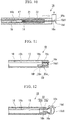
Fig. 11 is a cross-sectional view showing an endoscopic tissue resection device of a third embodiment of the present invention. -
Fig. 12 is a side view showing another constitution example of the endoscopic tissue resection device of the third embodiment. - An endoscopic tissue resection device (a high-frequency treatment system) 1 (hereinafter referred to simply as "
tissue resection device 1") of a first embodiment of the present invention will be described.Fig. 1 is an overall view showing a state in which the endoscopic tissue resection device of the present embodiment is attached to an endoscope.Fig. 2 is a partial cross-sectional view showing a resection tool of the endoscopic tissue resection device.Fig. 3 is a view for showing an action of the resection tool. - As illustrated in
Fig. 1 , thetissue resection device 1 is a medical device has acap 2 and a resection tool (a high-frequency treatment tool) 10 and can be used with anendoscope 50. Thetissue resection device 1 of the present embodiment may be used after it is attached to the knownendoscope 50. The knownendoscope 50 has, for instance, aninsertion body 51 and anoperation body 55. Theinsertion body 51 has atreatment tool channel 52 for guiding theresection tool 10 up to a treatment target region. Animage pickup unit 53 for observing the treatment target region is disposed at a distal end of theinsertion body 51. - The
cap 2 is a member that can be attached to adistal end 51 a of theendoscope 50. At least a part of thecap 2 is preferably transparent at a portion at which it overlaps a visual field of theendoscope 50 such that it does not obstruct the visual field of theendoscope 50. Theentire cap 2 is preferably formed of a transparent material. - The
cap 2 has an approximately tubular shape, and has atube part 3 having openings in opposite ends thereof, and aloop holder 6 disposed at one of the openings of thetube part 3. In the present embodiment, of the two openings formed in thetube part 3, a side (an proximal end side of the cap 2) at which the open end runs along a plane orthogonal to a central line of thecap 2 is anendoscope coupler part 4 that can be attached to theinsertion body 51 of theendoscope 50, and a side (a distal end side of the cap 2) at which the open end runs along a plane inclined with respect to the central line of thecap 2 is acontact part 5 that can be brought into contact with the treatment target region (the resection target region). An oblique angle of thecontact part 5 is set on the basis of an approach angle of theendoscope 50 to the treatment target region. - The
endoscope coupler part 4 is provided for thetube part 3 to be able to be coupled to theendoscope 50 such that theimage pickup unit 53 of theendoscope 50 is disposed inside thetube part 3. For example, a distal end of theinsertion body 51 can be inserted into and fixed to theendoscope coupler part 4. - The
loop holder 6 is an annular portion that is disposed close to thecontact part 5 out of thecap 2. Theloop holder 6 has a distal end of an inner circumferential surface of thetube part 3, and an annular portion that is continuous to the distal end of the inner circumferential surface of thetube part 3 and protrudes from the inner circumferential surface of thetube part 3 toward the central line of thecap 2. Theloop holder 6 has aloop holding surface 7. Theloop holding surface 7 is a surface that is approximately directed to theendoscope coupler part 4 side, and can come into contact with a wire of theresection tool 10. Theloop holding surface 7 of theloop holder 6 of the present embodiment regulates a shape and a size of the opening of the distal portion of thecap 2 when thecap 2 is attached to theendoscope 50. - The
resection tool 10 illustrated inFigs. 1 and2 is a high-frequency treatment tool that can resect a region to be treated in tissue of a living body. Theresection tool 10 is used with thecap 2 attached to the distal end of theendoscope 50. Theresection tool 10 has aninsertion part 11 that is inserted into the body, and anoperation part 18 that is disposed at a proximal end of theinsertion part 11. - As illustrated in
Fig. 2 , theinsertion part 11 has asheath 12 that can be inserted into thetreatment tool channel 52 of theendoscope 50, a positioningmember 14 that is fixed to thesheath 12, a wire (a snare wire) 16 that is disposed inside thesheath 12, and astopper 17 that is disposed inside thesheath 12. - The
sheath 12 is an approximately tubular member that has flexibility. Thesheath 12 is a tube formed of, for instance, a resin. - The positioning
member 14 is in a shape that protrudes from an inner surface of thesheath 12 to an inner side of thesheath 12. The positioningmember 14 of the present embodiment is a tubular member that has aproximal end face 14a with which adistal end face 17a of the stopper 17 (to be described below) can come into contact and a through-hole part 14b that has an inner diameter to such a degree that the wire 16 (to be described below) moves freely forward and backward and extends in a direction of the central line of thesheath 12. The positioningmember 14 may not be in tubular shape. - The
wire 16 is a member of a wire shape that is disposed in thesheath 12 to be projectable and retractable from the distal end of thesheath 12 and is bent in a predetermined shape to come into contact with tissue to be resected and resect the tissue. - The
wire 16 of the present embodiment can be projected from and retracted into the distal end of thesheath 12 in response to manipulation caused by the operation part 18 (to be described below) (seeFig. 1 ). - The
wire 16 is a conductive member to which a high-frequency current is carried from a high-frequency power supply (not shown). Thewire 16 can incise tissue when thewire 16 comes into contact with the tissue in a state in which the high-frequency current is carried to thewire 16. A cross-sectional shape of thewire 16 is not particularly restricted. For example, thewire 16 of the present embodiment is a conductive member whose cross section is in a circular shape. - The
wire 16 has afirst wire part 16b, aloop formation part 16c, a foldedpart 16d, asecond wire part 16e, afirst connection part 16f, and asecond connection part 16g between opposite ends (first and second ends 16a and 16h) thereof. - The
first end 16a of thewire 16 is fixed to aslider part 22 of theoperation part 18. Further, thefirst end 16a of thewire 16 is electrically connected to a connector 24 (to be described below) disposed at theslider part 22. A high-frequency current is carried to thewire 16 via theconnector 24. - The
first wire part 16b is a wire-like portion that extends from theslider part 22 of theoperation part 18 toward a distal side thereof through the inside of thesheath 12 in theentire wire 16. Thefirst wire part 16b extends along a longitudinal axis of thesheath 12. A distal portion of thefirst wire part 16b is continuous to a proximal portion of theloop formation part 16c. Thefirst wire part 16b is inserted into thestopper 17 in thesheath 12 to move freely forward and backward relative to the stopper 17 (to be described below). - The
loop formation part 16c is a wire-like portion that is set between a distal end face 16d1 of the foldedpart 16d and thefirst end 16a of thewire 16 out of theentire wire 16 having a U shape. Theloop formation part 16c is soft enough to be deformed along an inner surface of the cap 2 (seeFig. 1 ). A shape of theloop formation part 16c is set to easily have a loop shape (seeFig. 3 ) surrounding a resection target region in thecap 2. For example, theloop formation part 16c may be formed in a curved shape in a state in which an external force is not applied, and thereby form a predetermined curved shape outside of thesheath 12 to follow the inner surface of thecap 2. By way of example, thefirst connection part 16f is folded in a direction in which theloop formation part 16c is apart from the first proximal portion 16d2 of the foldedpart 16d. For this reason, theloop formation part 16c is bent in a loop shape such that an interval between wires is greater than an outer diameter of thesheath 12 in a state in which theloop formation part 16c protrudes from thesheath 12. - When a
distal end face 17a of thestopper 17 comes into contact with aproximal end face 14a of the positioningmember 14, a length running along an axis of theloop formation part 16c in theloop formation part 16c protruding from thesheath 12 is shorter than a circumferential length of an inner circumferential surface at the distal end of the cap 2 (a circumferential length of a portion at which an outermost diameter of theloop holding surface 7 is great). In a contact state in which thedistal end face 17a of thestopper 17 comes into contact with theproximal end face 14a of the positioningmember 14, only theloop formation part 16c is unreeled from thesheath 12. For this reason, in this contact state, when the distal end face 16d1 of the foldedpart 16d comes into contact with theloop holding surface 7 of thecap 2, the wire can be made to run along theloop holding surface 7 while theloop formation part 16c is being unreeled from thesheath 12. According to this, since there is no trouble of developing thewire 16, which has already protruded from thesheath 12, inside of the cap in an annular shape as in the related art, work for simultaneously adjusting both an amount of protrusion of thewire 16 protruding from thesheath 12 and a position of thesheath 12 is not also required. - In the present embodiment, the
loop formation part 16c is developed inside thecap 2 at a boundary portion between the loop holding surface 7 (seeFig. 1 ) formed at thecap 2 and the inner surface of thecap 2 to follow an oval shape formed by this boundary portion. - The folded
part 16d is a portion which is formed in a shape folded about 180° in a U shape out of theentire wire 16, and at which a curved portion and wires (the first and second proximal portions 16d2 and 16d3) continuous to the curved portion extend in an approximately linear shape. A size of the foldedpart 16d has such a size that the foldedpart 16d can be housed inside thesheath 12. That is, the foldedpart 16d is folded in the U shape such that an interval between the wires (an interval between the aforementioned first and second proximal portions 16d2 and 16d3) in the state in which the foldedpart 16d protrudes from thesheath 12 is smaller than an inner diameter of thesheath 12. When the interval between the first proximal portion 16d2 and the second proximal portion 16d3 is smaller than the inner diameter of thesheath 12, an operator easily checks an amount of protrusion of the foldedpart 16d on an endoscope image. The interval between the aforementioned wires is not necessarily required to be smaller than the inner diameter of thesheath 12. The distal end face 16d1 of the foldedpart 16d is pressed against theloop holding surface 7 that is the distal end at thecap 2. - In the present embodiment, to regulate the loop shape of the
loop formation part 16c, a joint (thefirst connection part 16f) between the second proximal portion 16d3 of the foldedpart 16d and theloop formation part 16c is bent in a direction in which it is apart from the first proximal portion 16d2. A joint (thesecond connection part 16g) between the first proximal portion 16d2 of the foldedpart 16d and a distal portion of thesecond wire part 16e is also bent in a direction in which it is apart from the second proximal portion 16d3. To be specific, in the state in which the foldedpart 16d is housed in thesheath 12, each of thefirst connection part 16f and thesecond connection part 16g has a bending inclination such that it is directed to the outside of thesheath 12 in a radial direction. The bending inclination given to thesecond connection part 16g makes it easy for theloop formation part 16c to be developed inside thecap 2 in an annular shape. The bending inclination at thesecond connection part 16g is not essential. - The
second wire part 16e is a wire-like portion that is disposed in thesheath 12 at a shorter length than thefirst wire part 16b to regulate the amount of protrusion of the foldedpart 16d from thesheath 12. The distal portion of thesecond wire part 16e is continuous to the first proximal portion 16d2 of the foldedpart 16d (to be described below). A proximal portion of thesecond wire part 16e includes thesecond end 16h of thewire 16. Thestopper 17 is fixed to thesecond end 16h of thewire 16. Movement of thestopper 17 toward the distal side is restricted by the positioningmember 14. - The
stopper 17 illustrated inFig. 2 is attached to thewire 16 such that a part of thewire 16 is restricted in movement toward the distal side by the positioningmember 14. - The
stopper 17 has adistal end face 17a that can come into contact with theproximal end face 14a of the positioningmember 14, awire fixing part 17b to which thesecond end 16h of thewire 16 is fixed, and awire passage part 17c into which thefirst wire part 16b serving as an intermediate portion of thewire 16 is inserted. - The
stopper 17 is a tubular member in which two through-holes, central lines of which extend in parallel to each other, are formed. One of the two through-holes is thewire fixing part 17b, and the other through-hole is thewire passage part 17c. - The
wire fixing part 17b is a portion at which thesecond end 16h of thewire 16 is inserted from a distal side toward a proximal side of thestopper 17 and is fixed by a known fixing method. A method of fixing thewire 16 to thewire fixing part 17b is, for instance, brazing or welding. - The
wire passage part 17c is a portion in which a through-hole having such an inner diameter that thewire 16 can move forward and backward therein is formed. A cross-sectional shape of thewire passage part 17c which is orthogonal to a central line thereof follows a contour shape of thewire 16 in a cross section orthogonal to a central line of thewire 16. - The
operation part 18 illustrated inFig. 1 has amain body part 19 fixed to a proximal end of thesheath 12, and aslider part 22 attached to themain body part 19. - The
main body part 19 has ashaft part 20 having a central line on the same axis as thesheath 12, and afinger hooking ring 21 formed at a proximal end of theshaft part 20. - The
shaft part 20 is a member that has an approximate rod shape in which a distal end thereof is fixed to the proximal end of thesheath 12. A space in which thewire 16 is disposed is provided inside theshaft part 20. Theshaft part 20 guides the slider part 22 (to be described below) to displace theslider part 22 along a central line of theshaft part 20. - The
finger hooking ring 21 is a ring having an inner diameter large enough for an operator to insert a finger. - The operator inserts his/her finger into the
finger hooking ring 21, and thereby can stably hold theshaft part 20. - The
slider part 22 is a member that projects and retracts thewire 16 from thesheath 12 to thereby develop theloop formation part 16c or store theloop formation part 16c in thesheath 12. Theslider part 22 is a member that can move relative to theshaft part 20 in a direction of the central line of theshaft part 20, and hasfinger hooking parts 23 and aconnector 24. In the present embodiment, when theslider part 22 moves relative to theshaft part 20 in the direction of the central line of theshaft part 20, theslider part 22 displaces thefirst end 16a of thewire 16 in the direction of the central line of theshaft part 20. - The
finger hooking parts 23 has a plurality of rings, each of which has an inner diameter large enough for an operator to insert a finger. The operator inserts his/her fingers into the respective rings of thefinger hooking parts 23, and thereby can stably hold theslider part 22. - The operator passes his/her fingers through the
finger hooking ring 21 of theshaft part 20 and thefinger hooking parts 23 of theslider part 22, respectively. Thereby, the operator easily enables theslider part 22 to move forward or backward relative to theshaft part 20 along the central line of theshaft part 20 in a proximal or distal direction. - The
connector 24 is a conductor that is fixed to theslider part 22 to carry a high-frequency power source to thewire 16 from a high-frequency power supply (not shown). Thefirst end 16a of thewire 16 is fixed to theconnector 24. - Next, an operation of the
tissue resection device 1 of the present embodiment will be described.Figs. 4 to 6 are views showing the operation of the endoscopictissue resection device 1 of the present embodiment. - Hereinafter, an operation of the
tissue resection tool 10 of the present embodiment will be described by giving a procedure of an endoscopic mucosal resection (EMR) using a cap (EMRC) that resects mucosal tissue by using a combination of theendoscope 50, theresection tool 10, and thecap 2 by way of example. - When the
tissue resection device 1 is used, thecap 2 is attached to the distal end of theinsertion body 51 of theendoscope 50 first, as illustrated inFig. 1 . Subsequently, theendoscope 50 is guided to tissue to be resected by a known procedure. Prior to starting to use thetissue resection device 1, a counter electrode plate (not shown) connected to a high-frequency power supply as a counter electrode for theloop formation part 16c of theresection tool 10 is attached to the body of a patient. - A user of the
tissue resection device 1 brings the distal end of thecap 2 into contact with the tissue to be resected (seeFig. 4 ), and adjusts a position of thecap 2 such that a resection target region is fitted into an opening located at the distal portion of thecap 2. - Subsequently, the user of the
tissue resection device 1 guides theinsertion part 11 of theresection tool 10 to the resection target region through thetreatment tool channel 52 of theendoscope 50, as illustrated inFig. 4 . Thewire 16 is pulled in in a proximal direction of thesheath 12 to such a degree that the foldedpart 16d of thewire 16 is located inside thesheath 12 until theinsertion part 11 of theresection tool 10 is inserted into thetreatment tool channel 52 and protrudes from the distal end of thetreatment tool channel 52. - A portion of the
entire resection tool 10 which protrudes from the distal end of thetreatment tool channel 52 of theendoscope 50 is partly located at a position that can be observed by an operator using an endoscope image. The operator guides the distal end of thesheath 12 to a predetermined position in thecap 2 with reference to the endoscope image. Thesheath 12 can be positioned in thecap 2 by advancing/retreating or rotating the entire operation part relative to thetreatment tool channel 52. The predetermined position of the distal end of thesheath 12 in thecap 2 is a position at which the foldedpart 16d can come into contact with theloop holding surface 7 when thewire 16 is displaced along the central line of thesheath 12 in the distal direction of thesheath 12. - In the present embodiment, the position of the distal end of the
sheath 12 regulates a resection position for the resection target region. That is, a side at which the position of the distal end of thesheath 12 is adjacent to theloop holding surface 7 can more widely resect the resection target region in thecap 2. - A gap required to develop the
loop formation part 16c is present between the distal end of thesheath 12 and theloop holding surface 7 of thecap 2. A size of the gap between the distal end of thesheath 12 and theloop holding surface 7 of thecap 2 may be adequately adjusted by an operator on the basis of the endoscope image. Thesheath 12 is held in thecap 2 by thetreatment tool channel 52 to take a posture in which thewire 16 can extend toward theloop holding surface 7 when thewire 16 protrudes from the distal end of thesheath 12. - Subsequently, as the
slider part 22 illustrated inFig. 1 is displaced along the central line of theshaft part 20 in the distal direction of theshaft part 20 by the operator, thefirst end 16a of thewire 16 moves in the distal direction. Thereby, thewire 16 moves along the central line of thesheath 12 from the proximal end toward the distal end of thesheath 12. - As illustrated in
Fig. 2 , the foldedpart 16d of thewire 16 is pushed in the distal direction by an amount of force transmitted from thefirst end 16a (seeFig. 1 ). Thesecond end 16h of thewire 16 is pulled by the foldedpart 16d and moves in the distal direction of thesheath 12. For this reason, theentire wire 16 moves along the central line of thesheath 12 from the proximal direction to the distal direction of thesheath 12 until thestopper 17 comes into contact with the positioningmember 14. - When the
distal end face 17a of thestopper 17 comes into contact with theproximal end face 14a of the positioningmember 14, thesecond end 16h is regulated to be unable to further move in the distal direction in a direction of a longitudinal axis of thesheath 12. At this point, as illustrated inFig. 4 , the foldedpart 16d is located at a position that is adjacent to theloop holding surface 7 or at a position at which the distal end face 16d1 of the foldedpart 16d is in contact with theloop holding surface 7. Further, in a state in which thedistal end face 17a of thestopper 17 is in contact with theproximal end face 14a of the positioningmember 14, the foldedpart 16d, theloop formation part 16c, and thefirst connection part 16f protrude from a tip of thesheath 12. Further, in the state in which thedistal end face 17a of thestopper 17 is in contact with theproximal end face 14a of the positioningmember 14, the amount of protrusion of theloop formation part 16c from the sheath 12 (the length running along the axis of thewire 16 at theloop formation part 16c) is smaller than the circumferential length of the inner circumferential surface of the distal end of the cap 2 (i.e. the circumferential length of the portion at which the outer diameter of theloop holding surface 7 is greatest). - When the
first end 16a is further displaced in the distal direction by theslider part 22 after thedistal end face 17a of thestopper 17 comes into contact with theproximal end face 14a of the positioningmember 14, thefirst wire part 16b of thewire 16 moves through the inside of thewire passage part 17c of thestopper 17 in the distal direction of thesheath 12. For this reason, a region of theentire wire 16 which is closer to thefirst end 16a than the foldedpart 16d is pushed against a region of theentire wire 16 which is closer to thesecond end 16h than the foldedpart 16d in the distal direction. For this reason, the region of theentire wire 16 which is closer to thefirst end 16a than the foldedpart 16d has, as illustrated inFig. 3 , an approximately arcuate shape at a portion exposed to the outside of thesheath 12. That is, the development of theloop formation part 16c is initiated by a force with which thewire 16 is further pushed out of the state in which thestopper 17 is in contact with the positioningmember 14. In the present embodiment, since theloop formation part 16c protrudes from thesheath 12 and thereby becomes a loop shape in the state in which thesecond end 16h of thewire 16 is fixed, the development of theloop formation part 16c is possible although thewire 16 is not supported by thecap 2. Further, in a process of developing theloop formation part 16c, thewire 16 comes into contact with theloop holding surface 7. Afterwards, with the development of theloop formation part 16c, theloop formation part 16c is held on theloop holding surface 7 in a circumferential direction of the inner circumferential surface of the distal end of thecap 2. - In the conventional snare, it is necessary to adjust a position of the sheath into which the snare is inserted to form a loop at the tip portion of the cap. However, in the present embodiment, it is unnecessary to adjust the position of the
sheath 12 in the process of developing theloop formation part 16c. - Moreover, in the conventional snare, it is necessary to apply a force for pushing out the snare using support caused by the cap and, at this point, the snare is easily detached from the cap. However, in the present embodiment, the
wire 16 is hardly detached from thecap 2. - As the
first end 16a of thewire 16 is pushed out of the opening of the distal end of thesheath 12 by theslider part 22, the developedloop formation part 16c is, as illustrated inFig. 5 , disposed on theloop holding surface 7 according to the annular shape of theloop holding surface 7. Thereby, theloop formation part 16c is formed in an annular shape that follows the inner surface of thecap 2, and is held by theloop holder 6. - Subsequently, an operator forms negative pressure inside the
cap 2 using a suction means (not shown) provided for theendoscope 50. Thereby, as illustrated inFig. 6 , the resection target region is pulled into thecap 2. In thecap 2, as the resection target region is pulled into thecap 2 from the opening of the distal portion of thecap 2, the resection target region enters a region in which theloop formation part 16c comes into contact with theloop holding surface 7 to become the annular shape. - In a state in which the resection target region is pulled into the
cap 2, the operator displaces theslider part 22 illustrated inFig. 1 along the central line of theshaft part 20 in the proximal direction of theshaft part 20. Then, thefirst end 16a fixed to theslider part 22 is displaced in the proximal direction by theslider part 22. As thefirst end 16a is displaced in the proximal direction by theslider part 22, the annular region formed by theloop formation part 16c as illustrated inFig. 6 is reduced, and comes into contact with the resection target region. The resection target region is enclosed by theloop formation part 16c, and theloop formation part 16c comes into contact with the resection target region. In this state, as the high-frequency current is carried to theloop formation part 16c from the high-frequency power supply (not shown), the resection target region is incised. When theslider part 22 is displaced to the proximal side with the high-frequency current carried to theloop formation part 16c, the resection target region is completely excised by theloop formation part 16c. - After the resection target region is excised, the resection target region may be extracted from the body as needed.
- Moreover, after the resection target region is excised, the
tissue resection device 1 of the present embodiment and theendoscope 50 are extracted from the body. - In the conventional EMRC method, when the wire is developed to enclose the resection target region, an amount of extrusion of the wire from the sheath and a position of the sheath need to be adjusted in parallel.
- In the conventional instrument used in the EMRC method, a procedure for the wire being formed in an annular shape to enclose the resection target region at a proper position is complicated.
- In the
resection tool 10 of thetissue resection device 1 of the present embodiment, theloop formation part 16c is fed out of the distal end of thesheath 12 while thesecond wire part 16e is being fixed in a state in which the foldedpart 16d is completely exposed from thesheath 12 in the vicinity of the distal end of thesheath 12. For this reason, theloop formation part 16c is adapted to start to be developed just after theloop formation part 16c starts to protrude from thesheath 12. Since theloop formation part 16c is held along theloop holding surface 7 in the process of developing theloop formation part 16c, it is unnecessary to bring theloop formation part 16c into contact with thecap 2 for development of theloop formation part 16c, and thewire 16 hardly receive a force by which thewire 16 is bent from thecap 2. For this reason, forming thewire 16 in a proper loop shape is easier than the related art. For example, as the development of theloop formation part 16c is initiated after the position of thesheath 12 is previously determined, when theloop formation part 16c is extruded from thesheath 12, theloop formation part 16c is naturally developed along theloop holding surface 7 in a proper loop shape, and thus the position of thesheath 12 and the position of thewire 16 need not to be adjusted at the same time. For this reason, thetissue resection device 1 of the present embodiment is easily manipulated during the development of theloop formation part 16c, compared to the related art. - Next, an example of a concrete procedure using the
tissue resection device 1 of the present embodiment will be described.Fig. 7 is a schematic view showing a procedure of EMRC using the tissue resection device of the present embodiment. - In the present embodiment, as illustrated in
Fig. 7 , a gastroesophageal reflux disease occurs due to lower esophageal sphincter relaxation in a state in which a position of a gullet stomachjoint region 63 and a position of agullet hiatus 69 nearly coincide with each other, resection of tissue caused by the procedure of the EMRC is performed multiple times in the vicinity of the gullet stomachjoint region 63, and acardiac region 64 is reconstructed by generating cicatricial stenosis at a resected region. - The example of the above procedure is merely an example, the
tissue resection device 1 of the present embodiment can be applied to the EMRC procedure for any tissue. - Next, a modification of the present embodiment will be described.
Fig. 8 is a view showing a constitution of a modification of the present embodiment.Fig. 8 schematically illustrates an example of an endoscope image when an endoscopic tissue resection device of the present modification is used. - As illustrated in
Fig. 8 , in the present modification, thesheath 12 has a marking 30 that can be checked using an endoscope image. - The marking 30 is formed on an outer surface of the
sheath 12, for instance, by printing or two-color formation. - A position of the marking 30 on the outer surface of the
sheath 12 is set to be within a visual field of the image pickup unit 53(seeFig. 1 ) of theendoscope 50 at a timing at which a distance suitable for initiating the development of theloop formation part 16c is secured between the distal end of thesheath 12 and theloop holding surface 7. - The marking 30 is continuous on the outer surface of the
sheath 12 in a circumferential direction. Alternatively, the marking 30 is disposed at multiple places of the outer surface of thesheath 12 to be able to be on the endoscope image when thesheath 12 is rotated about the central line of thesheath 12 in thetreatment tool channel 52 illustrated inFig. 1 . - In the present modification, although it cannot be checked by the endoscope image whether the folded
part 16d protrudes from the distal end of thesheath 12, the development of theloop formation part 16c is initiated on the basis of a position of the marking 30, and thereby, like the above embodiment, theloop formation part 16c can be developed in a proper shape in a state in which thewire 16 is in contact with theloop holding surface 7. - Next, a second embodiment of the present invention will be described. In each of the following embodiments, the same components as in the first embodiment are given reference signs shown in the first embodiment, and description repeated with that of the first embodiment will be omitted.
Fig. 9 is a cross-sectional view showing an endoscopic tissue resection device of the present embodiment. - The endoscopic
tissue resection device 1 A of the present embodiment is different in that, in place of thesheath 12 described in the above embodiment, it has asheath 12A of a dual pipe structure due to aninner sheath 31 and anouter sheath 32. - The positioning
member 14 described in the first embodiment is fixed to an inner surface of theinner sheath 31 in the present embodiment. Aoperation part 18 is fixed to a proximal end of theinner sheath 31. - The
outer sheath 32 is attached to theinner sheath 31 to freely move forward and backward relative to theinner sheath 31. A distal end of theouter sheath 32 can be located at a farther distal side than a distal end of theinner sheath 31 by the forward/backward movement of theouter sheath 32 relative to theinner sheath 31. - Next, an operation of the endoscopic
tissue resection device 1A of the present embodiment will be described.Fig. 10 is a view showing an operation of the endoscopictissue resection device 1A. - As illustrated in
Figs. 9 and10 , an operator manipulates aslider part 22 of theoperation part 18 like the first embodiment, and thereby theloop formation part 16c protrudes from the distal end of theinner sheath 31. - In the present embodiment, when the distal end of the
outer sheath 32 is located at the proximal side relative to the distal end of theinner sheath 31, development of aloop formation part 16c is initiated at a point in time at which a foldedpart 16d protrudes from the distal end of theinner sheath 31. - In the present embodiment, when the distal end of the
outer sheath 32 is located at the farther distal side than the distal end of theinner sheath 31, the development of theloop formation part 16c is initiated at a point in time at which the foldedpart 16d protrudes from the distal end of theouter sheath 32. - In this way, in the present embodiment, a position of the
outer sheath 32 is adjusted to theinner sheath 31, and thereby a position at which the development of theloop formation part 16c is initiated can be changed. In the state in which the distal end of theouter sheath 32 is located at the farther distal side than the distal end of theinner sheath 31, the foldedpart 16d protrudes from the distal end of theouter sheath 32. In this state, a position of theinner sheath 31 is fixed, and theouter sheath 32 is pulled to a proximal side. Thereby, theloop formation part 16c can be developed without substantially changing a position of a distal end face 16d1 of the foldedpart 16d. - In the present embodiment, since a method of developing the
loop formation part 16c has more choices than in the first embodiment, a possibility of selecting a development order corresponding to a situation of a resection target region to easily develop theloop formation part 16c is higher than in the first embodiment. - In the present embodiment, an
outer sheath 32 may have the marking 30 disclosed in the modification of the first embodiment. In addition, the marking 30 disclosed in the modification of the first embodiment may be provided for both theouter sheath 32 and aninner sheath 31. - Next, a third embodiment of the present invention will be described.
Fig. 11 is a cross-sectional view showing an endoscopic tissue resection device of the present embodiment.Fig. 12 is a side view showing another constitution example of the endoscopic tissue resection device of the present embodiment. - In the endoscopic
tissue resection device 1B of the present embodiment illustrated inFig. 11 , the positioningmember 14 and thestopper 17 described in the first embodiment are integrated, which is different from the first embodiment. - That is, in the present embodiment, in place of the positioning
member 14 and thestopper 17, astopper 33 becoming the same as the state in which thestopper 17 is in contact with the positioningmember 14 in the first embodiment is fixed to the inside of asheath 12. - A
wire passage part 33a having through-holes into which awire 16 is inserted to freely move forward and backward, and awire fixing part 33b for fixing asecond end 16h of thewire 16 are formed at thestopper 33. Thestopper 33 is formed of a conductor. - In the present embodiment, as the
slider part 22 of aoperation part 18 is displaced like the first embodiment, thewire 16 is extruded from thewire passage part 33a, and development of aloop formation part 16c is initiated. - A direction of each through-hole in the
wire passage part 33a formed at thestopper 33 may be properly set to regulate a direction of theloop formation part 16c in a process of developing theloop formation part 16c. For example, thewire passage part 33a formed at thestopper 33 may be directed in a direction that is inclined (e.g. orthogonal) with respect to a central line of thesheath 12 as illustrated inFig. 12 . - In the present embodiment, the
loop formation part 16c forming a loop shape and thestopper 33 are together in contact with the resection target region, and a high-frequency current is carried. Thereby, the resection target region is resected like the first embodiment. - In the present embodiment, the
sheath 12 may have the marking 30 (seeFig. 8 ) disclosed in the modification of the first embodiment. - Although the embodiments of the present invention have been described above in detail with reference to the drawings, the specific constitution is not limited to these embodiments, and also includes a change in design and so on without departing from the scope of the present invention.
- For example, the
second end 16h of thewire 16 disclosed in the third embodiment may extend up to a proximal side of thesheath 12 that freely moves forward and backward relative to thestopper 33 at thewire fixing part 33b and be coupled to theoperation part 18. That is, thestopper 33 may have first and second passage parts in which thewire 16 of a U shape freely moves forward and backward. - In this case, another slider part for displacing the
second end 16h is provided and manipulated for the operation part. Thereby, thesecond end 16h and thefirst end 16a of thewire 16 can be simultaneously displaced in a direction of the central line of thesheath 12, and a position of the foldedpart 16d relative to the distal end of thesheath 12 can be changed without developing thewire 16. - The components shown in each of the above embodiments and the modification can be properly configured by a combination thereof.
- The present invention can be used in a medical device for performing the procedure of the EMRC.
-
- 1, 1A, 1B Endoscopic tissue resection device (high-frequency treatment system)
- 2 Cap
- 3 Tube part
- 4 Endoscope coupler part
- 5 Contact part
- 6 Loop holder
- 7 Loop holding surface
- 10 Resection tool (high-frequency treatment tool)
- 11 Insertion part
- 12 Sheath
- 12A Sheath
- 14 Positioning member
- 14a Proximal end face
- 14b Through-hole part
- 16 Wire
- 16a First end
- 16b First wire part
- 16c Loop formation part
- 16d Folded part
- 16d1 Distal end face
- 16d2 First proximal portion
- 16d3 Second proximal portion
- 16e Second wire part
- 16f First connection part
- 16g Second connection part
- 16h Second end
- 17 Stopper
- 17a Distal end face
- 17b Wire fixing part
- 17c Wire passage part
- 18 Manipulator
- 19 Main body part
- 20 Shaft part
- 21 Finger hooking ring
- 22 Slider part
- 22A Another slider part
- 23 Finger hooking part
- 24 Connector
- 30 Marking
- 31 Inner sheath
- 32 Outer sheath
- 33 Stopper
- 50 Endoscope
- 51 Insertion body
- 52 Treatment tool channel
- 53 Image pickup unit
- 55 Manipulator
- 61 Stomach
- 62 Gullet
- 63 Gullet stomach joint region
- 64 Cardiac region
- 65 Mucosal layer, and so on
- 66 Squamocolumnar junction
- 67 Opening
- 68 Midriff
- 69 Gullet hiatus
Claims (9)
- A high-frequency treatment tool used along with a cap that is attached to a distal end of an endoscope and the cap has a tubular inner circumferential surface, the high-frequency treatment tool comprising:a tubular sheath having flexibility;a first wire part disposed along a longitudinal axis of the sheath;a loop formation part that is a wire continuous to a distal portion of the first wire part and enables elastic deformation to be bent in an annular shape when protruding from the distal portion of the sheath;a second wire part disposed along the longitudinal axis of the sheath;a folded part formed by folding a wire, which is configured to be projected from and retracted into a tip of the sheath and is continuous to a distal portion of the second wire part, in a U shape;a connection part disposed between a distal portion of the loop formation part and a proximal portion of the folded part, configured to bend the proximal portion of the folded part in a direction apart from the distal portion of the second wire part, and connected to the distal portion of the loop formation part;an operation part provided at a proximal portion of the first wire part and configured to enable manipulation such that the folded part, the loop formation part, and the connection part protrude from the tip of the sheath;a stopper provided at a proximal portion of the second wire part and configured to have a diameter larger than an outer diameter of the second wire part; anda positioning member having a contact surface set to come into contact with the stopper at a position at which an amount of protrusion of the loop formation part from the sheath along an axis of the loop formation part is shorter than a circumferential length of an inner circumferential surface at a distal end of the cap.
- The high-frequency treatment tool according to claim 1, wherein the folded part and the connection part protrude from the tip of the sheath in a state in which the stopper is in contact with the contact surface of the positioning member.
- The high-frequency treatment tool according to claim 1, further comprising a second connection part configured to bend the proximal portion of the folded part in a direction apart from the distal end of the first wire part between the distal portion of the second wire part and the proximal portion of the folded part and connect the distal portion of the second wire part and the proximal portion of the folded part.
- The high-frequency treatment tool according to claim 3, wherein an interval between the wires of the folded part is smaller than an inner diameter of the sheath.
- The high-frequency treatment tool according to claim 1, wherein:the stopper has a fixing part to which a proximal end of the second wire part is fixed, and a passage part into which the first wire part is inserted to move forward and backward;a distal end of the stopper and a proximal end of the positioning member come into contact with each other, and thereby the positioning member regulates movement of the second wire part; andWhen a state in which the stopper and the positioning member are spaced from each other is changed to a state in which the stopper and the positioning member are in contact with each other, a part of the loop formation part is located in the sheath, and the folded part and the connection part protrude from the sheath.
- The high-frequency treatment tool according to claim 1, wherein:the sheath has an inner sheath in which the positioning member is fixed, and an outer sheath into which the inner sheath is inserted; andin a state in which the positioning member regulate movement of the stopper, the outer sheath is capable of moving with respect to the inner sheath such that a distal end of the outer sheath is capable of being disposed close to the folded part.
- The high-frequency treatment tool according to claim 1, wherein:the positioning member has a first passage part into which the first wire part is inserted, and a second passage part into which the second wire part is inserted; andthe positioning member has conductivity and allows a high-frequency current to be carried.
- The high-frequency treatment tool according to any one of claims 1 to 7, wherein the sheath has a marking at a position entering a visual field of the endoscope at a timing at which the folded part is located at a distal end portion of the cap.
- A high-frequency treatment system comprising:a cap attached to a distal end of an endoscope and having a tubular inner circumferential surface; anda high-frequency treatment tool inserted into a channel of the endoscope, whereinthe high-frequency treatment tool includes:a tubular sheath having flexibility;a first wire part disposed along a longitudinal axis of the sheath;a loop formation part that is a wire continuous to a distal portion of the first wire part and enables elastic deformation to be bent in an annular shape when protruding from the distal portion of the sheath;a second wire part disposed along the longitudinal axis of the sheath;a folded part formed by folding a wire, which is configured to be projected from and retracted into a tip of the sheath and is continuous to a distal portion of the second wire part, in a U shape;a connection part disposed between a distal portion of the loop formation part and a proximal portion of the folded part, configured to bend the proximal portion of the folded part in a direction apart from the distal portion of the second wire part, and connected to the distal portion of the loop formation part;an operation part provided at a proximal portion of the first wire part and configured to enable manipulation such that the folded part, the loop formation part, and the connection part protrude from the tip of the sheath;a stopper provided at a proximal portion of the second wire part and configured to have a diameter larger than an outer diameter of the second wire part; anda positioning member having a contact surface set to come into contact with the stopper at a position at which an amount of protrusion at the loop formation part from the sheath along an axis of the loop formation part is shorter than a circumferential length of an inner circumferential surface at a distal end of the cap; whereinthe cap has a loop holding surface that protrudes from the inner circumferential surface toward a central line of the cap and with which the folded part allows of contact.
Applications Claiming Priority (2)
| Application Number | Priority Date | Filing Date | Title |
|---|---|---|---|
| JP2014236933 | 2014-11-21 | ||
| PCT/JP2015/078192 WO2016080093A1 (en) | 2014-11-21 | 2015-10-05 | High frequency treatment tool and high frequency treatment system |
Publications (2)
| Publication Number | Publication Date |
|---|---|
| EP3222240A1 true EP3222240A1 (en) | 2017-09-27 |
| EP3222240A4 EP3222240A4 (en) | 2018-07-18 |
Family
ID=56013651
Family Applications (1)
| Application Number | Title | Priority Date | Filing Date |
|---|---|---|---|
| EP15860661.6A Withdrawn EP3222240A4 (en) | 2014-11-21 | 2015-10-05 | High frequency treatment tool and high frequency treatment system |
Country Status (5)
| Country | Link |
|---|---|
| US (1) | US20170112569A1 (en) |
| EP (1) | EP3222240A4 (en) |
| JP (1) | JP6010254B1 (en) |
| CN (1) | CN106535802A (en) |
| WO (1) | WO2016080093A1 (en) |
Cited By (1)
| Publication number | Priority date | Publication date | Assignee | Title |
|---|---|---|---|---|
| WO2023229942A1 (en) * | 2022-05-27 | 2023-11-30 | Edwards Lifesciences Corporation | Pericardial transection device with shape set electrode |
Families Citing this family (11)
| Publication number | Priority date | Publication date | Assignee | Title |
|---|---|---|---|---|
| JP1576779S (en) * | 2016-10-05 | 2017-05-22 | ||
| JP1577397S (en) * | 2016-10-05 | 2017-05-29 | ||
| JP1576777S (en) * | 2016-10-05 | 2017-05-22 | ||
| JP1576778S (en) * | 2016-10-05 | 2017-05-22 | ||
| CN107212920A (en) * | 2017-01-23 | 2017-09-29 | 杭州安杰思医学科技有限公司 | Endoscope-use processing unit, endoscope and expandable stent |
| WO2018211692A1 (en) | 2017-05-19 | 2018-11-22 | オリンパス株式会社 | Tissue excision instrument |
| WO2019008704A1 (en) * | 2017-07-05 | 2019-01-10 | オリンパス株式会社 | Treatment tool for endoscope |
| CN107684445A (en) * | 2017-08-22 | 2018-02-13 | 南方医科大学南方医院 | It is a kind of to release folder cap for identical the multi-functional of clipping system of OTSC |
| US12251078B2 (en) * | 2018-03-26 | 2025-03-18 | Gyrus Acmi, Inc. | Sheath tip with angled distal face |
| JP6923755B2 (en) * | 2018-05-30 | 2021-08-25 | オリンパス株式会社 | Mucosal fist device |
| USD1022196S1 (en) * | 2020-07-07 | 2024-04-09 | Olympus Corporation | Operating unit of treatment tool for endoscope |
Family Cites Families (9)
| Publication number | Priority date | Publication date | Assignee | Title |
|---|---|---|---|---|
| US4181131A (en) * | 1977-02-28 | 1980-01-01 | Olympus Optical Co., Ltd. | High frequency electrosurgical instrument for cutting human body cavity structures |
| JP4674975B2 (en) * | 2000-05-26 | 2011-04-20 | オリンパス株式会社 | Endoscope hood |
| WO2002054942A2 (en) * | 2001-01-12 | 2002-07-18 | Granit Medical Innovation, Inc. | Medical cauterization snare assembly and associated methodology |
| JP4763307B2 (en) * | 2005-02-18 | 2011-08-31 | オリンパス株式会社 | Endoscopic treatment tool |
| JP4875445B2 (en) * | 2006-09-22 | 2012-02-15 | オリンパスメディカルシステムズ株式会社 | Endoscopic treatment tool |
| JP5122894B2 (en) * | 2007-09-18 | 2013-01-16 | オリンパスメディカルシステムズ株式会社 | Endoscopic treatment tool |
| DE102009036158A1 (en) * | 2009-07-28 | 2011-02-03 | Farin, Günter, Dipl.-Ing. | Monopolar polypectomy loops |
| CN102413786B (en) * | 2010-01-18 | 2014-07-02 | 奥林巴斯医疗株式会社 | Treatment device for endoscope |
| DE102011085721A1 (en) * | 2011-11-03 | 2013-05-08 | Günter Farin | HF surgical resection instrument with a resection loop for removal of pathological tissue |
-
2015
- 2015-10-05 EP EP15860661.6A patent/EP3222240A4/en not_active Withdrawn
- 2015-10-05 WO PCT/JP2015/078192 patent/WO2016080093A1/en not_active Ceased
- 2015-10-05 JP JP2016507307A patent/JP6010254B1/en active Active
- 2015-10-05 CN CN201580038482.2A patent/CN106535802A/en active Pending
-
2017
- 2017-01-05 US US15/399,436 patent/US20170112569A1/en not_active Abandoned
Cited By (1)
| Publication number | Priority date | Publication date | Assignee | Title |
|---|---|---|---|---|
| WO2023229942A1 (en) * | 2022-05-27 | 2023-11-30 | Edwards Lifesciences Corporation | Pericardial transection device with shape set electrode |
Also Published As
| Publication number | Publication date |
|---|---|
| EP3222240A4 (en) | 2018-07-18 |
| WO2016080093A1 (en) | 2016-05-26 |
| JPWO2016080093A1 (en) | 2017-04-27 |
| US20170112569A1 (en) | 2017-04-27 |
| JP6010254B1 (en) | 2016-10-19 |
| CN106535802A (en) | 2017-03-22 |
Similar Documents
| Publication | Publication Date | Title |
|---|---|---|
| EP3222240A1 (en) | High frequency treatment tool and high frequency treatment system | |
| US8486010B2 (en) | Bendable catheter | |
| JP7144871B2 (en) | Tissue clip application attachment set/retrofit set | |
| CN105188507B (en) | Endoscopic treatment system | |
| CN106456146B (en) | Mucosa lifting device for endoscope and endoscope disposal system | |
| EP1987794B1 (en) | Endoscopic treatment instrument | |
| JP2005110861A (en) | High frequency knife | |
| CN111065348B (en) | High-frequency treatment equipment and endoscope system | |
| JP5547736B2 (en) | Cylindrical system for use with endoscopes | |
| CN112040894B (en) | Medical Devices | |
| CN105208910B (en) | Medical device | |
| CN108882931B (en) | suture device | |
| JP6218999B2 (en) | Medical instruments | |
| US10363087B2 (en) | Tissue resection device | |
| JP6559889B2 (en) | Retractable tissue cutting device | |
| JP2528223B2 (en) | High Frequency Incision Tool for Endoscope | |
| WO2005110187A1 (en) | Treatment instrument for endoscope | |
| JPWO2016103897A1 (en) | Medical instruments | |
| JP2021065244A (en) | Treatment instrument for endoscope | |
| WO2019202764A1 (en) | Treatment tool | |
| JP2006325810A (en) | High frequency treatment tool |
Legal Events
| Date | Code | Title | Description |
|---|---|---|---|
| STAA | Information on the status of an ep patent application or granted ep patent |
Free format text: STATUS: THE INTERNATIONAL PUBLICATION HAS BEEN MADE |
|
| PUAI | Public reference made under article 153(3) epc to a published international application that has entered the european phase |
Free format text: ORIGINAL CODE: 0009012 |
|
| STAA | Information on the status of an ep patent application or granted ep patent |
Free format text: STATUS: REQUEST FOR EXAMINATION WAS MADE |
|
| 17P | Request for examination filed |
Effective date: 20170619 |
|
| AK | Designated contracting states |
Kind code of ref document: A1 Designated state(s): AL AT BE BG CH CY CZ DE DK EE ES FI FR GB GR HR HU IE IS IT LI LT LU LV MC MK MT NL NO PL PT RO RS SE SI SK SM TR |
|
| AX | Request for extension of the european patent |
Extension state: BA ME |
|
| DAV | Request for validation of the european patent (deleted) | ||
| DAX | Request for extension of the european patent (deleted) | ||
| A4 | Supplementary search report drawn up and despatched |
Effective date: 20180618 |
|
| RIC1 | Information provided on ipc code assigned before grant |
Ipc: A61B 17/221 20060101ALN20180612BHEP Ipc: A61B 18/14 20060101AFI20180612BHEP |
|
| STAA | Information on the status of an ep patent application or granted ep patent |
Free format text: STATUS: THE APPLICATION IS DEEMED TO BE WITHDRAWN |
|
| 18D | Application deemed to be withdrawn |
Effective date: 20200603 |