EP3221037B1 - Odorizer device for gas distribution networks - Google Patents
Odorizer device for gas distribution networks Download PDFInfo
- Publication number
- EP3221037B1 EP3221037B1 EP15820262.2A EP15820262A EP3221037B1 EP 3221037 B1 EP3221037 B1 EP 3221037B1 EP 15820262 A EP15820262 A EP 15820262A EP 3221037 B1 EP3221037 B1 EP 3221037B1
- Authority
- EP
- European Patent Office
- Prior art keywords
- tubular jacket
- suited
- odorizer
- outlet mouths
- odorizer device
- Prior art date
- Legal status (The legal status is an assumption and is not a legal conclusion. Google has not performed a legal analysis and makes no representation as to the accuracy of the status listed.)
- Active
Links
Images


Classifications
-
- F—MECHANICAL ENGINEERING; LIGHTING; HEATING; WEAPONS; BLASTING
- F17—STORING OR DISTRIBUTING GASES OR LIQUIDS
- F17D—PIPE-LINE SYSTEMS; PIPE-LINES
- F17D3/00—Arrangements for supervising or controlling working operations
- F17D3/12—Arrangements for supervising or controlling working operations for injecting a composition into the line
-
- B—PERFORMING OPERATIONS; TRANSPORTING
- B01—PHYSICAL OR CHEMICAL PROCESSES OR APPARATUS IN GENERAL
- B01F—MIXING, e.g. DISSOLVING, EMULSIFYING OR DISPERSING
- B01F23/00—Mixing according to the phases to be mixed, e.g. dispersing or emulsifying
- B01F23/06—Mixing phases by adding a very small quantity of one of the phases or microdosing
- B01F23/061—Adding a small quantity or concentration of an additional phase in a main phase, e.g. acting as a carrier phase
-
- B—PERFORMING OPERATIONS; TRANSPORTING
- B01—PHYSICAL OR CHEMICAL PROCESSES OR APPARATUS IN GENERAL
- B01F—MIXING, e.g. DISSOLVING, EMULSIFYING OR DISPERSING
- B01F23/00—Mixing according to the phases to be mixed, e.g. dispersing or emulsifying
- B01F23/10—Mixing gases with gases
- B01F23/12—Mixing gases with gases with vaporisation of a liquid
-
- B—PERFORMING OPERATIONS; TRANSPORTING
- B01—PHYSICAL OR CHEMICAL PROCESSES OR APPARATUS IN GENERAL
- B01F—MIXING, e.g. DISSOLVING, EMULSIFYING OR DISPERSING
- B01F25/00—Flow mixers; Mixers for falling materials, e.g. solid particles
- B01F25/30—Injector mixers
- B01F25/31—Injector mixers in conduits or tubes through which the main component flows
- B01F25/316—Injector mixers in conduits or tubes through which the main component flows with containers for additional components fixed to the conduit
-
- B—PERFORMING OPERATIONS; TRANSPORTING
- B01—PHYSICAL OR CHEMICAL PROCESSES OR APPARATUS IN GENERAL
- B01F—MIXING, e.g. DISSOLVING, EMULSIFYING OR DISPERSING
- B01F35/00—Accessories for mixers; Auxiliary operations or auxiliary devices; Parts or details of general application
- B01F35/80—Forming a predetermined ratio of the substances to be mixed
- B01F35/83—Forming a predetermined ratio of the substances to be mixed by controlling the ratio of two or more flows, e.g. using flow sensing or flow controlling devices
- B01F35/833—Flow control by valves, e.g. opening intermittently
Definitions
- the device 1 comprises also adjusting means 12 that maintain the containment element 2 in axial position with respect to the tubular jacket 10 but that can be operated in such a way as to cause the containment element 2 to slide in the tubular jacket 10 so as to modify said axial position.
Landscapes
- Chemical & Material Sciences (AREA)
- Chemical Kinetics & Catalysis (AREA)
- Engineering & Computer Science (AREA)
- Mechanical Engineering (AREA)
- General Engineering & Computer Science (AREA)
- Sampling And Sample Adjustment (AREA)
Description
- The present invention concerns an odorizer device suited to odorize the gas, for example natural gas or a similar gas, that flows along a gas distribution network.
- It is known that, for safety reasons, natural gas is mixed with an odorizing substance before being distributed to the utilities.
- Typically, the odorizing substance is a liquid and is let evaporate in the gas.
- The presence of the above mentioned odorizing substance allows users and operators to perceive and become aware of any gas leakages from the gas distribution network.
- According to a known technique, which can be defined as "capillarity-based", gas is odorized by means of a wick having one end arranged in the duct in which the gas flows and the other end immersed in a reservoir that contains the odorizing substance.
- The odorizing substance is absorbed by the wick and owing to capillarity proceeds towards the end positioned in the duct, where it evaporates due to the effect of the gas flow that comes into contact with the wick, this is disclosed, for example, by
GB861245 claim 1. - The above mentioned known technique poses the drawback that it does not ensure a reliable dosing of the odorizing substance.
- In fact, for a given wick and for a given gas, the dosing of the odorizing substance essentially depends on the area of the wick exposed to the gas flow, on the position of the wick in the duct and on the gas speed.
- In practice, neither the length of the wick portion introduced in the duct nor the position assumed by the wick in the gas flow can be controlled with precision.
- Consequently, the drawback arises that the percentage of odorizing substance mixed with the gas can oscillate considerably, even to the point of lying outside the range of values established by the applicable safety rules.
- A further drawback posed by the above mentioned technique is represented by the fact that it does not allow the flow rate of the odorizing substance evaporating from the wick to be adjusted in an easy and reliable manner.
- Said adjustment is necessary in particular in the case of variations in the flow rate of the gas flowing in the duct, due for example to the normal seasonal oscillations in gas consumption.
- In fact, for a predefined area of the wick exposed to the gas flow, the flow rate of the odorizing substance evaporating from the wick is not proportional to the flow rate of the gas flowing in the duct.
- In practice, the flow rate of the odorizing substance evaporating from the wick increases less than proportionally to the flow rate of the gas itself, leading to a corresponding reduction in the concentration of odorizing substance mixed with the gas.
- In the attempt to solve the drawbacks described above, a known variant embodiment of the odorizer device described above has been developed, in which it is possible to adjust the length of the portion of the wick which is exposed inside the duct.
- Even in this embodiment, however, the flow rate of the odorizing substance cannot be adjusted with precision, in fact it is only possible to control the length of the exposed wick portion, but not its position.
- Therefore, the wick will tend to assume different positions inside the duct, depending on the length of said exposed portion and on the gas speed, so that the relation between the flow rate of the evaporated odorizing substance and the exposed area of the wick changes in a manner that cannot be foreseen.
- The present invention intends to overcome all the drawbacks of the known art that have been described above.
- In particular, it is one of the first objects of the present invention to provide an odorizer device of the capillarity-based type, which makes it possible to adjust the flow rate of the odorizing substance evaporating in the gas flow in a reliable manner.
- It is also the object of the invention to provide an odorizer device in which said adjustment can be carried out in a simple and rapid manner, with no need to disassemble the device and release an undesirable gas odour in the environment.
- It is another and not less important object of the invention to provide an odorizer device that is simple to construct.
- The objects mentioned above are achieved by an odorizer device carried out according to the main claim.
- Further characteristics and details of the odorizer device that is the subject of the invention are illustrated in the corresponding dependent claims.
- Advantageously, the possibility to adjust the device in a simple and reliable manner makes it easier to maintain the concentration of odorizing substance in the gas within a limited range of values, even in case of variations in the gas flow rate.
- Still advantageously, the simple and quick adjustment of the device makes it possible to reduce adjustment times and, therefore, labour costs.
- Said objects and advantages, together with others that are described here below, are highlighted in the description of a preferred embodiment of the invention which is provided by way of non-limiting example with reference to the attached drawings, wherein:
-
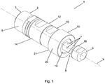
Figure 1 shows an axonometric view of the odorizer device that is the subject of the invention; -
Figure 2 shows a side sectional view of the odorizer device ofFigure 1 ; -
Figure 3 shows an enlarged detail ofFigure 2 ; -
Figure 4 shows the odorizer device of the invention in an operating configuration. - The odorizer device of the invention, indicated as a whole by 1 in
Figure 4 , is particularly suited to be used to odorize natural gas or a similar gas flowing in aduct 29 of a distribution network. - As can be observed in
Figures 1 and2 , thedevice 1 comprises atubular jacket 10 developed according to a longitudinal axis X. - The
device 1 furthermore comprises acontainment element 2 sliding in thetubular jacket 10 according to the longitudinal axis X between a first position, in which anend portion 8 of thecontainment element 2 is arranged so that it is extracted from thetubular jacket 10, and a second position, in which the end portion is arranged so that it is retracted into thetubular jacket 10. - The
tubular jacket 10 can be connected to theduct 29 in a stable manner through coupling means 13, in such a way that theend portion 8 faces towards the inside of theduct 29, as can be observed inFigure 4 . - The
containment element 2 defines acavity 2a that develops according to the direction of the longitudinal axis X between aninlet mouth 3, opposing saidend portion 8, and a plurality ofseparate outlet mouths 7 defined on the external surface of theend portion 8 and arranged at the level of respective distinct positions according to the longitudinal axis X. - In particular, the
outlet mouths 7 are arranged in such a way that they can all be placed inside thetubular jacket 10 following the complete retraction of theend portion 8, so that they are all closed. - Preferably but not necessarily, each
outlet mouth 7 is a hole with cylindrical cross section. - According to a variant embodiment of the invention, not illustrated in the drawings, one or
more outlet mouths 7 are in the shape of corresponding slits mainly developed according to the direction of the longitudinal axis X. - In a further variant embodiment of the invention there is only one
outlet mouth 7 in the shape of a slit. - According to further variant embodiments of the invention, not illustrated in the drawings,
outlet mouths 7 can be provided which are carried out as a combination of the embodiments just described above. - In any case, the
outlet mouths 7 overally extend over a section of the longitudinal axis X having a length exceeding the maximum width of theoutlet mouths 7 in a direction that is orthogonal to the longitudinal axis X. - Furthermore, the
outlet mouths 7 are configured in such a way that they are closed by thetubular jacket 10 when thecontainment element 2 is arranged in said second position. - Said configuration is such that the overall stroke of the
containment element 2 that is required to uncover theoutlet mouths 7 completely exceeds the width of the latter, so as to allow their progressive opening. - The
device 1 comprises also afeeding element 9 suited to absorb an odorizingsubstance 28, said feeding element being housed in thecavity 2a with anend 9a projecting from theinlet mouth 3 and the opposite end arranged inside thecavity 2a itself. - Preferably but not necessarily, the
feeding element 9 is a wick, even if in variant embodiments of the invention it can be constituted by any element suited to absorb theodorizing substance 28 and let it out through evaporation. Preferably, thefeeding element 9 is blocked axially with respect to thecontainment element 2 through fixing means that are not illustrated in the drawings but are known per se. - Gas tight means 11 suited to prevent the gas that flows in the
duct 29 from leaking outside through thedevice 1 are interposed between thetubular jacket 10 and thecontainment element 2. - Said gas-tight means 11 preferably comprise two sealing rings arranged in corresponding housings obtained in the side of the
tubular jacket 10 facing thecontainment element 2. - Clearly, according to variant embodiments of the invention, said gas-
tight means 11 can be present in a different number and/or can have a different shape than described above, provided that they are suited to prevent any gas leakage between thetubular jacket 10 and thecontainment element 2. - The
device 1 comprises also adjusting means 12 that maintain thecontainment element 2 in axial position with respect to thetubular jacket 10 but that can be operated in such a way as to cause thecontainment element 2 to slide in thetubular jacket 10 so as to modify said axial position. - In particular, said sliding movement is such as to allow the
end portion 8 to be retracted in thetubular jacket 10 and to be extracted from the same. - In the configuration shown in the figures, the
end portion 8 is completely extracted and, therefore, theoutlet mouths 7 are all exposed to the gas flowing in theduct 29. - In this way, the
odorizing substance 28 can evaporate from thecavity 2a through the entire cross section of theoutlet mouths 7, so as to odorize the gas. - Starting from the configuration mentioned above and acting on the adjusting means 12, it is possible to retract the
end portion 8 of thecontainment element 2 into thetubular jacket 10, in such a way as to obtain the more or less partial obstruction of theoutlet mouths 7 and, consequently, to adjust the passage area for the odorizingsubstance 28. - Obviously, said adjustment takes place in an analogous way in all the variant embodiments of the
device 1 described above. - It can be understood that, for a given configuration of the
outlet mouths 7, said passage area is independent of the gas speed and depends only on the position of thecontainment element 2 with respect to thetubular jacket 10. - In particular, as the
feeding element 9 does not project through theoutlet mouths 7, it maintains its position independently of the gas speed. - Consequently it is possible, for example through laboratory tests, to establish a relation between the speed of the gas that comes into contact with the
end portion 8 and the area of theoutlet mouths 7 which has to remain exposed as a whole in order to maintain the concentration of the odorizingsubstance 28 in the gas within the pre-established limits. - Therefore, the invention achieves the object to make the adjustment of the flow rate of the odorizing
substance 28 simpler and more reliable. - In the variant in which the
outlet mouths 7 are a plurality of distinct openings, the adjustment takes place through discrete variations that depend on the number of openings exposed to the flow. - Therefore, said variant offers the additional advantage that it does not require high precision in the positioning of the
containment element 2 with respect to thetubular jacket 10, thus further increasing the ease of adjustment of thedevice 1. - Preferably, the
feeding element 9 is arranged in thecavity 2a in such a way that it faces all theoutlet mouths 7 over their entire length. - Advantageously, said layout ensures the efficient evaporation of the odorizing
substance 28 through all of theoutlet mouths 7 and, therefore, increases the reliability of the adjustment operation. - Preferably, the
outlet mouths 7 constitute the only ways of communication towards the outside of thecavity 2a through theend portion 8. - Advantageously, said configuration ensures that the evaporation of the odorizing
substance 28 in theduct 29 takes place exclusively through theoutlet mouths 7, in such a way as to make it possible to interrupt the distribution of the odorizingsubstance 28. - Preferably, the condition described above is obtained by means of a sealing
ring 18 belonging to theend portion 8 and configured in such a way that it can be arranged against areference surface 19 defined on thetubular jacket 10 so as to prevent the outflow of the odorizingsubstance 28 through theoutlet mouths 7. - Advantageously, said sealing
ring 18 makes it possible to completely close theodorizer device 1 towards theduct 29, which is useful, for example, during maintenance operations or when it is necessary to interrupt the distribution of gas. - The sealing
ring 18 may belong to aplug 5 connected to theend portion 8, for example through a screwing action. - As regards the shape of the
outlet mouths 7, preferably their width in the direction perpendicular to the longitudinal axis X generally decreases as their distance from theinlet mouth 3 increases. - The applicant of the present invention has observed that said variation in the cross section of the
outlet mouths 7 makes it possible to establish a substantially proportional relation between the gas flow rate and the overall length of theoutlet mouths 7 which are extracted, in order to obtain the predetermined concentration of odorizingsubstance 28. - In the case where the
outlet mouths 7 are constituted by a plurality of holes arranged in different positions along the longitudinal axis X, the condition described above is obtained by defining for said holes diameters that decrease as their distance from theinlet mouth 3 increases. - If, instead, there is just one
outlet mouth 7 in the shape of a slit, said requisite can be met by making the slit with decreasing cross section towards the end opposite theinlet mouth 3. - If there are
outlet mouths 7 in the shape of holes, these are preferably arranged at regular intervals along the longitudinal axis X, in such a way that the number of holes which are extracted is proportional to the length over which thecontainment element 2 slides in thetubular jacket 10. - As regards the adjusting means 12, they preferably comprise screw means that connect the
containment element 2 to thetubular jacket 10, are suited to maintain the mutual axial position of the two elements and at the same time can be rotated in such a way as to adjust said mutual axial position. - Preferably and as shown in
Figure 3 , said screw means comprise afirst sleeve 14 provided with a firstinner thread 15 that is coupled with a correspondingouter thread 16 belonging to thetubular jacket 10 and with a secondinner thread 15a that is coupled with a correspondingouter thread 17 belonging to thecoupling element 2 and having opposite direction with respect to theouter thread 16. - Obviously, by rotating the
first sleeve 14 and maintaining the relative angular position between thecontainment element 2 and thetubular jacket 10 unchanged, it is possible to obtain opposing sliding movements of the two components with respect to thefirst sleeve 14 according to the longitudinal axis X, thus allowing an easy and quick adjustment of thedevice 1. - In order to maintain a fixed relative angular position between the
containment element 2 and thetubular jacket 10, one or both of the components are preferably provided with corresponding notches, not illustrated in the drawings, which allow the operator to check the angular position of the two components. - According to a variant embodiment of the invention, not illustrated in the drawings, the
first sleeve 14 is axially constrained to thecontainment element 2 or to thetubular jacket 10 and is coupled only to the other one of said two components through screw means. - Preferably, the
odorizer device 1 comprises reference notches, not illustrated in the drawings, on thefirst sleeve 14 and/or on thecontainment element 2 and/or on thetubular jacket 10, said reference notches being suited to indicate to the operator the length of the portion of theoutlet mouths 7 facing towards the outside of thetubular jacket 10 during the adjustment of thedevice 1. - Said notches can be arranged in different positions according to the longitudinal axis X at the level of those surfaces of the
containment element 2 and/or of thetubular jacket 10 that are progressively uncovered by thefirst sleeve 14 during the adjustment. - Preferably but not necessarily, the adjusting means 12 comprise also locking means, not illustrated herein but known per se, which can be activated at the end of the adjustment operation in order to prevent any further accidental rotation of the
first sleeve 14 due, for example, to vibrations or other causes. - Said locking means may comprise, for example, a fixing dowel.
- As regards the coupling means 13 suited to connect the
odorizer device 1 to theduct 29, these preferably comprise asecond sleeve 20 provided with connection means for stable connection to thetubular jacket 10. - Preferably, said stable connection means comprise a
stop surface 21 suited to be arranged against a correspondingreference surface 22 belonging to thetubular jacket 10, sealing means 23 being provided that prevent the passage of gas between thesecond sleeve 20 and thetubular jacket 10 and that preferably comprise an annular gasket. - Preferably, said stable connection is obtained by screwing the
second sleeve 20, provided with aninner thread 24, to thetubular jacket 10, provided with a correspondingouter thread 25, until thestop surface 21 comes to be positioned against thereference surface 22. - Said
second sleeve 20 is associated with theduct 29 through a welding operation or using any other equivalent connections means of the known type. Preferably and as shown inFigure 4 , the odorizingsubstance 28 is contained in areservoir 26 provided with amouth 27. - The
odorizer device 1 comprises joiningmeans 6 for the tight coupling of thecontainment element 2 with saidmouth 27, in such a way that theinlet mouth 3 of thecavity 2a is in communication with the inside of thereservoir 26. - Preferably, said joining
means 6 comprise an outer thread 6a belonging to thecontainment element 2 and screwed to a corresponding inner thread belonging to saidmouth 27 of thereservoir 26. - Preferably, the
feeding element 9 has itsend 9a that projects beyond theinlet mouth 3, so that the latter can be arranged inside thereservoir 26 in such a way as to effectively absorb the odorizingsubstance 28 independently of the position of thereservoir 26 with respect to theodorizer device 1. - Operatively, the
odorizer device 1 described above can be used after fixing thesecond sleeve 20 to theduct 29 in which the gas flows, for example through a welding operation, as shown inFigure 3 . - Thus, the
reservoir 26 is screwed to theodorizer device 1 by proceeding as described above, after which thetubular jacket 10 is screwed to thesecond sleeve 20, in such a way as to arrange thecontainment element 2 with itsend portion 8 facing the inside of theduct 29. - At this point, it is possible to adjust the
odorizer device 1 by acting on thefirst sleeve 14, as described above. - Advantageously, the
odorizer device 1 described above can be easily removed for maintenance purposes or when it is necessary to fill thereservoir 26 with odorizingsubstance 28. - According to the above description, it can be understood that the odorizer device that is the subject of the invention achieves all of the set objects.
- In particular, the position of the feeding element inside the containment element and the configuration of the outlet mouths facilitate the adjustment of the odorizer device, making it a quick and reliable operation.
Claims (16)
- Odorizer device (1) for gas distribution networks, comprising:- a tubular jacket (10) developing according to a longitudinal axis (X);- a feeding element (9) suited to absorb an odorizing substance (28) and to transfer it through evaporation, arranged in said tubular jacket (10);- coupling means (13) for the stable connection of said tubular jacket (10) to a duct (29);characterized in that it comprises:- a containment element (2) slidingly arranged in said tubular jacket (10) according to said longitudinal axis (X);- adjusting means (12) suited to maintain the mutual axial position between said tubular jacket (10) and said containment element (2) and suited to be operated to cause said containment element (2) to slide with respect to said tubular jacket (10) between a first position, in which an end portion (8) of said containment element (2) is arranged outside of said tubular jacket (10), and a second position, in which said end portion (8) is arranged inside said tubular jacket (10);- gas tight means (11) interposed between said tubular jacket (10) and said containment element (2);- a cavity (2a) belonging to said containment element (2), developed according to the direction of said longitudinal axis (X) between an inlet mouth (3) opposing said end portion (8) and one or more outlet mouths (7) defined on the external surface of said end portion (8), the whole of said outlet mouths extending over a portion of said longitudinal axis (X) whose length exceeds the maximum width of said outlet mouths (7) according to a direction that is orthogonal to said longitudinal axis (X), said outlet mouths (7) being configured in such a way that they are closed by said tubular jacket (10) when said containment element (2) is arranged in said second position;said feeding element (9) being arranged in said cavity (2a).
- Odorizer device (1) according to claim 1, characterized in that said one or more outlet mouths (7) comprise a plurality of separate outlet mouths (7), arranged in corresponding distinct positions along the direction of said longitudinal axis (X).
- Odorizer device (1) according to any of the preceding claims, characterized in that said one or more outlet mouths (7) comprise a slit.
- Odorizer device (1) according to any of the preceding claims, characterized in that the width of said one or more outlet mouths (7), according to a direction that is orthogonal to said longitudinal axis (X), generally decreases as the distance from said inlet mouth (3) increases.
- Odorizer device (1) according to any of the preceding claims, characterized in that said adjusting means (12) comprise screw means interposed between said containment element (2) and said tubular jacket (10).
- Odorizer device (1) according to claim 5, characterized in that said screw means comprise a first sleeve (14) provided with a first inner thread (15) that is coupled with an outer thread (16) belonging to said tubular jacket (10), and with a second inner thread (15a) that is coupled with an outer thread (17) belonging to said containment element (2) and having opposite direction with respect to said outer thread (16) of said tubular jacket (10).
- Odorizer device (1) according to claim 5 or 6, characterized in that it comprises reference notches on said first sleeve (14) and/or on said containment element (2) and/or on said tubular jacket (10), said notches being suited to indicate to an operator the length of the portion of said one or more outlet mouths (7) projecting from said tubular jacket (10).
- Odorizer device (1) according to any of the preceding claims, characterized in that said cavity (2a) communicates with the outside through said end portion (8), exclusively through said one or more outlet mouths (7).
- Odorizer device (1) according to claim 8, characterized in that said tubular jacket (10) defines a reference surface (19), said end portion (8) comprising a sealing ring (18) suited to be arranged against said reference surface (19) in such a way as to prevent said odorizing substance (28) from escaping through said outlet mouths (7).
- Odorizer device (1) according to any of the preceding claims, characterized in that it comprises a second sleeve (20) suited to be stably connected to said tubular jacket (10) and provided with a stop surface (21) suited to be arranged against a corresponding reference surface (22) belonging to said tubular jacket (10), sealing means (23) being present that are suited to prevent the passage of gas between said second sleeve (20) and said tubular jacket (10).
- Odorizer device (1) according to claim 10, characterized in that said second sleeve (20) comprises an inner thread (24) suited to be screwed to an outer thread (25) belonging to said tubular jacket (10).
- Odorizer device (1) according to any of the preceding claims, characterized in that it comprises fixing means suited to lock the axial movement of said feeding element (9) with respect to said containment element (2).
- Odorizer device (1) according to any of the preceding claims, characterized in that it comprises joining means (6) suited to sealingly connect said inlet mouth (3) to a reservoir (26).
- Odorizer device (1) according to claim 13, characterized in that it comprises a reservoir (26) containing said odorizing substance (28), provided with a mouth (27) that is coupled with said inlet mouth (3) through said joining means (6), said feeding element (9) being placed in contact with said odorizing substance (28).
- Odorizer device (1) according to any of the preceding claims, characterized in that said feeding element (9) is a wick.
- Odorizer device (1) according to any of the preceding claims, characterized in that it is suited to be used in distribution networks for natural gas or similar gases.
Priority Applications (1)
| Application Number | Priority Date | Filing Date | Title |
|---|---|---|---|
| SI201531147T SI3221037T1 (en) | 2014-11-18 | 2015-11-17 | Odorizer device for gas distribution networks |
Applications Claiming Priority (2)
| Application Number | Priority Date | Filing Date | Title |
|---|---|---|---|
| ITVI20140298 | 2014-11-18 | ||
| PCT/IB2015/058885 WO2016079673A1 (en) | 2014-11-18 | 2015-11-17 | Odorizer device for gas distribution networks |
Publications (2)
| Publication Number | Publication Date |
|---|---|
| EP3221037A1 EP3221037A1 (en) | 2017-09-27 |
| EP3221037B1 true EP3221037B1 (en) | 2020-01-08 |
Family
ID=52355112
Family Applications (1)
| Application Number | Title | Priority Date | Filing Date |
|---|---|---|---|
| EP15820262.2A Active EP3221037B1 (en) | 2014-11-18 | 2015-11-17 | Odorizer device for gas distribution networks |
Country Status (3)
| Country | Link |
|---|---|
| EP (1) | EP3221037B1 (en) |
| SI (1) | SI3221037T1 (en) |
| WO (1) | WO2016079673A1 (en) |
Families Citing this family (1)
| Publication number | Priority date | Publication date | Assignee | Title |
|---|---|---|---|---|
| CN117432946B (en) * | 2023-12-19 | 2024-03-08 | 上海叁零肆零科技有限公司 | Simulation-combined gradient distributed town gas intelligent odorizing method and system |
Family Cites Families (2)
| Publication number | Priority date | Publication date | Assignee | Title |
|---|---|---|---|---|
| GB861245A (en) * | 1956-06-01 | 1961-02-15 | Sterling Ind Ltd | Improvements in and relating to gas conditioning devices |
| FR2255943B1 (en) * | 1973-12-27 | 1978-06-02 | Comp Generale Electricite |
-
2015
- 2015-11-17 SI SI201531147T patent/SI3221037T1/en unknown
- 2015-11-17 WO PCT/IB2015/058885 patent/WO2016079673A1/en not_active Ceased
- 2015-11-17 EP EP15820262.2A patent/EP3221037B1/en active Active
Non-Patent Citations (1)
| Title |
|---|
| None * |
Also Published As
| Publication number | Publication date |
|---|---|
| WO2016079673A1 (en) | 2016-05-26 |
| EP3221037A1 (en) | 2017-09-27 |
| SI3221037T1 (en) | 2020-06-30 |
Similar Documents
| Publication | Publication Date | Title |
|---|---|---|
| US3187775A (en) | Flow bean | |
| RU2015139904A (en) | THERMOSTATIC CARTRIDGE FOR REGULATION OF HOT AND COLD LIQUIDS WHICH MUST BE MIXED | |
| NO752307L (en) | ||
| CA2650746C (en) | Angled diffuser and steam injection heater assembly | |
| PT1492970E (en) | VALVE ASSEMBLY. | |
| DE2642922A1 (en) | AXLE BEARING AND SEAL FOR THROTTLE FLAP VALVES | |
| NO135951B (en) | ||
| US10053842B2 (en) | Sanitary fitting | |
| EP3221037A1 (en) | Odorizer device for gas distribution networks | |
| KR102533989B1 (en) | Nozzle Type Steam Trap | |
| DE102013221082A1 (en) | hydraulic cylinders | |
| US9759386B2 (en) | Reducing friction of a viscous fluid flow in a conduit | |
| US10458563B2 (en) | Valve arrangement | |
| DK154856B (en) | DEVICE FOR REGULATING THE QUANTITY AND / OR MIXING RELATIONSHIP OF TWO GAS AND / OR CLEANING FLOWS | |
| US10702094B2 (en) | Device for continuous heating of fluids | |
| DE112013004209T5 (en) | expansion tank | |
| MX375658B (en) | A REACTOR FOR MIXING LIQUID, GAS AND SOLID MATERIAL. | |
| US20110036866A1 (en) | Apparatus and method for synchronized flow from volumetric tanks | |
| DE60009473T2 (en) | ROTATABLE COUPLING FOR LIQUID-LEADING CABLES | |
| US2349051A (en) | Mixing valve | |
| US1739360A (en) | Oil-regulating device | |
| EP3203192B1 (en) | Flowmeter for thermohydraulic systems | |
| DE2055062A1 (en) | Safety device that responds to pipe leaks | |
| DE2219745A1 (en) | HOT WATER PUMP WITH COOLED SEALING HOUSING | |
| CN220367026U (en) | Hand plunger valve sampler |
Legal Events
| Date | Code | Title | Description |
|---|---|---|---|
| STAA | Information on the status of an ep patent application or granted ep patent |
Free format text: STATUS: THE INTERNATIONAL PUBLICATION HAS BEEN MADE |
|
| PUAI | Public reference made under article 153(3) epc to a published international application that has entered the european phase |
Free format text: ORIGINAL CODE: 0009012 |
|
| STAA | Information on the status of an ep patent application or granted ep patent |
Free format text: STATUS: REQUEST FOR EXAMINATION WAS MADE |
|
| 17P | Request for examination filed |
Effective date: 20170619 |
|
| AK | Designated contracting states |
Kind code of ref document: A1 Designated state(s): AL AT BE BG CH CY CZ DE DK EE ES FI FR GB GR HR HU IE IS IT LI LT LU LV MC MK MT NL NO PL PT RO RS SE SI SK SM TR |
|
| AX | Request for extension of the european patent |
Extension state: BA ME |
|
| GRAP | Despatch of communication of intention to grant a patent |
Free format text: ORIGINAL CODE: EPIDOSNIGR1 |
|
| STAA | Information on the status of an ep patent application or granted ep patent |
Free format text: STATUS: GRANT OF PATENT IS INTENDED |
|
| INTG | Intention to grant announced |
Effective date: 20190808 |
|
| RIN1 | Information on inventor provided before grant (corrected) |
Inventor name: DI DOMENICO, RENATO |
|
| GRAJ | Information related to disapproval of communication of intention to grant by the applicant or resumption of examination proceedings by the epo deleted |
Free format text: ORIGINAL CODE: EPIDOSDIGR1 |
|
| STAA | Information on the status of an ep patent application or granted ep patent |
Free format text: STATUS: REQUEST FOR EXAMINATION WAS MADE |
|
| GRAR | Information related to intention to grant a patent recorded |
Free format text: ORIGINAL CODE: EPIDOSNIGR71 |
|
| GRAS | Grant fee paid |
Free format text: ORIGINAL CODE: EPIDOSNIGR3 |
|
| STAA | Information on the status of an ep patent application or granted ep patent |
Free format text: STATUS: GRANT OF PATENT IS INTENDED |
|
| GRAA | (expected) grant |
Free format text: ORIGINAL CODE: 0009210 |
|
| STAA | Information on the status of an ep patent application or granted ep patent |
Free format text: STATUS: THE PATENT HAS BEEN GRANTED |
|
| INTC | Intention to grant announced (deleted) | ||
| AK | Designated contracting states |
Kind code of ref document: B1 Designated state(s): AL AT BE BG CH CY CZ DE DK EE ES FI FR GB GR HR HU IE IS IT LI LT LU LV MC MK MT NL NO PL PT RO RS SE SI SK SM TR |
|
| AX | Request for extension of the european patent |
Extension state: BA ME |
|
| INTG | Intention to grant announced |
Effective date: 20191202 |
|
| REG | Reference to a national code |
Ref country code: GB Ref legal event code: FG4D |
|
| REG | Reference to a national code |
Ref country code: CH Ref legal event code: EP |
|
| REG | Reference to a national code |
Ref country code: DE Ref legal event code: R096 Ref document number: 602015045309 Country of ref document: DE |
|
| REG | Reference to a national code |
Ref country code: IE Ref legal event code: FG4D |
|
| REG | Reference to a national code |
Ref country code: AT Ref legal event code: REF Ref document number: 1222000 Country of ref document: AT Kind code of ref document: T Effective date: 20200215 |
|
| REG | Reference to a national code |
Ref country code: RO Ref legal event code: EPE |
|
| REG | Reference to a national code |
Ref country code: NL Ref legal event code: MP Effective date: 20200108 |
|
| REG | Reference to a national code |
Ref country code: LT Ref legal event code: MG4D |
|
| PG25 | Lapsed in a contracting state [announced via postgrant information from national office to epo] |
Ref country code: PT Free format text: LAPSE BECAUSE OF FAILURE TO SUBMIT A TRANSLATION OF THE DESCRIPTION OR TO PAY THE FEE WITHIN THE PRESCRIBED TIME-LIMIT Effective date: 20200531 Ref country code: RS Free format text: LAPSE BECAUSE OF FAILURE TO SUBMIT A TRANSLATION OF THE DESCRIPTION OR TO PAY THE FEE WITHIN THE PRESCRIBED TIME-LIMIT Effective date: 20200108 Ref country code: FI Free format text: LAPSE BECAUSE OF FAILURE TO SUBMIT A TRANSLATION OF THE DESCRIPTION OR TO PAY THE FEE WITHIN THE PRESCRIBED TIME-LIMIT Effective date: 20200108 Ref country code: NO Free format text: LAPSE BECAUSE OF FAILURE TO SUBMIT A TRANSLATION OF THE DESCRIPTION OR TO PAY THE FEE WITHIN THE PRESCRIBED TIME-LIMIT Effective date: 20200408 Ref country code: NL Free format text: LAPSE BECAUSE OF FAILURE TO SUBMIT A TRANSLATION OF THE DESCRIPTION OR TO PAY THE FEE WITHIN THE PRESCRIBED TIME-LIMIT Effective date: 20200108 Ref country code: LT Free format text: LAPSE BECAUSE OF FAILURE TO SUBMIT A TRANSLATION OF THE DESCRIPTION OR TO PAY THE FEE WITHIN THE PRESCRIBED TIME-LIMIT Effective date: 20200108 |
|
| PG25 | Lapsed in a contracting state [announced via postgrant information from national office to epo] |
Ref country code: IS Free format text: LAPSE BECAUSE OF FAILURE TO SUBMIT A TRANSLATION OF THE DESCRIPTION OR TO PAY THE FEE WITHIN THE PRESCRIBED TIME-LIMIT Effective date: 20200508 Ref country code: BG Free format text: LAPSE BECAUSE OF FAILURE TO SUBMIT A TRANSLATION OF THE DESCRIPTION OR TO PAY THE FEE WITHIN THE PRESCRIBED TIME-LIMIT Effective date: 20200408 Ref country code: HR Free format text: LAPSE BECAUSE OF FAILURE TO SUBMIT A TRANSLATION OF THE DESCRIPTION OR TO PAY THE FEE WITHIN THE PRESCRIBED TIME-LIMIT Effective date: 20200108 Ref country code: SE Free format text: LAPSE BECAUSE OF FAILURE TO SUBMIT A TRANSLATION OF THE DESCRIPTION OR TO PAY THE FEE WITHIN THE PRESCRIBED TIME-LIMIT Effective date: 20200108 Ref country code: LV Free format text: LAPSE BECAUSE OF FAILURE TO SUBMIT A TRANSLATION OF THE DESCRIPTION OR TO PAY THE FEE WITHIN THE PRESCRIBED TIME-LIMIT Effective date: 20200108 Ref country code: GR Free format text: LAPSE BECAUSE OF FAILURE TO SUBMIT A TRANSLATION OF THE DESCRIPTION OR TO PAY THE FEE WITHIN THE PRESCRIBED TIME-LIMIT Effective date: 20200409 |
|
| REG | Reference to a national code |
Ref country code: DE Ref legal event code: R097 Ref document number: 602015045309 Country of ref document: DE |
|
| PG25 | Lapsed in a contracting state [announced via postgrant information from national office to epo] |
Ref country code: DK Free format text: LAPSE BECAUSE OF FAILURE TO SUBMIT A TRANSLATION OF THE DESCRIPTION OR TO PAY THE FEE WITHIN THE PRESCRIBED TIME-LIMIT Effective date: 20200108 Ref country code: ES Free format text: LAPSE BECAUSE OF FAILURE TO SUBMIT A TRANSLATION OF THE DESCRIPTION OR TO PAY THE FEE WITHIN THE PRESCRIBED TIME-LIMIT Effective date: 20200108 Ref country code: SK Free format text: LAPSE BECAUSE OF FAILURE TO SUBMIT A TRANSLATION OF THE DESCRIPTION OR TO PAY THE FEE WITHIN THE PRESCRIBED TIME-LIMIT Effective date: 20200108 Ref country code: EE Free format text: LAPSE BECAUSE OF FAILURE TO SUBMIT A TRANSLATION OF THE DESCRIPTION OR TO PAY THE FEE WITHIN THE PRESCRIBED TIME-LIMIT Effective date: 20200108 Ref country code: SM Free format text: LAPSE BECAUSE OF FAILURE TO SUBMIT A TRANSLATION OF THE DESCRIPTION OR TO PAY THE FEE WITHIN THE PRESCRIBED TIME-LIMIT Effective date: 20200108 |
|
| VS25 | Lapsed in a validation state [announced via postgrant information from nat. office to epo] |
Ref country code: MD Free format text: LAPSE BECAUSE OF FAILURE TO SUBMIT A TRANSLATION OF THE DESCRIPTION OR TO PAY THE FEE WITHIN THE PRESCRIBED TIME-LIMIT Effective date: 20200108 |
|
| PLBE | No opposition filed within time limit |
Free format text: ORIGINAL CODE: 0009261 |
|
| STAA | Information on the status of an ep patent application or granted ep patent |
Free format text: STATUS: NO OPPOSITION FILED WITHIN TIME LIMIT |
|
| REG | Reference to a national code |
Ref country code: AT Ref legal event code: MK05 Ref document number: 1222000 Country of ref document: AT Kind code of ref document: T Effective date: 20200108 |
|
| 26N | No opposition filed |
Effective date: 20201009 |
|
| PG25 | Lapsed in a contracting state [announced via postgrant information from national office to epo] |
Ref country code: AT Free format text: LAPSE BECAUSE OF FAILURE TO SUBMIT A TRANSLATION OF THE DESCRIPTION OR TO PAY THE FEE WITHIN THE PRESCRIBED TIME-LIMIT Effective date: 20200108 |
|
| PG25 | Lapsed in a contracting state [announced via postgrant information from national office to epo] |
Ref country code: PL Free format text: LAPSE BECAUSE OF FAILURE TO SUBMIT A TRANSLATION OF THE DESCRIPTION OR TO PAY THE FEE WITHIN THE PRESCRIBED TIME-LIMIT Effective date: 20200108 |
|
| VS25 | Lapsed in a validation state [announced via postgrant information from nat. office to epo] |
Ref country code: MA Free format text: LAPSE BECAUSE OF FAILURE TO SUBMIT A TRANSLATION OF THE DESCRIPTION OR TO PAY THE FEE WITHIN THE PRESCRIBED TIME-LIMIT Effective date: 20200108 |
|
| PG25 | Lapsed in a contracting state [announced via postgrant information from national office to epo] |
Ref country code: MC Free format text: LAPSE BECAUSE OF FAILURE TO SUBMIT A TRANSLATION OF THE DESCRIPTION OR TO PAY THE FEE WITHIN THE PRESCRIBED TIME-LIMIT Effective date: 20200108 |
|
| REG | Reference to a national code |
Ref country code: CH Ref legal event code: PL |
|
| GBPC | Gb: european patent ceased through non-payment of renewal fee |
Effective date: 20201117 |
|
| PG25 | Lapsed in a contracting state [announced via postgrant information from national office to epo] |
Ref country code: LU Free format text: LAPSE BECAUSE OF NON-PAYMENT OF DUE FEES Effective date: 20201117 |
|
| REG | Reference to a national code |
Ref country code: BE Ref legal event code: MM Effective date: 20201130 |
|
| PG25 | Lapsed in a contracting state [announced via postgrant information from national office to epo] |
Ref country code: LI Free format text: LAPSE BECAUSE OF NON-PAYMENT OF DUE FEES Effective date: 20201130 Ref country code: CH Free format text: LAPSE BECAUSE OF NON-PAYMENT OF DUE FEES Effective date: 20201130 |
|
| PG25 | Lapsed in a contracting state [announced via postgrant information from national office to epo] |
Ref country code: IE Free format text: LAPSE BECAUSE OF NON-PAYMENT OF DUE FEES Effective date: 20201117 Ref country code: FR Free format text: LAPSE BECAUSE OF NON-PAYMENT OF DUE FEES Effective date: 20201130 |
|
| REG | Reference to a national code |
Ref country code: DE Ref legal event code: R079 Ref document number: 602015045309 Country of ref document: DE Free format text: PREVIOUS MAIN CLASS: B01F0005040000 Ipc: B01F0025300000 |
|
| PG25 | Lapsed in a contracting state [announced via postgrant information from national office to epo] |
Ref country code: GB Free format text: LAPSE BECAUSE OF NON-PAYMENT OF DUE FEES Effective date: 20201117 |
|
| PG25 | Lapsed in a contracting state [announced via postgrant information from national office to epo] |
Ref country code: MT Free format text: LAPSE BECAUSE OF FAILURE TO SUBMIT A TRANSLATION OF THE DESCRIPTION OR TO PAY THE FEE WITHIN THE PRESCRIBED TIME-LIMIT Effective date: 20200108 Ref country code: CY Free format text: LAPSE BECAUSE OF FAILURE TO SUBMIT A TRANSLATION OF THE DESCRIPTION OR TO PAY THE FEE WITHIN THE PRESCRIBED TIME-LIMIT Effective date: 20200108 |
|
| PG25 | Lapsed in a contracting state [announced via postgrant information from national office to epo] |
Ref country code: MK Free format text: LAPSE BECAUSE OF FAILURE TO SUBMIT A TRANSLATION OF THE DESCRIPTION OR TO PAY THE FEE WITHIN THE PRESCRIBED TIME-LIMIT Effective date: 20200108 Ref country code: AL Free format text: LAPSE BECAUSE OF FAILURE TO SUBMIT A TRANSLATION OF THE DESCRIPTION OR TO PAY THE FEE WITHIN THE PRESCRIBED TIME-LIMIT Effective date: 20200108 |
|
| PG25 | Lapsed in a contracting state [announced via postgrant information from national office to epo] |
Ref country code: BE Free format text: LAPSE BECAUSE OF NON-PAYMENT OF DUE FEES Effective date: 20201130 |
|
| PGFP | Annual fee paid to national office [announced via postgrant information from national office to epo] |
Ref country code: RO Payment date: 20221107 Year of fee payment: 8 Ref country code: DE Payment date: 20221123 Year of fee payment: 8 Ref country code: CZ Payment date: 20221107 Year of fee payment: 8 |
|
| PGFP | Annual fee paid to national office [announced via postgrant information from national office to epo] |
Ref country code: SI Payment date: 20221103 Year of fee payment: 8 |
|
| PGFP | Annual fee paid to national office [announced via postgrant information from national office to epo] |
Ref country code: TR Payment date: 20231116 Year of fee payment: 9 Ref country code: IT Payment date: 20231010 Year of fee payment: 9 |
|
| REG | Reference to a national code |
Ref country code: DE Ref legal event code: R119 Ref document number: 602015045309 Country of ref document: DE |
|
| PG25 | Lapsed in a contracting state [announced via postgrant information from national office to epo] |
Ref country code: CZ Free format text: LAPSE BECAUSE OF NON-PAYMENT OF DUE FEES Effective date: 20231117 |
|
| PG25 | Lapsed in a contracting state [announced via postgrant information from national office to epo] |
Ref country code: RO Free format text: LAPSE BECAUSE OF NON-PAYMENT OF DUE FEES Effective date: 20231117 Ref country code: CZ Free format text: LAPSE BECAUSE OF NON-PAYMENT OF DUE FEES Effective date: 20231117 Ref country code: SI Free format text: LAPSE BECAUSE OF NON-PAYMENT OF DUE FEES Effective date: 20231118 |
|
| REG | Reference to a national code |
Ref country code: SI Ref legal event code: KO00 Effective date: 20240813 |
|
| PG25 | Lapsed in a contracting state [announced via postgrant information from national office to epo] |
Ref country code: DE Free format text: LAPSE BECAUSE OF NON-PAYMENT OF DUE FEES Effective date: 20240601 |
|
| PG25 | Lapsed in a contracting state [announced via postgrant information from national office to epo] |
Ref country code: DE Free format text: LAPSE BECAUSE OF NON-PAYMENT OF DUE FEES Effective date: 20240601 |
|
| PG25 | Lapsed in a contracting state [announced via postgrant information from national office to epo] |
Ref country code: IT Free format text: LAPSE BECAUSE OF NON-PAYMENT OF DUE FEES Effective date: 20241117 |
|
| PG25 | Lapsed in a contracting state [announced via postgrant information from national office to epo] |
Ref country code: TR Free format text: LAPSE BECAUSE OF NON-PAYMENT OF DUE FEES Effective date: 20241117 |