EP3220869B1 - Tiltable patient ceiling lift assembly - Google Patents
Tiltable patient ceiling lift assembly Download PDFInfo
- Publication number
- EP3220869B1 EP3220869B1 EP15860173.2A EP15860173A EP3220869B1 EP 3220869 B1 EP3220869 B1 EP 3220869B1 EP 15860173 A EP15860173 A EP 15860173A EP 3220869 B1 EP3220869 B1 EP 3220869B1
- Authority
- EP
- European Patent Office
- Prior art keywords
- lift system
- ceiling lift
- ceiling
- motor units
- patient
- Prior art date
- Legal status (The legal status is an assumption and is not a legal conclusion. Google has not performed a legal analysis and makes no representation as to the accuracy of the status listed.)
- Active
Links
Images



Classifications
-
- A—HUMAN NECESSITIES
- A61—MEDICAL OR VETERINARY SCIENCE; HYGIENE
- A61G—TRANSPORT, PERSONAL CONVEYANCES, OR ACCOMMODATION SPECIALLY ADAPTED FOR PATIENTS OR DISABLED PERSONS; OPERATING TABLES OR CHAIRS; CHAIRS FOR DENTISTRY; FUNERAL DEVICES
- A61G7/00—Beds specially adapted for nursing; Devices for lifting patients or disabled persons
- A61G7/10—Devices for lifting patients or disabled persons, e.g. special adaptations of hoists thereto
- A61G7/104—Devices carried or supported by
- A61G7/1042—Rail systems
-
- A—HUMAN NECESSITIES
- A61—MEDICAL OR VETERINARY SCIENCE; HYGIENE
- A61G—TRANSPORT, PERSONAL CONVEYANCES, OR ACCOMMODATION SPECIALLY ADAPTED FOR PATIENTS OR DISABLED PERSONS; OPERATING TABLES OR CHAIRS; CHAIRS FOR DENTISTRY; FUNERAL DEVICES
- A61G7/00—Beds specially adapted for nursing; Devices for lifting patients or disabled persons
- A61G7/10—Devices for lifting patients or disabled persons, e.g. special adaptations of hoists thereto
- A61G7/1013—Lifting of patients by
- A61G7/1015—Cables, chains or cords
-
- A—HUMAN NECESSITIES
- A61—MEDICAL OR VETERINARY SCIENCE; HYGIENE
- A61G—TRANSPORT, PERSONAL CONVEYANCES, OR ACCOMMODATION SPECIALLY ADAPTED FOR PATIENTS OR DISABLED PERSONS; OPERATING TABLES OR CHAIRS; CHAIRS FOR DENTISTRY; FUNERAL DEVICES
- A61G7/00—Beds specially adapted for nursing; Devices for lifting patients or disabled persons
- A61G7/10—Devices for lifting patients or disabled persons, e.g. special adaptations of hoists thereto
- A61G7/1025—Lateral movement of patients, e.g. horizontal transfer
- A61G7/1034—Rollers, rails or other means
-
- A—HUMAN NECESSITIES
- A61—MEDICAL OR VETERINARY SCIENCE; HYGIENE
- A61G—TRANSPORT, PERSONAL CONVEYANCES, OR ACCOMMODATION SPECIALLY ADAPTED FOR PATIENTS OR DISABLED PERSONS; OPERATING TABLES OR CHAIRS; CHAIRS FOR DENTISTRY; FUNERAL DEVICES
- A61G7/00—Beds specially adapted for nursing; Devices for lifting patients or disabled persons
- A61G7/10—Devices for lifting patients or disabled persons, e.g. special adaptations of hoists thereto
- A61G7/1049—Attachment, suspending or supporting means for patients
- A61G7/1051—Flexible harnesses or slings
-
- A—HUMAN NECESSITIES
- A61—MEDICAL OR VETERINARY SCIENCE; HYGIENE
- A61G—TRANSPORT, PERSONAL CONVEYANCES, OR ACCOMMODATION SPECIALLY ADAPTED FOR PATIENTS OR DISABLED PERSONS; OPERATING TABLES OR CHAIRS; CHAIRS FOR DENTISTRY; FUNERAL DEVICES
- A61G7/00—Beds specially adapted for nursing; Devices for lifting patients or disabled persons
- A61G7/10—Devices for lifting patients or disabled persons, e.g. special adaptations of hoists thereto
- A61G7/1073—Parts, details or accessories
- A61G7/1076—Means for rotating around a vertical axis
Definitions
- the present disclosure relates to a patient ceiling lift assembly for use, for example, in a hospital or care home.
- Ceiling lifts for lifting and transporting patients have been in use for over twenty years. These types of patient lift are becoming more popular as they take up little space in a hospital or care home environment and are more efficient than floor lifts.
- a ceiling lift can be described as a motor unit able to move along one or more rails arranged as a rail system, fixed to the ceiling.
- a flexible member such as a strap extends from the motor unit and is attached to a spreader bar.
- a patient sling or harness is attached to the spreader bar.
- An electrically motorized mechanism in the motor unit allows the user to extend or shorten the strap so as to raise or lower the spreader bar and with this to raise or lower the sling and any patient carried in the sling.
- the combination of rail system, motor unit, spreader bar and sling is often referred to as a ceiling lift system.
- Some ceiling lift systems are said to be fixed (the motor unit is dedicated to one room) while others are said to be portable (the motor unit can move around from room to room).
- One design adopted by manufacturers for handling patients of very large size has two motor units with two spreader bars which operate together.
- one of the motor units and its associated spreader bar supports/lifts the shoulder section of the patient, while the other motor unit and spreader bar supports/lifts the patient's leg section.
- a key benefit of such solution is the ability to provide a tilting function to sit or recline the patient during transfer, by creating a height difference between the spreader bars. Bringing the leg section spreader bar above the shoulder section spreader bar leads to a patient reclined position, while bringing the leg section spreader bar below the shoulder section spreader bar leads to a patient sitting position.
- a tilting function can increase patient comfort and reduce caregiver effort to transfer a patient.
- Care institutions face the challenge of making the care environment, typically the patient rooms, as versatile as possible when it comes to the range of patients they can handle. As a result the patient environment should be able to accommodate very large patients but also very small patients. Otherwise, a room dedicated for very large sized patients can often be unoccupied for long periods of time.
- Ceiling lift systems based on the use of two motor units and two spreader bars can be arranged to have the motor units able to move apart from one another, for example slidably located on a support rail, or can be fixed in position. While an arrangement which allows for the motor units to move apart can better accommodate a large patient, they can suffer from a loss of compactness of the apparatus and from loss of strength of the assembly. Fixed motor units can, however, only accommodate larger patients awkwardly.
- the present disclosure relates to an improved patient ceiling lift system.
- a patient ceiling lift system including: first and second motor units; first and second tension support members each coupled to a respective one of the first and second motor units, each motor unit being operable to change an operative length of its associated strap element by extending or retracting the strap out of or into the motor unit, each strap element including a coupling for attachment to a patient sling; a support frame assembly to which the first and second motor units are attached, the support frame assembly including a coupling for a ceiling carrier system; wherein the support frame assembly includes first and second independent pivotable support members to which the first and second motor units are attached, whereby the motor units are able to pivot on the support frame and relative to one another.
- a patient ceiling lift system that includes first and second motor units; first and second tension support members each coupled to a respective one of the first and second motor units.
- Each motor unit is operable to change the operative length of its associated tension support member element by extending or retracting the tension support member out of or into the motor unit.
- the motor units are attached to first and second independent pivotable support members of a support frame assembly which also includes a coupling for a ceiling carrier system.
- the motor units are able to pivot on the support frame and relative to one another, which enables the motor units to follow the loading direction on the tension support member and eliminate motor unit side loading.
- the pivoting of the motor units also effectively increases the horizontal distance of between the points of origin of the flexible load supporting tension support member, which reduces the shear stress on a patient when in the reclined position.
- the structure can also provide a compact device while maximizing patient room in the reclined position.
- the provision of a pivoting motion to the motor units enables them to turn in the direction of a pulling force on the straps, enabling them between to accommodate the spacing between the straps or other tension support members of a sling. This improves the operation of the motor units. Moreover, the arrangement can avoid the need to have motor units which are able to move apart, and can therefore contribute to a more compact system at reduced cost. Other embodiments combine the concept of tiltable motor units with a system which enables the distance between the motor units to be changed, for example by having the motor units mounted on a rail.
- the pivotable support members are able to rotate by between 15 and 25 degrees. It has been found that such a range of pivoting meets the requirements of ceiling lift systems, although the range could be extended to greater pivoting angles should the need arise, for instance where the ceiling height is particularly low.
- the pivotable support members are rectangular or square section tubular closed end elements having one or more connection points for connection to the motor units. Elements of such a shape enable good fixation of the motor units to the support members and also provide significant strength to the support members.
- the pivotable support members advantageously rotate about an axle at their closed ends.
- the support frame assembly includes first and second plate members disposed one over the other, the first plate member including the coupling for a ceiling carrier system and the pivotable support members being attached to the second plate member.
- the first and second plate members are connected to one another by a rotatable coupling enabling the first and second frame members to rotate relative to one another.
- the rotatable coupling can include first and second concentric ring elements rotatably coupled to one another, the first ring element being fixed to the first plate member and the second ring element being fixed to the second plate member.
- Such a coupling can be made to have a significant diameter, which enables the coupling to support very heavy weights and also asymmetric weights, for instance when just one of the motor units is used to support a patient.
- the first and second concentric ring elements have a diameter at least 50% of a width of the first and second plate members. They may, in practice, have a much greater diameter, typically just smaller than the width of the plate members.
- the first and second plate members each include a plurality of upstanding flange walls extending from a base plate element of the member. These walls contribute to the strength of the plate members and reduce their deformation when subjected to very heavy loads.
- the coupling for a ceiling carrier system is, in an embodiment, located on the upstanding flange walls of the first plate member.
- the coupling advantageously comprises a series of wheel elements.
- the rail coupling includes at least three pairs of wheel elements.
- first motor unit is a leading motor unit and the second motor unit is a driven motor unit.
- Each wheel element may include first and second coaxially mounted wheels, which may be disposed on opposite sides of an upstanding flange wall of the support frame assembly.
- FIG. 1 this shows a conventional ceiling lift system 10 which includes a rail 12 that is fixed to the ceiling structure of a patient care facility, such as a hospital, care home or the like.
- the rail 12 includes a downwardly depending channel 14.
- the system 10 may include a transmission, winding or coiling assembly, having for example a motor unit 16 which includes a wheel or roller (not shown) which runs within the downwardly depending channel 14 to allow the motor unit 16 to be moved in supported manner along the rail 12, as is known in the art.
- the motor unit 16 is operatively associated with, coupled to and/or includes a tensile support member, such as a flexible element or strap 18, which in practice is attached to a motorised spool or drum within the motor unit 16, and which can be unwound from the spool to lengthen the strap 18 and wound on the spool to shorten the strap 18, again in known manner.
- a tensile support member such as a flexible element or strap 18, which in practice is attached to a motorised spool or drum within the motor unit 16, and which can be unwound from the spool to lengthen the strap 18 and wound on the spool to shorten the strap 18, again in known manner.
- tensile support member may be operatively associated with, coupled to and/or form part of a motor unit to facilitate patient support.
- the tensile support member is configured to be coilable about the drum or motorized spool of motor unit 16 and having sufficient tensile strength for lifting a patient.
- the support member may be rigid in tension along its length yet permit motion in other directions to dynamically support a patient, inclusive of bariatric patients.
- Exemplary support members may include webbing, belts, rope, wire, cord, cable and chains.
- the strap 18 includes a coupler at its lower, free end, to which there can be attached a spreader bar 20, again of known form.
- the coupling can be any fastener, connector, attachment or securement mechanism suitable for connection to spreader bar 20.
- the spreader bar 20 includes coupling points 22, which are spaced from one another and specifically at either end of the bar 20.
- the coupling points 22 act as attachments for a sling 24, as shown in Figure 2 .
- the sling 24 is provided with a plurality of straps 26, 28, which attach to the coupling points 22 so that the sling 24 is held by the spreader bar 20 in an open condition to support a patient comfortably in the sling 24.
- These slings are well known in the art.
- the apparatus 30 includes two motor units 16 which are attached to a support unit 32, is coupled to the rail 12, as in the example of Figure 1 .
- the apparatus 30 includes two spreader bars 20, each attached to a respective strap 18 of a respective motor unit 16.
- the motor units 16 are spaced from one another so that one strap 18 and its associated spreader bar 20 can be located around the top of the patient's torso, whereas the other motor unit and spreader bar 20 is located around the patient's thigh position.
- a sling 34 includes pairs of straps 36, 38 coupling to respective spreader bars 20, which allow a patient to be held within the sling 34 in a gently reclining position as shown in the example of Figure 3 .
- the motor units 16 are operable to release and withdraw lengths of strap 18 such that the spreader bars 20 can be raised or lowered as required.
- the straps 18 can be lengthened to lower the spreader bars 20 towards a patient reclining on a bed and then wound into the motor units 16 to raise the spreader bars 20 and thus to raise the patient while carried in the sling 34.
- the motor units 18 are, for this purpose, controlled by a caregiver such as nurse, and are advantageously movable independently of one another when the patient is moved to different positions while suspended in the sling 34.
- the patient can be held in a substantially reclining position as shown in Figure 3 or could be raised to a sitting position, by raising the spreader bar 20 at the torso end of the patient.
- the patient ceiling lift apparatus 30 shown in Figure 3 spaces the motor units 16 from one another in order to have the motor units positioned generally vertically above the spreader bars when the sling is in the patient reclining position. While this is suitable in the configuration shown, spacing the motor units 16 in this manner leads to a larger assembly and also one which is not optimal for asymmetric use, that is using a single motor unit 16 only.
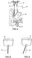
- Figure 4 shows an assembly 40 in which the two motor units 16 are positioned adjacent one another and which can be seen provides a more compact assembly that the example shown in Figure 3 .
- the assembly can also be stronger and better able to support asymmetric loads, for instance when using a single motor unit to carry a patient.
- the strap elements 18 are also close to one another. While this does not generally cause a problem with a smaller patient or with a patient in an upright sitting position, it does cause problems with larger patients.
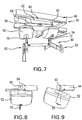
- the strap 18 can be seen extending from the motor unit 16 in a generally vertical orientation, as it is designed to do.
- the strap 16 can be seen extending at an angle to the vertical, as would occur when the assembly is supporting a sling/patient having greater distances between the two spreader bars, as can occur with a large patient and a patient in the reclining position.
- This imparts side stress on the motor unit 16, which it is not designed to withstand and which contributes to increased friction and wear.
- the motor units 16 and straps 18 are exposed to such stresses on a frequent or too numerous basis they can fail prematurely.
- the forces imparted to the sling will pull the sling to a closed position, causing shear stress on the patient, leading to patient discomfort.
- the assembly 50 includes first and second motor units 52, 54, which may be structurally the same as the motor units of the examples of Figures 1 and 3 to 6 , or any other known or suitable motor unit.
- Each motor unit 52, 54 includes a motor and a drum (neither visible in the Figures but as is typical located within the casing of the motor unit), and a strap element 70, 72, respectively, which is wound on the drum. Operation of the motor will wind or unwind the strap element 70 or 72 onto or from the drum, thereby to alter the length of the strap element 70, 72 extending out of the motor unit 52, 54.
- the strap elements 70, 72 have, as is conventional, attachment devices at their free ends for coupling to a spreader bar assembly 80.
- the assembly 80 in this example, includes two spreader bar yokes 82 connected together by a connection element 84.
- the assembly 50 also includes a support trolley 60 which couples to a ceiling rail system 66 and which is described in further detail below.
- the motor units 52 and 54 are attached to the support trolley 60, specifically to pivotable connection members 90, 92, described in detail below.
- the pivotable connection members 90, 92 allow the motor assemblies to pivot or rotate about the trolley 60, preferably about axes which are perpendicular to the longitudinal direction of the system, defined by the axis along which the two spreader bars 82 lie and in practice a head to toe direction of a patient.
- the motor units 52, 54 are able to pivot towards a patient's head and feet and in the direction in which the straps 70, 72 will in practice be pulled.
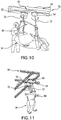
- Figures 9 and 10 depict particularly clearly how the motor units can tilt, leading them to remain generally aligned with the direction in which their respective strap elements 70, 72 are loaded.
- the motor units 52, 54 are able to tilt by 15 to 25 degrees from the horizontal, which has been found to be adequate.
- the skilled person will appreciate, though, that the angle to which the motor units 52 and 54 can be allowed to tilt can be different and could be greater or smaller than this, depending of the ultimate design of the apparatus and its specific usage.
- the trolley 60 may be provided in some embodiments with limit stops to limit the maximum degree of tilt.
- Figure 10 shows particularly clearly how the tilt of the motor units 52, 54 enables them to follow better the direction in which their respective straps 70, 72 are pulled and as a result enables the straps 70, 72 to remain better aligned with respect to their motor units.
- the motor units 52, 54 will generally tilt in the direction of the arrows in Figure 10 , in practice in a direction away from one another.
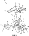
- the trolley 60 is formed of upper and lower support plate members 62, 64.
- the upper plate member 62 includes a base panel 100 of generally rectangular or square shape and having at opposing sides two upstanding panel walls 102, 104.
- the walls 102, 104 which are parallel to one another, carry three sets of wheel units 106, 108, 110, each having two wheels on a common axle and disposed on either side of their associated panel wall 102, 104.
- the sets of wheel units 106, 108 are disposed close to one another at one end of their respective panel wall 102, 104, while the third set of wheel units 110 is disposed at the other end of the panel walls 102, 104.
- the wheel sets 106-110 are asymmetric along the lengths of the panel walls 102,104.
- the lower support plate member 64 also comprises a base panel 120 which has a generally rectangular or square shape and which has at opposing sides upstanding side walls 122, 124, which extend beyond the ends of the base panel 120.
- the plate member 64 also includes upstanding end walls 126, 128 which are advantageously fixed to the side walls 122, 124, for example by welding, bonding or in any other manner.
- the upstanding walls 122-128 form a recess or chamber in the lower support member 64 for receiving a rotatable coupling member 150 described in further detail below.
- the lower support member 64 also includes first and second pivotable support elements 130, 132 which in this embodiment are elongate rectangular box sections and which are sized to fit snugly between the upstanding side walls 122, 124, as can be seen in particular in Figures 12 and 13 .
- the pivotable support members 130,132 are attached to the side walls 122,124 by an arrangement of dry polymer bushings 134 into which pivot pins 136 can pass, the latter being fixed to the support members 130,132 by bolts 138.
- These pins 136 fix the pivotable support members 130, 132 to the support member 64 in a manner in which they can rotate around an axis running though the opposing pivot pins 136, with the pivot pins 136 being solidary with the support members 130,132.
- the pivotable support members 130, 132 also include a fixing device, in this example a slot 140 and securing key 142.
- the motor units 52, 54 are fixed to the support member 130,132 from below, by suitable fixing members, suitable structures being immediately apparent to the skilled person.
- the rotatable coupling member 150 includes first and second concentric ring elements 152, 154 which are designed to be rotatable relative to one another, for instance by having an array of ball bearings therebetween, running in facing channels in the ring elements 152, 154. Any other rotary mechanism could be used.
- Each ring element 152, 154 is provided with a plurality of holes, preferably threaded bores, into which bolts 160, 162 can be fitted, such that one of the ring elements 106, 162 is fixed to one of the base panels 100, 120 and the other ring element is fixed to the other base panel.
- the upper and lower support members 62, 64 are therefore attached to one another in a manner in which they can rotate about a vertical axis, in a horizontal plane.
- the rotatable coupling member 150 preferably has a substantial diameter, at least 50% of the width of the trolley 60 and preferably large enough to fill the area within the upstanding walls 122-128. A large diameter gives the coupling member 60 greater strength and makes it able to withstand asymmetric forces better.
- the pivotable support members 130,132 and the upper and lower frame elements 62, 64 can usefully be made from sheets of metal or metal alloy.
- the structure taught herein allows the motor units 52, 54 to pivot freely around an axis passing through their suspension point, namely around the axis of the pivot pins 136. This enables the motor units 52, 54 to follow the loading direction and eliminate motor unit side loading.
- the pivoting of the motor units 52, 54 also effectively increases the horizontal distance of between the points of origin of the flexible load supporting straps 70, 72, that is at the point where they exit their associated motor unit 52, 54. This reduces the shear stress on a patient when in the reclined position. In other words, the effect of the pivoting motion of the motor units 52, 54 provides more room for the patient if needed.
- the structure taught herein can provide a compact device while maximizing patient room in the reclined position and as a result can minimize shear stress on the patient from the sling.
- the structure can also avoid the issue of side loading (of the type shown in Figure 6 ) when lifting very large patients in the reclined position, thereby reducing the risk of premature wear and failure.
Landscapes
- Health & Medical Sciences (AREA)
- Nursing (AREA)
- Life Sciences & Earth Sciences (AREA)
- Animal Behavior & Ethology (AREA)
- General Health & Medical Sciences (AREA)
- Public Health (AREA)
- Veterinary Medicine (AREA)
- Invalid Beds And Related Equipment (AREA)
Description
- The present disclosure claims priority to
US provisional patent application no. 62/080,909, filed on November 17, 2014 - The present disclosure relates to a patient ceiling lift assembly for use, for example, in a hospital or care home.
- Ceiling lifts for lifting and transporting patients have been in use for over twenty years. These types of patient lift are becoming more popular as they take up little space in a hospital or care home environment and are more efficient than floor lifts.
- A ceiling lift can be described as a motor unit able to move along one or more rails arranged as a rail system, fixed to the ceiling. A flexible member such as a strap extends from the motor unit and is attached to a spreader bar. A patient sling or harness is attached to the spreader bar. An electrically motorized mechanism in the motor unit allows the user to extend or shorten the strap so as to raise or lower the spreader bar and with this to raise or lower the sling and any patient carried in the sling. The combination of rail system, motor unit, spreader bar and sling is often referred to as a ceiling lift system.
- Some ceiling lift systems are said to be fixed (the motor unit is dedicated to one room) while others are said to be portable (the motor unit can move around from room to room).
- Over the last decades the size (weight & morphology) of patients has increased, causing manufacturers of ceiling lift systems to develop solutions which better address the handling challenges larger patients pose. The initial response from manufacturers was to increase the lifting capacity of their existing products. Since then, patient handling techniques were developed, industry standards were established and user (patient and care givers) needs were better understood. It appears that there was room for devices which could do more than just having a greater lifting capacity and be able to transfer a patient in a fixed seated position. Indeed, users were in the need of a product with greater versatility.
- One design adopted by manufacturers for handling patients of very large size (with a Body Mass Index above 40 or of weight above 160 kg, for example) has two motor units with two spreader bars which operate together. In one configuration, one of the motor units and its associated spreader bar supports/lifts the shoulder section of the patient, while the other motor unit and spreader bar supports/lifts the patient's leg section. A key benefit of such solution is the ability to provide a tilting function to sit or recline the patient during transfer, by creating a height difference between the spreader bars. Bringing the leg section spreader bar above the shoulder section spreader bar leads to a patient reclined position, while bringing the leg section spreader bar below the shoulder section spreader bar leads to a patient sitting position.
- A tilting function can increase patient comfort and reduce caregiver effort to transfer a patient. Although the above-described solutions for very large patients can provide significant benefits, they can sometimes have the drawback of being suitable only to such patient morphology. Care institutions face the challenge of making the care environment, typically the patient rooms, as versatile as possible when it comes to the range of patients they can handle. As a result the patient environment should be able to accommodate very large patients but also very small patients. Otherwise, a room dedicated for very large sized patients can often be unoccupied for long periods of time.
- Ceiling lift systems based on the use of two motor units and two spreader bars can be arranged to have the motor units able to move apart from one another, for example slidably located on a support rail, or can be fixed in position. While an arrangement which allows for the motor units to move apart can better accommodate a large patient, they can suffer from a loss of compactness of the apparatus and from loss of strength of the assembly. Fixed motor units can, however, only accommodate larger patients awkwardly.
- The present disclosure relates to an improved patient ceiling lift system.
- According to an aspect of the present disclosure, there is provided a patient ceiling lift system, including: first and second motor units; first and second tension support members each coupled to a respective one of the first and second motor units, each motor unit being operable to change an operative length of its associated strap element by extending or retracting the strap out of or into the motor unit, each strap element including a coupling for attachment to a patient sling; a support frame assembly to which the first and second motor units are attached, the support frame assembly including a coupling for a ceiling carrier system; wherein the support frame assembly includes first and second independent pivotable support members to which the first and second motor units are attached, whereby the motor units are able to pivot on the support frame and relative to one another.
- According to anther embodiment, there is provided a patient ceiling lift system that includes first and second motor units; first and second tension support members each coupled to a respective one of the first and second motor units. Each motor unit is operable to change the operative length of its associated tension support member element by extending or retracting the tension support member out of or into the motor unit. The motor units are attached to first and second independent pivotable support members of a support frame assembly which also includes a coupling for a ceiling carrier system. The motor units are able to pivot on the support frame and relative to one another, which enables the motor units to follow the loading direction on the tension support member and eliminate motor unit side loading. The pivoting of the motor units also effectively increases the horizontal distance of between the points of origin of the flexible load supporting tension support member, which reduces the shear stress on a patient when in the reclined position. The structure can also provide a compact device while maximizing patient room in the reclined position.
- The provision of a pivoting motion to the motor units enables them to turn in the direction of a pulling force on the straps, enabling them between to accommodate the spacing between the straps or other tension support members of a sling. This improves the operation of the motor units. Moreover, the arrangement can avoid the need to have motor units which are able to move apart, and can therefore contribute to a more compact system at reduced cost. Other embodiments combine the concept of tiltable motor units with a system which enables the distance between the motor units to be changed, for example by having the motor units mounted on a rail.
- In an embodiment, the pivotable support members are able to rotate by between 15 and 25 degrees. It has been found that such a range of pivoting meets the requirements of ceiling lift systems, although the range could be extended to greater pivoting angles should the need arise, for instance where the ceiling height is particularly low.
- Advantageously, in an embodiment the pivotable support members are rectangular or square section tubular closed end elements having one or more connection points for connection to the motor units. Elements of such a shape enable good fixation of the motor units to the support members and also provide significant strength to the support members. In an illustrative embodiment, the pivotable support members advantageously rotate about an axle at their closed ends.
- In an example embodiment, the support frame assembly includes first and second plate members disposed one over the other, the first plate member including the coupling for a ceiling carrier system and the pivotable support members being attached to the second plate member. In an embodiment, the first and second plate members are connected to one another by a rotatable coupling enabling the first and second frame members to rotate relative to one another. The rotatable coupling can include first and second concentric ring elements rotatably coupled to one another, the first ring element being fixed to the first plate member and the second ring element being fixed to the second plate member. Such a coupling can be made to have a significant diameter, which enables the coupling to support very heavy weights and also asymmetric weights, for instance when just one of the motor units is used to support a patient.
- In an embodiment, the first and second concentric ring elements have a diameter at least 50% of a width of the first and second plate members. They may, in practice, have a much greater diameter, typically just smaller than the width of the plate members.
- In an example embodiment, the first and second plate members each include a plurality of upstanding flange walls extending from a base plate element of the member. These walls contribute to the strength of the plate members and reduce their deformation when subjected to very heavy loads. The coupling for a ceiling carrier system is, in an embodiment, located on the upstanding flange walls of the first plate member.
- In an embodiment, the coupling advantageously comprises a series of wheel elements. In an example embodiment, the rail coupling includes at least three pairs of wheel elements.
- In an example embodiment the first motor unit is a leading motor unit and the second motor unit is a driven motor unit. Each wheel element may include first and second coaxially mounted wheels, which may be disposed on opposite sides of an upstanding flange wall of the support frame assembly.
- Other features and aspects of the disclosure herein will become apparent from the disclosure of the illustrative embodiments, which follows.
- Embodiments of the present disclosure are described below, by way of example only, with reference to the accompanying drawings, in which:
-
Figures 1 and 2 show an example of a prior art ceiling lift system, spreader bar and sling; -
Figure 3 shows an example of a double motor ceiling lift system; -
Figure 4 is a schematic diagram showing a double motor unit ceiling hoist system attached to a patient sling; -
Figures 5 and 6 shows the effect on the strap of one of the motor units caused by different sling configurations; -
Figures 7 to 11 depict an example embodiment of a ceiling lift system according to the teachings herein; -
Figure 12 is a perspective view of an embodiment of support trolley of the ceiling lift system ofFigures 7 to 11 ; -
Figure 13 is an enlarged view of a part of the support trolley ofFigure 12 ; -
Figure 14 is an exploded view of the support trolley ofFigure 12 ; and -
Figure 15 is an enlarged view of a part of the components of the support trolley ofFigure 14 . - Referring first to
Figure 1 , this shows a conventionalceiling lift system 10 which includes arail 12 that is fixed to the ceiling structure of a patient care facility, such as a hospital, care home or the like. Therail 12 includes a downwardly dependingchannel 14. Thesystem 10 may include a transmission, winding or coiling assembly, having for example amotor unit 16 which includes a wheel or roller (not shown) which runs within the downwardly dependingchannel 14 to allow themotor unit 16 to be moved in supported manner along therail 12, as is known in the art. - The
motor unit 16 is operatively associated with, coupled to and/or includes a tensile support member, such as a flexible element orstrap 18, which in practice is attached to a motorised spool or drum within themotor unit 16, and which can be unwound from the spool to lengthen thestrap 18 and wound on the spool to shorten thestrap 18, again in known manner. One skilled in the art would appreciate that one or more or any number of tensile support members may be operatively associated with, coupled to and/or form part of a motor unit to facilitate patient support. In one embodiment, the tensile support member is configured to be coilable about the drum or motorized spool ofmotor unit 16 and having sufficient tensile strength for lifting a patient. In an exemplary embodiment, the support member may be rigid in tension along its length yet permit motion in other directions to dynamically support a patient, inclusive of bariatric patients. Exemplary support members may include webbing, belts, rope, wire, cord, cable and chains. Thestrap 18 includes a coupler at its lower, free end, to which there can be attached aspreader bar 20, again of known form. The coupling can be any fastener, connector, attachment or securement mechanism suitable for connection tospreader bar 20. Thespreader bar 20 includes coupling points 22, which are spaced from one another and specifically at either end of thebar 20. The coupling points 22 act as attachments for asling 24, as shown inFigure 2 . Thesling 24 is provided with a plurality ofstraps sling 24 is held by thespreader bar 20 in an open condition to support a patient comfortably in thesling 24. These slings are well known in the art. - While a system as shown in
Figures 1 and 2 is suitable for lifting and transporting patients up to moderate sizes, heavier or larger patients cannot be carried by a simple system of this nature. In this regard, the apparatus ofFigure 3 is generally used. Theapparatus 30 includes twomotor units 16 which are attached to asupport unit 32, is coupled to therail 12, as in the example ofFigure 1 . Theapparatus 30 includes twospreader bars 20, each attached to arespective strap 18 of arespective motor unit 16. Themotor units 16 are spaced from one another so that onestrap 18 and its associatedspreader bar 20 can be located around the top of the patient's torso, whereas the other motor unit andspreader bar 20 is located around the patient's thigh position. Asling 34 includes pairs ofstraps sling 34 in a gently reclining position as shown in the example ofFigure 3 . - The
motor units 16 are operable to release and withdraw lengths ofstrap 18 such that the spreader bars 20 can be raised or lowered as required. For instance, thestraps 18 can be lengthened to lower the spreader bars 20 towards a patient reclining on a bed and then wound into themotor units 16 to raise the spreader bars 20 and thus to raise the patient while carried in thesling 34. Themotor units 18 are, for this purpose, controlled by a caregiver such as nurse, and are advantageously movable independently of one another when the patient is moved to different positions while suspended in thesling 34. For example, the patient can be held in a substantially reclining position as shown inFigure 3 or could be raised to a sitting position, by raising thespreader bar 20 at the torso end of the patient. - The patient
ceiling lift apparatus 30 shown inFigure 3 spaces themotor units 16 from one another in order to have the motor units positioned generally vertically above the spreader bars when the sling is in the patient reclining position. While this is suitable in the configuration shown, spacing themotor units 16 in this manner leads to a larger assembly and also one which is not optimal for asymmetric use, that is using asingle motor unit 16 only. -
Figure 4 shows anassembly 40 in which the twomotor units 16 are positioned adjacent one another and which can be seen provides a more compact assembly that the example shown inFigure 3 . The assembly can also be stronger and better able to support asymmetric loads, for instance when using a single motor unit to carry a patient. As a result of the positioning of themotor units 16 adjacent one another, thestrap elements 18 are also close to one another. While this does not generally cause a problem with a smaller patient or with a patient in an upright sitting position, it does cause problems with larger patients. With reference toFigure 5 , thestrap 18 can be seen extending from themotor unit 16 in a generally vertical orientation, as it is designed to do. On the other hand, with reference toFigure 6 , thestrap 16 can be seen extending at an angle to the vertical, as would occur when the assembly is supporting a sling/patient having greater distances between the two spreader bars, as can occur with a large patient and a patient in the reclining position. This imparts side stress on themotor unit 16, which it is not designed to withstand and which contributes to increased friction and wear. When themotor units 16 andstraps 18 are exposed to such stresses on a frequent or too numerous basis they can fail prematurely. Furthermore, the forces imparted to the sling will pull the sling to a closed position, causing shear stress on the patient, leading to patient discomfort. - An example embodiment of
ceiling lift assembly 50 is shown inFigures 7 to 12 . With reference to these Figures, theassembly 50 includes first andsecond motor units Figures 1 and3 to 6 , or any other known or suitable motor unit. Eachmotor unit strap element strap element strap element motor unit strap elements spreader bar assembly 80. Theassembly 80, in this example, includes two spreader bar yokes 82 connected together by a connection element 84. - The
assembly 50 also includes asupport trolley 60 which couples to aceiling rail system 66 and which is described in further detail below. Themotor units support trolley 60, specifically topivotable connection members pivotable connection members trolley 60, preferably about axes which are perpendicular to the longitudinal direction of the system, defined by the axis along which the twospreader bars 82 lie and in practice a head to toe direction of a patient. Thus, themotor units straps Figures 9 and10 depict particularly clearly how the motor units can tilt, leading them to remain generally aligned with the direction in which theirrespective strap elements motor units motor units trolley 60 may be provided in some embodiments with limit stops to limit the maximum degree of tilt. -
Figure 10 shows particularly clearly how the tilt of themotor units respective straps straps motor units Figure 10 , in practice in a direction away from one another. - Referring now to
Figures 12 to 15 , illustrated are details of thetrolley unit 60 of theassembly 50. Thetrolley 60 is formed of upper and lowersupport plate members upper plate member 62 includes abase panel 100 of generally rectangular or square shape and having at opposing sides twoupstanding panel walls walls wheel units panel wall wheel units respective panel wall wheel units 110 is disposed at the other end of thepanel walls - The lower
support plate member 64 also comprises a base panel 120 which has a generally rectangular or square shape and which has at opposing sidesupstanding side walls plate member 64 also includesupstanding end walls side walls lower support member 64 for receiving arotatable coupling member 150 described in further detail below. - The
lower support member 64 also includes first and secondpivotable support elements upstanding side walls Figures 12 and 13 . The pivotable support members 130,132 are attached to the side walls 122,124 by an arrangement ofdry polymer bushings 134 into which pivot pins 136 can pass, the latter being fixed to the support members 130,132 bybolts 138. Thesepins 136 fix thepivotable support members support member 64 in a manner in which they can rotate around an axis running though the opposing pivot pins 136, with the pivot pins 136 being solidary with the support members 130,132. Thepivotable support members slot 140 and securingkey 142. Themotor units - The
rotatable coupling member 150 includes first and secondconcentric ring elements ring elements ring element bolts ring elements base panels 100, 120 and the other ring element is fixed to the other base panel. The upper andlower support members rotatable coupling member 150 preferably has a substantial diameter, at least 50% of the width of thetrolley 60 and preferably large enough to fill the area within the upstanding walls 122-128. A large diameter gives thecoupling member 60 greater strength and makes it able to withstand asymmetric forces better. - The pivotable support members 130,132 and the upper and
lower frame elements - The structure taught herein allows the
motor units motor units motor units load supporting straps motor unit motor units - The structure taught herein can provide a compact device while maximizing patient room in the reclined position and as a result can minimize shear stress on the patient from the sling. The structure can also avoid the issue of side loading (of the type shown in
Figure 6 ) when lifting very large patients in the reclined position, thereby reducing the risk of premature wear and failure. - All optional and preferred features and modifications of the described embodiments and dependent claims are usable in all aspects of the illustrative embodiments taught herein. Furthermore, the individual features of the illustrative embodiments, as well as all optional and preferred features and modifications of the described embodiments are combinable and interchangeable with one another.
- While systems and methods have been described with reference to certain embodiments within this disclosure, one of ordinary skill in the art will recognize that additions, deletions and substitutions can be made within the scope of the appended claims.
Claims (14)
- A patient ceiling lift system, including:first (52) and second (54) motor units;first (70) and second (72) tension support members each coupled to a respective one of the first and second motor units, each motor unit being operable to change an operative length of its associated tension support member by extending or retracting the strap out of or into the motor unit, each tension support member including a coupling (82) for attachment to a patient sling;a support frame assembly (32, 60, 62, 64) to which the first and second motor units are attached, the support frame assembly including a coupling for a ceiling carrier system (66);wherein the support frame assembly (60) includes first (90) and second (92) independent pivotable support members to which the first and second motor units are attached, whereby the motor units are able to pivot on the support frame and relative to one another.
- A ceiling lift system according to claim 1, wherein the pivotable support members are able to rotate by between 15 and 25 degrees.
- A ceiling lift system according to any one of claims 1-2, wherein the pivotable support members are rectangular or square section tubular closed end elements having one or more connection points for connection to the motor units.
- A ceiling lift system according to any one of claims 1-3, wherein the pivotable support members rotate about an axle at their closed ends.
- A ceiling lift system according to any one of claims 1-4, wherein the support frame assembly includes first and second plate members disposed one over the other, the first plate member including the coupling for a ceiling carrier system and the pivotable support members being attached to the second plate member.
- A ceiling lift system according to claim 5, wherein the first and second plate members are connected to one another by a rotatable coupling enabling the first and second frame members to rotate relative to one another.
- A ceiling lift system according to claim 6, wherein the rotatable coupling includes first and second concentric ring elements rotatably coupled to one another, the first ring element being fixed to the first plate member and the second ring element being fixed to the second plate member.
- A ceiling lift system according to claim 7, wherein the first and second concentric ring elements have a diameter at least 50% of a width of the first and second plate members.
- A ceiling lift system according to any one of claims 5-8, wherein the first and second plate members each include a plurality of upstanding flange walls extending from a base plate element of the member.
- A ceiling lift system according to claim 9, wherein the coupling for a ceiling carrier system is located on the upstanding flange walls of the first plate member.
- A ceiling lift system according to any one of claims 1-10, wherein the coupling comprises a series of wheel elements.
- A ceiling lift system according to any one of claims 1-11, wherein the coupling includes at least three pairs of wheel elements.
- A ceiling lift system according to any one of claims 11-12, wherein each wheel element includes first and second coaxially mounted wheels.
- A ceiling lift system according to claim 13, wherein the first and second coaxially mounted wheels are disposed on opposite sides of an upstanding flange wall of the support frame assembly.
Applications Claiming Priority (2)
| Application Number | Priority Date | Filing Date | Title |
|---|---|---|---|
| US201462080909P | 2014-11-17 | 2014-11-17 | |
| PCT/CA2015/051198 WO2016077921A1 (en) | 2014-11-17 | 2015-11-17 | Tiltable patient ceiling lift assembly |
Publications (3)
| Publication Number | Publication Date |
|---|---|
| EP3220869A1 EP3220869A1 (en) | 2017-09-27 |
| EP3220869A4 EP3220869A4 (en) | 2018-08-01 |
| EP3220869B1 true EP3220869B1 (en) | 2019-09-25 |
Family
ID=56012990
Family Applications (1)
| Application Number | Title | Priority Date | Filing Date |
|---|---|---|---|
| EP15860173.2A Active EP3220869B1 (en) | 2014-11-17 | 2015-11-17 | Tiltable patient ceiling lift assembly |
Country Status (7)
| Country | Link |
|---|---|
| US (1) | US10238563B2 (en) |
| EP (1) | EP3220869B1 (en) |
| CA (1) | CA2968000C (en) |
| DK (1) | DK3220869T3 (en) |
| ES (1) | ES2754365T3 (en) |
| HK (1) | HK1244660B (en) |
| WO (1) | WO2016077921A1 (en) |
Families Citing this family (4)
| Publication number | Priority date | Publication date | Assignee | Title |
|---|---|---|---|---|
| HK1244660B (en) * | 2014-11-17 | 2020-05-22 | Arjohuntleigh Magog Inc. | Tiltable patient ceiling lift assembly |
| EP3233612B1 (en) * | 2014-12-17 | 2018-10-24 | Volvo Truck Corporation | Adjustable bunk and vehicle equipped with the same |
| EP3359107B1 (en) * | 2015-10-05 | 2020-06-17 | Amico Mobility Solutions Corp. | Patient lift system |
| EP3781110A1 (en) * | 2018-04-14 | 2021-02-24 | Adaptive Mobility LLC | Lift-transfer device with scoop-type stretcher |
Family Cites Families (20)
| Publication number | Priority date | Publication date | Assignee | Title |
|---|---|---|---|---|
| US3123224A (en) * | 1964-03-03 | Apparatus for lifting and transporting invalids | ||
| US3506985A (en) | 1968-07-15 | 1970-04-21 | Frederic F Lang | Apparatus for lifting and turning a bed patient |
| US3877089A (en) * | 1973-05-07 | 1975-04-15 | Mercy Lift Inc | Invalid lift apparatus |
| US4446587A (en) * | 1981-07-28 | 1984-05-08 | Jump Clarence E | Patient positioning device |
| US4627119A (en) * | 1985-01-22 | 1986-12-09 | Parasystems, Inc. | Apparatus to assist the disabled |
| DE4009283A1 (en) | 1990-03-22 | 1991-09-26 | Kreuzer F M K Gmbh | Device for raising bedridden patient to vertical position - has rectangular frame attached to vertical telescopic arm |
| JP2813871B2 (en) * | 1995-12-05 | 1998-10-22 | 芳夫 浅川 | Sick transporter |
| US5694654A (en) | 1996-05-01 | 1997-12-09 | Roy; Duane L. | Patient lifting and transfer system |
| US6711759B1 (en) * | 2002-11-25 | 2004-03-30 | Gary R. Kluckhuhn | Transfer system for an invalid patient |
| US7062804B2 (en) * | 2003-08-27 | 2006-06-20 | Rouse Samuel K | Patient movement system, method, and apparatus |
| US8407831B2 (en) | 2006-04-12 | 2013-04-02 | Ergonurse, Inc. | Patient positioning apparatus |
| EP1840073A1 (en) | 2006-03-29 | 2007-10-03 | Invacare International Sàrl | Overhead conveyor |
| EP2358323A1 (en) * | 2008-11-24 | 2011-08-24 | Hecare Systems APS | Handling system and method of arranging a person supported by a handling system |
| US8549679B2 (en) * | 2009-10-06 | 2013-10-08 | Jary Edward Tindall | Personal lifting device |
| US20140223660A1 (en) * | 2013-02-11 | 2014-08-14 | Handicare Ab | Patient lift device |
| US9757297B2 (en) * | 2014-02-03 | 2017-09-12 | Liko Research & Development Ab | Person lift system |
| WO2016077920A1 (en) * | 2014-11-17 | 2016-05-26 | Arjohuntleigh Magog Inc. | Configurable patient ceiling lift |
| HK1244660B (en) * | 2014-11-17 | 2020-05-22 | Arjohuntleigh Magog Inc. | Tiltable patient ceiling lift assembly |
| US10588806B2 (en) * | 2014-11-17 | 2020-03-17 | Arjohuntleigh Magog Inc. | Coupled spreader bar assembly for patient lift |
| PL3220872T3 (en) * | 2014-11-17 | 2023-03-20 | Arjo Ip Holding Ab | Ceiling lift tilt management system |
-
2015
- 2015-11-17 HK HK18104190.0A patent/HK1244660B/en unknown
- 2015-11-17 CA CA2968000A patent/CA2968000C/en active Active
- 2015-11-17 ES ES15860173T patent/ES2754365T3/en active Active
- 2015-11-17 DK DK15860173.2T patent/DK3220869T3/en active
- 2015-11-17 US US15/527,573 patent/US10238563B2/en active Active
- 2015-11-17 EP EP15860173.2A patent/EP3220869B1/en active Active
- 2015-11-17 WO PCT/CA2015/051198 patent/WO2016077921A1/en not_active Ceased
Non-Patent Citations (1)
| Title |
|---|
| None * |
Also Published As
| Publication number | Publication date |
|---|---|
| US20170354560A1 (en) | 2017-12-14 |
| EP3220869A1 (en) | 2017-09-27 |
| HK1244660B (en) | 2020-05-22 |
| ES2754365T3 (en) | 2020-04-17 |
| DK3220869T3 (en) | 2019-12-16 |
| US10238563B2 (en) | 2019-03-26 |
| CA2968000C (en) | 2023-03-07 |
| CA2968000A1 (en) | 2016-05-26 |
| EP3220869A4 (en) | 2018-08-01 |
| WO2016077921A1 (en) | 2016-05-26 |
Similar Documents
| Publication | Publication Date | Title |
|---|---|---|
| US8549679B2 (en) | Personal lifting device | |
| US11278460B2 (en) | Sling bar devices for person lifting systems and methods for operating sling bar devices | |
| EP2901997B1 (en) | Person lift system | |
| US10182955B2 (en) | Configurable patient ceiling lift | |
| AU2008303054B2 (en) | Improved patient lifting apparatus | |
| AU2012238880B2 (en) | Hoist apparatus | |
| CA2968000C (en) | Tiltable patient ceiling lift assembly | |
| HK1244660A1 (en) | Tiltable patient ceiling lift assembly | |
| US7290299B2 (en) | Device and method for positioning patients | |
| CA2967852C (en) | Coupled spreader bar assembly for patient lift | |
| US20200345569A1 (en) | Two-point, four points and multiple points lifting patient lifting robots | |
| KR101704998B1 (en) | Patient transfer apparatus | |
| HK1244663B (en) | Coupled spreader bar assembly for patient lift | |
| HK1244661B (en) | Configurable patient ceiling lift | |
| EP3409257A1 (en) | Linear actuator for patient lift |
Legal Events
| Date | Code | Title | Description |
|---|---|---|---|
| STAA | Information on the status of an ep patent application or granted ep patent |
Free format text: STATUS: THE INTERNATIONAL PUBLICATION HAS BEEN MADE |
|
| PUAI | Public reference made under article 153(3) epc to a published international application that has entered the european phase |
Free format text: ORIGINAL CODE: 0009012 |
|
| STAA | Information on the status of an ep patent application or granted ep patent |
Free format text: STATUS: REQUEST FOR EXAMINATION WAS MADE |
|
| 17P | Request for examination filed |
Effective date: 20170530 |
|
| AK | Designated contracting states |
Kind code of ref document: A1 Designated state(s): AL AT BE BG CH CY CZ DE DK EE ES FI FR GB GR HR HU IE IS IT LI LT LU LV MC MK MT NL NO PL PT RO RS SE SI SK SM TR |
|
| AX | Request for extension of the european patent |
Extension state: BA ME |
|
| DAV | Request for validation of the european patent (deleted) | ||
| DAX | Request for extension of the european patent (deleted) | ||
| A4 | Supplementary search report drawn up and despatched |
Effective date: 20180629 |
|
| RIC1 | Information provided on ipc code assigned before grant |
Ipc: A61G 7/10 20060101AFI20180625BHEP Ipc: A61G 7/14 20060101ALI20180625BHEP |
|
| REG | Reference to a national code |
Ref country code: HK Ref legal event code: DE Ref document number: 1244660 Country of ref document: HK |
|
| GRAP | Despatch of communication of intention to grant a patent |
Free format text: ORIGINAL CODE: EPIDOSNIGR1 |
|
| STAA | Information on the status of an ep patent application or granted ep patent |
Free format text: STATUS: GRANT OF PATENT IS INTENDED |
|
| INTG | Intention to grant announced |
Effective date: 20190430 |
|
| GRAS | Grant fee paid |
Free format text: ORIGINAL CODE: EPIDOSNIGR3 |
|
| GRAA | (expected) grant |
Free format text: ORIGINAL CODE: 0009210 |
|
| STAA | Information on the status of an ep patent application or granted ep patent |
Free format text: STATUS: THE PATENT HAS BEEN GRANTED |
|
| AK | Designated contracting states |
Kind code of ref document: B1 Designated state(s): AL AT BE BG CH CY CZ DE DK EE ES FI FR GB GR HR HU IE IS IT LI LT LU LV MC MK MT NL NO PL PT RO RS SE SI SK SM TR |
|
| REG | Reference to a national code |
Ref country code: GB Ref legal event code: FG4D |
|
| REG | Reference to a national code |
Ref country code: CH Ref legal event code: EP |
|
| REG | Reference to a national code |
Ref country code: AT Ref legal event code: REF Ref document number: 1183096 Country of ref document: AT Kind code of ref document: T Effective date: 20191015 |
|
| REG | Reference to a national code |
Ref country code: IE Ref legal event code: FG4D |
|
| REG | Reference to a national code |
Ref country code: DE Ref legal event code: R096 Ref document number: 602015038830 Country of ref document: DE |
|
| GRAT | Correction requested after decision to grant or after decision to maintain patent in amended form |
Free format text: ORIGINAL CODE: EPIDOSNCDEC |
|
| REG | Reference to a national code |
Ref country code: SE Ref legal event code: TRGR |
|
| REG | Reference to a national code |
Ref country code: DK Ref legal event code: T3 Effective date: 20191211 |
|
| RAP2 | Party data changed (patent owner data changed or rights of a patent transferred) |
Owner name: ARJOHUNTLEIGH MAGOG INC. |
|
| REG | Reference to a national code |
Ref country code: NL Ref legal event code: FP |
|
| PG25 | Lapsed in a contracting state [announced via postgrant information from national office to epo] |
Ref country code: BG Free format text: LAPSE BECAUSE OF FAILURE TO SUBMIT A TRANSLATION OF THE DESCRIPTION OR TO PAY THE FEE WITHIN THE PRESCRIBED TIME-LIMIT Effective date: 20191225 Ref country code: NO Free format text: LAPSE BECAUSE OF FAILURE TO SUBMIT A TRANSLATION OF THE DESCRIPTION OR TO PAY THE FEE WITHIN THE PRESCRIBED TIME-LIMIT Effective date: 20191225 Ref country code: LT Free format text: LAPSE BECAUSE OF FAILURE TO SUBMIT A TRANSLATION OF THE DESCRIPTION OR TO PAY THE FEE WITHIN THE PRESCRIBED TIME-LIMIT Effective date: 20190925 Ref country code: FI Free format text: LAPSE BECAUSE OF FAILURE TO SUBMIT A TRANSLATION OF THE DESCRIPTION OR TO PAY THE FEE WITHIN THE PRESCRIBED TIME-LIMIT Effective date: 20190925 Ref country code: HR Free format text: LAPSE BECAUSE OF FAILURE TO SUBMIT A TRANSLATION OF THE DESCRIPTION OR TO PAY THE FEE WITHIN THE PRESCRIBED TIME-LIMIT Effective date: 20190925 |
|
| REG | Reference to a national code |
Ref country code: LT Ref legal event code: MG4D |
|
| PG25 | Lapsed in a contracting state [announced via postgrant information from national office to epo] |
Ref country code: GR Free format text: LAPSE BECAUSE OF FAILURE TO SUBMIT A TRANSLATION OF THE DESCRIPTION OR TO PAY THE FEE WITHIN THE PRESCRIBED TIME-LIMIT Effective date: 20191226 Ref country code: LV Free format text: LAPSE BECAUSE OF FAILURE TO SUBMIT A TRANSLATION OF THE DESCRIPTION OR TO PAY THE FEE WITHIN THE PRESCRIBED TIME-LIMIT Effective date: 20190925 Ref country code: RS Free format text: LAPSE BECAUSE OF FAILURE TO SUBMIT A TRANSLATION OF THE DESCRIPTION OR TO PAY THE FEE WITHIN THE PRESCRIBED TIME-LIMIT Effective date: 20190925 |
|
| REG | Reference to a national code |
Ref country code: AT Ref legal event code: MK05 Ref document number: 1183096 Country of ref document: AT Kind code of ref document: T Effective date: 20190925 |
|
| REG | Reference to a national code |
Ref country code: ES Ref legal event code: FG2A Ref document number: 2754365 Country of ref document: ES Kind code of ref document: T3 Effective date: 20200417 |
|
| PG25 | Lapsed in a contracting state [announced via postgrant information from national office to epo] |
Ref country code: PT Free format text: LAPSE BECAUSE OF FAILURE TO SUBMIT A TRANSLATION OF THE DESCRIPTION OR TO PAY THE FEE WITHIN THE PRESCRIBED TIME-LIMIT Effective date: 20200127 Ref country code: AL Free format text: LAPSE BECAUSE OF FAILURE TO SUBMIT A TRANSLATION OF THE DESCRIPTION OR TO PAY THE FEE WITHIN THE PRESCRIBED TIME-LIMIT Effective date: 20190925 Ref country code: AT Free format text: LAPSE BECAUSE OF FAILURE TO SUBMIT A TRANSLATION OF THE DESCRIPTION OR TO PAY THE FEE WITHIN THE PRESCRIBED TIME-LIMIT Effective date: 20190925 Ref country code: EE Free format text: LAPSE BECAUSE OF FAILURE TO SUBMIT A TRANSLATION OF THE DESCRIPTION OR TO PAY THE FEE WITHIN THE PRESCRIBED TIME-LIMIT Effective date: 20190925 Ref country code: PL Free format text: LAPSE BECAUSE OF FAILURE TO SUBMIT A TRANSLATION OF THE DESCRIPTION OR TO PAY THE FEE WITHIN THE PRESCRIBED TIME-LIMIT Effective date: 20190925 Ref country code: RO Free format text: LAPSE BECAUSE OF FAILURE TO SUBMIT A TRANSLATION OF THE DESCRIPTION OR TO PAY THE FEE WITHIN THE PRESCRIBED TIME-LIMIT Effective date: 20190925 |
|
| PG25 | Lapsed in a contracting state [announced via postgrant information from national office to epo] |
Ref country code: IS Free format text: LAPSE BECAUSE OF FAILURE TO SUBMIT A TRANSLATION OF THE DESCRIPTION OR TO PAY THE FEE WITHIN THE PRESCRIBED TIME-LIMIT Effective date: 20200224 Ref country code: CZ Free format text: LAPSE BECAUSE OF FAILURE TO SUBMIT A TRANSLATION OF THE DESCRIPTION OR TO PAY THE FEE WITHIN THE PRESCRIBED TIME-LIMIT Effective date: 20190925 Ref country code: SM Free format text: LAPSE BECAUSE OF FAILURE TO SUBMIT A TRANSLATION OF THE DESCRIPTION OR TO PAY THE FEE WITHIN THE PRESCRIBED TIME-LIMIT Effective date: 20190925 Ref country code: SK Free format text: LAPSE BECAUSE OF FAILURE TO SUBMIT A TRANSLATION OF THE DESCRIPTION OR TO PAY THE FEE WITHIN THE PRESCRIBED TIME-LIMIT Effective date: 20190925 |
|
| REG | Reference to a national code |
Ref country code: DE Ref legal event code: R097 Ref document number: 602015038830 Country of ref document: DE |
|
| REG | Reference to a national code |
Ref country code: CH Ref legal event code: PL |
|
| PG2D | Information on lapse in contracting state deleted |
Ref country code: IS |
|
| PG25 | Lapsed in a contracting state [announced via postgrant information from national office to epo] |
Ref country code: LI Free format text: LAPSE BECAUSE OF NON-PAYMENT OF DUE FEES Effective date: 20191130 Ref country code: LU Free format text: LAPSE BECAUSE OF NON-PAYMENT OF DUE FEES Effective date: 20191117 Ref country code: CH Free format text: LAPSE BECAUSE OF NON-PAYMENT OF DUE FEES Effective date: 20191130 Ref country code: MC Free format text: LAPSE BECAUSE OF FAILURE TO SUBMIT A TRANSLATION OF THE DESCRIPTION OR TO PAY THE FEE WITHIN THE PRESCRIBED TIME-LIMIT Effective date: 20190925 Ref country code: IS Free format text: LAPSE BECAUSE OF FAILURE TO SUBMIT A TRANSLATION OF THE DESCRIPTION OR TO PAY THE FEE WITHIN THE PRESCRIBED TIME-LIMIT Effective date: 20200126 |
|
| PLBE | No opposition filed within time limit |
Free format text: ORIGINAL CODE: 0009261 |
|
| STAA | Information on the status of an ep patent application or granted ep patent |
Free format text: STATUS: NO OPPOSITION FILED WITHIN TIME LIMIT |
|
| 26N | No opposition filed |
Effective date: 20200626 |
|
| PG25 | Lapsed in a contracting state [announced via postgrant information from national office to epo] |
Ref country code: IE Free format text: LAPSE BECAUSE OF NON-PAYMENT OF DUE FEES Effective date: 20191117 |
|
| PG25 | Lapsed in a contracting state [announced via postgrant information from national office to epo] |
Ref country code: SI Free format text: LAPSE BECAUSE OF FAILURE TO SUBMIT A TRANSLATION OF THE DESCRIPTION OR TO PAY THE FEE WITHIN THE PRESCRIBED TIME-LIMIT Effective date: 20190925 |
|
| PG25 | Lapsed in a contracting state [announced via postgrant information from national office to epo] |
Ref country code: CY Free format text: LAPSE BECAUSE OF FAILURE TO SUBMIT A TRANSLATION OF THE DESCRIPTION OR TO PAY THE FEE WITHIN THE PRESCRIBED TIME-LIMIT Effective date: 20190925 |
|
| PG25 | Lapsed in a contracting state [announced via postgrant information from national office to epo] |
Ref country code: HU Free format text: LAPSE BECAUSE OF FAILURE TO SUBMIT A TRANSLATION OF THE DESCRIPTION OR TO PAY THE FEE WITHIN THE PRESCRIBED TIME-LIMIT; INVALID AB INITIO Effective date: 20151117 Ref country code: MT Free format text: LAPSE BECAUSE OF FAILURE TO SUBMIT A TRANSLATION OF THE DESCRIPTION OR TO PAY THE FEE WITHIN THE PRESCRIBED TIME-LIMIT Effective date: 20190925 |
|
| PG25 | Lapsed in a contracting state [announced via postgrant information from national office to epo] |
Ref country code: TR Free format text: LAPSE BECAUSE OF FAILURE TO SUBMIT A TRANSLATION OF THE DESCRIPTION OR TO PAY THE FEE WITHIN THE PRESCRIBED TIME-LIMIT Effective date: 20190925 |
|
| PG25 | Lapsed in a contracting state [announced via postgrant information from national office to epo] |
Ref country code: MK Free format text: LAPSE BECAUSE OF FAILURE TO SUBMIT A TRANSLATION OF THE DESCRIPTION OR TO PAY THE FEE WITHIN THE PRESCRIBED TIME-LIMIT Effective date: 20190925 |
|
| P01 | Opt-out of the competence of the unified patent court (upc) registered |
Effective date: 20230603 |
|
| PGFP | Annual fee paid to national office [announced via postgrant information from national office to epo] |
Ref country code: NL Payment date: 20251119 Year of fee payment: 11 |
|
| PGFP | Annual fee paid to national office [announced via postgrant information from national office to epo] |
Ref country code: DE Payment date: 20251119 Year of fee payment: 11 |
|
| PGFP | Annual fee paid to national office [announced via postgrant information from national office to epo] |
Ref country code: GB Payment date: 20251121 Year of fee payment: 11 |
|
| PGFP | Annual fee paid to national office [announced via postgrant information from national office to epo] |
Ref country code: IT Payment date: 20251125 Year of fee payment: 11 Ref country code: DK Payment date: 20251125 Year of fee payment: 11 |
|
| PGFP | Annual fee paid to national office [announced via postgrant information from national office to epo] |
Ref country code: FR Payment date: 20251126 Year of fee payment: 11 |
|
| PGFP | Annual fee paid to national office [announced via postgrant information from national office to epo] |
Ref country code: BE Payment date: 20251119 Year of fee payment: 11 |
|
| PGFP | Annual fee paid to national office [announced via postgrant information from national office to epo] |
Ref country code: SE Payment date: 20251119 Year of fee payment: 11 |
|
| PGFP | Annual fee paid to national office [announced via postgrant information from national office to epo] |
Ref country code: ES Payment date: 20251229 Year of fee payment: 11 |