EP3220798B1 - Endocoupler with induction coupling - Google Patents
Endocoupler with induction coupling Download PDFInfo
- Publication number
- EP3220798B1 EP3220798B1 EP15801628.7A EP15801628A EP3220798B1 EP 3220798 B1 EP3220798 B1 EP 3220798B1 EP 15801628 A EP15801628 A EP 15801628A EP 3220798 B1 EP3220798 B1 EP 3220798B1
- Authority
- EP
- European Patent Office
- Prior art keywords
- endocoupler
- induction coupling
- rotary
- coil
- endoscopic
- Prior art date
- Legal status (The legal status is an assumption and is not a legal conclusion. Google has not performed a legal analysis and makes no representation as to the accuracy of the status listed.)
- Active
Links
Images



Classifications
-
- A—HUMAN NECESSITIES
- A61—MEDICAL OR VETERINARY SCIENCE; HYGIENE
- A61B—DIAGNOSIS; SURGERY; IDENTIFICATION
- A61B1/00—Instruments for performing medical examinations of the interior of cavities or tubes of the body by visual or photographical inspection, e.g. endoscopes; Illuminating arrangements therefor
- A61B1/00002—Operational features of endoscopes
- A61B1/00011—Operational features of endoscopes characterised by signal transmission
- A61B1/00016—Operational features of endoscopes characterised by signal transmission using wireless means
-
- A—HUMAN NECESSITIES
- A61—MEDICAL OR VETERINARY SCIENCE; HYGIENE
- A61B—DIAGNOSIS; SURGERY; IDENTIFICATION
- A61B1/00—Instruments for performing medical examinations of the interior of cavities or tubes of the body by visual or photographical inspection, e.g. endoscopes; Illuminating arrangements therefor
- A61B1/00002—Operational features of endoscopes
- A61B1/00025—Operational features of endoscopes characterised by power management
- A61B1/00027—Operational features of endoscopes characterised by power management characterised by power supply
- A61B1/00029—Operational features of endoscopes characterised by power management characterised by power supply externally powered, e.g. wireless
-
- A—HUMAN NECESSITIES
- A61—MEDICAL OR VETERINARY SCIENCE; HYGIENE
- A61B—DIAGNOSIS; SURGERY; IDENTIFICATION
- A61B1/00—Instruments for performing medical examinations of the interior of cavities or tubes of the body by visual or photographical inspection, e.g. endoscopes; Illuminating arrangements therefor
- A61B1/00112—Connection or coupling means
- A61B1/00121—Connectors, fasteners and adapters, e.g. on the endoscope handle
- A61B1/00126—Connectors, fasteners and adapters, e.g. on the endoscope handle optical, e.g. for light supply cables
-
- A—HUMAN NECESSITIES
- A61—MEDICAL OR VETERINARY SCIENCE; HYGIENE
- A61B—DIAGNOSIS; SURGERY; IDENTIFICATION
- A61B1/00—Instruments for performing medical examinations of the interior of cavities or tubes of the body by visual or photographical inspection, e.g. endoscopes; Illuminating arrangements therefor
- A61B1/04—Instruments for performing medical examinations of the interior of cavities or tubes of the body by visual or photographical inspection, e.g. endoscopes; Illuminating arrangements therefor combined with photographic or television appliances
-
- A—HUMAN NECESSITIES
- A61—MEDICAL OR VETERINARY SCIENCE; HYGIENE
- A61B—DIAGNOSIS; SURGERY; IDENTIFICATION
- A61B1/00—Instruments for performing medical examinations of the interior of cavities or tubes of the body by visual or photographical inspection, e.g. endoscopes; Illuminating arrangements therefor
- A61B1/06—Instruments for performing medical examinations of the interior of cavities or tubes of the body by visual or photographical inspection, e.g. endoscopes; Illuminating arrangements therefor with illuminating arrangements
- A61B1/0661—Endoscope light sources
- A61B1/0684—Endoscope light sources using light emitting diodes [LED]
-
- A—HUMAN NECESSITIES
- A61—MEDICAL OR VETERINARY SCIENCE; HYGIENE
- A61B—DIAGNOSIS; SURGERY; IDENTIFICATION
- A61B1/00—Instruments for performing medical examinations of the interior of cavities or tubes of the body by visual or photographical inspection, e.g. endoscopes; Illuminating arrangements therefor
- A61B1/04—Instruments for performing medical examinations of the interior of cavities or tubes of the body by visual or photographical inspection, e.g. endoscopes; Illuminating arrangements therefor combined with photographic or television appliances
- A61B1/042—Instruments for performing medical examinations of the interior of cavities or tubes of the body by visual or photographical inspection, e.g. endoscopes; Illuminating arrangements therefor combined with photographic or television appliances characterised by a proximal camera, e.g. a CCD camera
Definitions
- the present application relates generally to endoscopic systems and methods, and more specifically to systems and methods of providing wireless power transmission from a camera head to one or more solid-state light sources housed in an endoscopic device.
- endoscopic systems and methods to inspect regions within a patient's body during surgical, diagnostic, and/or other medical procedures.
- a surgeon may employ an endoscopic system to inspect a patient's abdominal or pelvic cavity during a laparoscopic procedure, or to inspect a patient's thoracic or chest cavity during a thoracoscopic procedure.
- Such an endoscopic system may be employed in conjunction with surgical instruments such as forceps, scissors, probes, etc., to perform such a laparoscopic or thoracoscopic procedure through a small incision made in the patient's body, avoiding the need to open the patient's abdomen or chest. In this way, the patient's pain and/or discomfort due to the medical procedure, as well as the patient's recovery time, can be reduced.
- a conventional endoscopic system typically includes a camera head, an endocoupler, an endoscopic device, a light source, and a light cable.
- the endocoupler mechanically and optically couples the camera head to the endoscopic device, and the light cable connects the light source to the endoscopic device.
- the endoscopic device typically includes an elongated insertion tube that extends from the endocoupler to a distal end of the endoscopic device, as well as an optical fiber bundle that provides an optical path for directing light energy produced by the light source to the distal end of the endoscopic device.
- US 2006/116550 A1 describes an endoscope system in which an endoscope can be cleaned and sterilized more easily.
- the endoscope system comprising an endoscope having an inserting portion inserted in the body cavity, which is re-used by cleaning and sterilizing the inserting portion after ending the examination and treatment.
- US 2006/171693 A1 describes an endoscope with integrated light source.
- An LED based light source unit for an endoscopic imaging system produces illumination for a camera through an endoscope.
- the light source unit includes an array of LEDs mounted to a thermally conductive substrate.
- US 2011/018988 A1 describes endoscopic imaging system includes an endoscope.
- the described endoscopic imaging system includes an endoscope, a light source to transmit light through illumination channels in the endoscope, and an imaging unit to receive images of a region of interest that are formed at a tip of the endoscope that is inserted into the region.
- the components of the system are freely attachable and detachable from each other.
- US 2011/193948 A1 describes an endoscope video system.
- the system including an endoscope and a detachable camera head.
- the endoscope is provided with a transponder/transceiver and the detachable camera head is provided with a corresponding transponder/transceiver such that electrical power is transmitted from the camera head to the endoscope.
- the conventional endoscopic system described above has drawbacks, however, due atleast to the low efficiency and high power of the light source.
- a light source is typically a lamp that can require as much as 300 Watts of power or more in order to deliver about 1 Watt of light to the distal end of the endoscopic device, resulting in an efficiency of about 0.3%.
- the light source in combination with the light cable can be bulky and can add needless clutter to the surgical suite, as we]) as significantly increase the overall cost of the endoscopic system.
- endoscopic systems and methods that provide wireless power transmission from a camera head to at least one solid-state light source housed in an endoscopic device.
- the disclosed endoscopic systems and methods employ a multi-stage electromagnetic induction coupling mechanism that can wirelessly transfer power from the camera head to an endocoupler, as well as from the endocoupler to the solid-state light source, while allowing axial rotational motion of at least the camera head, the endocoupler, and/or the endoscopic device relative to one another.
- an exemplary endoscopic system includes a camera head, an endoscopic device, and an endocoupler that couples the camera head to the endoscopic device.
- the camera head is coupled to a proximal region of the endocoupler, and the endoscopic device is coupled to a distal region of the endocoupler.
- the endoscopic device can be a direct-view endoscope.
- the endoscopic device includes an elongated insertion tube, an illumination post housing, and an optical fiber bundle.
- the elongated insertion tube which can be rigid or flexible, extends from about the distal region of the endocoupler to a distal end section of the endoscopic device.
- the illumination post housing can house at least one solid-state light source.
- the solid-state light source can be a light-emitting diode (LED).
- the optical fiber bundle of the elongated insertion tube provides an optical path for directing light energy produced by the solid-state light source to the distal end section of the endoscopic device.
- the endoscopic system further includes a multi-stage electromagnetic induction coupling mechanism that can wirelessly transfer power from the camera head to the endocoupler, as well as from the endocoupler to the solid-state light source housed in the illumination post housing, while allowing axial rotational motion of at least the camera head, the endocoupler, and/or the endoscopic device relative to one another.
- the multi-stage electromagnetic induction coupling mechanism includes at least a first rotary induction coupling stage and a second rotary induction coupling stage. The first rotary induction coupling stage is disposed between the camera head and the endocoupler at or near the proximal region of the endocoupler.
- the second rotary induction coupling stage is disposed between the endocoupler and the endoscopic device at or near the distal region of the endocoupler.
- the first and second rotary induction coupling stages can each include a first coil/ferrite assembly that has a magnetic field generating coil wound around a first ferrite core, and a second coil/ferrite assembly that has a magnetic field capturing coil wound around a second ferrite core.
- the first and second coil/ferrite assemblies included in the first rotary induction coupling stage can be implemented as a rotary power transfer device, such as a rotary transformer.
- the first rotary induction coupling stage can further include a first rotary attachment mechanism, such as a threaded mount, for rotatably attaching the endocoupler to the camera head.
- a first rotary attachment mechanism such as a threaded mount
- the first and second coil/ferrite assemblies included in the second rotary induction coupling stage can likewise be implemented as a rotary power transfer device, such as a rotary transformer.
- the second rotary induction coupling stage can further include a second rotary attachment mechanism, such as a rotary joint, for rotatably attaching the endocoupler to the endoscopic device.
- an endoscopic system in an exemplary mode of operation, includes a camera head, an endoscopic device, an endocoupler coupling the camera head to the endoscopic device, a first rotary induction coupling stage disposed between the camera head and the endocoupler, and a second rotary induction coupling stage disposed between the endocoupler and the endoscopic device, which houses at least one solid-state light source.
- Power is provided, by the camera head, for powering the solid-state light source by providing a first alternating current (also referred to herein as the "first AC current") to a first coil/ferrite assembly within the first rotary induction coupling stage, thereby causing a first magnetic field to be generated by the first coil/ferrite assembly of the first rotary induction coupling stage.
- the first magnetic field generated by the first coil/ferrite assembly of the first rotary induction coupling stage is captured by a second coil/ferrite assembly within the first rotary induction coupling stage, thereby causing a second alternating current (also referred to herein as the "second AC current") to be induced in the second coil/ferrite assembly of the first rotary induction coupling stage.
- the second AC current is provided to a first coil/ferrite assembly within the second rotary induction coupling stage, thereby causing a second magnetic field to be generated by the first coil/ferrite assembly of the second rotary induction coupling stage.
- the second magnetic field generated by the first coil/ferrite assembly of the second rotary induction coupling stage is captured by a second coil/ferrite assembly within the second rotary induction coupling stage, thereby causing a third alternating current (also referred to herein as the "third AC current") to be induced in the second coil/ferrite assembly of the second rotary induction coupling stage.
- the third AC current is converted to a direct current (also referred to herein as the "DC current”), which is provided for powering the solid-state light source housed in the illumination post housing of the endoscopic device.
- the endoscopic device Having powered the solid-state light source, the endoscopic device is rotated, by a user, about its axis at the second rotary induction coupling stage in order to change the orientation of a distal end section of the endoscopic device, while maintaining the transfer of power by the second rotary induction coupling stage from the endocoupler to the solid-state light source housed in the endoscopic device.
- a focusing ring assembly implemented in the endocoupler is rotated, by the user, about its axis at the first rotary induction coupling stage in order to adjust focusing optics contained in the endocoupler and/or the camera head, while further maintaining the transfer of power by the first rotary induction coupling stage from the camera head to the endocoupler, and ultimately to the solid-state light source.
- an endoscopic system that includes a camera head, an endoscopic device, an endocoupler coupling the camera head to the endoscopic device, a first rotary induction coupling stage disposed between the camera head and the endocoupler, and at least a second rotary induction coupling stage disposed between the endocoupler and the endoscopic device
- a user e.g., a surgeon or other medical professional
- a solid-state light source e.g., an LED
- Endoscopic systems and methods are disclosed that provide wireless power transmission from a camera head to at least one solid-state light source housed in an endoscopic device.
- the disclosed endoscopic systems and methods employ a multi-stage electromagnetic induction coupling mechanism that can wirelessly transfer power from the camera head to an endocoupler, as well as from the endocoupler to the solid-state light source, while allowing axial rotational motion of at least the camera head, the endocoupler, and/or the endoscopic device relative to one another.
- FIG. 1 depicts an illustrative embodiment of an exemplary endoscopic system 100, in accordance with the present application.
- the endoscopic system 100 includes a camera head 106, an endoscopic device 102, and an endocoupler 104 configured to couple the camera head 106 to the endoscopic device 102.
- a surgeon or other medical professional may employ the endoscopic system 100 to inspect a region within a patient's body during a laparoscopic procedure, a thoracoscopic procedure, or any other suitable surgical, diagnostic, or other medical procedure.
- the endoscopic device 102 includes an elongated insertion tube 108, an eyepiece section 110, and an illumination post housing 112 for housing at least one solid-state light source (e.g., a solid-state light source 513; see FIG. 5a ).
- the endocoupler 104 includes a focusing ring 114 of a focus assembly (e.g., a focus assembly 514; see FIG. 5a ) for adjusting focusing optics ( e.g., at least one lens 218; see FIG. 2 ) contained in the endocoupler 104 and/or the camera head 106.
- the endocoupler 104 can project an image viewed through the eyepiece section 110 of the endoscopic device 102 onto an imaging sensor of the camera head 106.
- the camera head 106 is coupled to a proximal region 118 of the endocoupler 104
- the endoscopic device 102 is coupled to a distal region 116 of the endocoupler 104.
- the endoscopic device 102 can be a direct-view endoscope, or any other suitable endoscope.
- the elongated insertion tube 108 which can be rigid or flexible, extends from the eyepiece section 110 to a distal end section 120 of the endoscopic device 102.
- the solid-state light source 513 see FIG.
- the elongated insertion tube 108 can include an optical fiber bundle (e.g ., an optical fiber bundle 521; see FIG. 5a ) in order to provide an optical path for directing light energy produced by the solid-state light source to the distal end section 120 of the endoscopic device 102.
- an optical fiber bundle e.g ., an optical fiber bundle 521; see FIG. 5a
- the disclosed endoscopic system 100 further includes a multi-stage electromagnetic induction coupling mechanism that can wirelessly transfer power from the camera head 106 to the endocoupler 104, as well as from the endocoupler 104 to the solid-state light source housed in the illumination post housing 112, while allowing rotational motion, about an axis 122, of at least the camera head 106, the endocoupler 104, and/or the endoscopic device 102 relative to one another.
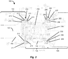
- the multi-stage electromagnetic induction coupling mechanism can include at least a first rotary induction coupling stage 202 and a second rotary induction coupling stage 204.
- the first rotary induction coupling stage 202 is disposed between the camera head 106 and the endocoupler 104 at or near the proximal region 118 of the endocoupler 104.
- the second rotary induction coupling stage 204 is disposed between the endocoupler 104 and the endoscopic device 102 at or near the distal region 116 of the endocoupler 104.
- the first rotary induction coupling stage 202 can include a first coil/ferrite assembly (not numbered) that has a magnetic field generating coil 206 wound around a ferrite core 207, and a second coil/ferrite assembly (not numbered) that has a magnetic field capturing coil 208 wound around a ferrite core 209.
- the first coil/ferrite assembly and the second coil/ferrite assembly of the first rotary induction coupling stage 202 are disposed longitudinally about the axis 122 of the endoscopic system 100.
- the first and second coil/ferrite assemblies of the first rotary induction coupling stage 202 can be implemented as a rotary transformer or any other suitable rotary power transfer device.
- the first and second coil/ferrite assemblies of the first rotary induction coupling stage 202 are implemented as a rotary transformer, one of the coil/ferrite assemblies can have a fixed coil, while the other coil/ferrite assembly has a rotatable coil.
- the first rotary induction coupling stage 202 can further include a threaded mount 220, such as a C-mount or any other suitable rotary attachment mechanism, for use in rotatably attaching the endocoupler 104 to the camera head 106.
- the second rotary induction coupling stage 204 of the endoscopic system 100 can include a first coil/ferrite assembly (not numbered) that has a magnetic field generating coil 210 wound around a ferrite core 215, and a second coil/ferrite assembly (not numbered) that has a magnetic field capturing coil 212 wound around a ferrite core 213.
- the first coil/ferrite assembly and the second coil/ferrite assembly of the second rotary induction coupling stage 204 are disposed longitudinally about the axis 122 of the endoscopic system 100.
- the first and second coil/ferrite assemblies of the second rotary induction coupling stage 204 can be implemented as a rotary transformer or any other suitable rotary power transfer device.
- the first and second coil/ferrite assemblies of the second rotary induction coupling stage 204 are implemented as a rotary transformer, one of the coil/ferrite assemblies can have a fixed coil, while the other coil/ferrite assembly has a rotatable coil.
- the second rotary induction coupling stage 204 can further include a rotary joint 211 or any other suitable rotary attachment mechanism, for use in rotatably attaching the endocoupler 104 to the endoscopic device 102.
- an alternating current (AC) source (also referred to herein as the "AC current source") (e.g., an AC current source 616; see FIG. 6 ) provides, via a first conductor disposed in a channel 222, a first AC current to the first coil/ferrite assembly of the first rotary induction coupling stage 202, causing a first magnetic field to be generated by the magnetic field generating coil 206.
- the magnetic field capturing coil 208 included in the second coil/ferrite assembly of the first rotary induction coupling stage 202 captures the first magnetic field generated by the magnetic field generating coil 206, causing a second AC current to be induced in the magnetic field capturing coil 208.
- a second conductor disposed in a channel 216 provides the second AC current to the first coil/ferrite assembly of the second rotary induction coupling stage 204, causing a second magnetic field to be generated by the magnetic field generating coil 210.
- the magnetic field capturing coil 212 included in the second coil/ferrite assembly of the second rotary induction coupling stage 204 captures the second magnetic field generated by the magnetic field generating coil 210, causing a third AC current to be induced in the magnetic field capturing coil 212.
- a third conductor disposed in a channel 214 provides the third AC current to a rectifier circuit (e.g., a rectifier circuit 523; see FIG.
- the endoscopic device 102 can be rotated, by a user (e.g., a surgeon or other medical professional), about the axis 122 at the second rotary induction coupling stage 204 in order to change the orientation of the distal end section 120 of the endoscopic device 102, while maintaining the transfer of power by the first and second coil/ferrite assemblies (e.g.
- the focusing ring 114 of the focus assembly can be rotated, by the user, about the axis 122 at the first rotary induction coupling stage 202 in order to adjust the focusing optics contained in the endocoupler 104 and/or the camera head 106, while further maintaining the transfer of power by the first and second coil/ferrite assemblies ( e.g ., another rotary transformer) of the first rotary induction coupling stage 202 from the camera head 106 to the endocoupler 104.
- the first and second coil/ferrite assemblies e.g ., another rotary transformer
- FIG. 3 depicts a first alternative embodiment of the endoscopic system 100 of FIG. 1 .
- an endoscopic system 300 includes a camera head 306, an endoscopic device 302, and an endocoupler 304 configured to couple the camera head 306 to the endoscopic device 302.
- the endoscopic device 302 includes an eyepiece section 310.
- the endocoupler 104 includes a focusing ring 314 of a focus assembly for adjusting focusing optics contained in the endocoupler 304 and/or the camera head 306.
- the endoscopic system 300 further includes a multi-stage electromagnetic induction coupling mechanism that can wirelessly transfer power from the camera head 306 to the endocoupler 304, as well as from the endocoupler 304 to a solid-state light source (e.g., an LED) housed in the endoscopic device 302, while allowing rotational motion, about an axis 322, of at least the camera head 306, the endocoupler 304, and/or the endoscopic device 302 relative to one another.
- the multi-stage electromagnetic induction coupling mechanism can include at least a rotary induction coupling stage 303 disposed between the endocoupler 304 and the endoscopic device 302 at or near a distal region of the endocoupler 304.
- the rotary induction coupling stage 303 can include a first coil/ferrite assembly 307 and a second coil/ferrite assembly 309. Another such rotary induction coupling stage, which can be disposed between the camera head 306 and the endocoupler 304 at or near a proximal region of the endocoupler 304, is not shown for clarity of illustration. Whereas the first and second coil/ferrite assemblies of the rotary induction coupling stage 204 (see FIG. 2 ) (as well as the first and second coil/ferrite assemblies of the rotary induction coupling stage 202; see also FIG.
- the first and second coil/ferrite assemblies 307, 309 of the rotary induction coupling stage 303 are disposed radially about the axis 322 of the endoscopic system 300.
- the radially disposed first and second coil/ferrite assemblies 307, 309 can each include a single-turn coil, which can be implemented using a single enameled wire, a plurality of litz wires, or any other suitable wire(s).
- FIG. 4 depicts a second alternative embodiment of the endoscopic system 100 of FIG. 1 .
- an endoscopic system 400 includes a camera head 406, an endoscopic device 402, and an endocoupler 404 configured to couple the camera head 406 to the endoscopic device 402.
- the endoscopic device 402 includes an eyepiece section 410.
- the endocoupler 404 includes a focusing ring 414 of a focus assembly for adjusting focusing optics contained in the endocoupler 404 and/or the camera head 406.
- the endoscopic system 400 further includes a multi-stage electromagnetic induction coupling mechanism that can wirelessly transfer power from the camera head 406 to the endocoupler 404, as well as from the endocoupler 404 to a solid-state light source (e.g., an LED) housed in the endoscopic device 402, while allowing rotational motion, about an axis 422, of at least the camera head 406, the endocoupler 404, and/or the endoscopic device 402 relative to one another.
- the multi-stage electromagnetic induction coupling mechanism can include at least a rotary induction coupling stage 403 disposed between the endocoupler 404 and the endoscopic device 402 at or near a distal region of the endocoupler 404.
- the rotary induction coupling stage 403 can include a first coil/ferrite assembly 407 and a second coil/ferrite assembly 409. Another such rotary induction coupling stage, which can be disposed between the camera head 406 and the endocoupler 404 at or near a proximal region of the endocoupler 404, is not shown for clarity of illustration.
- first and second coil/ferrite assemblies 307, 309 of the endoscopic system 300 can each include a single-turn coil (e.g., a single enameled wire, a plurality of litz wires), which typically has a round cross-section
- the first and second coil/ferrite assemblies 407, 409 of the endoscopic system 400 can each include a coil that has a non-round cross-section, such as a flat cross-section.
- the first and second coil/ferrite assemblies 407, 409 can each include a coil implemented using a flat or ribbon wire, or any other suitable wide thin conductor.
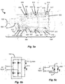
- FIG. 5a depicts an illustrative embodiment of an exemplary video endoscopic system 500, in accordance with the present application.
- the video endoscopic system 500 includes a camera head 506, and a combined video endoscope/endocoupler device 504 coupled to the camera head 506.
- the video endoscope/endocoupler device 504 includes an elongated insertion tube 508, and an illumination post housing 512 for housing the solid-state light source 513 (e.g., an LED).
- the video endoscope/endocoupler device 504 further includes the focus assembly 514 adjacent a proximal region of the video endoscope/endocoupler device 504 for adjusting focusing optics contained in the video endoscope/endocoupler device 504 and/or the camera head 506.
- the camera head 506 is coupleable to the proximal region of the video endoscope/endocoupler device 504.
- the elongated insertion tube 508, which can be rigid or flexible, extends from a distal region of the video endoscope/endocoupler device 504 to a distal end section of the video endoscopic system 500.
- the elongated insertion tube 508 includes the optical fiber bundle 521 for use in providing an optical path for directing light energy produced by the solid-state light source 513 to the distal end section of the video endoscopic system 500.
- the video endoscopic system 500 further includes a multi-stage electromagnetic induction coupling mechanism that can wirelessly transfer power from the camera head 506 to the video endoscope/endocoupler device 504, and ultimately to the solid-state light source 513 housed in the illumination post housing 512, while allowing rotational motion, about an axis 522, of at least the camera head 506 and the video endoscope/endocoupler device 504 (including the focus assembly 514) relative to one another.
- a multi-stage electromagnetic induction coupling mechanism can wirelessly transfer power from the camera head 506 to the video endoscope/endocoupler device 504, and ultimately to the solid-state light source 513 housed in the illumination post housing 512, while allowing rotational motion, about an axis 522, of at least the camera head 506 and the video endoscope/endocoupler device 504 (including the focus assembly 514) relative to one another.
- the multi-stage electromagnetic induction coupling mechanism can include at least three stages, namely, a first rotary induction coupling stage 515, a second rotary induction coupling stage 525, and a third rotary induction coupling stage 535.
- the first, second, and third rotary induction coupling stages 515, 525, 535 can each be implemented as a rotary transformer or any other suitable rotary power transfer device.
- the first rotary induction coupling stage 515 is disposed between the camera head 506 and the video endoscope/endocoupler device 504 at or near the proximal region of the video endoscope/endocoupler device 504.
- the focus assembly 514 is disposed between the first rotary induction coupling stage 515 and the second rotary induction coupling stage 525.
- the second rotary induction coupling stage 525 is disposed between the focus assembly 514 and the third rotary induction coupling stage 535.
- the third rotary induction coupling stage 535 is disposed at or near the distal region of the video endoscope/endocoupler device 504.
- the first rotary induction coupling stage 515 can include a first coil/ferrite assembly 517 and a second coil/ferrite assembly 519.
- the first and second coil/ferrite assemblies 517, 519 can be disposed longitudinally (or radially) about the axis 522 of the video endoscopic system 500.
- the first rotary induction coupling stage 515 can include a threaded mount 550, such as a C-mount or any other suitable rotary attachment mechanism, for use in rotatably attaching the video endoscope/endocoupler device 504 to the camera head 506.
- the second rotary induction coupling stage 525 can include a first coil/ferrite assembly 527 and a second coil/ferrite assembly 529.
- the first and second coil/ferrite assemblies 527, 529 can be disposed longitudinally (or radially) about the axis 522 of the video endoscopic system 500.
- the first and second rotary induction coupling stages 515, 525 are configured to allow rotational motion of the focus assembly 514 disposed therebetween about the axis 522 of the video endoscopic system 500.
- the third rotary induction coupling stage 535 can include a first coil/ferrite assembly 537 and a second coil/ferrite assembly 539.
- the first and second coil/ferrite assemblies 537, 539 can be disposed longitudinally (or radially) about the axis 522 of the video endoscopic system 500.
- the third rotary induction coupling stage 535 can include a rotary joint 550 or any other suitable mechanism configured to allow such axial rotational motion.
- the video endoscopic system 500 includes the rectifier circuit 523 that can convert an AC current provided by the third rotary induction coupling stage 535 to a DC current for powering the solid-state light source 513 (e.g., an LED) housed in the illumination post housing 512.
- FIG. 5b depicts an illustrative embodiment of the rectifier circuit 523, which includes a plurality of diodes D1, D2, D3, D4 configured as a bridge rectifier operative to receive the AC current as input, and to convert the AC input to a DC current for powering the LED 513.
- FIG. 5c depicts an alternative embodiment of the circuit of FIG.
- the LED 513 is replaced by a plurality of solid-state light sources 560, 562 (e.g., at least two LEDs) connected in anti-parallel fashion.
- the plurality of LEDs 560, 562 are powered directly by the AC input, obviating the need for the rectifier circuit 523.
- the cathode of the LED 560 and the anode of the LED 562 are connected to a node A, and the cathode of the LED 562 and the anode of the LED 560 are connected to a node B.
- the LEDs 560, 562 are energized on alternating halves of the AC waveform.
- the plurality of LEDs 560, 562 can be implemented as a plurality of blue/UV LED chips, which can constitute the core of one or more white LEDs.
- one or more additional LEDs can be connected in parallel with the LED 560, and, likewise, one or more additional LEDs can be connected in parallel with the LED 562, while maintaining the anti-parallel circuit configuration of the plurality of LEDs.
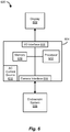
- FIG. 6 depicts an illustrative embodiment of an exemplary computerized medical system 600 that incorporates an endoscopic system 606, which can be like any one of the endoscopic systems 100, 300, 400, 500 described herein.
- the computerized medical system 600 includes the endoscopic system 606, a computing device 604, and a display device 602.
- the endoscopic system 606 can send image data of a patient's internal anatomical structures to the computing device 604, which can receive the image data via, e.g., a suitable video/frame capture device.
- the computing device 604 can perform processing on the image data to segment target tissue and/or anatomical structures in the image data from other tissue and/or structures, and to display corresponding images on the display device 602 in a manner that conveys such segmentation to a user, such as a surgeon or other medical professional.
- the computing device 604 includes a camera interface 614 that can receive the image data from the endoscopic system 606, provide power (in conjunction with the AC current source 616) to the endoscopic system 606, and further provide bidirectional communications with the endoscopic system 606.
- the computing device 604 may be embodied as any suitable type of computing device, such as a personal computer, a workstation, a portable computing device, a console, a laptop, a tablet, a network terminal, an embedded device, or the like.
- the computing device 604 further includes an interconnection mechanism such as a data bus or other circuitry that couples the camera interface 614 to a memory 610, a processor 612, and an input/output (I/O) interface 608.
- the memory 610 may be embodied as any suitable type of computer readable medium, which may include, e.g., a floppy disk, a hard disk, a Read Only Memory (ROM), and/or a Random Access Memory (RAM).
- the memory 610 can store one or more software programs/applications for execution by the processor 612.
- the stored software program/applications may include instructions that, when executed by the processor 612, causes the processor 612 to perform various operations described herein.
- the processor 612 can access the memory 610 via the interconnection mechanism in order to execute the software program/application(s).
- the processor 612 and the memory 610 may be replaced with programmable circuitry such as a field programmable gate array (FPGA), which may be programmed to execute the logic of the software program/application.
- FPGA field programmable gate array
- the endoscopic system 100 (see FIG. 1 ) is provided, including the camera head 106, the endoscopic device 102, the endocoupler 104 coupling the camera head 106 to the endoscopic device 102, the first rotary induction coupling stage 202 (see FIG. 2 ) disposed between the camera head 106 and the endocoupler 104, and the second rotary induction coupling stage 204 (see also FIG. 2 ) disposed between the endocoupler 104 and the endoscopic device 102.
- a first AC current is provided, by the camera head 106, to the first coil/ferrite assembly within the first rotary induction coupling stage 202, causing a first magnetic field to be generated by the first coil/ferrite assembly of the first rotary induction coupling stage 202.
- the first magnetic field is captured by the second coil/ferrite assembly within the first rotary induction coupling stage 202, causing a second AC current to be induced in the second coil/ferrite assembly of the first rotary induction coupling stage 202.
- the second AC current is provided to the first coil/ferrite assembly within the second rotary induction coupling stage 204, causing a second magnetic field to be generated by the first coil/ferrite assembly of the second rotary induction coupling stage 204.
- the second magnetic field is captured by the second coil/ferrite assembly within the second rotary induction coupling stage 204, causing a third AC current to be induced in the second coil/ferrite assembly of the second rotary induction coupling stage 204.
- the third AC current is converted to a DC current, which is provided for powering the solid-state light source housed in the illumination post housing 112 of the endoscopic device 102.
- the endoscopic device 102 is rotated, by a user (e.g., a surgeon or other medical professional), about its axis at the second rotary induction coupling stage 204 in order to change the orientation of the distal end section 120 of the endoscopic device 102, while maintaining the transfer of power by the second rotary induction coupling stage 204 from the endocoupler 104 to the solid-state light source housed in the endoscopic device 102.
- a user e.g., a surgeon or other medical professional
- a focusing ring assembly 114 implemented in the endocoupler 104 is rotated, by the user, about its axis at the first rotary induction coupling stage 202 in order to adjust focusing optics contained in the endocoupler 104 and/or the camera head 106, while further maintaining the transfer of power by the first rotary induction coupling stage 202 from the camera head 106 to the endocoupler 104, and ultimately to the solid-state light source housed in the endoscopic device 102.
Landscapes
- Health & Medical Sciences (AREA)
- Life Sciences & Earth Sciences (AREA)
- Surgery (AREA)
- Engineering & Computer Science (AREA)
- Physics & Mathematics (AREA)
- Optics & Photonics (AREA)
- Biomedical Technology (AREA)
- Molecular Biology (AREA)
- Pathology (AREA)
- Nuclear Medicine, Radiotherapy & Molecular Imaging (AREA)
- Biophysics (AREA)
- Heart & Thoracic Surgery (AREA)
- Medical Informatics (AREA)
- Radiology & Medical Imaging (AREA)
- Animal Behavior & Ethology (AREA)
- General Health & Medical Sciences (AREA)
- Public Health (AREA)
- Veterinary Medicine (AREA)
- Computer Networks & Wireless Communication (AREA)
- Microelectronics & Electronic Packaging (AREA)
- Endoscopes (AREA)
- Instruments For Viewing The Inside Of Hollow Bodies (AREA)
Description
- This application claims benefit of the priority of
U.S. Provisional Patent Application No. 62/081,158 filed November 18, 2014 - The present application relates generally to endoscopic systems and methods, and more specifically to systems and methods of providing wireless power transmission from a camera head to one or more solid-state light sources housed in an endoscopic device.
- Surgeons and other medical professionals frequently employ endoscopic systems and methods to inspect regions within a patient's body during surgical, diagnostic, and/or other medical procedures. For example, a surgeon may employ an endoscopic system to inspect a patient's abdominal or pelvic cavity during a laparoscopic procedure, or to inspect a patient's thoracic or chest cavity during a thoracoscopic procedure. Such an endoscopic system may be employed in conjunction with surgical instruments such as forceps, scissors, probes, etc., to perform such a laparoscopic or thoracoscopic procedure through a small incision made in the patient's body, avoiding the need to open the patient's abdomen or chest. In this way, the patient's pain and/or discomfort due to the medical procedure, as well as the patient's recovery time, can be reduced.
- A conventional endoscopic system typically includes a camera head, an endocoupler, an endoscopic device, a light source, and a light cable. The endocoupler mechanically and optically couples the camera head to the endoscopic device, and the light cable connects the light source to the endoscopic device. The endoscopic device typically includes an elongated insertion tube that extends from the endocoupler to a distal end of the endoscopic device, as well as an optical fiber bundle that provides an optical path for directing light energy produced by the light source to the distal end of the endoscopic device.
US 2006/116550 A1 describes an endoscope system in which an endoscope can be cleaned and sterilized more easily. The endoscope system comprising an endoscope having an inserting portion inserted in the body cavity, which is re-used by cleaning and sterilizing the inserting portion after ending the examination and treatment. -
US 2006/171693 A1 describes an endoscope with integrated light source. An LED based light source unit for an endoscopic imaging system produces illumination for a camera through an endoscope. The light source unit includes an array of LEDs mounted to a thermally conductive substrate. -
US 2011/018988 A1 describes endoscopic imaging system includes an endoscope. The described endoscopic imaging system includes an endoscope, a light source to transmit light through illumination channels in the endoscope, and an imaging unit to receive images of a region of interest that are formed at a tip of the endoscope that is inserted into the region. The components of the system are freely attachable and detachable from each other. -
US 2011/193948 A1 describes an endoscope video system. The system including an endoscope and a detachable camera head. The endoscope is provided with a transponder/transceiver and the detachable camera head is provided with a corresponding transponder/transceiver such that electrical power is transmitted from the camera head to the endoscope. - The conventional endoscopic system described above has drawbacks, however, due atleast to the low efficiency and high power of the light source. Such a light source is typically a lamp that can require as much as 300 Watts of power or more in order to deliver about 1 Watt of light to the distal end of the endoscopic device, resulting in an efficiency of about 0.3%. Moreover, the light source in combination with the light cable can be bulky and can add needless clutter to the surgical suite, as we]) as significantly increase the overall cost of the endoscopic system.
- It would therefore be desirable to have systems and methods of implementing a light source in an endoscopic system that can avoid at least some of the drawbacks of conventional endoscopic systems.
- In accordance with the present appli ation, endoscopic systems and methods are disclosed that provide wireless power transmission from a camera head to at least one solid-state light source housed in an endoscopic device. The disclosed endoscopic systems and methods employ a multi-stage electromagnetic induction coupling mechanism that can wirelessly transfer power from the camera head to an endocoupler, as well as from the endocoupler to the solid-state light source, while allowing axial rotational motion of at least the camera head, the endocoupler, and/or the endoscopic device relative to one another.
- In one aspect, an exemplary endoscopic system includes a camera head, an endoscopic device, and an endocoupler that couples the camera head to the endoscopic device. The camera head is coupled to a proximal region of the endocoupler, and the endoscopic device is coupled to a distal region of the endocoupler. In an exemplary aspect, the endoscopic device can be a direct-view endoscope. The endoscopic device includes an elongated insertion tube, an illumination post housing, and an optical fiber bundle. The elongated insertion tube, which can be rigid or flexible, extends from about the distal region of the endocoupler to a distal end section of the endoscopic device. The illumination post housing can house at least one solid-state light source. In a further exemplary aspect, the solid-state light source can be a light-emitting diode (LED). The optical fiber bundle of the elongated insertion tube provides an optical path for directing light energy produced by the solid-state light source to the distal end section of the endoscopic device.
- In this aspect, the endoscopic system further includes a multi-stage electromagnetic induction coupling mechanism that can wirelessly transfer power from the camera head to the endocoupler, as well as from the endocoupler to the solid-state light source housed in the illumination post housing, while allowing axial rotational motion of at least the camera head, the endocoupler, and/or the endoscopic device relative to one another. In an exemplary aspect, the multi-stage electromagnetic induction coupling mechanism includes at least a first rotary induction coupling stage and a second rotary induction coupling stage. The first rotary induction coupling stage is disposed between the camera head and the endocoupler at or near the proximal region of the endocoupler. The second rotary induction coupling stage is disposed between the endocoupler and the endoscopic device at or near the distal region of the endocoupler. In a further exemplary aspect, the first and second rotary induction coupling stages can each include a first coil/ferrite assembly that has a magnetic field generating coil wound around a first ferrite core, and a second coil/ferrite assembly that has a magnetic field capturing coil wound around a second ferrite core. In order to allow axial rotational motion of the camera head and the endocoupler relative to one another, the first and second coil/ferrite assemblies included in the first rotary induction coupling stage can be implemented as a rotary power transfer device, such as a rotary transformer. The first rotary induction coupling stage can further include a first rotary attachment mechanism, such as a threaded mount, for rotatably attaching the endocoupler to the camera head. In order to allow axial rotational motion of the endoscopic device and the endocoupler relative to one another, the first and second coil/ferrite assemblies included in the second rotary induction coupling stage can likewise be implemented as a rotary power transfer device, such as a rotary transformer. The second rotary induction coupling stage can further include a second rotary attachment mechanism, such as a rotary joint, for rotatably attaching the endocoupler to the endoscopic device.
- In an exemplary mode of operation, an endoscopic system is provided that includes a camera head, an endoscopic device, an endocoupler coupling the camera head to the endoscopic device, a first rotary induction coupling stage disposed between the camera head and the endocoupler, and a second rotary induction coupling stage disposed between the endocoupler and the endoscopic device, which houses at least one solid-state light source. Power is provided, by the camera head, for powering the solid-state light source by providing a first alternating current (also referred to herein as the "first AC current") to a first coil/ferrite assembly within the first rotary induction coupling stage, thereby causing a first magnetic field to be generated by the first coil/ferrite assembly of the first rotary induction coupling stage. The first magnetic field generated by the first coil/ferrite assembly of the first rotary induction coupling stage is captured by a second coil/ferrite assembly within the first rotary induction coupling stage, thereby causing a second alternating current (also referred to herein as the "second AC current") to be induced in the second coil/ferrite assembly of the first rotary induction coupling stage. The second AC current is provided to a first coil/ferrite assembly within the second rotary induction coupling stage, thereby causing a second magnetic field to be generated by the first coil/ferrite assembly of the second rotary induction coupling stage. The second magnetic field generated by the first coil/ferrite assembly of the second rotary induction coupling stage is captured by a second coil/ferrite assembly within the second rotary induction coupling stage, thereby causing a third alternating current (also referred to herein as the "third AC current") to be induced in the second coil/ferrite assembly of the second rotary induction coupling stage. The third AC current is converted to a direct current (also referred to herein as the "DC current"), which is provided for powering the solid-state light source housed in the illumination post housing of the endoscopic device. Having powered the solid-state light source, the endoscopic device is rotated, by a user, about its axis at the second rotary induction coupling stage in order to change the orientation of a distal end section of the endoscopic device, while maintaining the transfer of power by the second rotary induction coupling stage from the endocoupler to the solid-state light source housed in the endoscopic device. Once having changed the orientation of the distal end section of the endoscopic device, a focusing ring assembly implemented in the endocoupler is rotated, by the user, about its axis at the first rotary induction coupling stage in order to adjust focusing optics contained in the endocoupler and/or the camera head, while further maintaining the transfer of power by the first rotary induction coupling stage from the camera head to the endocoupler, and ultimately to the solid-state light source.
- By providing an endoscopic system that includes a camera head, an endoscopic device, an endocoupler coupling the camera head to the endoscopic device, a first rotary induction coupling stage disposed between the camera head and the endocoupler, and at least a second rotary induction coupling stage disposed between the endocoupler and the endoscopic device, a user (e.g., a surgeon or other medical professional) can axially rotate the endoscopic device at the second rotary induction coupling stage relative to the endocoupler, and also axially rotate a focusing ring assembly implemented in the endocoupler at the first rotary induction coupling stage relative to the camera head, while advantageously maintaining a transfer of power from the camera head to the endocoupler across the first rotary induction coupling stage, as well as from the endocoupler to the endoscopic device across the second rotary induction coupling stage, for powering a solid-state light source housed in the endoscopic device. Such a solid-state light source (e.g., an LED) can require about 5 Watts of power in order to deliver about 1 Watt of light to a distal end of the endoscopic device, advantageously resulting in an increased efficiency of about 20%.
- Other features, functions, and aspects of the invention will be evident from the Detailed Description that follows.
- The accompanying drawings, which are incorporated in and constitute a part of this specification, illustrate one or more embodiments described herein and, together with the Detailed Description, explain these embodiments. In the drawings:
-
FIG. 1 is a diagram of an exemplary endoscopic system, including a camera head, an endoscopic device, and an endocoupler coupling the camera head to the endoscopic device, in accordance with the present application; -
FIG. 2 is a detailed partially cross-sectional view of the camera head, the endocoupler, and the endoscopic device included in the endoscopic system ofFIG. 1 ; -
FIG. 3 is a detailed partially cross-sectional view of an endocoupler and an endoscopic device included in a first alternative embodiment of the endoscopic system ofFIG. 1 ; -
FIG. 4 is a detailed partially cross-sectional view of an endocoupler and an endoscopic device included in a second alternative embodiment of the endoscopic system ofFIG. 1 ; -
FIG. 5a is a detailed cross-sectional view of a camera head and a video endoscopic device included in a video endoscopic system, in accordance with the present application; -
FIG. 5b is a schematic diagram of an exemplary rectifier circuit and an exemplary solid-state light source included in the video endoscopic system ofFIG. 5a , the rectifier circuit being configured to convert an alternating current (AC) input to a direct current (DC) for powering the solid-state light source; -
FIG. 5c is a schematic diagram of an alternative embodiment of the circuit ofFIG. 5b , in which two solid-state light sources connected in anti-parallel fashion are powered by the AC input; -
FIG. 6 is a block diagram of a computerized medical system incorporating the endoscopic system ofFIG. 1 ; and -
FIG. 7 is a flow diagram of an exemplary method of operating the endoscopic system ofFIG.1 . - The disclosure of
U.S. Provisional Patent Application No. 62/081,158 filed November 18, 2014 - Endoscopic systems and methods are disclosed that provide wireless power transmission from a camera head to at least one solid-state light source housed in an endoscopic device. The disclosed endoscopic systems and methods employ a multi-stage electromagnetic induction coupling mechanism that can wirelessly transfer power from the camera head to an endocoupler, as well as from the endocoupler to the solid-state light source, while allowing axial rotational motion of at least the camera head, the endocoupler, and/or the endoscopic device relative to one another.
-
FIG. 1 depicts an illustrative embodiment of an exemplaryendoscopic system 100, in accordance with the present application. As shown inFIG. 1 , theendoscopic system 100 includes acamera head 106, anendoscopic device 102, and anendocoupler 104 configured to couple thecamera head 106 to theendoscopic device 102. For example, a surgeon or other medical professional may employ theendoscopic system 100 to inspect a region within a patient's body during a laparoscopic procedure, a thoracoscopic procedure, or any other suitable surgical, diagnostic, or other medical procedure. Theendoscopic device 102 includes anelongated insertion tube 108, aneyepiece section 110, and anillumination post housing 112 for housing at least one solid-state light source (e.g., a solid-state light source 513; seeFIG. 5a ). Theendocoupler 104 includes a focusingring 114 of a focus assembly (e.g., afocus assembly 514; seeFIG. 5a ) for adjusting focusing optics (e.g., at least onelens 218; seeFIG. 2 ) contained in theendocoupler 104 and/or thecamera head 106. Through the focusing optics, theendocoupler 104 can project an image viewed through theeyepiece section 110 of theendoscopic device 102 onto an imaging sensor of thecamera head 106. Thecamera head 106 is coupled to aproximal region 118 of theendocoupler 104, and theendoscopic device 102 is coupled to adistal region 116 of theendocoupler 104. In one embodiment, theendoscopic device 102 can be a direct-view endoscope, or any other suitable endoscope. Theelongated insertion tube 108, which can be rigid or flexible, extends from theeyepiece section 110 to adistal end section 120 of theendoscopic device 102. In one embodiment, the solid-state light source 513 (seeFIG. 5a ) can be a light-emitting diode (LED). Theelongated insertion tube 108 can include an optical fiber bundle (e.g., anoptical fiber bundle 521; seeFIG. 5a ) in order to provide an optical path for directing light energy produced by the solid-state light source to thedistal end section 120 of theendoscopic device 102. - The disclosed
endoscopic system 100 further includes a multi-stage electromagnetic induction coupling mechanism that can wirelessly transfer power from thecamera head 106 to theendocoupler 104, as well as from theendocoupler 104 to the solid-state light source housed in theillumination post housing 112, while allowing rotational motion, about anaxis 122, of at least thecamera head 106, theendocoupler 104, and/or theendoscopic device 102 relative to one another. As shown inFIG. 2 , the multi-stage electromagnetic induction coupling mechanism can include at least a first rotaryinduction coupling stage 202 and a second rotaryinduction coupling stage 204. The first rotaryinduction coupling stage 202 is disposed between thecamera head 106 and theendocoupler 104 at or near theproximal region 118 of theendocoupler 104. The second rotaryinduction coupling stage 204 is disposed between theendocoupler 104 and theendoscopic device 102 at or near thedistal region 116 of theendocoupler 104. - As further shown in
FIG. 2 , the first rotaryinduction coupling stage 202 can include a first coil/ferrite assembly (not numbered) that has a magneticfield generating coil 206 wound around aferrite core 207, and a second coil/ferrite assembly (not numbered) that has a magneticfield capturing coil 208 wound around aferrite core 209. The first coil/ferrite assembly and the second coil/ferrite assembly of the first rotaryinduction coupling stage 202 are disposed longitudinally about theaxis 122 of theendoscopic system 100. In order to allow axial rotational motion of thecamera head 106 and theendocoupler 104 relative to one another, the first and second coil/ferrite assemblies of the first rotaryinduction coupling stage 202 can be implemented as a rotary transformer or any other suitable rotary power transfer device. In the case where the first and second coil/ferrite assemblies of the first rotaryinduction coupling stage 202 are implemented as a rotary transformer, one of the coil/ferrite assemblies can have a fixed coil, while the other coil/ferrite assembly has a rotatable coil. The first rotaryinduction coupling stage 202 can further include a threadedmount 220, such as a C-mount or any other suitable rotary attachment mechanism, for use in rotatably attaching theendocoupler 104 to thecamera head 106. - With regard to
FIG. 2 , the second rotaryinduction coupling stage 204 of theendoscopic system 100 can include a first coil/ferrite assembly (not numbered) that has a magneticfield generating coil 210 wound around aferrite core 215, and a second coil/ferrite assembly (not numbered) that has a magneticfield capturing coil 212 wound around aferrite core 213. The first coil/ferrite assembly and the second coil/ferrite assembly of the second rotaryinduction coupling stage 204 are disposed longitudinally about theaxis 122 of theendoscopic system 100. In order to allow axial rotational motion of theendoscopic device 102 and theendocoupler 104 relative to one another, the first and second coil/ferrite assemblies of the second rotaryinduction coupling stage 204 can be implemented as a rotary transformer or any other suitable rotary power transfer device. In the case where the first and second coil/ferrite assemblies of the second rotaryinduction coupling stage 204 are implemented as a rotary transformer, one of the coil/ferrite assemblies can have a fixed coil, while the other coil/ferrite assembly has a rotatable coil. The second rotaryinduction coupling stage 204 can further include a rotary joint 211 or any other suitable rotary attachment mechanism, for use in rotatably attaching theendocoupler 104 to theendoscopic device 102. - In one mode of operation, an alternating current (AC) source (also referred to herein as the "AC current source") (e.g., an AC
current source 616; seeFIG. 6 ) provides, via a first conductor disposed in achannel 222, a first AC current to the first coil/ferrite assembly of the first rotaryinduction coupling stage 202, causing a first magnetic field to be generated by the magneticfield generating coil 206. The magneticfield capturing coil 208 included in the second coil/ferrite assembly of the first rotaryinduction coupling stage 202 captures the first magnetic field generated by the magneticfield generating coil 206, causing a second AC current to be induced in the magneticfield capturing coil 208. A second conductor disposed in achannel 216 provides the second AC current to the first coil/ferrite assembly of the second rotaryinduction coupling stage 204, causing a second magnetic field to be generated by the magneticfield generating coil 210. The magneticfield capturing coil 212 included in the second coil/ferrite assembly of the second rotaryinduction coupling stage 204 captures the second magnetic field generated by the magneticfield generating coil 210, causing a third AC current to be induced in the magneticfield capturing coil 212. A third conductor disposed in achannel 214 provides the third AC current to a rectifier circuit (e.g., arectifier circuit 523; seeFIG. 5a ), such as a bridge rectifier or any other suitable rectifier circuit, which converts the third AC current to a direct current (also referred to herein as the "DC current") for powering the solid-state light source (e.g., an LED) housed in theillumination post housing 112 of theendoscopic device 102. Having powered the solid-state light source of theendoscopic device 102, theendoscopic device 102 can be rotated, by a user (e.g., a surgeon or other medical professional), about theaxis 122 at the second rotaryinduction coupling stage 204 in order to change the orientation of thedistal end section 120 of theendoscopic device 102, while maintaining the transfer of power by the first and second coil/ferrite assemblies (e.g., a rotary transformer) of the second rotaryinduction coupling stage 204 from theendocoupler 104 to the solid-state light source. Once having changed the orientation of thedistal end section 120 of theendoscopic device 102, the focusingring 114 of the focus assembly can be rotated, by the user, about theaxis 122 at the first rotaryinduction coupling stage 202 in order to adjust the focusing optics contained in theendocoupler 104 and/or thecamera head 106, while further maintaining the transfer of power by the first and second coil/ferrite assemblies (e.g., another rotary transformer) of the first rotaryinduction coupling stage 202 from thecamera head 106 to theendocoupler 104. -
FIG. 3 depicts a first alternative embodiment of theendoscopic system 100 ofFIG. 1 . As shown inFIG. 3 , anendoscopic system 300 includes acamera head 306, anendoscopic device 302, and anendocoupler 304 configured to couple thecamera head 306 to theendoscopic device 302. Theendoscopic device 302 includes aneyepiece section 310. Theendocoupler 104 includes a focusingring 314 of a focus assembly for adjusting focusing optics contained in theendocoupler 304 and/or thecamera head 306. Theendoscopic system 300 further includes a multi-stage electromagnetic induction coupling mechanism that can wirelessly transfer power from thecamera head 306 to theendocoupler 304, as well as from theendocoupler 304 to a solid-state light source (e.g., an LED) housed in theendoscopic device 302, while allowing rotational motion, about anaxis 322, of at least thecamera head 306, theendocoupler 304, and/or theendoscopic device 302 relative to one another. As further shown inFIG. 3 , the multi-stage electromagnetic induction coupling mechanism can include at least a rotaryinduction coupling stage 303 disposed between theendocoupler 304 and theendoscopic device 302 at or near a distal region of theendocoupler 304. The rotaryinduction coupling stage 303 can include a first coil/ferrite assembly 307 and a second coil/ferrite assembly 309. Another such rotary induction coupling stage, which can be disposed between thecamera head 306 and theendocoupler 304 at or near a proximal region of theendocoupler 304, is not shown for clarity of illustration. Whereas the first and second coil/ferrite assemblies of the rotary induction coupling stage 204 (seeFIG. 2 ) (as well as the first and second coil/ferrite assemblies of the rotaryinduction coupling stage 202; see alsoFIG. 2 ) are disposed longitudinally about theaxis 122 of theendoscopic system 100, the first and second coil/ferrite assemblies FIG. 3 ) are disposed radially about theaxis 322 of theendoscopic system 300. In one embodiment, the radially disposed first and second coil/ferrite assemblies -
FIG. 4 depicts a second alternative embodiment of theendoscopic system 100 ofFIG. 1 . As shown inFIG. 4 , anendoscopic system 400 includes acamera head 406, anendoscopic device 402, and anendocoupler 404 configured to couple thecamera head 406 to theendoscopic device 402. Theendoscopic device 402 includes aneyepiece section 410. Theendocoupler 404 includes a focusingring 414 of a focus assembly for adjusting focusing optics contained in theendocoupler 404 and/or thecamera head 406. Theendoscopic system 400 further includes a multi-stage electromagnetic induction coupling mechanism that can wirelessly transfer power from thecamera head 406 to theendocoupler 404, as well as from theendocoupler 404 to a solid-state light source (e.g., an LED) housed in theendoscopic device 402, while allowing rotational motion, about anaxis 422, of at least thecamera head 406, theendocoupler 404, and/or theendoscopic device 402 relative to one another. As further shown inFIG. 4 , the multi-stage electromagnetic induction coupling mechanism can include at least a rotaryinduction coupling stage 403 disposed between theendocoupler 404 and theendoscopic device 402 at or near a distal region of theendocoupler 404. The rotaryinduction coupling stage 403 can include a first coil/ferrite assembly 407 and a second coil/ferrite assembly 409. Another such rotary induction coupling stage, which can be disposed between thecamera head 406 and theendocoupler 404 at or near a proximal region of theendocoupler 404, is not shown for clarity of illustration. Whereas the first and second coil/ferrite assemblies endoscopic system 300 can each include a single-turn coil (e.g., a single enameled wire, a plurality of litz wires), which typically has a round cross-section, the first and second coil/ferrite assemblies endoscopic system 400 can each include a coil that has a non-round cross-section, such as a flat cross-section. In one embodiment, the first and second coil/ferrite assemblies ferrite assemblies -
FIG. 5a depicts an illustrative embodiment of an exemplary videoendoscopic system 500, in accordance with the present application. As shown inFIG. 5a , thevideo endoscopic system 500 includes acamera head 506, and a combined video endoscope/endocoupler device 504 coupled to thecamera head 506. The video endoscope/endocoupler device 504 includes anelongated insertion tube 508, and anillumination post housing 512 for housing the solid-state light source 513 (e.g., an LED). The video endoscope/endocoupler device 504 further includes thefocus assembly 514 adjacent a proximal region of the video endoscope/endocoupler device 504 for adjusting focusing optics contained in the video endoscope/endocoupler device 504 and/or thecamera head 506. Thecamera head 506 is coupleable to the proximal region of the video endoscope/endocoupler device 504. Theelongated insertion tube 508, which can be rigid or flexible, extends from a distal region of the video endoscope/endocoupler device 504 to a distal end section of thevideo endoscopic system 500. Theelongated insertion tube 508 includes theoptical fiber bundle 521 for use in providing an optical path for directing light energy produced by the solid-state light source 513 to the distal end section of thevideo endoscopic system 500. - With regard to
FIG. 5a , thevideo endoscopic system 500 further includes a multi-stage electromagnetic induction coupling mechanism that can wirelessly transfer power from thecamera head 506 to the video endoscope/endocoupler device 504, and ultimately to the solid-state light source 513 housed in theillumination post housing 512, while allowing rotational motion, about anaxis 522, of at least thecamera head 506 and the video endoscope/endocoupler device 504 (including the focus assembly 514) relative to one another. As shown inFIG. 5a , the multi-stage electromagnetic induction coupling mechanism can include at least three stages, namely, a first rotaryinduction coupling stage 515, a second rotaryinduction coupling stage 525, and a third rotaryinduction coupling stage 535. For example, the first, second, and third rotary induction coupling stages 515, 525, 535 can each be implemented as a rotary transformer or any other suitable rotary power transfer device. The first rotaryinduction coupling stage 515 is disposed between thecamera head 506 and the video endoscope/endocoupler device 504 at or near the proximal region of the video endoscope/endocoupler device 504. Thefocus assembly 514 is disposed between the first rotaryinduction coupling stage 515 and the second rotaryinduction coupling stage 525. The second rotaryinduction coupling stage 525 is disposed between thefocus assembly 514 and the third rotaryinduction coupling stage 535. The third rotaryinduction coupling stage 535 is disposed at or near the distal region of the video endoscope/endocoupler device 504. - With further regard to
FIG. 5a , the first rotaryinduction coupling stage 515 can include a first coil/ferrite assembly 517 and a second coil/ferrite assembly 519. The first and second coil/ferrite assemblies axis 522 of thevideo endoscopic system 500. In order to allow axial rotational motion of thecamera head 506 and the video endoscope/endocoupler device 504 relative to one another, the first rotaryinduction coupling stage 515 can include a threadedmount 550, such as a C-mount or any other suitable rotary attachment mechanism, for use in rotatably attaching the video endoscope/endocoupler device 504 to thecamera head 506. The second rotaryinduction coupling stage 525 can include a first coil/ferrite assembly 527 and a second coil/ferrite assembly 529. The first and second coil/ferrite assemblies axis 522 of thevideo endoscopic system 500. The first and second rotary induction coupling stages 515, 525 are configured to allow rotational motion of thefocus assembly 514 disposed therebetween about theaxis 522 of thevideo endoscopic system 500. The third rotaryinduction coupling stage 535 can include a first coil/ferrite assembly 537 and a second coil/ferrite assembly 539. The first and second coil/ferrite assemblies axis 522 of thevideo endoscopic system 500. In order to allow axial rotational motion of the distal region of the video endoscope/endocoupler device 504 for changing the orientation of the distal end section of thevideo endoscopic system 500, the third rotaryinduction coupling stage 535 can include a rotary joint 550 or any other suitable mechanism configured to allow such axial rotational motion. - As shown in
FIG. 5a , thevideo endoscopic system 500 includes therectifier circuit 523 that can convert an AC current provided by the third rotaryinduction coupling stage 535 to a DC current for powering the solid-state light source 513 (e.g., an LED) housed in theillumination post housing 512.FIG. 5b depicts an illustrative embodiment of therectifier circuit 523, which includes a plurality of diodes D1, D2, D3, D4 configured as a bridge rectifier operative to receive the AC current as input, and to convert the AC input to a DC current for powering theLED 513.FIG. 5c depicts an alternative embodiment of the circuit ofFIG. 5b , in which theLED 513 is replaced by a plurality of solid-state light sources 560, 562 (e.g., at least two LEDs) connected in anti-parallel fashion. The plurality ofLEDs rectifier circuit 523. As shown inFIG. 5c , the cathode of theLED 560 and the anode of theLED 562 are connected to a node A, and the cathode of theLED 562 and the anode of theLED 560 are connected to a node B. When an AC voltage is applied across the nodes A and B, theLEDs LEDs LED 560, and, likewise, one or more additional LEDs can be connected in parallel with theLED 562, while maintaining the anti-parallel circuit configuration of the plurality of LEDs. -
FIG. 6 depicts an illustrative embodiment of an exemplary computerizedmedical system 600 that incorporates anendoscopic system 606, which can be like any one of theendoscopic systems FIG. 6 , the computerizedmedical system 600 includes theendoscopic system 606, acomputing device 604, and adisplay device 602. Theendoscopic system 606 can send image data of a patient's internal anatomical structures to thecomputing device 604, which can receive the image data via, e.g., a suitable video/frame capture device. Thecomputing device 604 can perform processing on the image data to segment target tissue and/or anatomical structures in the image data from other tissue and/or structures, and to display corresponding images on thedisplay device 602 in a manner that conveys such segmentation to a user, such as a surgeon or other medical professional. Thecomputing device 604 includes acamera interface 614 that can receive the image data from theendoscopic system 606, provide power (in conjunction with the AC current source 616) to theendoscopic system 606, and further provide bidirectional communications with theendoscopic system 606. - With regard to
FIG. 6 , thecomputing device 604 may be embodied as any suitable type of computing device, such as a personal computer, a workstation, a portable computing device, a console, a laptop, a tablet, a network terminal, an embedded device, or the like. Thecomputing device 604 further includes an interconnection mechanism such as a data bus or other circuitry that couples thecamera interface 614 to amemory 610, aprocessor 612, and an input/output (I/O)interface 608. Thememory 610 may be embodied as any suitable type of computer readable medium, which may include, e.g., a floppy disk, a hard disk, a Read Only Memory (ROM), and/or a Random Access Memory (RAM). Thememory 610 can store one or more software programs/applications for execution by theprocessor 612. The stored software program/applications may include instructions that, when executed by theprocessor 612, causes theprocessor 612 to perform various operations described herein. During operation of thecomputing device 604, theprocessor 612 can access thememory 610 via the interconnection mechanism in order to execute the software program/application(s). In other implementations, theprocessor 612 and thememory 610 may be replaced with programmable circuitry such as a field programmable gate array (FPGA), which may be programmed to execute the logic of the software program/application. - An exemplary method of operating the
endoscopic system 100 is described below with reference toFIGS. 1 ,2 , and7 . As depicted in block 702 (seeFIG. 7 ), the endoscopic system 100 (seeFIG. 1 ) is provided, including thecamera head 106, theendoscopic device 102, theendocoupler 104 coupling thecamera head 106 to theendoscopic device 102, the first rotary induction coupling stage 202 (seeFIG. 2 ) disposed between thecamera head 106 and theendocoupler 104, and the second rotary induction coupling stage 204 (see alsoFIG. 2 ) disposed between theendocoupler 104 and theendoscopic device 102. As depicted in block 704, a first AC current is provided, by thecamera head 106, to the first coil/ferrite assembly within the first rotaryinduction coupling stage 202, causing a first magnetic field to be generated by the first coil/ferrite assembly of the first rotaryinduction coupling stage 202. As depicted in block 706, the first magnetic field is captured by the second coil/ferrite assembly within the first rotaryinduction coupling stage 202, causing a second AC current to be induced in the second coil/ferrite assembly of the first rotaryinduction coupling stage 202. As depicted in block 708, the second AC current is provided to the first coil/ferrite assembly within the second rotaryinduction coupling stage 204, causing a second magnetic field to be generated by the first coil/ferrite assembly of the second rotaryinduction coupling stage 204. As depicted in block 710, the second magnetic field is captured by the second coil/ferrite assembly within the second rotaryinduction coupling stage 204, causing a third AC current to be induced in the second coil/ferrite assembly of the second rotaryinduction coupling stage 204. As depicted in block 712, the third AC current is converted to a DC current, which is provided for powering the solid-state light source housed in theillumination post housing 112 of theendoscopic device 102. As depicted inblock 714, having powered the solid-state light source, theendoscopic device 102 is rotated, by a user (e.g., a surgeon or other medical professional), about its axis at the second rotaryinduction coupling stage 204 in order to change the orientation of thedistal end section 120 of theendoscopic device 102, while maintaining the transfer of power by the second rotaryinduction coupling stage 204 from theendocoupler 104 to the solid-state light source housed in theendoscopic device 102. As depicted inblock 716, once having changed the orientation of thedistal end section 120 of theendoscopic device 102, a focusingring assembly 114 implemented in theendocoupler 104 is rotated, by the user, about its axis at the first rotaryinduction coupling stage 202 in order to adjust focusing optics contained in theendocoupler 104 and/or thecamera head 106, while further maintaining the transfer of power by the first rotaryinduction coupling stage 202 from thecamera head 106 to theendocoupler 104, and ultimately to the solid-state light source housed in theendoscopic device 102. - It will be appreciated by those of ordinary skill in the art that modifications to and variations of the above-described systems and methods may be made without departing from the inventive concepts disclosed herein. Accordingly, the invention should not be viewed as limited except as by the scope and spirit of the appended claims.
Claims (18)
- An endoscopic system (100),
comprising: a camera head (106);
an endoscopic device (102) including one or more solid-state light sources;
an endocoupler (104) operative to couple the camera head (106) to the endoscopic device; and
a multi-stage electromagnetic induction coupling mechanism operative to transfer power from the camera head (106) to the endocoupler (104), and to further transfer the power from the endocoupler (104) to the endoscopic device (102) for powering the one or more solid-state light sources, while allowing axial rotational motion of one or more of the camera head (106), the endocoupler (104), and the endoscopic device (102) relative to one another. - The endoscopic system (100) of claim 1 wherein the one or more solid-state light sources include one or more light-emitting diodes (LEDs).
- The endoscopic system (100) of claim 2 further
comprising: a rectifier circuit (523),
wherein the multi-stage electromagnetic induction coupling mechanism is further operative to provide an alternating current (AC) input to the rectifier circuit (523), and
wherein the rectifier circuit (523) is operative to convert the AC input to a direct current for powering the one or more LEDs. - The endoscopic system (100) of claim 2 wherein the one or more LEDs include a plurality of LEDs connected in anti-parallel fashion, and wherein the multi-stage electromagnetic induction coupling mechanism is further operative to provide an alternating current (AC) input to the plurality of LEDs connected in anti-parallel fashion for powering the plurality of LEDs.
- The endoscopic system (100) of claim 1 wherein the multi-stage electromagnetic induction coupling mechanism includes at least a first rotary induction coupling stage (202) and a second rotary induction coupling stage (204), the first rotary induction coupling stage (202) being disposed between the camera head (106) and the endocoupler (104), and the second rotary induction coupling stage (204) being disposed between the endocoupler (104) and the endoscopic device (102); optionally wherein the first rotary induction coupling stage (202) includes a first rotary power transfer device and a first rotary attachment mechanism, the first rotary power transfer device being operative to wirelessly transfer the power from the camera head (106)_to the endocoupler (104), and the first rotary attachment mechanism being operative to rotatably attach the endocoupler to the camera head.
- The endoscopic system (100) of claim 5 wherein the first rotary attachment mechanism includes a threaded mount (505).
- The endoscopic system (100) of claim 5 wherein the second rotary induction coupling stage includes a second rotary power transfer device and a second rotary attachment mechanism, the second rotary power transfer device being operative to wirelessly transfer the power from the endocoupler (104) to the endoscopic device (102), and the second rotary attachment mechanism being operative to rotatably attach the endocoupler (104) to the endoscopic device (102).
- The endoscopic system (100) of claim 7 wherein the second rotary attachment mechanism includes a rotary joint; or wherein one or more of the first rotary power transfer device and the second rotary power transfer device include a rotary transformer; or wherein one or more of the first rotary induction coupling stage and the second rotary induction coupling stage include a first coil/ferrite assembly that has a magnetic field generating coil wound around a first ferrite core, and a second coil/ferrite assembly that has a magnetic field capturing coil wound around a second ferrite core.
- The endoscopic system (100) of claim 8 wherein the first coil/ferrite assembly and the second coil/ferrite assembly are disposed longitudinally about an axis of the endoscopic system (122).
- The endoscopic system (100) of claim 9 wherein one or more of the first coil/ferrite assembly and the second coil/ferrite assembly include a flat or ribbon wire.
- The endoscopic system (100) of claim 8 wherein the first coil/ferrite assembly and the second coil/ferrite assembly are disposed radially about an axis of the endoscopic system (122).
- The endoscopic system (100) of claim 11 wherein one or more of the first coil/ferrite assembly and the second coil/ferrite assembly include a single enameled wire or a plurality of litz wires.
- The endoscopic system (100) of claim 5 wherein the endocoupler includes a focusing ring assembly operative to rotate at least at the first rotary induction coupling stage about an axis of the endoscopic system (122), thereby adjusting focusing optics contained in one or more of the endocoupler (104) and the camera head (106).
- The endoscopic system (100) of claim 13 wherein the multi-stage electromagnetic induction coupling mechanism further includes a third rotary induction coupling stage (535) disposed between the focusing ring (414) assembly and the second rotary induction coupling stage (525), the focusing ring assembly being further operative to rotate at the third rotary induction coupling stage (535) about the axis of the endoscopic system (122).
- A method of operating an endoscopic system, comprising:providing an endoscopic system including a camera head, an endoscopic device, an endocoupler coupling the camera head to the endoscopic device, a first rotary induction coupling stage disposed between the camera head and the endocoupler, and a second rotary induction coupling stage disposed between the endocoupler and the endoscopic device;providing, by the camera head, a first alternating current (AC current) to a first coil/ferrite assembly within the first rotary induction coupling stage, causing a first magnetic field to be generated by the first coil/ferrite assembly;capturing the first magnetic field by a second coil/ferrite assembly within the first rotary induction coupling stage, causing a second AC current to be induced in the second coil/ferrite assembly;providing the second AC current to a third coil/ferrite assembly within the second rotary induction coupling stage, causing a second magnetic field to be generated by the third coil/ferrite assembly;capturing the second magnetic field by a fourth coil/ferrite assembly within the second rotary induction coupling stage, causing a third AC current to be induced in the fourth coil/ferrite assembly; andproviding the third AC current for use in powering at least one solid-state light source contained in the endoscopic device.
- The method of claim 15 further comprising:
having powered the solid-state light source, rotating the endoscopic device at the second rotary induction coupling stage about an axis of the endoscopic system to change an orientation of a distal end section of the endoscopic device, while maintaining a transfer of power by the second rotary induction coupling stage from the endocoupler to the solid-state light source. - The method of claim 16 further comprising:
once having changed the orientation of the distal end section of the endoscopic device, rotating a focusing ring assembly implemented in the endocoupler at the first rotary induction coupling stage about the axis of the endoscopic system to adjust focusing optics contained in one or more of the endocoupler and the camera head, while further maintaining the transfer of the power by the first rotary induction coupling stage from the camera head to the endocoupler. - The endoscopic system (100) according to claim 1, wherein the multi-stage
electromagnetic induction coupling mechanism further comprises:a first rotary induction coupling stage (515) operative to transfer power from the camera head (106) to the endocoupler (104), while allowing axial rotational motion of one or more of the camera head (106) and the endocoupler (104) relative to one another; anda second rotary induction coupling stage (525) operative to transfer the power from the endocoupler (104) to the endoscopic device (102) for powering the at least one solid-state light source, while allowing axial rotational motion of one or more of the endocoupler (104) and the endoscopic device (102) relative to one another.
Applications Claiming Priority (2)
| Application Number | Priority Date | Filing Date | Title |
|---|---|---|---|
| US201462081158P | 2014-11-18 | 2014-11-18 | |
| PCT/US2015/060993 WO2016081411A1 (en) | 2014-11-18 | 2015-11-17 | Endocoupler with induction coupling |
Publications (2)
| Publication Number | Publication Date |
|---|---|
| EP3220798A1 EP3220798A1 (en) | 2017-09-27 |
| EP3220798B1 true EP3220798B1 (en) | 2021-03-24 |
Family
ID=54705892
Family Applications (1)
| Application Number | Title | Priority Date | Filing Date |
|---|---|---|---|
| EP15801628.7A Active EP3220798B1 (en) | 2014-11-18 | 2015-11-17 | Endocoupler with induction coupling |
Country Status (9)
| Country | Link |
|---|---|
| US (2) | US10582833B2 (en) |
| EP (1) | EP3220798B1 (en) |
| JP (1) | JP6769978B2 (en) |
| KR (1) | KR20170086069A (en) |
| CN (1) | CN107205611A (en) |
| AU (1) | AU2015350178B2 (en) |
| BR (1) | BR112017009710A2 (en) |
| MX (1) | MX2017006482A (en) |
| WO (1) | WO2016081411A1 (en) |
Families Citing this family (6)
| Publication number | Priority date | Publication date | Assignee | Title |
|---|---|---|---|---|
| US9715727B2 (en) * | 2012-02-23 | 2017-07-25 | Smith & Nephew, Inc. | Video endoscopic system |
| DE102017122225A1 (en) * | 2017-09-26 | 2019-03-28 | Olympus Winter & Ibe Gmbh | endoscope |
| JP7159579B2 (en) * | 2017-11-01 | 2022-10-25 | ソニーグループ株式会社 | Medical holding device and medical arm system |
| CN109381153A (en) * | 2018-09-28 | 2019-02-26 | 北京凡星光电医疗设备股份有限公司 | A kind of endoscope image pick-up device |
| DE102019004433A1 (en) * | 2019-06-22 | 2020-12-24 | Karl Storz Se & Co. Kg | Video endoscope and handle for a video endoscope |
| EP4046563B1 (en) * | 2021-02-23 | 2024-07-24 | JOSHI INNOVATIONS GmbH | Endoscope system having a rotatable shaft |
Family Cites Families (29)
| Publication number | Priority date | Publication date | Assignee | Title |
|---|---|---|---|---|
| US5916215A (en) * | 1997-06-30 | 1999-06-29 | Ethicon Endo-Surgery, Inc. | Inductively coupled electrosurgical trocar |
| US6201387B1 (en) | 1997-10-07 | 2001-03-13 | Biosense, Inc. | Miniaturized position sensor having photolithographic coils for tracking a medical probe |
| US6217512B1 (en) * | 1997-12-12 | 2001-04-17 | Program For Appropriate Technology In Health | Self-illuminated, non-invasive, visual cervical inspection apparatus and method |
| US8599250B2 (en) * | 2002-03-12 | 2013-12-03 | Karl Storz Imaging, Inc. | Wireless camera coupling |
| US8723936B2 (en) * | 2002-03-12 | 2014-05-13 | Karl Storz Imaging, Inc. | Wireless camera coupling with rotatable coupling |
| US7397364B2 (en) * | 2003-11-11 | 2008-07-08 | Biosense Webster, Inc. | Digital wireless position sensor |
| JP4461100B2 (en) * | 2004-02-16 | 2010-05-12 | オリンパス株式会社 | Endoscope system |
| WO2005110194A1 (en) * | 2004-05-14 | 2005-11-24 | Olympus Corporation | Insertion device |
| US7668450B2 (en) * | 2005-01-28 | 2010-02-23 | Stryker Corporation | Endoscope with integrated light source |
| JP2007252843A (en) * | 2006-03-27 | 2007-10-04 | Fujinon Corp | Endoscope |
| JP4847282B2 (en) * | 2006-11-08 | 2011-12-28 | オリンパス株式会社 | Capsule endoscope |
| AU2007322085B2 (en) * | 2006-11-16 | 2013-06-27 | Stryker Corporation | Wireless endoscopic camera |
| US20080269871A1 (en) * | 2007-04-27 | 2008-10-30 | Uri Eli | Implantable device with miniature rotating portion and uses thereof |
| JP2009268181A (en) * | 2008-04-22 | 2009-11-12 | Olympus Corp | Energy supply apparatus |
| US9526407B2 (en) * | 2008-04-25 | 2016-12-27 | Karl Storz Imaging, Inc. | Wirelessly powered medical devices and instruments |
| US9603512B2 (en) | 2008-04-25 | 2017-03-28 | Karl Storz Imaging, Inc. | Wirelessly powered medical devices and instruments |
| CN201323473Y (en) | 2008-11-14 | 2009-10-07 | 华南理工大学 | Internal micro electro-mechanical system wireless energy transmission device |
| JP5361511B2 (en) * | 2009-04-21 | 2013-12-04 | オリンパス株式会社 | Endoscope system |
| US8363097B2 (en) * | 2009-07-23 | 2013-01-29 | Smith & Nephew, Inc. | Endoscopic imaging system |
| US20110115891A1 (en) * | 2009-11-13 | 2011-05-19 | Ethicon Endo-Surgery, Inc. | Energy delivery apparatus, system, and method for deployable medical electronic devices |
| JP2012016545A (en) * | 2010-07-09 | 2012-01-26 | Fujifilm Corp | Endoscope apparatus |
| NZ588159A (en) * | 2010-09-23 | 2014-01-31 | Powerbyproxi Ltd | A contactless power transfer system |
| US9715727B2 (en) * | 2012-02-23 | 2017-07-25 | Smith & Nephew, Inc. | Video endoscopic system |
| US9629518B2 (en) * | 2012-12-27 | 2017-04-25 | Arthrex, Inc. | Contactless camera connection system |
| EP3015047A4 (en) * | 2013-06-28 | 2017-03-08 | Olympus Corporation | Endoscope system |
| JP6095507B2 (en) * | 2013-06-28 | 2017-03-15 | オリンパス株式会社 | Endoscope system |
| JP6329422B2 (en) * | 2014-04-21 | 2018-05-23 | オリンパス株式会社 | Medical instruments, insertion aids, and medical systems |
| DE102014222880A1 (en) * | 2014-11-10 | 2016-05-12 | Xion Gmbh | Adapter for endoscopy |
| CN107205755A (en) * | 2015-02-27 | 2017-09-26 | 奥林巴斯株式会社 | Medical feed system |
-
2015
- 2015-11-17 CN CN201580062821.0A patent/CN107205611A/en active Pending
- 2015-11-17 WO PCT/US2015/060993 patent/WO2016081411A1/en not_active Ceased
- 2015-11-17 JP JP2017544859A patent/JP6769978B2/en active Active
- 2015-11-17 KR KR1020177016255A patent/KR20170086069A/en not_active Withdrawn
- 2015-11-17 EP EP15801628.7A patent/EP3220798B1/en active Active
- 2015-11-17 MX MX2017006482A patent/MX2017006482A/en unknown
- 2015-11-17 AU AU2015350178A patent/AU2015350178B2/en not_active Ceased
- 2015-11-17 US US15/522,215 patent/US10582833B2/en active Active
- 2015-11-17 BR BR112017009710-9A patent/BR112017009710A2/en not_active Application Discontinuation
-
2020
- 2020-01-24 US US16/751,718 patent/US11045070B2/en active Active
Non-Patent Citations (1)
| Title |
|---|
| None * |
Also Published As
| Publication number | Publication date |
|---|---|
| EP3220798A1 (en) | 2017-09-27 |
| AU2015350178B2 (en) | 2020-07-23 |
| US20200154979A1 (en) | 2020-05-21 |
| US11045070B2 (en) | 2021-06-29 |
| KR20170086069A (en) | 2017-07-25 |
| AU2015350178A1 (en) | 2017-05-25 |
| CN107205611A (en) | 2017-09-26 |
| JP2017535392A (en) | 2017-11-30 |
| JP6769978B2 (en) | 2020-10-14 |
| MX2017006482A (en) | 2017-09-12 |
| US20170354316A1 (en) | 2017-12-14 |
| BR112017009710A2 (en) | 2018-01-02 |
| US10582833B2 (en) | 2020-03-10 |
| WO2016081411A1 (en) | 2016-05-26 |
Similar Documents
| Publication | Publication Date | Title |
|---|---|---|
| US11045070B2 (en) | Endocoupler with induction coupling | |
| US11219359B2 (en) | Endoscope system | |
| CN110290737B (en) | Electrosurgical energy delivery structures and electrosurgical devices incorporating same | |
| US10143358B2 (en) | System and method for a magnetic endoscope | |
| US9942452B2 (en) | Optoelectronic module and an imaging apparatus comprising the same | |
| ES2303466A1 (en) | Cable-free arthroendoscope | |
| CN110461211B (en) | Endoscopy | |
| US20160278615A1 (en) | Wireless endoscopic surgical device | |
| US20240245288A1 (en) | Systems and methods for laser-based medical device illumination | |
| US12279755B2 (en) | Rigid endoscope | |
| WO2014195843A2 (en) | Endoscopic/boroscopic instrument with wireless transmission and charging module | |
| CN110446449A (en) | Endoscope and method of use | |
| CN107875522B (en) | Flexible catheter for physiotherapy system, composite energy source and multifunctional physiotherapy system | |
| US11382492B2 (en) | Wireless endoscopic surgical device | |
| KR101191455B1 (en) | Portable Otoscope | |
| CN204351789U (en) | Portable electronic bend pipe laryngoscope | |
| CN204351790U (en) | Portable electronic blade laryngoscope |
Legal Events
| Date | Code | Title | Description |
|---|---|---|---|
| STAA | Information on the status of an ep patent application or granted ep patent |
Free format text: STATUS: THE INTERNATIONAL PUBLICATION HAS BEEN MADE |
|
| PUAI | Public reference made under article 153(3) epc to a published international application that has entered the european phase |
Free format text: ORIGINAL CODE: 0009012 |
|
| STAA | Information on the status of an ep patent application or granted ep patent |
Free format text: STATUS: REQUEST FOR EXAMINATION WAS MADE |
|
| 17P | Request for examination filed |
Effective date: 20170619 |
|
| AK | Designated contracting states |
Kind code of ref document: A1 Designated state(s): AL AT BE BG CH CY CZ DE DK EE ES FI FR GB GR HR HU IE IS IT LI LT LU LV MC MK MT NL NO PL PT RO RS SE SI SK SM TR |
|
| AX | Request for extension of the european patent |
Extension state: BA ME |
|
| RIN1 | Information on inventor provided before grant (corrected) |
Inventor name: SONNENSHEIN, DAVID Inventor name: MIHALCA, GHEORGHE Inventor name: TRAN, BAODUY |
|
| DAV | Request for validation of the european patent (deleted) | ||
| DAX | Request for extension of the european patent (deleted) | ||
| STAA | Information on the status of an ep patent application or granted ep patent |
Free format text: STATUS: EXAMINATION IS IN PROGRESS |
|
| 17Q | First examination report despatched |
Effective date: 20190426 |
|
| GRAP | Despatch of communication of intention to grant a patent |
Free format text: ORIGINAL CODE: EPIDOSNIGR1 |
|
| STAA | Information on the status of an ep patent application or granted ep patent |
Free format text: STATUS: GRANT OF PATENT IS INTENDED |
|
| INTG | Intention to grant announced |
Effective date: 20200401 |
|
| GRAJ | Information related to disapproval of communication of intention to grant by the applicant or resumption of examination proceedings by the epo deleted |
Free format text: ORIGINAL CODE: EPIDOSDIGR1 |
|
| STAA | Information on the status of an ep patent application or granted ep patent |
Free format text: STATUS: EXAMINATION IS IN PROGRESS |
|
| INTC | Intention to grant announced (deleted) | ||
| GRAP | Despatch of communication of intention to grant a patent |
Free format text: ORIGINAL CODE: EPIDOSNIGR1 |
|
| STAA | Information on the status of an ep patent application or granted ep patent |
Free format text: STATUS: GRANT OF PATENT IS INTENDED |
|
| INTG | Intention to grant announced |
Effective date: 20201016 |
|
| RIN1 | Information on inventor provided before grant (corrected) |
Inventor name: MIHALCA, GHEORGHE Inventor name: SONNENSHEIN, DAVID Inventor name: TRAN, BAODUY |
|
| GRAS | Grant fee paid |
Free format text: ORIGINAL CODE: EPIDOSNIGR3 |
|
| GRAA | (expected) grant |
Free format text: ORIGINAL CODE: 0009210 |
|
| STAA | Information on the status of an ep patent application or granted ep patent |
Free format text: STATUS: THE PATENT HAS BEEN GRANTED |
|
| AK | Designated contracting states |
Kind code of ref document: B1 Designated state(s): AL AT BE BG CH CY CZ DE DK EE ES FI FR GB GR HR HU IE IS IT LI LT LU LV MC MK MT NL NO PL PT RO RS SE SI SK SM TR |
|
| REG | Reference to a national code |
Ref country code: GB Ref legal event code: FG4D |
|
| REG | Reference to a national code |
Ref country code: CH Ref legal event code: EP |
|
| REG | Reference to a national code |
Ref country code: IE Ref legal event code: FG4D |
|
| REG | Reference to a national code |
Ref country code: AT Ref legal event code: REF Ref document number: 1373621 Country of ref document: AT Kind code of ref document: T Effective date: 20210415 Ref country code: DE Ref legal event code: R096 Ref document number: 602015067255 Country of ref document: DE |
|
| REG | Reference to a national code |
Ref country code: LT Ref legal event code: MG9D |
|
| PG25 | Lapsed in a contracting state [announced via postgrant information from national office to epo] |
Ref country code: NO Free format text: LAPSE BECAUSE OF FAILURE TO SUBMIT A TRANSLATION OF THE DESCRIPTION OR TO PAY THE FEE WITHIN THE PRESCRIBED TIME-LIMIT Effective date: 20210624 Ref country code: FI Free format text: LAPSE BECAUSE OF FAILURE TO SUBMIT A TRANSLATION OF THE DESCRIPTION OR TO PAY THE FEE WITHIN THE PRESCRIBED TIME-LIMIT Effective date: 20210324 Ref country code: HR Free format text: LAPSE BECAUSE OF FAILURE TO SUBMIT A TRANSLATION OF THE DESCRIPTION OR TO PAY THE FEE WITHIN THE PRESCRIBED TIME-LIMIT Effective date: 20210324 Ref country code: GR Free format text: LAPSE BECAUSE OF FAILURE TO SUBMIT A TRANSLATION OF THE DESCRIPTION OR TO PAY THE FEE WITHIN THE PRESCRIBED TIME-LIMIT Effective date: 20210625 Ref country code: BG Free format text: LAPSE BECAUSE OF FAILURE TO SUBMIT A TRANSLATION OF THE DESCRIPTION OR TO PAY THE FEE WITHIN THE PRESCRIBED TIME-LIMIT Effective date: 20210624 |
|
| PG25 | Lapsed in a contracting state [announced via postgrant information from national office to epo] |
Ref country code: SE Free format text: LAPSE BECAUSE OF FAILURE TO SUBMIT A TRANSLATION OF THE DESCRIPTION OR TO PAY THE FEE WITHIN THE PRESCRIBED TIME-LIMIT Effective date: 20210324 Ref country code: RS Free format text: LAPSE BECAUSE OF FAILURE TO SUBMIT A TRANSLATION OF THE DESCRIPTION OR TO PAY THE FEE WITHIN THE PRESCRIBED TIME-LIMIT Effective date: 20210324 Ref country code: LV Free format text: LAPSE BECAUSE OF FAILURE TO SUBMIT A TRANSLATION OF THE DESCRIPTION OR TO PAY THE FEE WITHIN THE PRESCRIBED TIME-LIMIT Effective date: 20210324 |
|
| REG | Reference to a national code |
Ref country code: NL Ref legal event code: MP Effective date: 20210324 |
|
| REG | Reference to a national code |
Ref country code: AT Ref legal event code: MK05 Ref document number: 1373621 Country of ref document: AT Kind code of ref document: T Effective date: 20210324 |
|
| PG25 | Lapsed in a contracting state [announced via postgrant information from national office to epo] |
Ref country code: NL Free format text: LAPSE BECAUSE OF FAILURE TO SUBMIT A TRANSLATION OF THE DESCRIPTION OR TO PAY THE FEE WITHIN THE PRESCRIBED TIME-LIMIT Effective date: 20210324 |
|
| PG25 | Lapsed in a contracting state [announced via postgrant information from national office to epo] |
Ref country code: LT Free format text: LAPSE BECAUSE OF FAILURE TO SUBMIT A TRANSLATION OF THE DESCRIPTION OR TO PAY THE FEE WITHIN THE PRESCRIBED TIME-LIMIT Effective date: 20210324 Ref country code: CZ Free format text: LAPSE BECAUSE OF FAILURE TO SUBMIT A TRANSLATION OF THE DESCRIPTION OR TO PAY THE FEE WITHIN THE PRESCRIBED TIME-LIMIT Effective date: 20210324 Ref country code: EE Free format text: LAPSE BECAUSE OF FAILURE TO SUBMIT A TRANSLATION OF THE DESCRIPTION OR TO PAY THE FEE WITHIN THE PRESCRIBED TIME-LIMIT Effective date: 20210324 Ref country code: SM Free format text: LAPSE BECAUSE OF FAILURE TO SUBMIT A TRANSLATION OF THE DESCRIPTION OR TO PAY THE FEE WITHIN THE PRESCRIBED TIME-LIMIT Effective date: 20210324 Ref country code: AT Free format text: LAPSE BECAUSE OF FAILURE TO SUBMIT A TRANSLATION OF THE DESCRIPTION OR TO PAY THE FEE WITHIN THE PRESCRIBED TIME-LIMIT Effective date: 20210324 |
|
| PG25 | Lapsed in a contracting state [announced via postgrant information from national office to epo] |
Ref country code: SK Free format text: LAPSE BECAUSE OF FAILURE TO SUBMIT A TRANSLATION OF THE DESCRIPTION OR TO PAY THE FEE WITHIN THE PRESCRIBED TIME-LIMIT Effective date: 20210324 Ref country code: RO Free format text: LAPSE BECAUSE OF FAILURE TO SUBMIT A TRANSLATION OF THE DESCRIPTION OR TO PAY THE FEE WITHIN THE PRESCRIBED TIME-LIMIT Effective date: 20210324 Ref country code: PL Free format text: LAPSE BECAUSE OF FAILURE TO SUBMIT A TRANSLATION OF THE DESCRIPTION OR TO PAY THE FEE WITHIN THE PRESCRIBED TIME-LIMIT Effective date: 20210324 Ref country code: PT Free format text: LAPSE BECAUSE OF FAILURE TO SUBMIT A TRANSLATION OF THE DESCRIPTION OR TO PAY THE FEE WITHIN THE PRESCRIBED TIME-LIMIT Effective date: 20210726 Ref country code: IS Free format text: LAPSE BECAUSE OF FAILURE TO SUBMIT A TRANSLATION OF THE DESCRIPTION OR TO PAY THE FEE WITHIN THE PRESCRIBED TIME-LIMIT Effective date: 20210724 |
|
| REG | Reference to a national code |
Ref country code: DE Ref legal event code: R097 Ref document number: 602015067255 Country of ref document: DE |
|
| PG25 | Lapsed in a contracting state [announced via postgrant information from national office to epo] |
Ref country code: AL Free format text: LAPSE BECAUSE OF FAILURE TO SUBMIT A TRANSLATION OF THE DESCRIPTION OR TO PAY THE FEE WITHIN THE PRESCRIBED TIME-LIMIT Effective date: 20210324 Ref country code: ES Free format text: LAPSE BECAUSE OF FAILURE TO SUBMIT A TRANSLATION OF THE DESCRIPTION OR TO PAY THE FEE WITHIN THE PRESCRIBED TIME-LIMIT Effective date: 20210324 Ref country code: DK Free format text: LAPSE BECAUSE OF FAILURE TO SUBMIT A TRANSLATION OF THE DESCRIPTION OR TO PAY THE FEE WITHIN THE PRESCRIBED TIME-LIMIT Effective date: 20210324 |
|
| PLBE | No opposition filed within time limit |
Free format text: ORIGINAL CODE: 0009261 |
|
| STAA | Information on the status of an ep patent application or granted ep patent |
Free format text: STATUS: NO OPPOSITION FILED WITHIN TIME LIMIT |
|
| PG25 | Lapsed in a contracting state [announced via postgrant information from national office to epo] |
Ref country code: SI Free format text: LAPSE BECAUSE OF FAILURE TO SUBMIT A TRANSLATION OF THE DESCRIPTION OR TO PAY THE FEE WITHIN THE PRESCRIBED TIME-LIMIT Effective date: 20210324 |
|
| 26N | No opposition filed |
Effective date: 20220104 |
|
| PG25 | Lapsed in a contracting state [announced via postgrant information from national office to epo] |
Ref country code: IS Free format text: LAPSE BECAUSE OF FAILURE TO SUBMIT A TRANSLATION OF THE DESCRIPTION OR TO PAY THE FEE WITHIN THE PRESCRIBED TIME-LIMIT Effective date: 20210724 |
|
| PG25 | Lapsed in a contracting state [announced via postgrant information from national office to epo] |
Ref country code: MC Free format text: LAPSE BECAUSE OF FAILURE TO SUBMIT A TRANSLATION OF THE DESCRIPTION OR TO PAY THE FEE WITHIN THE PRESCRIBED TIME-LIMIT Effective date: 20210324 |
|
| REG | Reference to a national code |
Ref country code: CH Ref legal event code: PL |
|
| PG25 | Lapsed in a contracting state [announced via postgrant information from national office to epo] |
Ref country code: LU Free format text: LAPSE BECAUSE OF NON-PAYMENT OF DUE FEES Effective date: 20211117 Ref country code: BE Free format text: LAPSE BECAUSE OF NON-PAYMENT OF DUE FEES Effective date: 20211130 |
|
| REG | Reference to a national code |
Ref country code: BE Ref legal event code: MM Effective date: 20211130 |
|
| PG25 | Lapsed in a contracting state [announced via postgrant information from national office to epo] |
Ref country code: LI Free format text: LAPSE BECAUSE OF NON-PAYMENT OF DUE FEES Effective date: 20211130 Ref country code: CH Free format text: LAPSE BECAUSE OF NON-PAYMENT OF DUE FEES Effective date: 20211130 |
|
| PG25 | Lapsed in a contracting state [announced via postgrant information from national office to epo] |
Ref country code: IE Free format text: LAPSE BECAUSE OF NON-PAYMENT OF DUE FEES Effective date: 20211117 |
|
| PG25 | Lapsed in a contracting state [announced via postgrant information from national office to epo] |
Ref country code: IT Free format text: LAPSE BECAUSE OF FAILURE TO SUBMIT A TRANSLATION OF THE DESCRIPTION OR TO PAY THE FEE WITHIN THE PRESCRIBED TIME-LIMIT Effective date: 20210324 |
|
| PG25 | Lapsed in a contracting state [announced via postgrant information from national office to epo] |
Ref country code: HU Free format text: LAPSE BECAUSE OF FAILURE TO SUBMIT A TRANSLATION OF THE DESCRIPTION OR TO PAY THE FEE WITHIN THE PRESCRIBED TIME-LIMIT; INVALID AB INITIO Effective date: 20151117 |
|
| PG25 | Lapsed in a contracting state [announced via postgrant information from national office to epo] |
Ref country code: CY Free format text: LAPSE BECAUSE OF FAILURE TO SUBMIT A TRANSLATION OF THE DESCRIPTION OR TO PAY THE FEE WITHIN THE PRESCRIBED TIME-LIMIT Effective date: 20210324 |
|
| P01 | Opt-out of the competence of the unified patent court (upc) registered |
Effective date: 20230525 |
|
| PG25 | Lapsed in a contracting state [announced via postgrant information from national office to epo] |
Ref country code: MK Free format text: LAPSE BECAUSE OF FAILURE TO SUBMIT A TRANSLATION OF THE DESCRIPTION OR TO PAY THE FEE WITHIN THE PRESCRIBED TIME-LIMIT Effective date: 20210324 |
|
| PG25 | Lapsed in a contracting state [announced via postgrant information from national office to epo] |
Ref country code: MT Free format text: LAPSE BECAUSE OF FAILURE TO SUBMIT A TRANSLATION OF THE DESCRIPTION OR TO PAY THE FEE WITHIN THE PRESCRIBED TIME-LIMIT Effective date: 20210324 |
|
| PGFP | Annual fee paid to national office [announced via postgrant information from national office to epo] |
Ref country code: GB Payment date: 20250925 Year of fee payment: 11 |
|
| PGFP | Annual fee paid to national office [announced via postgrant information from national office to epo] |
Ref country code: FR Payment date: 20250922 Year of fee payment: 11 |
|
| PG25 | Lapsed in a contracting state [announced via postgrant information from national office to epo] |
Ref country code: TR Free format text: LAPSE BECAUSE OF FAILURE TO SUBMIT A TRANSLATION OF THE DESCRIPTION OR TO PAY THE FEE WITHIN THE PRESCRIBED TIME-LIMIT Effective date: 20210324 |
|
| PGFP | Annual fee paid to national office [announced via postgrant information from national office to epo] |
Ref country code: DE Payment date: 20250923 Year of fee payment: 11 |