EP3220554A1 - Antenna apparatus for communicating with noncontact communication medium via electromagnetic waves - Google Patents
Antenna apparatus for communicating with noncontact communication medium via electromagnetic waves Download PDFInfo
- Publication number
- EP3220554A1 EP3220554A1 EP17160729.4A EP17160729A EP3220554A1 EP 3220554 A1 EP3220554 A1 EP 3220554A1 EP 17160729 A EP17160729 A EP 17160729A EP 3220554 A1 EP3220554 A1 EP 3220554A1
- Authority
- EP
- European Patent Office
- Prior art keywords
- switch
- terminal
- side terminal
- polarized wave
- distributor
- Prior art date
- Legal status (The legal status is an assumption and is not a legal conclusion. Google has not performed a legal analysis and makes no representation as to the accuracy of the status listed.)
- Granted
Links
Images






Classifications
-
- H—ELECTRICITY
- H01—ELECTRIC ELEMENTS
- H01Q—ANTENNAS, i.e. RADIO AERIALS
- H01Q1/00—Details of, or arrangements associated with, antennas
- H01Q1/12—Supports; Mounting means
- H01Q1/22—Supports; Mounting means by structural association with other equipment or articles
- H01Q1/2208—Supports; Mounting means by structural association with other equipment or articles associated with components used in interrogation type services, i.e. in systems for information exchange between an interrogator/reader and a tag/transponder, e.g. in Radio Frequency Identification [RFID] systems
- H01Q1/2216—Supports; Mounting means by structural association with other equipment or articles associated with components used in interrogation type services, i.e. in systems for information exchange between an interrogator/reader and a tag/transponder, e.g. in Radio Frequency Identification [RFID] systems used in interrogator/reader equipment
-
- H—ELECTRICITY
- H01—ELECTRIC ELEMENTS
- H01Q—ANTENNAS, i.e. RADIO AERIALS
- H01Q3/00—Arrangements for changing or varying the orientation or the shape of the directional pattern of the waves radiated from an antenna or antenna system
- H01Q3/24—Arrangements for changing or varying the orientation or the shape of the directional pattern of the waves radiated from an antenna or antenna system varying the orientation by switching energy from one active radiating element to another, e.g. for beam switching
-
- H—ELECTRICITY
- H01—ELECTRIC ELEMENTS
- H01Q—ANTENNAS, i.e. RADIO AERIALS
- H01Q1/00—Details of, or arrangements associated with, antennas
- H01Q1/12—Supports; Mounting means
- H01Q1/22—Supports; Mounting means by structural association with other equipment or articles
- H01Q1/2208—Supports; Mounting means by structural association with other equipment or articles associated with components used in interrogation type services, i.e. in systems for information exchange between an interrogator/reader and a tag/transponder, e.g. in Radio Frequency Identification [RFID] systems
- H01Q1/2225—Supports; Mounting means by structural association with other equipment or articles associated with components used in interrogation type services, i.e. in systems for information exchange between an interrogator/reader and a tag/transponder, e.g. in Radio Frequency Identification [RFID] systems used in active tags, i.e. provided with its own power source or in passive tags, i.e. deriving power from RF signal
-
- H—ELECTRICITY
- H01—ELECTRIC ELEMENTS
- H01Q—ANTENNAS, i.e. RADIO AERIALS
- H01Q1/00—Details of, or arrangements associated with, antennas
- H01Q1/12—Supports; Mounting means
- H01Q1/22—Supports; Mounting means by structural association with other equipment or articles
- H01Q1/24—Supports; Mounting means by structural association with other equipment or articles with receiving set
- H01Q1/241—Supports; Mounting means by structural association with other equipment or articles with receiving set used in mobile communications, e.g. GSM
- H01Q1/242—Supports; Mounting means by structural association with other equipment or articles with receiving set used in mobile communications, e.g. GSM specially adapted for hand-held use
- H01Q1/243—Supports; Mounting means by structural association with other equipment or articles with receiving set used in mobile communications, e.g. GSM specially adapted for hand-held use with built-in antennas
-
- H—ELECTRICITY
- H01—ELECTRIC ELEMENTS
- H01Q—ANTENNAS, i.e. RADIO AERIALS
- H01Q21/00—Antenna arrays or systems
- H01Q21/24—Combinations of antenna units polarised in different directions for transmitting or receiving circularly and elliptically polarised waves or waves linearly polarised in any direction
- H01Q21/245—Combinations of antenna units polarised in different directions for transmitting or receiving circularly and elliptically polarised waves or waves linearly polarised in any direction provided with means for varying the polarisation
-
- H—ELECTRICITY
- H01—ELECTRIC ELEMENTS
- H01Q—ANTENNAS, i.e. RADIO AERIALS
- H01Q3/00—Arrangements for changing or varying the orientation or the shape of the directional pattern of the waves radiated from an antenna or antenna system
- H01Q3/26—Arrangements for changing or varying the orientation or the shape of the directional pattern of the waves radiated from an antenna or antenna system varying the relative phase or relative amplitude of energisation between two or more active radiating elements; varying the distribution of energy across a radiating aperture
-
- H—ELECTRICITY
- H04—ELECTRIC COMMUNICATION TECHNIQUE
- H04B—TRANSMISSION
- H04B7/00—Radio transmission systems, i.e. using radiation field
- H04B7/02—Diversity systems; Multi-antenna system, i.e. transmission or reception using multiple antennas
- H04B7/10—Polarisation diversity; Directional diversity
Definitions
- the present invention relates to an antenna apparatus for communicating with a noncontact communication medium using electromagnetic waves.
- radio frequency identifier (RFID) tag is a typical example of such information media.
- the circularly polarized waves are generated by electric power with a phase difference of 90 degrees being equally distributed between a horizontally polarized wave antenna and a vertically polarized wave antenna. Therefore, the electric power is halved, compared to linearly polarized waves such as horizontally polarized waves and vertically polarized waves.
- a problem occurs in that communication distance decreases to about 70%.
- a linearly polarized wave switching method in which power supply is switched between that to the horizontally polarized wave antenna and that to the vertically polarized wave antenna based on time, be used to ensure communication distance, when either of the polarized waves are being outputted, the RFID tag at the orientation corresponding to the other of the polarized waves cannot be read.
- a reading apparatus has been proposed that enables a user to switch to circularly polarized wave output in cases in which RFID tags arranged at various orientations are to be read at high speed, linearly polarized wave output in cases in which communication distance is to be increased, horizontally polarized wave output in cases in which an RFID tag oriented in the horizontal direction is to be read at high speed by long-distance communication, and vertically polarized wave output in cases in which an RFID tag oriented in the vertical direction is to be read at high speed by long-distance communication, with a single reading apparatus.
- a first switch is connected between a first input/output terminal, a third input/output terminal, and a 90-degree hybrid circuit.
- a second switch is connected between a second input/output terminal, a fourth input/output terminal, and the 90-degree hybrid circuit. Switching between linearly polarized waves and circularly polarized waves is performed based on switching of conduction states by operation of both switches.
- the switching apparatus for multi-polarization disclosed in PTL 1, a configuration is disclosed in which the first switch is connected between the input terminal (first input/output terminal) and the 90-degree hybrid circuit, and the second switch is connected between one of the output terminals (second input/output terminal), the other of the output terminals (third input/output terminal), the first switch, and the 90-degree hybrid circuit, as a configuration for providing a single input terminal.
- a phase difference of 90 degrees is required to be provided between the electric power supplied to the output terminal connected to the horizontally polarized wave antenna and the electric power supplied to the output terminal connected to the vertically polarized wave antenna, to output circularly polarized waves.
- a wiring pattern leading to the horizontally polarized wave antenna (a wiring pattern from the input-side terminal to one output-side terminal) and a wiring pattern leading to the vertically polarized wave antenna (a wiring pattern from the input-side terminal to the other output-side terminal) become asymmetrical. Therefore, while the wiring patterns are required to be designed taking into consideration phase differences attributed to the differences in wiring paths, trial productions including adjustment of the wiring patterns and the like become necessary because such phase differences are difficult to predict at the designing stage. A problem occurs in that wiring pattern design becomes complicated.
- a typical example of an antenna apparatus (40a) includes:
- the conduction state of the first, second, and third switches that is, the electrical connection between the terminals of the switches is controlled by the control unit.
- a wiring pattern is formed in which the second switch and the third switch are respectively arranged between the first switch, and the horizontally polarized wave antenna and the vertically polarized wave antenna, and the distributor is arranged between the first switch, and the second switch and the third switch. Therefore, the wiring pattern leading to the horizontally polarized wave antenna and the wiring pattern leading to the vertically polarized wave antenna can be arranged such as to be physically symmetrical on a printed board. Consequently, an antenna apparatus that enables simplification of wiring pattern design while enabling switching between polarized waves, such as horizontally polarized waves and vertically polarized waves, can be actualized.
- the distributor applies a phase difference to the electric power supplied to the first distributor other-side terminal via a first distributor one-side terminal connected to a third other-side terminal of the first switch that is a delay of 90 degrees in relation to the electric power supplied to the second distributor other-side terminal via the first distributor one-side terminal.
- the distributor applies a phase difference to the electric power supplied to the second distributor other-side terminal via a second distributor one-side terminal connected to a fourth other-side terminal of the first switch that is a delay of 90 degrees in relation to the electric power supplied to the first distributor other-side terminal via the second distributor one-side terminal.
- right-handed circularly polarized radio waves can be outputted by the phase of the electric power supplied to the horizontally polarized wave antenna being delayed by 90 degrees in relation to the phase of the electric power supplied to the vertically polarized wave antenna.
- left-handed circularly polarized radio waves can be outputted by the phase of the electric power supplied to the vertically polarized wave antenna being delayed by 90 degrees in relation to the phase of the electric power supplied to the horizontally polarized wave antenna. Consequently, switching not only to the horizontally polarized wave and the vertically polarized wave, but also to the two types of circularly polarized waves, the right-handed circularly polarized waves and the left-handed circularly polarized waves. Usefulness can be improved.
- a phase shifter that applies a delay of 90 degrees to electric power is provided between either of the second switch and the horizontally polarized wave antenna, and the third switch and the vertically polarized wave antenna.
- switching can be performed not only to the horizontally polarized wave and the vertically polarized wave, but also to diagonally polarized waves generated when the phase of the electric power supplied to the horizontally polarized wave antenna and the phase of the electric power supplied to the vertically polarized wave antenna become identical, and diagonally polarized waves generated when the phase difference between the phase of the electric power supplied to the horizontally polarized wave antenna and the phase of the electric power supplied to the vertically polarized wave antenna is 180 degrees.
- Usefulness can be improved.
- a conduction state of a phase shifter switch is controlled by the control unit.
- the phase shifter switch switches to either of a conduction state in which phase shifting by the phase shifter is performed and a conduction state in which phase shifting by the phase shifter is canceled.
- switching can be performed from the state enabling output of the diagonally polarized radio waves generated by the phase of the electric power supplied to the horizontally polarized wave antenna and the phase of the electric power supplied to the vertically polarized wave antenna becoming identical as a result of phase shifting by the phase shifter, to the state enabling output of the circularly polarized radio waves generated by the phase difference between the phase of the electric power supplied to the horizontally polarized wave antenna and the phase of the electric power supplied to the vertically polarized wave antenna becoming 90 degrees as a result of phase shifting by the phase shifter being canceled.
- switching can be performed from the state enabling output of the diagonally polarized radio waves generated by the phase difference between the phase of the electric power supplied to the horizontally polarized wave antenna and the phase of the electric power supplied to the vertically polarized wave antenna becoming 180 degrees as a result of phase shifting by the phase shifter, to the state enabling output of the circularly polarized radio waves generated by the phase difference between the phase of the electric power supplied to the horizontally polarized wave antenna and the phase of the electric power supplied to the vertically polarized wave antenna becoming 90 degrees as a result of phase shifting by the phase shifter being canceled. Consequently, switching can be performed not only to the horizontally polarized waves, the vertically polarized waves, and the diagonally polarized waves, but also to the circularly polarized waves. Usefulness can be further improved.
- a mobile terminal 10 is configured as a mobile-type information terminal that is carried by a user and used in various locations.
- the mobile terminal 10 provides a function as an information code reader, in addition to a function as an RFID tag reader/writer, and is configured to be capable of reading based on two methods.
- the RFID tag reader/writer reads and writes information stored on an RFID tag (noncontact communication medium) T using radio waves (electromagnetic waves) transmitted and received via an antenna as a medium.
- the information code reader reads information codes, such as barcodes and two-dimensional codes such as QR codes (registered trademark).
- the exterior of the mobile terminal 10 is formed by an elongated housing 11.
- the housing 11 is composed of an upper case 11a and a lower case 11b that are assembled together.
- the upper case 11a and the lower case 11b are made of a synthetic resin material, such as acrylonitrile butadiene styrene (ABS) resin.
- ABS acrylonitrile butadiene styrene
- a key operating unit 25 a display unit 24, and the like are arranged in the upper case 11a.
- the key operating unit 25 includes function keys, a numeric key pad, and the like that are operated to input predetermined information.
- the display unit 24 displays predetermined information.
- a reading opening 12 that opens downward is provided in the lower case 11b.
- a control unit 21 is provided within the housing 11 of the mobile terminal 10.
- the control unit 21 controls the overall mobile terminal 10.
- the control unit 21 is mainly configured by a microcomputer 21A. That is, the microcomputer 21A has a central processing unit (CPU), a system bus, an input/output interface, and the like (not shown).
- the microcomputer 21A together with an external memory 22, configures an information processing unit.
- the memory 22 may be provided within the control unit 21 or may be included within the microcomputer 21A.
- the memory 22 functions as a "non-transient computer readable medium.”
- a predetermined program for performing a reading process to read the RFID tag T by noncontact communication via radio waves (electromagnetic waves), and other necessary programs are stored in the memory 22 in advance, such as to be executable by the control unit 21. Therefore, for example, the microcomputer 21A (that is, the CPU) runs the program for the reading process based on an interactive request from the user. As a result of the program being executed, the microcomputer 21A is able to generate switching signals CS for switching operations of switches, described hereafter.
- a light-emitting diode (LED) 23 is connected to the control unit 21.
- a display unit 24 is connected to the control unit 21.
- the key operating unit 25 is connected to the control unit 21.
- a vibrator 26 is connected to the control unit 21.
- a buzzer 27 is connected to the control unit 21.
- the key operating unit 25 is configured to provide the control unit 21 with operating signals.
- the control unit 21 receives the operating signals and performs operations based on the content of the operating signals.
- the LED 23, the display unit 24, the vibrator 26, and the buzzer 27 are configured to be controlled by the control unit 21.
- the LED 23, the display unit 24, the vibrator 26, and the buzzer 27 are each operated based on commands received from the control unit 21.
- the external interface 28 is configured as an interface for performing data communication with external apparatuses and the like.
- the external interface 28 is configured to perform communication process in cooperation with the control unit 21.
- a power supply unit (not shown) is provided within the housing 11. Electric power is supplied to the control unit 21 and various electrical components by the power supply unit, a battery, or the like.
- an information code reading unit 30 and a noncontact communicating unit 40 are connected to the control unit 21.
- the information code reading unit 30 will be described with reference to Fig. 2B .
- the information code reading unit 30 functions to optically read an information code.
- the information code reading unit 30 is configured to include a light receiving sensor 33, an image forming lens 32, an illuminating unit 32, and the like.
- the light receiving sensor 33 is composed of a charge-coupled device (CCD) area sensor.
- the illuminating unit 32 is composed of a plurality of LEDs, a lens, and the like.
- the information code reading unit 30 functions to read an information code C (a bar code, a two-dimensional code, or the like) attached to a reading target R, in cooperation with the control unit 21.
- the illuminating unit 31 that has received a command from the control unit 21 emits illumination light Lf.
- the illumination light Lf passes through the reading opening 12 and is irradiated onto the reading target R.
- reflected light Lr which is the illumination light Lf reflected by the information code C, passes through the reading opening 12 and is taken into the apparatus.
- the reflected light Lr then passes through the image forming lens 32 and is received by the light receiving sensor 33.
- the image forming lens 32 that is disposed between the reading opening 12 and the light receiving sensor 33 is configured to form an image of the information code C on the light receiving sensor 33.
- the light receiving sensor 33 outputs a light reception signal based on the image of the information code C.
- the light reception signal outputted from the light receiving sensor 33 is stored in the memory 22 (see Fig. 2A ) as image data, and is used for a decoding process to acquire information included in the information code C.
- the information code reading unit 30 is provided with an amplifier circuit that amplifies the signal from the light receiving sensor 33, an analog-to-digital (AD) converter circuit that converts the amplified signal to a digital signal, and the like. However, these circuits are omitted from the drawings.
- the noncontact communicating unit 40 will be described with reference to Fig. 3 .
- the noncontact communicating unit 40 functions to perform noncontact communication (wireless communication) with the RFID tag T by radio waves (electromagnetic waves), in cooperation with the control unit 21.
- the noncontact communicating unit 40 also functions to read data stored in the RFID tag T or write data in the RFID tag T.
- the noncontact communicating unit 40 is configured as an antenna apparatus 40a together with the control unit 21, as a circuit that performs transmission based on a publicly known radio wave format.
- a horizontally polarized wave antenna 41 also see Fig. 1A and Fig. 1B
- a vertically polarized wave antenna 42 also see Fig. 1A and Fig. 1B
- a transmitting/receiving unit 43 and an antenna switching unit 50 are provided.
- the horizontally polarized wave antenna 41 and the vertically polarized wave antenna 42 are publicly known antennas of which respective polarization planes are perpendicular to each other.
- the horizontally polarized wave antenna 41 and the vertically polarized wave antenna 42 are respectively configured to be capable of transmitting and receiving horizontally polarized radio waves and vertically polarized radio waves. That is, the antenna apparatus 40a is configured to be capable of switching between a plurality of types of radio waves (electromagnetic waves) having differing polarization planes, and transmitting and receiving the plurality of types of radio waves (electromagnetic waves).
- the horizontally polarized wave antenna 41 and the vertically polarized wave antenna 42 may be configured as a dual-feed patch antenna or a cross-dipole antenna.
- the transmitting/receiving unit 43 is configured such that, under the control of the control unit 21, predetermined electric power is supplied to at least either of the horizontally polarized wave antenna 41 and the vertically polarized wave antenna 42 via the antenna switching unit 50 during output of radio waves based on transmission data, and electric power based on reception data is supplied via the antenna switching unit 50 during reception of the reception data.
- the transmitting/receiving unit 43 is configured to include a transmission circuit 43A, a reception circuit 43B, a matching circuit 43C, and the like.
- the transmission circuit 43A is configured to have a publicly known circuit configuration composed of a carrier oscillator, an encoding unit, an amplifier, a transmitting unit filter, a modulating unit, and the like.
- the transmission circuit 43A has a configuration in which carrier waves of a predetermined frequency are outputted from the carrier oscillator.
- the encoding unit is connected to the control unit 21.
- the encoding unit encodes the transmission data outputted from the control unit 21 and outputs the encoded transmission data to the modulating unit.
- the modulating unit generates a modulated signal by modulating the carrier waves from the carrier oscillator, and carrier waves outputted from the carrier oscillator that is a portion in which the transmission data from the encoding unit is inputted, by amplitude shift keying (ASK) modulation using an encoded transmission code (modulation signal) outputted from the encoding unit during command transmission to a communication subject.
- the modulating unit then outputs the generated modulated signal to the amplifier.
- the amplifier amplifies the input signal (the modulated signal modulated by the modulating unit) at a predetermined gain and outputs the amplified signal to the transmitting unit filter.
- the transmitting unit filter outputs, to the antenna switching unit 50 via the matching circuit 43C, a transmission signal obtained by filtering the amplified signal from the amplifier.
- the radio waves (electromagnetic waves) received as a response signal via the antenna switching unit 50 as a result of being received by at least either of the horizontally polarized wave antenna 41 and the vertically polarized wave antenna 42 are inputted to the reception circuit 43B via the matching circuit 43C.
- the reception circuit 43B is configured by a receiving unit filter, an amplifier, a demodulating unit, a binarization processing unit, a decoding unit, and the like.
- the response signal received via the antenna switching unit 50 is filtered by the receiving unit filter, the filtered signal is amplified by the amplifier, and the amplified signal is demodulated by the demodulating unit.
- the demodulated signal waveform is binarized by the binarization processing unit and decoded by the decoding unit.
- the decoded signal is then outputted to the control unit 21 as reception data.
- the antenna switching unit 50 functions as a multi-polarization switching means.
- the antenna switching unit 50 is electrically connected to the transmitting/receiving unit 43, and to the horizontally polarized wave antenna 41 and the vertically polarized wave antenna 42 in a selective manner, based on the switching signal CS sent from the control unit 21.
- the antenna switching unit 50 thereby switches the polarization planes of the radio waves to be transmitted and received, or in other words, switches between polarized waves.
- the antenna switching unit 50 is configured to be capable of switching among a total of four types of polarized waves that are two types of linearly polarized waves and two types of circularly polarized waves.
- the two types of linearly polarized waves are horizontally polarized waves and vertically polarized waves.
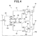
- the antenna switching unit 50 includes three switches 60, 70, and 80, and a distributor 90 that are mounted on a printed board PB.
- the switches 60, 70, and 80 serve as electronic analog switches.
- the switch 60 is a single-pole four-throw (SP4T) switch that has a single one-side terminal 61 and four other-side terminals 62 to 65. Electric power from an external source is supplied to the one-side terminal 61 during radio wave output.
- the switch 60 functions to achieve conduction between any one of the other-side terminals 62 to 65 and the one-side terminal 61 based on the switching signal CS.
- the switch 60 is configured such that, when conduction is achieved between any one of the other-side terminals and the one-side terminal 61 under the control of the control unit 21, the remaining other-side terminals are connected to terminating resistors.
- the switch 60 may correspond to an example of a "first switch.”
- the switch 70 functions as a switch that switches to either of a state in which conduction is achieved between the other-side terminal 62 of the switch 60 and the horizontally polarized wave antenna 41, and a state in which conduction is achieved between a terminal 93 of the distributor 90, described hereafter, and the horizontally polarized wave antenna 41, based on the switching signal CS sent from the control unit 21.
- the switch 70 is a single-pole double-throw (SPDT) switch that has a terminal 71 connected to the other-side terminal 62 of the switch 60, a terminal 72 connected to the terminal 93 of the distributor 90, and a terminal 73 connected to the horizontally polarized wave antenna 41.
- SPDT single-pole double-throw
- the switch 70 functions to achieve conduction between either of the terminal 71 and the terminal 72, and the terminal 73. Therefore, when conduction is to be achieved between the other-side terminal 62 of the switch 60 and the horizontally polarized wave antenna 41, the switch 70 is controlled by the control unit 21 to achieve conduction between the terminal 71 and the terminal 73. When conduction is to be achieved between the terminal 93 of the distributor 90 and the horizontally polarized wave antenna 41, the switch 70 is controlled by the control unit 21 to achieve conduction between the terminal 72 and the terminal 73.
- the switch 70 may correspond to an example of a "second switch" and the other-side terminal 62 may correspond to an example of a "first other-side terminal.”
- the switch 80 functions as a switch that switches to either of a state in which conduction is achieved between the other-side terminal 63 of the switch 60 and the vertically polarized wave antenna 42, and a state in which conduction is achieved between a terminal 94 of the distributor 90, described hereafter, and the vertically polarized wave antenna 42, based on the switching signal CS sent from the control unit 21.
- the switch 80 is a single-pole double-throw (SPDT) switch that has a terminal 81 connected to the other-side terminal 63 of the switch 60, a terminal 82 connected to the terminal 94 of the distributor 90, and a terminal 83 connected to the vertically polarized wave antenna 42.
- SPDT single-pole double-throw
- the switch 80 functions to achieve conduction between either of the terminal 81 and the terminal 82, and the terminal 83. Therefore, when conduction is to be achieved between the other-side terminal 63 of the switch 60 and the vertically polarized wave antenna 42, the switch 80 is controlled by the control unit 21 to achieve conduction between the terminal 81 and the terminal 83. When conduction is to be achieved between the terminal 94 of the distributor 90 and the vertically polarized wave antenna 42, the switch 80 is controlled by the control unit 21 to achieve conduction between the terminal 82 and the terminal 83.
- the switch 80 may correspond to an example of a "third switch" and the other-side terminal 63 may correspond to an example of a "second other-side terminal.”
- the distributor 90 has four terminals 91 to 94.
- the distributor 90 is configured as a 90-degree hybrid circuit that distributes electric power supplied from the terminal 91 or the terminal 92 to the terminal 93 and the terminal 94 with a phase difference of 90 degrees.
- the terminal 91 is connected to the other-side terminal 64 of the switch 60.
- the terminal 92 is connected to the other-side terminal 65 of the switch 60.
- the terminal 93 is connected to the terminal 72 of the switch 70.
- the terminal 94 is connected to the terminal 82 of the switch 80.
- the other-side terminal 64 may correspond to an example of a "third other-side terminal.”
- the other-side terminal 65 may correspond to an example of a "fourth other-side terminal.”
- the terminal 91 may correspond to an example of a "first distributor one-side terminal.”
- the terminal 92 may correspond to an example of a "second distributor one-side terminal.”
- the terminal 93 may correspond to an example of a "first distributor other-side terminal.”
- the terminal 94 may correspond to an example of a "second distributor other-side terminal.”
- the distributor 90 is configured such that the electric power supplied to the terminal 93 via the terminal 91 has a phase difference that is a delay by 90 degrees in relation to the electric power supplied to the terminal 94 via the terminal 91, and the electric power supplied to the terminal 94 via the terminal 92 has a phase difference that is a delay by 90 degrees in relation to the electric power supplied to the terminal 93 via the terminal 92.
- the terminal 62 of the switch 60 and the terminal 71 of the switch 70 are connected by a wiring pattern 51 on the board PB.
- the terminal 63 of the switch 60 and the terminal 81 of the switch 80 are connected by a wiring pattern 52 on the board PB.
- the terminal 64 of the switch 60 and the terminal 91 of the distributor 90 are connected by a wiring pattern 53 on the board PB.
- the terminal 65 of the switch 60 and the terminal 92 of the distributor 90 are connected by a wiring pattern 54 on the board PB.
- the terminal 93 of the distributor 90 and the terminal 72 of the switch 70 are connected by a wiring pattern 55 on the board PB.
- the terminal 94 of the distributor 90 and the terminal 82 of the switch 80 are connected by a wiring pattern 56 on the board PB.
- the antenna switching unit 50 is a wiring pattern on the board PB in which the switch 70 and the switch 80 are respectively arranged between the switch 60, and the horizontally polarized wave antenna 41 and the vertically polarized wave antenna 42.
- the distributor 90 is arranged between the switch 60, and the switch 70 and the switch 80. Therefore, the wiring pattern leading to the horizontally polarized wave antenna 41 and the wiring pattern leading to the vertically polarized wave antenna 42 can be arranged such as to be physically symmetrical on the board PB.
- the wiring pattern leading to the horizontally polarized wave antenna 41 is the wiring pattern 51 directly connecting the switch 60 and the switch 70, and the wiring patterns 53 and 55 connecting the switch 60 and the switch 70 via the distributor 90.
- the wiring pattern leading to the vertically polarized wave antenna 42 is the wiring pattern 52 directly connecting the switch 60 and the switch 80, and the wiring patterns 54 and 56 connecting the switch 60 and the switch 80 via the distributor 90.
- the four types of radio waves are the horizontally polarized waves, the vertically polarized waves, the right-handed circularly polarized waves, and the left-handed circularly polarized waves.
- the horizontally polarized radio waves are outputted as a result of electric power for radio-wave output being supplied from the transmitting/receiving unit 43 controlled by the control unit 21, via the one-side terminal 61 of the switch 60.
- the information in the RFID tag T is read based on the radio waves received from the RFID tag T based on the output.
- the vertically polarized radio waves are outputted as a result of electric power for radio-wave output being supplied from the transmitting/receiving unit 43 controlled by the control unit 21, via the one-side terminal 61 of the switch 60.
- the information in the RFID tag T is read based on the radio waves received from the RFID tag T based on the output.
- the electric power supplied to the terminal 93 via the terminal 91 has a phase difference that is a delay by 90 degrees in relation to the electric power supplied to the terminal 94 via the terminal 91.
- the phase of the electric power supplied to the horizontally polarized wave antenna 41 is delayed by 90 degrees in relation to the phase of the electric power supplied to the vertically polarized wave antenna 42, the right-handed circularly polarized radio waves are outputted.
- the information in the RFID tag T is read based on the radio waves received from the RFID tag T based on the output.
- the electric power supplied to the terminal 94 via the terminal 92 has a phase difference that is a delay by 90 degrees in relation to the electric power supplied to the terminal 93 via the terminal 92.
- the phase of the electric power supplied to the vertically polarized wave antenna 42 is delayed by 90 degrees in relation to the phase of the electric power supplied to the horizontally polarized wave antenna 41, the left-handed circularly polarized radio waves are outputted.
- the information in the RFID tag T is read based on the radio waves received from the RFID tag T based on the output.
- the switch 60 has the single one-side terminal 61 and the four other-side terminals 62 to 65.
- the distributor 90 distributes the electric power supplied via the switch 60 to the terminal 93 and the terminal 94 with a phase difference of 90 degrees.
- the switch 70 switches between the state in which conduction is achieved between the other-side terminal 62 of the switch 60 and the horizontally polarized wave antenna 41, and the state in which conduction is achieved between the terminal 93 of the distributor and the horizontally polarized wave antenna 41.
- the switch 80 switches between the state in which conduction is achieved between the other-side terminal 63 of the switch 60 and the vertically polarized wave antenna 42, and the state in which conduction is achieved between the terminal 94 of the distributor and the vertically polarized wave antenna 42.
- the control unit 21 controls the conduction state of the switches 60, 70, and 80.
- the horizontally polarized radio waves are outputted (transmitted) via the horizontally polarized wave antenna 41 when conduction is achieved between the other-side terminal 62 of the switch 60 and the horizontally polarized wave antenna 41.
- the vertically polarized radio waves are outputted (transmitted) via the vertically polarized wave antenna 42 when conduction is achieved between the other-side terminal 63 of the switch 60 and the vertically polarized wave antenna 42.
- the wiring pattern H leading from the switch 60 to the horizontally polarized wave antenna 41 and the wiring pattern V leading to the vertically polarized wave antenna 42 can be arranged such as to be physically symmetrical to each other on the printed board.
- the wiring pattern H leading to the horizontally polarized wave antenna 41 and the wiring pattern V leading to the vertically polarized wave antenna 42 can physically be wirings of equal lengths. Because phase difference attributed to differences in wiring paths is no longer required to be considered, wiring pattern design does not become complicated. Consequently, an antenna apparatus that enables simplification of wiring pattern design while enabling switching between polarized waves, such as horizontally polarized waves and vertically polarized waves, can be actualized.
- the distributor 90 applies, to the electric power supplied to the terminal 93 via the terminal 91 connected to the other-side terminal 64 of the switch 60, a phase difference that is a delay by 90 degrees in relation to the electric power supplied to the terminal 94 via the terminal 91.
- the distributor 90 applies, to the electric power supplied to the terminal 94 via the terminal 92 connected to the other-side terminal 65 of the switch 60, a phase difference that is a delay by 90 degrees in relation to the electric power supplied to the terminal 93 via the terminal 92.
- the right-handed circularly polarized radio waves can be outputted by the phase of the electric power supplied to the horizontally polarized wave antenna 41 being delayed by 90 degrees in relation to the phase of the electric power supplied to the vertically polarized wave antenna 42.
- the left-handed circularly polarized radio waves can be outputted by the phase of the electric power supplied to the vertically polarized wave antenna 42 being delayed by 90 degrees in relation to the phase of the electric power supplied to the horizontally polarized wave antenna 41. Consequently, switching can be performed not only to the horizontally polarized waves and the vertically polarized waves, but also to the two types of circularly polarized waves, the right-handed circularly polarized waves and the left-handed circularly polarized waves. Usefulness can be improved.
- a configuration in which the terminal 92 of the distributor 90 is connected to a terminating resistor (such as 50 ⁇ ), such as an antenna switching unit 50a shown in Fig. 8 is also possible.
- a switch (first switch) 60a is configured as a single-pole triple-throw (SP3T) switch that has three other-side terminals 62 to 64.
- SP3T single-pole triple-throw
- the horizontally polarized radio waves are outputted via the horizontally polarized wave antenna 41 when conduction is achieved between the terminal 71 and the terminal 73 of the switch 70, and conduction is achieved between the other-side terminal 62 of the switch 60a and the horizontally polarized wave antenna 41.
- a state enabling output of the vertically polarized radio waves via the vertically polarized wave antenna 42 is achieved when conduction is achieved between the terminal 81 and the terminal 83 of the switch 80, and conduction is achieved between the other-side terminal 63 of the switch 60a and the vertically polarized wave antenna 42.
- the electric power supplied to the terminal 93 via the terminal 91 has a phase difference that is a delay by 90 degrees in relation to the electric power supplied to the terminal 94 via the terminal 91.
- a state enabling output of the right-handed circularly polarized radio waves is achieved.
- a configuration enabling switching among three types of polarized waves, the horizontally polarized wave, the vertically polarized wave, and the right-handed circularly polarized wave can be actualized by a configuration that is simpler than the above-described configuration according to the first embodiment.
- the antenna apparatus 40a according to the present second embodiment differs from the above-described antenna apparatus according to the first embodiment in that the antenna apparatus 40a is configured to be capable of switching among four polarized waves that include two types of diagonally polarized waves in addition to the horizontally polarized wave and the vertically polarized wave. Therefore, constituent sections that are essentially identical to those of the antenna apparatus according to the first embodiment are given the same reference numbers. Descriptions thereof are omitted.
- an antenna switching unit 50b shown in Fig. 9 is used to enable switching among four polarized waves including the two types of diagonally polarized waves in addition to the horizontally polarized waves and the vertically polarized waves.
- diagonally polarized waves also referred to, hereafter, as “first diagonally polarized waves”
- first diagonally polarized waves that are generated by the phase of the electric power supplied to the horizontally polarized wave antenna 41 being delayed by 180 degrees in relation to the phase of the electric power supplied to the vertically polarized wave antenna 42
- diagonally polarized waves also referred to, hereafter, as “second diagonally polarized waves” that are generated by the phase of the electric power supplied to the horizontally polarized wave antenna 41 and the phase of the electric power supplied to the vertically polarized wave antenna 42 becoming identical are assumed.
- the antenna switching unit 50b is configured such that a phase shifter 100 is provided in the above-described antenna switching unit 50, between the switch 70 and the horizontally polarized wave antenna 42.
- the phase shifter 100 applies a delay of 90 degrees to electric power.
- conduction is achieved between the one-side terminal 61 of the switch 60 and the horizontally polarized wave antenna 41 as a result of conduction being achieved between the one-side terminal 61 and the other-side terminal 62 in the switch 60, and conduction being achieved between the terminal 71 and the terminal 73 in the switch 70.
- a state enabling output of the horizontally polarized radio waves is achieved. In this conduction state, the phase delay caused by the phase shifter 100 does not affect the switching between polarized waves.
- conduction is achieved between the one-side terminal 61 of the switch 60 and the vertically polarized wave antenna 42 as a result of conduction being achieved between the one-side terminal 61 and the other-side terminal 63 in the switch 60, and conduction being achieved between the terminal 81 and the terminal 83 in the switch 80.
- a state enabling output of the vertically polarized radio waves is achieved.
- the electric power supplied to the terminal 93 via the terminal 91 has a phase difference that is a delay of 90 degrees in relation to the electric power supplied to the terminal 94 via the terminal 91.
- the electric power supplied via the switch 70 has a phase delay of 90 degrees as a result of the phase shifter 100.
- switching can be performed not only to the horizontally polarized waves and the vertically polarized waves, but also to the diagonally polarized waves (second diagonally polarized waves) generated when the phase of the electric power supplied to the horizontally polarized wave antenna 41 and the phase of the electric power supplied to the vertically polarized wave antenna 42 become identical, and the diagonally polarized waves (first diagonally polarized waves) generated when the phase difference between the phase of the electric power supplied to the horizontally polarized wave antenna 41 and the phase of the electric power supplied to the vertically polarized wave antenna 42 is 180 degrees.
- Usefulness can be improved.
- the antenna switching unit 50b may be configured such that the phase shifter 100 is provided in the above-described antenna switching unit 50, between the switch 80 and the vertically polarized wave antenna 42.
- the phase shifter 100 applies a delay of 90 degrees to electric power.
- switching can be performed not only to the horizontally polarized waves and the vertically polarized waves, but also to the diagonally polarized waves generated when the phase of the electric power supplied to the horizontally polarized wave antenna 41 and the phase of the electric power supplied to the vertically polarized wave antenna 42 become identical, and the diagonally polarized waves generated when the phase difference between the phase of the electric power supplied to the horizontally polarized wave antenna 41 and the phase of the electric power supplied to the vertically polarized wave antenna 42 is 180 degrees.
- Usefulness can be improved.
- the antenna apparatus 40a according to the present third embodiment differs from the above-described antenna apparatus according to the second embodiment in that a phase shifter switch 110 is provided. Therefore, constituent sections that are essentially identical to those of the antenna apparatus according to the first embodiment are given the same reference numbers. Descriptions thereof are omitted.
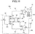
- an antenna switching unit 50c shown in Fig. 11 is used to enable switching among six polarized waves including two types of circularly polarized waves in addition to the horizontally polarized waves, the vertically polarized waves, and the two types of diagonally polarized waves.
- the antenna switching unit 50c is configured such that the phase shifter switch 110 is newly provided in the above-described antenna switching unit 50b.
- the phase shifter switch 110 functions as a switch that switches to either of a conduction state in which phase shifting by the phase shifter 100 is performed and a conduction state in which phase shifting by the phase shifter 100 is canceled, under the control of the control unit 21.
- the phase shifter switch 110 is configured as a double-pole double-throw (DPDT) switch that has a terminal connected to the terminal 73 of the switch 70, a terminal connected to the horizontally polarized wave antenna 41, and two terminals connected to the phase shifter 100.
- DPDT double-pole double-throw
- phase shifter switch 110 is controlled by the control unit 21 such that the terminal 73 of the switch 70 and the horizontally polarized wave antenna 41 are connected via the phase shifter 100.
- phase shifter switch 110 is controlled by the control unit 21 such that the terminal 73 of the switch 70 and the horizontally polarized wave antenna 41 are directly connected.
- conduction is achieved between the one-side terminal 61 of the switch 60 and the horizontally polarized wave antenna 41 when conduction is achieved between the one-side terminal 61 and the other-side terminal 62 in the switch 60, and conduction is achieved between the terminal 71 and the terminal 73 in the switch 70.
- a state enabling output of the horizontally polarized radio waves is achieved.
- conduction is achieved between the one-side terminal 61 of the switch 60 and the vertically polarized wave antenna 42 when conduction is achieved between the one-side terminal 61 and the other-side terminal 63 in the switch 60, and conduction is achieved between the terminal 81 and the terminal 83 in the switch 80.
- a state enabling output of the vertically polarized radio waves is achieved.
- the electric power supplied via the switch 70 has a phase delay of 90 degrees as a result of the phase shifter 100. Therefore, a state enabling output of the first diagonally polarized radio waves generated by the phase of the electric power supplied to the horizontally polarized wave antenna 41 being delayed by 180 degrees in relation to the phase of the electric power supplied to the vertically polarized wave antenna 42 is achieved.
- the electric power supplied via the switch 70 has a phase delay of 90 degrees as a result of the phase shifter 100. Therefore, a state enabling output of the second diagonally polarized radio waves generated by the phase of the electric power supplied to the horizontally polarized wave antenna 41 and the phase of the electric power supplied to the vertically polarized wave antenna 42 becoming identical is achieved.
- the electric power supplied to the terminal 93 via the terminal 91 has a phase difference that is a delay of 90 degrees in relation to the electric power supplied to the terminal 94 via the terminal 91. Therefore, because the phase of the electric power supplied to the horizontally polarized wave antenna 41 is delayed by 90 degrees in relation to the phase of the electric power supplied to the vertically polarized wave antenna 42, a state enabling output of the right-handed circularly polarized waves is achieved.
- the electric power supplied to the terminal 94 via the terminal 92 has a phase difference that is a delay of 90 degrees in relation to the electric power supplied to the terminal 93 via the terminal 92. Therefore, because the phase of the electric power supplied to the vertically polarized wave antenna 42 is delayed by 90 degrees in relation to the phase of the electric power supplied to the horizontally polarized wave antenna 41, a state enabling output of the left-handed circularly polarized waves is achieved.
- switching can be performed from the state enabling output of the diagonally polarized radio waves generated by the phase of the electric power supplied to the horizontally polarized wave antenna 41 and the phase of the electric power supplied to the vertically polarized wave antenna 42 becoming identical as a result of phase shifting by the phase shifter 100, to the state enabling output of the circularly polarized radio waves generated by the phase difference between the phase of the electric power supplied to the horizontally polarized wave antenna 41 and the phase of the electric power supplied to the vertically polarized wave antenna 42 becoming 90 degrees as a result of phase shifting by the phase shifter 100 being canceled.
- switching can be performed from the state enabling output of the diagonally polarized radio waves generated by the phase difference between the phase of the electric power supplied to the horizontally polarized wave antenna 41 and the phase of the electric power supplied to the vertically polarized wave antenna 42 becoming 180 degrees as a result of phase shifting by the phase shifter 100, to the state enabling output of the circularly polarized radio waves generated by the phase difference between the phase of the electric power supplied to the horizontally polarized wave antenna 41 and the phase of the electric power supplied to the vertically polarized wave antenna 42 becoming 90 degrees as a result of phase shifting by the phase shifter 100 being canceled. Consequently, switching can be performed not only to the horizontally polarized waves, the vertically polarized waves, and the diagonally polarized waves, but also to the circularly polarized waves. Usefulness can be further improved.
- phase shifter switch 120 is a single-pole double-throw (SPDT) switch that has a single terminal 121 to which electric power is supplied during radio wave output, a terminal 122 connected to the phase shifter 100, and a terminal 123 directly connected to the phase shifter switch 130.
- SPDT single-pole double-throw
- the phase shifter switch 120 functions to achieve conduction between either of the terminals 122 and 123, and the single terminal 121, under the control of the control unit 21.
- the phase shifter switch 130 is a single-pole double-throw (SPDT) switch that has a terminal 131 connected to the horizontally polarized wave antenna 41, a terminal 132 connected to the phase shifter 100, and a terminal 133 directly connected to the phase shifter switch 120.
- SPDT single-pole double-throw
- the phase shifter switch 130 functions to achieve conduction between either of the terminals 132 and 133, and the terminal 131, under the control of the control unit 21.
- switching can be performed to either of the conduction state in which phase shifting by the phase shifter 100 is performed and the conduction state in which phase shifting by the phase shifter 100 is canceled, based on the conduction state of the phase shifter switches 120 and 130 controlled by the control unit 21.
- the conduction state in which phase shifting by the phase shifter 100 is canceled is indicated by conduction being achieved between the terminal 123 and the terminal 121 in the phase shifter switch 120, and conduction being achieved between the terminal 133 and the terminal 131 in the phase shifter switch 130.
- the present invention is not limited to the above-described embodiments.
- the present invention may be realized in the following manner.
- the antenna apparatus of the present invention is not limited to being mounted in the above-described mobile-type information terminal providing both a function as an RFID reader/writer and a function as an information code reader.
- the antenna apparatus may be mounted in an information terminal that provides only the function for reading the RFID tag T.
- the antenna apparatus may be mounted in an information terminal further providing other functions.
- the antenna apparatus of the present invention is not limited to being mounted in a mobile-type information terminal, and may be mounted in a stationary-type information terminal.
Landscapes
- Engineering & Computer Science (AREA)
- Computer Networks & Wireless Communication (AREA)
- Signal Processing (AREA)
- Variable-Direction Aerials And Aerial Arrays (AREA)
Abstract

Description
- The present invention relates to an antenna apparatus for communicating with a noncontact communication medium using electromagnetic waves.
- Systems that perform noncontact information communication between information media via radio waves (electromagnetic waves) are currently in heavy use. A radio frequency identifier (RFID) tag is a typical example of such information media.
- Conventionally, in a reading apparatus that reads the RFID tags, circularly polarized waves that enable reading regardless of the orientation (arrangement direction) of the RFID tag are often used.
- However, the circularly polarized waves are generated by electric power with a phase difference of 90 degrees being equally distributed between a horizontally polarized wave antenna and a vertically polarized wave antenna. Therefore, the electric power is halved, compared to linearly polarized waves such as horizontally polarized waves and vertically polarized waves. A problem occurs in that communication distance decreases to about 70%. Meanwhile, should a linearly polarized wave switching method, in which power supply is switched between that to the horizontally polarized wave antenna and that to the vertically polarized wave antenna based on time, be used to ensure communication distance, when either of the polarized waves are being outputted, the RFID tag at the orientation corresponding to the other of the polarized waves cannot be read.
- Therefore, a problem occurs in that, in an environment in which a plurality of RFID tags of which the orientations are difficult to identify are to be read, reading of the RFID tags becomes time consuming, compared to cases in which the circularly polarized waves are used.
- Therefore, a reading apparatus has been proposed that enables a user to switch to circularly polarized wave output in cases in which RFID tags arranged at various orientations are to be read at high speed, linearly polarized wave output in cases in which communication distance is to be increased, horizontally polarized wave output in cases in which an RFID tag oriented in the horizontal direction is to be read at high speed by long-distance communication, and vertically polarized wave output in cases in which an RFID tag oriented in the vertical direction is to be read at high speed by long-distance communication, with a single reading apparatus.
- For example, in a switching apparatus for multi-polarization disclosed in PTL 1, below, a first switch is connected between a first input/output terminal, a third input/output terminal, and a 90-degree hybrid circuit. A second switch is connected between a second input/output terminal, a fourth input/output terminal, and the 90-degree hybrid circuit. Switching between linearly polarized waves and circularly polarized waves is performed based on switching of conduction states by operation of both switches. In particular, in the switching apparatus for multi-polarization disclosed in PTL 1, a configuration is disclosed in which the first switch is connected between the input terminal (first input/output terminal) and the 90-degree hybrid circuit, and the second switch is connected between one of the output terminals (second input/output terminal), the other of the output terminals (third input/output terminal), the first switch, and the 90-degree hybrid circuit, as a configuration for providing a single input terminal.
- [PTL 1]
JP-A-2008-219778 - A phase difference of 90 degrees is required to be provided between the electric power supplied to the output terminal connected to the horizontally polarized wave antenna and the electric power supplied to the output terminal connected to the vertically polarized wave antenna, to output circularly polarized waves. However, in configurations such as that described above, a wiring pattern leading to the horizontally polarized wave antenna (a wiring pattern from the input-side terminal to one output-side terminal) and a wiring pattern leading to the vertically polarized wave antenna (a wiring pattern from the input-side terminal to the other output-side terminal) become asymmetrical. Therefore, while the wiring patterns are required to be designed taking into consideration phase differences attributed to the differences in wiring paths, trial productions including adjustment of the wiring patterns and the like become necessary because such phase differences are difficult to predict at the designing stage. A problem occurs in that wiring pattern design becomes complicated.
- Taking into consideration the foregoing problems, providing an antenna apparatus that enables simplification of wiring pattern design while enabling switching between polarized waves, such as horizontally polarized waves and vertically polarized waves, is desired.
- To achieve the above-described object, a typical example of an antenna apparatus (40a) includes:
- a horizontally polarized wave antenna (41) for emitting horizontally polarized waves as radio waves;
- a vertically polarized wave antenna (42) for emitting vertically polarized waves as radio waves;
- a first switch (60, 60a) that has a single one-side terminal (61) to which electric power from an outside source is supplied during output of the radio waves and a plurality of other-side terminals (62 to 65), and achieves conduction between any one of the plurality of other-side terminals and the one-side terminal;
- a distributor (90) that has a first distributor other-side terminal (93) and a second distributor other-side terminal (94), and distributes the electric power supplied via the first switch to the first distributor other-side terminal and the second distributor other-side terminal with a phase difference of 90 degrees;
- a second switch (70) that switches to either of a state in which conduction is achieved between a first other-side terminal of the first switch and the horizontally polarized wave antenna, and a state in which conduction is achieved between the first distributor other-side terminal of the distributor and the horizontally polarized wave antenna;
- a third switch (80) that switches to either of a state in which conduction is achieved between a second other-side terminal of the first switch and the vertically polarized wave antenna, and a state in which conduction is achieved between the second distributor other-side terminal of the distributor and the vertically polarized wave antenna; and
- a control unit that controls the conduction state of the first switch, the second switch, and the third switch such as to switch the polarized waves emitted as the radio waves, using at least either of the horizontally polarized wave antenna and the vertically polarized wave antenna.
- Reference numbers within the parentheses, above, indicate corresponding relationships with specific means according to embodiments described hereafter.
- In the typical example, the conduction state of the first, second, and third switches, that is, the electrical connection between the terminals of the switches is controlled by the control unit.
- As a result, in a state in which electric power is supplied via the one-side terminal, horizontally polarized radio waves are outputted via the horizontally polarized wave antenna when conduction is achieved between the first other-side terminal of the first switch and the horizontally polarized wave antenna. Meanwhile, vertically polarized radio waves are outputted via the vertically polarized wave antenna when conduction is achieved between the second other-side terminal of the first switch and the vertically polarized wave antenna. In addition, based on control of the switches by the control unit, when electric power is supplied to the distributor via the first switch, the horizontally polarized radio waves outputted via the horizontally polarized wave antenna and the vertically polarized radio waves outputted via the vertically polarized wave antenna have a phase difference of 90 degrees. Therefore, circularly polarized radio waves are outputted.
- In particular, a wiring pattern is formed in which the second switch and the third switch are respectively arranged between the first switch, and the horizontally polarized wave antenna and the vertically polarized wave antenna, and the distributor is arranged between the first switch, and the second switch and the third switch. Therefore, the wiring pattern leading to the horizontally polarized wave antenna and the wiring pattern leading to the vertically polarized wave antenna can be arranged such as to be physically symmetrical on a printed board. Consequently, an antenna apparatus that enables simplification of wiring pattern design while enabling switching between polarized waves, such as horizontally polarized waves and vertically polarized waves, can be actualized.
- In a favorable example, the distributor applies a phase difference to the electric power supplied to the first distributor other-side terminal via a first distributor one-side terminal connected to a third other-side terminal of the first switch that is a delay of 90 degrees in relation to the electric power supplied to the second distributor other-side terminal via the first distributor one-side terminal. The distributor applies a phase difference to the electric power supplied to the second distributor other-side terminal via a second distributor one-side terminal connected to a fourth other-side terminal of the first switch that is a delay of 90 degrees in relation to the electric power supplied to the first distributor other-side terminal via the second distributor one-side terminal.
- Therefore, right-handed circularly polarized radio waves can be outputted by the phase of the electric power supplied to the horizontally polarized wave antenna being delayed by 90 degrees in relation to the phase of the electric power supplied to the vertically polarized wave antenna. In addition, left-handed circularly polarized radio waves can be outputted by the phase of the electric power supplied to the vertically polarized wave antenna being delayed by 90 degrees in relation to the phase of the electric power supplied to the horizontally polarized wave antenna. Consequently, switching not only to the horizontally polarized wave and the vertically polarized wave, but also to the two types of circularly polarized waves, the right-handed circularly polarized waves and the left-handed circularly polarized waves. Usefulness can be improved.
- In another favorable example, a phase shifter that applies a delay of 90 degrees to electric power is provided between either of the second switch and the horizontally polarized wave antenna, and the third switch and the vertically polarized wave antenna.
- As a result, switching can be performed not only to the horizontally polarized wave and the vertically polarized wave, but also to diagonally polarized waves generated when the phase of the electric power supplied to the horizontally polarized wave antenna and the phase of the electric power supplied to the vertically polarized wave antenna become identical, and diagonally polarized waves generated when the phase difference between the phase of the electric power supplied to the horizontally polarized wave antenna and the phase of the electric power supplied to the vertically polarized wave antenna is 180 degrees. Usefulness can be improved.
- In still another favorable example, a conduction state of a phase shifter switch is controlled by the control unit. The phase shifter switch switches to either of a conduction state in which phase shifting by the phase shifter is performed and a conduction state in which phase shifting by the phase shifter is canceled.
- Therefore, switching can be performed from the state enabling output of the diagonally polarized radio waves generated by the phase of the electric power supplied to the horizontally polarized wave antenna and the phase of the electric power supplied to the vertically polarized wave antenna becoming identical as a result of phase shifting by the phase shifter, to the state enabling output of the circularly polarized radio waves generated by the phase difference between the phase of the electric power supplied to the horizontally polarized wave antenna and the phase of the electric power supplied to the vertically polarized wave antenna becoming 90 degrees as a result of phase shifting by the phase shifter being canceled. In addition, switching can be performed from the state enabling output of the diagonally polarized radio waves generated by the phase difference between the phase of the electric power supplied to the horizontally polarized wave antenna and the phase of the electric power supplied to the vertically polarized wave antenna becoming 180 degrees as a result of phase shifting by the phase shifter, to the state enabling output of the circularly polarized radio waves generated by the phase difference between the phase of the electric power supplied to the horizontally polarized wave antenna and the phase of the electric power supplied to the vertically polarized wave antenna becoming 90 degrees as a result of phase shifting by the phase shifter being canceled. Consequently, switching can be performed not only to the horizontally polarized waves, the vertically polarized waves, and the diagonally polarized waves, but also to the circularly polarized waves. Usefulness can be further improved.
- In the accompanying drawings:
-
Fig. 1A is a planar view of a configuration overview of a mobile terminal according to a first embodiment; -
Fig. 1B is a side view of a configuration overview of the mobile terminal according to the first embodiment; -
Fig. 2A is a block diagram of an example of an electrical configuration of the mobile terminal according to the first embodiment; -
Fig. 2B is a block diagram schematically showing an example of an information code reading unit -
Fig. 3 is a block diagram schematically showing an example of a noncontact communicating unit; -
Fig. 4 is a circuit diagram schematically showing switches and wiring patterns configuring an antenna switching unit; -
Fig. 5 is a circuit diagram schematically showing a configuration of a first switch; -
Fig. 6A is an explanatory diagram of a conduction state for linearly polarized waves according to the first embodiment, particularly showing a conduction state for switching to horizontally polarized waves; -
Fig. 6B is an explanatory diagram of a conduction state for linearly polarized waves according to the first embodiment, particularly showing a conduction state for switching to vertically polarized waves; -
Fig. 7A is an explanatory diagram of a conduction state for circularly polarized waves according to the first embodiment, particularly showing a conduction state for switching to right-handed circularly polarized waves; -
Fig. 7B is an explanatory diagram of a conduction state for circularly polarized waves according to the first embodiment, particularly showing a conduction state for switching to left-handed circularly polarized waves; -
Fig. 8 is a circuit diagram schematically showing the switches and wiring patterns configuring the antenna switching unit of an antenna apparatus of a variation example according to the first embodiment; -
Fig. 9 is a circuit diagram schematically showing switches and wiring patterns configuring an antenna switching unit of an antenna apparatus according to a second embodiment; -
Fig. 10A is an explanatory diagram of a conduction state for diagonally polarized waves according to the second embodiment, particularly showing a conduction state for switching to first diagonally polarized waves; -
Fig. 10B is an explanatory diagram of a conduction state for diagonally polarized waves according to the second embodiment, particularly showing a conduction state for switching to second diagonally polarized waves; -
Fig. 11 is a circuit diagram schematically showing switches and wiring patterns configuring an antenna switching unit of an antenna apparatus according to a third embodiment; -
Fig. 12A is an explanatory diagram of a conduction state for diagonally polarized waves according to the third embodiment, particularly showing a conduction state for switching to first diagonally polarized waves; -
Fig. 12B is an explanatory diagram of a conduction state for diagonally polarized waves according to the third embodiment, particularly showing a conduction state for switching to second diagonally polarized waves; -
Fig. 13A is an explanatory diagram of a conduction state for circularly polarized waves according to the third embodiment, particularly showing a conduction state for switching to right-handed circularly polarized waves; -
Fig. 13B is an explanatory diagram of a conduction state for circularly polarized waves according to the third embodiment, particularly showing a conduction state for switching to left-handed circularly polarized waves; and -
Fig. 14 is a circuit diagram of a circuit for switching a path passing through a 90-degree phase shift line. - Various embodiments of an antenna apparatus of the present invention will hereinafter be described with reference to the accompanying drawings.
- First, a first embodiment realizing a mobile terminal that includes an antenna apparatus of the present invention will be described with reference to the drawings.
- A
mobile terminal 10 according to the present embodiment is configured as a mobile-type information terminal that is carried by a user and used in various locations. Themobile terminal 10 provides a function as an information code reader, in addition to a function as an RFID tag reader/writer, and is configured to be capable of reading based on two methods. The RFID tag reader/writer reads and writes information stored on an RFID tag (noncontact communication medium) T using radio waves (electromagnetic waves) transmitted and received via an antenna as a medium. The information code reader reads information codes, such as barcodes and two-dimensional codes such as QR codes (registered trademark). - As shown in
Fig. 1A and Fig. 1B , the exterior of themobile terminal 10 is formed by anelongated housing 11. Thehousing 11 is composed of anupper case 11a and alower case 11b that are assembled together. Theupper case 11a and thelower case 11b are made of a synthetic resin material, such as acrylonitrile butadiene styrene (ABS) resin. In addition, akey operating unit 25, adisplay unit 24, and the like are arranged in theupper case 11a. Thekey operating unit 25 includes function keys, a numeric key pad, and the like that are operated to input predetermined information. Thedisplay unit 24 displays predetermined information. Areading opening 12 that opens downward is provided in thelower case 11b. - As shown in
Fig. 2A , acontrol unit 21 is provided within thehousing 11 of themobile terminal 10. Thecontrol unit 21 controls the overallmobile terminal 10. Thecontrol unit 21 is mainly configured by amicrocomputer 21A. That is, themicrocomputer 21A has a central processing unit (CPU), a system bus, an input/output interface, and the like (not shown). Themicrocomputer 21A, together with anexternal memory 22, configures an information processing unit. Thememory 22 may be provided within thecontrol unit 21 or may be included within themicrocomputer 21A. - The
memory 22 functions as a "non-transient computer readable medium." A predetermined program for performing a reading process to read the RFID tag T by noncontact communication via radio waves (electromagnetic waves), and other necessary programs are stored in thememory 22 in advance, such as to be executable by thecontrol unit 21. Therefore, for example, themicrocomputer 21A (that is, the CPU) runs the program for the reading process based on an interactive request from the user. As a result of the program being executed, themicrocomputer 21A is able to generate switching signals CS for switching operations of switches, described hereafter. - In addition, a light-emitting diode (LED) 23, a
display unit 24, thekey operating unit 25, avibrator 26, abuzzer 27, anexternal interface 28, and the like are connected to thecontrol unit 21. - The
key operating unit 25 is configured to provide thecontrol unit 21 with operating signals. Thecontrol unit 21 receives the operating signals and performs operations based on the content of the operating signals. In addition, theLED 23, thedisplay unit 24, thevibrator 26, and thebuzzer 27 are configured to be controlled by thecontrol unit 21. TheLED 23, thedisplay unit 24, thevibrator 26, and thebuzzer 27 are each operated based on commands received from thecontrol unit 21. Furthermore, theexternal interface 28 is configured as an interface for performing data communication with external apparatuses and the like. Theexternal interface 28 is configured to perform communication process in cooperation with thecontrol unit 21. Moreover, a power supply unit (not shown) is provided within thehousing 11. Electric power is supplied to thecontrol unit 21 and various electrical components by the power supply unit, a battery, or the like. - In addition, an information
code reading unit 30 and anoncontact communicating unit 40 are connected to thecontrol unit 21. - First, the information
code reading unit 30 will be described with reference toFig. 2B . - The information
code reading unit 30 functions to optically read an information code. As shown inFig. 2B , the informationcode reading unit 30 is configured to include alight receiving sensor 33, animage forming lens 32, an illuminatingunit 32, and the like. Thelight receiving sensor 33 is composed of a charge-coupled device (CCD) area sensor. The illuminatingunit 32 is composed of a plurality of LEDs, a lens, and the like. The informationcode reading unit 30 functions to read an information code C (a bar code, a two-dimensional code, or the like) attached to a reading target R, in cooperation with thecontrol unit 21. - When the information
code reading unit 30 performs reading, first, the illuminatingunit 31 that has received a command from thecontrol unit 21 emits illumination light Lf. The illumination light Lf passes through thereading opening 12 and is irradiated onto the reading target R. Then, reflected light Lr, which is the illumination light Lf reflected by the information code C, passes through thereading opening 12 and is taken into the apparatus. The reflected light Lr then passes through theimage forming lens 32 and is received by thelight receiving sensor 33. Theimage forming lens 32 that is disposed between the readingopening 12 and thelight receiving sensor 33 is configured to form an image of the information code C on thelight receiving sensor 33. Thelight receiving sensor 33 outputs a light reception signal based on the image of the information code C. The light reception signal outputted from thelight receiving sensor 33 is stored in the memory 22 (seeFig. 2A ) as image data, and is used for a decoding process to acquire information included in the information code C. The informationcode reading unit 30 is provided with an amplifier circuit that amplifies the signal from thelight receiving sensor 33, an analog-to-digital (AD) converter circuit that converts the amplified signal to a digital signal, and the like. However, these circuits are omitted from the drawings. - Next, the
noncontact communicating unit 40 will be described with reference toFig. 3 . - The
noncontact communicating unit 40 functions to perform noncontact communication (wireless communication) with the RFID tag T by radio waves (electromagnetic waves), in cooperation with thecontrol unit 21. Thenoncontact communicating unit 40 also functions to read data stored in the RFID tag T or write data in the RFID tag T. Thenoncontact communicating unit 40 is configured as anantenna apparatus 40a together with thecontrol unit 21, as a circuit that performs transmission based on a publicly known radio wave format. As schematically shown inFig. 3 , a horizontally polarized wave antenna 41 (also seeFig. 1A and Fig. 1B ), a vertically polarized wave antenna 42 (also seeFig. 1A and Fig. 1B ), a transmitting/receivingunit 43, and anantenna switching unit 50 are provided. - The horizontally polarized
wave antenna 41 and the vertically polarizedwave antenna 42 are publicly known antennas of which respective polarization planes are perpendicular to each other. The horizontally polarizedwave antenna 41 and the vertically polarizedwave antenna 42 are respectively configured to be capable of transmitting and receiving horizontally polarized radio waves and vertically polarized radio waves. That is, theantenna apparatus 40a is configured to be capable of switching between a plurality of types of radio waves (electromagnetic waves) having differing polarization planes, and transmitting and receiving the plurality of types of radio waves (electromagnetic waves). - For example, the horizontally polarized
wave antenna 41 and the vertically polarizedwave antenna 42 may be configured as a dual-feed patch antenna or a cross-dipole antenna. - The transmitting/receiving
unit 43 is configured such that, under the control of thecontrol unit 21, predetermined electric power is supplied to at least either of the horizontally polarizedwave antenna 41 and the vertically polarizedwave antenna 42 via theantenna switching unit 50 during output of radio waves based on transmission data, and electric power based on reception data is supplied via theantenna switching unit 50 during reception of the reception data. Specifically, the transmitting/receivingunit 43 is configured to include atransmission circuit 43A, areception circuit 43B, amatching circuit 43C, and the like. - The
transmission circuit 43A is configured to have a publicly known circuit configuration composed of a carrier oscillator, an encoding unit, an amplifier, a transmitting unit filter, a modulating unit, and the like. Thetransmission circuit 43A has a configuration in which carrier waves of a predetermined frequency are outputted from the carrier oscillator. In addition, the encoding unit is connected to thecontrol unit 21. The encoding unit encodes the transmission data outputted from thecontrol unit 21 and outputs the encoded transmission data to the modulating unit. The modulating unit generates a modulated signal by modulating the carrier waves from the carrier oscillator, and carrier waves outputted from the carrier oscillator that is a portion in which the transmission data from the encoding unit is inputted, by amplitude shift keying (ASK) modulation using an encoded transmission code (modulation signal) outputted from the encoding unit during command transmission to a communication subject. The modulating unit then outputs the generated modulated signal to the amplifier. The amplifier amplifies the input signal (the modulated signal modulated by the modulating unit) at a predetermined gain and outputs the amplified signal to the transmitting unit filter. The transmitting unit filter outputs, to theantenna switching unit 50 via thematching circuit 43C, a transmission signal obtained by filtering the amplified signal from the amplifier. When the transmission signal is outputted to theantenna switching unit 50 in this way, the transmission signal is emitted outside from at least either of the horizontally polarizedwave antenna 41 and the vertically polarizedwave antenna 42 as radio waves (electromagnetic waves). - Meanwhile, the radio waves (electromagnetic waves) received as a response signal via the
antenna switching unit 50 as a result of being received by at least either of the horizontally polarizedwave antenna 41 and the vertically polarizedwave antenna 42 are inputted to thereception circuit 43B via thematching circuit 43C. Thereception circuit 43B is configured by a receiving unit filter, an amplifier, a demodulating unit, a binarization processing unit, a decoding unit, and the like. After the response signal received via theantenna switching unit 50 is filtered by the receiving unit filter, the filtered signal is amplified by the amplifier, and the amplified signal is demodulated by the demodulating unit. Then, the demodulated signal waveform is binarized by the binarization processing unit and decoded by the decoding unit. The decoded signal is then outputted to thecontrol unit 21 as reception data. - The
antenna switching unit 50 functions as a multi-polarization switching means. Theantenna switching unit 50 is electrically connected to the transmitting/receivingunit 43, and to the horizontally polarizedwave antenna 41 and the vertically polarizedwave antenna 42 in a selective manner, based on the switching signal CS sent from thecontrol unit 21. Theantenna switching unit 50 thereby switches the polarization planes of the radio waves to be transmitted and received, or in other words, switches between polarized waves. According to the present embodiment, theantenna switching unit 50 is configured to be capable of switching among a total of four types of polarized waves that are two types of linearly polarized waves and two types of circularly polarized waves. The two types of linearly polarized waves are horizontally polarized waves and vertically polarized waves. The two types of circularly polarized waves are right-handed circularly polarized waves and left-handed circularly polarized waves. As shown inFig. 4 , theantenna switching unit 50 includes threeswitches distributor 90 that are mounted on a printed board PB. Theswitches - As shown in
Fig. 4 andFig. 5 , theswitch 60 is a single-pole four-throw (SP4T) switch that has a single one-side terminal 61 and four other-side terminals 62 to 65. Electric power from an external source is supplied to the one-side terminal 61 during radio wave output. Theswitch 60 functions to achieve conduction between any one of the other-side terminals 62 to 65 and the one-side terminal 61 based on the switching signal CS. In particular, according to the present embodiment, asFig. 5 clearly indicates, theswitch 60 is configured such that, when conduction is achieved between any one of the other-side terminals and the one-side terminal 61 under the control of thecontrol unit 21, the remaining other-side terminals are connected to terminating resistors. In the example inFig. 5 , a state in which the other-side terminal 62 and the one-side terminal 61 are connected, and the remaining other-side terminals 63 to 65 are connected to terminating resistors having a resistance of 50 Ω, under the control of thecontrol unit 21, is shown. Theswitch 60 may correspond to an example of a "first switch." - The
switch 70 functions as a switch that switches to either of a state in which conduction is achieved between the other-side terminal 62 of theswitch 60 and the horizontally polarizedwave antenna 41, and a state in which conduction is achieved between a terminal 93 of thedistributor 90, described hereafter, and the horizontally polarizedwave antenna 41, based on the switching signal CS sent from thecontrol unit 21. Theswitch 70 is a single-pole double-throw (SPDT) switch that has a terminal 71 connected to the other-side terminal 62 of theswitch 60, a terminal 72 connected to the terminal 93 of thedistributor 90, and a terminal 73 connected to the horizontally polarizedwave antenna 41. Theswitch 70 functions to achieve conduction between either of the terminal 71 and the terminal 72, and the terminal 73. Therefore, when conduction is to be achieved between the other-side terminal 62 of theswitch 60 and the horizontally polarizedwave antenna 41, theswitch 70 is controlled by thecontrol unit 21 to achieve conduction between the terminal 71 and the terminal 73. When conduction is to be achieved between the terminal 93 of thedistributor 90 and the horizontally polarizedwave antenna 41, theswitch 70 is controlled by thecontrol unit 21 to achieve conduction between the terminal 72 and the terminal 73. Theswitch 70 may correspond to an example of a "second switch" and the other-side terminal 62 may correspond to an example of a "first other-side terminal." - The
switch 80 functions as a switch that switches to either of a state in which conduction is achieved between the other-side terminal 63 of theswitch 60 and the vertically polarizedwave antenna 42, and a state in which conduction is achieved between a terminal 94 of thedistributor 90, described hereafter, and the vertically polarizedwave antenna 42, based on the switching signal CS sent from thecontrol unit 21. Theswitch 80 is a single-pole double-throw (SPDT) switch that has a terminal 81 connected to the other-side terminal 63 of theswitch 60, a terminal 82 connected to theterminal 94 of thedistributor 90, and a terminal 83 connected to the vertically polarizedwave antenna 42. Theswitch 80 functions to achieve conduction between either of the terminal 81 and the terminal 82, and the terminal 83. Therefore, when conduction is to be achieved between the other-side terminal 63 of theswitch 60 and the vertically polarizedwave antenna 42, theswitch 80 is controlled by thecontrol unit 21 to achieve conduction between the terminal 81 and the terminal 83. When conduction is to be achieved between the terminal 94 of thedistributor 90 and the vertically polarizedwave antenna 42, theswitch 80 is controlled by thecontrol unit 21 to achieve conduction between the terminal 82 and the terminal 83. Theswitch 80 may correspond to an example of a "third switch" and the other-side terminal 63 may correspond to an example of a "second other-side terminal." - The
distributor 90 has fourterminals 91 to 94. Thedistributor 90 is configured as a 90-degree hybrid circuit that distributes electric power supplied from the terminal 91 or the terminal 92 to the terminal 93 and the terminal 94 with a phase difference of 90 degrees. In addition, the terminal 91 is connected to the other-side terminal 64 of theswitch 60. The terminal 92 is connected to the other-side terminal 65 of theswitch 60. The terminal 93 is connected to theterminal 72 of theswitch 70. The terminal 94 is connected to theterminal 82 of theswitch 80. The other-side terminal 64 may correspond to an example of a "third other-side terminal." The other-side terminal 65 may correspond to an example of a "fourth other-side terminal." In addition, the terminal 91 may correspond to an example of a "first distributor one-side terminal." The terminal 92 may correspond to an example of a "second distributor one-side terminal." The terminal 93 may correspond to an example of a "first distributor other-side terminal." The terminal 94 may correspond to an example of a "second distributor other-side terminal." - In particular, according to the present embodiment, the
distributor 90 is configured such that the electric power supplied to the terminal 93 via the terminal 91 has a phase difference that is a delay by 90 degrees in relation to the electric power supplied to the terminal 94 via the terminal 91, and the electric power supplied to the terminal 94 via the terminal 92 has a phase difference that is a delay by 90 degrees in relation to the electric power supplied to the terminal 93 via theterminal 92. - Furthermore, as shown in
Fig. 4 , theterminal 62 of theswitch 60 and theterminal 71 of theswitch 70 are connected by awiring pattern 51 on the board PB. The terminal 63 of theswitch 60 and theterminal 81 of theswitch 80 are connected by awiring pattern 52 on the board PB. In addition, theterminal 64 of theswitch 60 and theterminal 91 of thedistributor 90 are connected by awiring pattern 53 on the board PB. The terminal 65 of theswitch 60 and theterminal 92 of thedistributor 90 are connected by awiring pattern 54 on the board PB. Moreover, the terminal 93 of thedistributor 90 and theterminal 72 of theswitch 70 are connected by awiring pattern 55 on the board PB. The terminal 94 of thedistributor 90 and theterminal 82 of theswitch 80 are connected by awiring pattern 56 on the board PB. - In this way, the
antenna switching unit 50 is a wiring pattern on the board PB in which theswitch 70 and theswitch 80 are respectively arranged between theswitch 60, and the horizontally polarizedwave antenna 41 and the vertically polarizedwave antenna 42. Thedistributor 90 is arranged between theswitch 60, and theswitch 70 and theswitch 80. Therefore, the wiring pattern leading to the horizontally polarizedwave antenna 41 and the wiring pattern leading to the vertically polarizedwave antenna 42 can be arranged such as to be physically symmetrical on the board PB. The wiring pattern leading to the horizontally polarizedwave antenna 41 is thewiring pattern 51 directly connecting theswitch 60 and theswitch 70, and thewiring patterns switch 60 and theswitch 70 via thedistributor 90. In addition, the wiring pattern leading to the vertically polarizedwave antenna 42 is thewiring pattern 52 directly connecting theswitch 60 and theswitch 80, and thewiring patterns switch 60 and theswitch 80 via thedistributor 90. - Next, control of the
antenna switching unit 50 by thecontrol unit 21 to selectively switch among the total of four types of radio waves (polarization planes thereof) as the radio waves to be transmitted and received will be described with reference toFig. 6A, Fig. 6B ,Fig. 7A, and Fig. 7B . The four types of radio waves are the horizontally polarized waves, the vertically polarized waves, the right-handed circularly polarized waves, and the left-handed circularly polarized waves. - First, a case in which the RFID tag T is read through use of the horizontally polarized waves will be described with reference to
Fig. 6A . In this case, based on the switching signal CS sent from thecontrol unit 21, as shown inFig. 6A , conduction is achieved between the one-side terminal 61 and the other-side terminal 62 in theswitch 60, and conduction is achieved between the terminal 71 and the terminal 73 in theswitch 70. As a result, conduction is achieved between the one-side terminal 61 of theswitch 60 and the horizontally polarizedwave antenna 41. In this conduction state, the horizontally polarized radio waves are outputted as a result of electric power for radio-wave output being supplied from the transmitting/receivingunit 43 controlled by thecontrol unit 21, via the one-side terminal 61 of theswitch 60. The information in the RFID tag T is read based on the radio waves received from the RFID tag T based on the output. - Next, a case in which the RFID tag T is read through use of the vertically polarized waves will be described with reference to
Fig. 6B . In this case, based on the switching signal CS sent from thecontrol unit 21, as shown inFig. 6B , conduction is achieved between the one-side terminal 61 and the other-side terminal 63 in theswitch 60, and conduction is achieved between the terminal 81 and the terminal 83 in theswitch 80. As a result, conduction is achieved between the one-side terminal 61 of theswitch 60 and the vertically polarizedwave antenna 42. In this conduction state, the vertically polarized radio waves are outputted as a result of electric power for radio-wave output being supplied from the transmitting/receivingunit 43 controlled by thecontrol unit 21, via the one-side terminal 61 of theswitch 60. The information in the RFID tag T is read based on the radio waves received from the RFID tag T based on the output. - Next, a case in which the RFID tag T is read through use of the right-handed circularly polarized waves will be described with reference to
Fig. 7A . In this case, based on the switching signal CS sent from thecontrol unit 21, as shown inFig. 7A , conduction is achieved between the one-side terminal 61 and the other-side terminal 64 in theswitch 60, conduction is achieved between the terminal 72 and the terminal 73 in theswitch 70, and conduction is achieved between the terminal 82 and the terminal 83 in theswitch 80. In this conduction state, as a result of electric power for radio-wave output being supplied from the transmitting/receivingunit 43 controlled by thecontrol unit 21, via the one-side terminal 61 of theswitch 60, the electric power supplied to the terminal 93 via the terminal 91 has a phase difference that is a delay by 90 degrees in relation to the electric power supplied to the terminal 94 via theterminal 91. As a result, because the phase of the electric power supplied to the horizontally polarizedwave antenna 41 is delayed by 90 degrees in relation to the phase of the electric power supplied to the vertically polarizedwave antenna 42, the right-handed circularly polarized radio waves are outputted. The information in the RFID tag T is read based on the radio waves received from the RFID tag T based on the output. - Next, a case in which the RFID tag T is read through use of the left-handed circularly polarized waves will be described with reference to
Fig. 7B . In this case, based on the switching signal CS sent from thecontrol unit 21, as shown inFig. 7B , conduction is achieved between the one-side terminal 61 and the other-side terminal 65 in theswitch 60, conduction is achieved between the terminal 72 and the terminal 73 in theswitch 70, and conduction is achieved between the terminal 82 and the terminal 83 in theswitch 80. In this conduction state, as a result of electric power for radio-wave output being supplied from the transmitting/receivingunit 43 controlled by thecontrol unit 21, via the one-side terminal 61 of theswitch 60, the electric power supplied to the terminal 94 via the terminal 92 has a phase difference that is a delay by 90 degrees in relation to the electric power supplied to the terminal 93 via theterminal 92. As a result, because the phase of the electric power supplied to the vertically polarizedwave antenna 42 is delayed by 90 degrees in relation to the phase of the electric power supplied to the horizontally polarizedwave antenna 41, the left-handed circularly polarized radio waves are outputted. The information in the RFID tag T is read based on the radio waves received from the RFID tag T based on the output. - As described above, in the
antenna apparatus 40a according to the present embodiment, theswitch 60, thedistributor 90, theswitch 70, theswitch 80, and thecontrol unit 21 are provided. Theswitch 60 has the single one-side terminal 61 and the four other-side terminals 62 to 65. Thedistributor 90 distributes the electric power supplied via theswitch 60 to the terminal 93 and the terminal 94 with a phase difference of 90 degrees. Theswitch 70 switches between the state in which conduction is achieved between the other-side terminal 62 of theswitch 60 and the horizontally polarizedwave antenna 41, and the state in which conduction is achieved between the terminal 93 of the distributor and the horizontally polarizedwave antenna 41. Theswitch 80 switches between the state in which conduction is achieved between the other-side terminal 63 of theswitch 60 and the vertically polarizedwave antenna 42, and the state in which conduction is achieved between the terminal 94 of the distributor and the vertically polarizedwave antenna 42. Thecontrol unit 21 controls the conduction state of theswitches - Therefore, as a result of control of the
switches control unit 21, in the state in which electric power is supplied via the one-side terminal 61, the horizontally polarized radio waves are outputted (transmitted) via the horizontally polarizedwave antenna 41 when conduction is achieved between the other-side terminal 62 of theswitch 60 and the horizontally polarizedwave antenna 41. The vertically polarized radio waves are outputted (transmitted) via the vertically polarizedwave antenna 42 when conduction is achieved between the other-side terminal 63 of theswitch 60 and the vertically polarizedwave antenna 42. In addition, as a result of control of theswitches control unit 21, when electric power is supplied to thedistributor 90 via theswitch 60, the circularly polarized radio waves are outputted (transmitted) because the horizontally polarized radio waves outputted via the horizontally polarizedwave antenna 41 and the vertically polarized radio waves outputted via the vertically polarizedwave antenna 42 have a phase difference of 90 degrees. In particular, wiring patterns H and V (seeFig. 4 ) are formed in which theswitch 70 and theswitch 80 are respectively arranged between theswitch 60, and the horizontally polarizedwave antenna 41 and the vertically polarizedwave antenna 42, and thedistributor 90 is disposed between theswitch 60, and theswitch 70 and theswitch 80. Therefore, the wiring pattern H leading from theswitch 60 to the horizontally polarizedwave antenna 41 and the wiring pattern V leading to the vertically polarizedwave antenna 42 can be arranged such as to be physically symmetrical to each other on the printed board. As a result, the wiring pattern H leading to the horizontally polarizedwave antenna 41 and the wiring pattern V leading to the vertically polarizedwave antenna 42 can physically be wirings of equal lengths. Because phase difference attributed to differences in wiring paths is no longer required to be considered, wiring pattern design does not become complicated. Consequently, an antenna apparatus that enables simplification of wiring pattern design while enabling switching between polarized waves, such as horizontally polarized waves and vertically polarized waves, can be actualized. - In particular, the
distributor 90 applies, to the electric power supplied to the terminal 93 via the terminal 91 connected to the other-side terminal 64 of theswitch 60, a phase difference that is a delay by 90 degrees in relation to the electric power supplied to the terminal 94 via theterminal 91. In addition, thedistributor 90 applies, to the electric power supplied to the terminal 94 via the terminal 92 connected to the other-side terminal 65 of theswitch 60, a phase difference that is a delay by 90 degrees in relation to the electric power supplied to the terminal 93 via theterminal 92. - Therefore, the right-handed circularly polarized radio waves can be outputted by the phase of the electric power supplied to the horizontally polarized
wave antenna 41 being delayed by 90 degrees in relation to the phase of the electric power supplied to the vertically polarizedwave antenna 42. In addition, the left-handed circularly polarized radio waves can be outputted by the phase of the electric power supplied to the vertically polarizedwave antenna 42 being delayed by 90 degrees in relation to the phase of the electric power supplied to the horizontally polarizedwave antenna 41. Consequently, switching can be performed not only to the horizontally polarized waves and the vertically polarized waves, but also to the two types of circularly polarized waves, the right-handed circularly polarized waves and the left-handed circularly polarized waves. Usefulness can be improved. - As a variation example according to the present embodiment, a configuration in which the
terminal 92 of thedistributor 90 is connected to a terminating resistor (such as 50 Ω), such as anantenna switching unit 50a shown inFig. 8 , is also possible. In this case, a switch (first switch) 60a is configured as a single-pole triple-throw (SP3T) switch that has three other-side terminals 62 to 64. A configuration such as that in which, when conduction is achieved between any one of the other-side terminals and the one-side terminal 61, the remaining other-side terminals are connected to terminal resistors becomes unnecessary. - In this configuration, the horizontally polarized radio waves are outputted via the horizontally polarized
wave antenna 41 when conduction is achieved between the terminal 71 and theterminal 73 of theswitch 70, and conduction is achieved between the other-side terminal 62 of theswitch 60a and the horizontally polarizedwave antenna 41. A state enabling output of the vertically polarized radio waves via the vertically polarizedwave antenna 42 is achieved when conduction is achieved between the terminal 81 and theterminal 83 of theswitch 80, and conduction is achieved between the other-side terminal 63 of theswitch 60a and the vertically polarizedwave antenna 42. In addition, as shown inFig. 8 , when conduction is achieved between the one-side terminal 61 and the other-side terminal 64 of the switch 6a, between the terminal 72 and theterminal 73 of theswitch 70, and between the terminal 82 and theterminal 83 of theswitch 80, the electric power supplied to the terminal 93 via the terminal 91 has a phase difference that is a delay by 90 degrees in relation to the electric power supplied to the terminal 94 via theterminal 91. A state enabling output of the right-handed circularly polarized radio waves is achieved. - That is, in the configuration of the variation example, a configuration enabling switching among three types of polarized waves, the horizontally polarized wave, the vertically polarized wave, and the right-handed circularly polarized wave, can be actualized by a configuration that is simpler than the above-described configuration according to the first embodiment.
- In the above-described variation example, as a result of a configuration in which the
terminal 91 of thedistributor 90 is connected to a terminatingresistor 57, and the terminal 92 and the other-side terminal 64 of theswitch 60a are connected, when conduction is achieved between the one-side terminal 61 and the other-side terminal 64 of theswitch 60a, the terminal 72 and theterminal 73 of theswitch 70, and the terminal 82 and theterminal 83 of theswitch 80, the electric power supplied to the terminal 94 via the terminal 92 has a phase difference that is a delay by 90 degrees in relation to the electric power supplied to the terminal 93 via theterminal 91. A state enabling output of the left-handed circularly polarized radio waves is achieved. In this configuration, a configuration enabling switching among three types of polarized waves, the horizontally polarized wave, the vertically polarized wave, and the left-handed circularly polarized wave, can be actualized. - Next, an antenna apparatus according to a second embodiment of the present invention will be described with reference to
Fig. 9 ,Fig. 10A and Fig. 10B . - The
antenna apparatus 40a according to the present second embodiment differs from the above-described antenna apparatus according to the first embodiment in that theantenna apparatus 40a is configured to be capable of switching among four polarized waves that include two types of diagonally polarized waves in addition to the horizontally polarized wave and the vertically polarized wave. Therefore, constituent sections that are essentially identical to those of the antenna apparatus according to the first embodiment are given the same reference numbers. Descriptions thereof are omitted. - According to the present embodiment, an
antenna switching unit 50b shown inFig. 9 is used to enable switching among four polarized waves including the two types of diagonally polarized waves in addition to the horizontally polarized waves and the vertically polarized waves. In particular, according to the present embodiment, as the two types of diagonally polarized waves, diagonally polarized waves (also referred to, hereafter, as "first diagonally polarized waves") that are generated by the phase of the electric power supplied to the horizontally polarizedwave antenna 41 being delayed by 180 degrees in relation to the phase of the electric power supplied to the vertically polarizedwave antenna 42, and diagonally polarized waves (also referred to, hereafter, as "second diagonally polarized waves") that are generated by the phase of the electric power supplied to the horizontally polarizedwave antenna 41 and the phase of the electric power supplied to the vertically polarizedwave antenna 42 becoming identical are assumed. - The
antenna switching unit 50b is configured such that aphase shifter 100 is provided in the above-describedantenna switching unit 50, between theswitch 70 and the horizontally polarizedwave antenna 42. Thephase shifter 100 applies a delay of 90 degrees to electric power. - In a configuration such as this, in a manner similar to that according to the above-described first embodiment, conduction is achieved between the one-
side terminal 61 of theswitch 60 and the horizontally polarizedwave antenna 41 as a result of conduction being achieved between the one-side terminal 61 and the other-side terminal 62 in theswitch 60, and conduction being achieved between the terminal 71 and the terminal 73 in theswitch 70. A state enabling output of the horizontally polarized radio waves is achieved. In this conduction state, the phase delay caused by thephase shifter 100 does not affect the switching between polarized waves. In addition, in a manner similar to that according to the above-described first embodiment, conduction is achieved between the one-side terminal 61 of theswitch 60 and the vertically polarizedwave antenna 42 as a result of conduction being achieved between the one-side terminal 61 and the other-side terminal 63 in theswitch 60, and conduction being achieved between the terminal 81 and the terminal 83 in theswitch 80. A state enabling output of the vertically polarized radio waves is achieved. - Furthermore, when the polarized waves are switched to the first diagonally polarized waves, as shown in
Fig. 10A , conduction is achieved between the one-side terminal 61 and the other-side terminal 64 in theswitch 60, conduction is achieved between the terminal 72 and the terminal 73 in theswitch 70, and conduction is achieved between the terminal 82 and the terminal 83 in theswitch 80. In this conduction state, the electric power supplied to the terminal 93 via the terminal 91 has a phase difference that is a delay of 90 degrees in relation to the electric power supplied to the terminal 94 via theterminal 91. Furthermore, the electric power supplied via theswitch 70 has a phase delay of 90 degrees as a result of thephase shifter 100. Therefore, a state enabling output of the first diagonally polarized radio waves generated by the phase of the electric power supplied to the horizontally polarizedwave antenna 41 being delayed by 180 degrees in relation to the phase of the electric power supplied to the vertically polarizedwave antenna 42 is achieved. - In addition, when the polarized waves are switched to the second diagonally polarized waves, as shown in
Fig. 10B , conduction is achieved between the one-side terminal 61 and the other-side terminal 65 in theswitch 60, conduction is achieved between the terminal 72 and the terminal 73 in theswitch 70, and conduction is achieved between the terminal 82 and the terminal 83 in theswitch 80. In this conduction state, the electric power supplied to the terminal 94 via the terminal 92 has a phase difference that is a delay of 90 degrees in relation to the electric power supplied to the terminal 93 via theterminal 92. Furthermore, the electric power supplied via theswitch 70 has a phase delay of 90 degrees as a result of thephase shifter 100. Therefore, a state enabling output of the second diagonally polarized radio waves generated by the phase of the electric power supplied to the horizontally polarizedwave antenna 41 and the phase of the electric power supplied to the vertically polarizedwave antenna 42 becoming identical is achieved. - In this way, in the antenna apparatus according to the present embodiment, switching can be performed not only to the horizontally polarized waves and the vertically polarized waves, but also to the diagonally polarized waves (second diagonally polarized waves) generated when the phase of the electric power supplied to the horizontally polarized
wave antenna 41 and the phase of the electric power supplied to the vertically polarizedwave antenna 42 become identical, and the diagonally polarized waves (first diagonally polarized waves) generated when the phase difference between the phase of the electric power supplied to the horizontally polarizedwave antenna 41 and the phase of the electric power supplied to the vertically polarizedwave antenna 42 is 180 degrees. Usefulness can be improved. - As a variation example according to the present embodiment, the
antenna switching unit 50b may be configured such that thephase shifter 100 is provided in the above-describedantenna switching unit 50, between theswitch 80 and the vertically polarizedwave antenna 42. Thephase shifter 100 applies a delay of 90 degrees to electric power. In this configuration as well, switching can be performed not only to the horizontally polarized waves and the vertically polarized waves, but also to the diagonally polarized waves generated when the phase of the electric power supplied to the horizontally polarizedwave antenna 41 and the phase of the electric power supplied to the vertically polarizedwave antenna 42 become identical, and the diagonally polarized waves generated when the phase difference between the phase of the electric power supplied to the horizontally polarizedwave antenna 41 and the phase of the electric power supplied to the vertically polarizedwave antenna 42 is 180 degrees. Usefulness can be improved. - Next, an antenna apparatus according to a third embodiment of the present invention will be described with reference to
Fig. 11 to Fig. 13A andFig. 13B . - The
antenna apparatus 40a according to the present third embodiment differs from the above-described antenna apparatus according to the second embodiment in that aphase shifter switch 110 is provided. Therefore, constituent sections that are essentially identical to those of the antenna apparatus according to the first embodiment are given the same reference numbers. Descriptions thereof are omitted. - According to the present embodiment, an
antenna switching unit 50c shown inFig. 11 is used to enable switching among six polarized waves including two types of circularly polarized waves in addition to the horizontally polarized waves, the vertically polarized waves, and the two types of diagonally polarized waves. Theantenna switching unit 50c is configured such that thephase shifter switch 110 is newly provided in the above-describedantenna switching unit 50b. - The
phase shifter switch 110 functions as a switch that switches to either of a conduction state in which phase shifting by thephase shifter 100 is performed and a conduction state in which phase shifting by thephase shifter 100 is canceled, under the control of thecontrol unit 21. Thephase shifter switch 110 is configured as a double-pole double-throw (DPDT) switch that has a terminal connected to theterminal 73 of theswitch 70, a terminal connected to the horizontally polarizedwave antenna 41, and two terminals connected to thephase shifter 100. - Therefore, when phase shifting by the
phase shifter 100 is to be performed, thephase shifter switch 110 is controlled by thecontrol unit 21 such that the terminal 73 of theswitch 70 and the horizontally polarizedwave antenna 41 are connected via thephase shifter 100. When phase shifting by thephase shifter 100 is to be canceled, thephase shifter switch 110 is controlled by thecontrol unit 21 such that the terminal 73 of theswitch 70 and the horizontally polarizedwave antenna 41 are directly connected. - In a configuration such as this, in a manner similar to that according to the above-described second embodiment, conduction is achieved between the one-
side terminal 61 of theswitch 60 and the horizontally polarizedwave antenna 41 when conduction is achieved between the one-side terminal 61 and the other-side terminal 62 in theswitch 60, and conduction is achieved between the terminal 71 and the terminal 73 in theswitch 70. A state enabling output of the horizontally polarized radio waves is achieved. In addition, in a manner similar to that according to the above-described second embodiment, conduction is achieved between the one-side terminal 61 of theswitch 60 and the vertically polarizedwave antenna 42 when conduction is achieved between the one-side terminal 61 and the other-side terminal 63 in theswitch 60, and conduction is achieved between the terminal 81 and the terminal 83 in theswitch 80. A state enabling output of the vertically polarized radio waves is achieved. - In addition, when the polarized waves are switched to the first diagonally polarized waves, as shown in
Fig. 12A , conduction is achieved between the one-side terminal 61 and the other-side terminal 64 in theswitch 60, conduction is achieved between the terminal 72 and the terminal 73 in theswitch 70, and conduction is achieved between the terminal 82 and the terminal 83 in theswitch 80. Conduction is achieved between the terminal 73 of theswitch 70 and the horizontally polarizedwave antenna 41 via thephase shifter 100, as a result of thephase shifter switch 110 being controlled. In this conduction state, the electric power supplied to the terminal 93 via the terminal 91 has a phase difference that is a delay of 90 degrees in relation to the electric power supplied to the terminal 94 via theterminal 91. Furthermore, the electric power supplied via theswitch 70 has a phase delay of 90 degrees as a result of thephase shifter 100. Therefore, a state enabling output of the first diagonally polarized radio waves generated by the phase of the electric power supplied to the horizontally polarizedwave antenna 41 being delayed by 180 degrees in relation to the phase of the electric power supplied to the vertically polarizedwave antenna 42 is achieved. - Furthermore, when the polarized waves are switched to the second diagonally polarized waves, as shown in
Fig. 12B , conduction is achieved between the one-side terminal 61 and the other-side terminal 65 in theswitch 60, conduction is achieved between the terminal 72 and the terminal 73 in theswitch 70, and conduction is achieved between the terminal 82 and the terminal 83 in theswitch 80. Conduction is achieved between the terminal 73 of theswitch 70 and the horizontally polarizedwave antenna 41 via thephase shifter 100, as a result of thephase shifter switch 110 being controlled. In this conduction state, the electric power supplied to the terminal 94 via the terminal 92 has a phase difference that is a delay of 90 degrees in relation to the electric power supplied to the terminal 93 via theterminal 92. Furthermore, the electric power supplied via theswitch 70 has a phase delay of 90 degrees as a result of thephase shifter 100. Therefore, a state enabling output of the second diagonally polarized radio waves generated by the phase of the electric power supplied to the horizontally polarizedwave antenna 41 and the phase of the electric power supplied to the vertically polarizedwave antenna 42 becoming identical is achieved. - In addition, when the polarized waves are switched to the right-handed circularly polarized waves, as shown in
Fig. 13A , conduction is achieved between the one-side terminal 61 and the other-side terminal 64 in theswitch 60, conduction is achieved between the terminal 72 and the terminal 73 in theswitch 70, and conduction is achieved between the terminal 82 and the terminal 83 in theswitch 80. Conduction is directly achieved between the terminal 73 of theswitch 70 and the horizontally polarizedwave antenna 41 without thephase shifter 100 being connected therebetween, as a result of thephase shifter switch 110 being controlled. In this conduction state, the electric power supplied to the terminal 93 via the terminal 91 has a phase difference that is a delay of 90 degrees in relation to the electric power supplied to the terminal 94 via theterminal 91. Therefore, because the phase of the electric power supplied to the horizontally polarizedwave antenna 41 is delayed by 90 degrees in relation to the phase of the electric power supplied to the vertically polarizedwave antenna 42, a state enabling output of the right-handed circularly polarized waves is achieved. - Furthermore, when the polarized waves are switched to the left-handed circularly polarized waves, as shown in
Fig. 13B , conduction is achieved between the one-side terminal 61 and the other-side terminal 65 in theswitch 60, conduction is achieved between the terminal 72 and the terminal 73 in theswitch 70, and conduction is achieved between the terminal 82 and the terminal 83 in theswitch 80. Conduction is directly achieved between the terminal 73 of theswitch 70 and the horizontally polarizedwave antenna 41 without thephase shifter 100 being connected therebetween, as a result of thephase shifter switch 110 being controlled. In this conduction state, the electric power supplied to the terminal 94 via the terminal 92 has a phase difference that is a delay of 90 degrees in relation to the electric power supplied to the terminal 93 via theterminal 92. Therefore, because the phase of the electric power supplied to the vertically polarizedwave antenna 42 is delayed by 90 degrees in relation to the phase of the electric power supplied to the horizontally polarizedwave antenna 41, a state enabling output of the left-handed circularly polarized waves is achieved. - In this way, in the antenna apparatus according to the present embodiment, switching can be performed from the state enabling output of the diagonally polarized radio waves generated by the phase of the electric power supplied to the horizontally polarized
wave antenna 41 and the phase of the electric power supplied to the vertically polarizedwave antenna 42 becoming identical as a result of phase shifting by thephase shifter 100, to the state enabling output of the circularly polarized radio waves generated by the phase difference between the phase of the electric power supplied to the horizontally polarizedwave antenna 41 and the phase of the electric power supplied to the vertically polarizedwave antenna 42 becoming 90 degrees as a result of phase shifting by thephase shifter 100 being canceled. In addition, switching can be performed from the state enabling output of the diagonally polarized radio waves generated by the phase difference between the phase of the electric power supplied to the horizontally polarizedwave antenna 41 and the phase of the electric power supplied to the vertically polarizedwave antenna 42 becoming 180 degrees as a result of phase shifting by thephase shifter 100, to the state enabling output of the circularly polarized radio waves generated by the phase difference between the phase of the electric power supplied to the horizontally polarizedwave antenna 41 and the phase of the electric power supplied to the vertically polarizedwave antenna 42 becoming 90 degrees as a result of phase shifting by thephase shifter 100 being canceled. Consequently, switching can be performed not only to the horizontally polarized waves, the vertically polarized waves, and the diagonally polarized waves, but also to the circularly polarized waves. Usefulness can be further improved. - Two phase shifter switches 120 and 130 shown in
Fig. 14 may be used instead of thephase shifter switch 110. Thephase shifter switch 120 is a single-pole double-throw (SPDT) switch that has asingle terminal 121 to which electric power is supplied during radio wave output, a terminal 122 connected to thephase shifter 100, and a terminal 123 directly connected to thephase shifter switch 130. Thephase shifter switch 120 functions to achieve conduction between either of theterminals single terminal 121, under the control of thecontrol unit 21. Thephase shifter switch 130 is a single-pole double-throw (SPDT) switch that has a terminal 131 connected to the horizontally polarizedwave antenna 41, a terminal 132 connected to thephase shifter 100, and a terminal 133 directly connected to thephase shifter switch 120. Thephase shifter switch 130 functions to achieve conduction between either of theterminals control unit 21. - In this configuration as well, switching can be performed to either of the conduction state in which phase shifting by the
phase shifter 100 is performed and the conduction state in which phase shifting by thephase shifter 100 is canceled, based on the conduction state of the phase shifter switches 120 and 130 controlled by thecontrol unit 21. InFig. 14 , the conduction state in which phase shifting by thephase shifter 100 is canceled is indicated by conduction being achieved between the terminal 123 and the terminal 121 in thephase shifter switch 120, and conduction being achieved between the terminal 133 and the terminal 131 in thephase shifter switch 130. - The present invention is not limited to the above-described embodiments. For example, the present invention may be realized in the following manner.
- The antenna apparatus of the present invention is not limited to being mounted in the above-described mobile-type information terminal providing both a function as an RFID reader/writer and a function as an information code reader. For example, the antenna apparatus may be mounted in an information terminal that provides only the function for reading the RFID tag T. Alternatively, the antenna apparatus may be mounted in an information terminal further providing other functions. In addition, the antenna apparatus of the present invention is not limited to being mounted in a mobile-type information terminal, and may be mounted in a stationary-type information terminal.
-
- 10
- mobile terminal
- 21
- control unit
- 40
- noncontact communicating unit
- 40a
- antenna apparatus
- 41
- horizontally polarized wave antenna
- 42
- vertically polarized wave antenna
- 43
- transmitting/receiving unit
- 50
- antenna switching unit
- 60, 60a
- switch (first switch)
- 61
- one-side terminal
- 62 to 65
- other-side terminal
- 70
- switch (second switch)
- 80
- switch (third switch)
- 90
- distributor
- 91
- terminal (first distributor one-side terminal)
- 92
- terminal (second distributor one-side terminal)
- 93
- terminal (first distributor other-side terminal)
- 94
- terminal (second distributor other-side terminal)
- 100
- phase shifter
- 110, 120, 130
- phase shifter switch
Claims (5)
- An antenna apparatus comprising:a horizontally polarized wave antenna for emitting horizontally polarized waves as radio waves;a vertically polarized wave antenna for emitting vertically polarized waves as radio waves;a first switch that has a single one-side terminal to which electric power from an outside source is supplied during output of the radio waves and a plurality of other-side terminals, and achieves conduction between any one of the plurality of other-side terminals and the one-side terminal;a distributor that has a first distributor other-side terminal and a second distributor other-side terminal, and distributes the electric power supplied via the first switch to the first distributor other-side terminal and the second distributor other-side terminal with a phase difference of 90 degrees;a second switch that switches to either of a state in which conduction is achieved between a first other-side terminal of the first switch and the horizontally polarized wave antenna, and a state in which conduction is achieved between the first distributor other-side terminal of the distributor and the horizontally polarized wave antenna;a third switch that switches to either of a state in which conduction is achieved between a second other-side terminal of the first switch and the vertically polarized wave antenna, and a state in which conduction is achieved between the second distributor other-side terminal of the distributor and the vertically polarized wave antenna; anda control unit that controls the conduction state of the first switch, the second switch, and the third switch such as to switch the polarized waves emitted as the radio waves, using at least either of the horizontally polarized wave antenna and the vertically polarized wave antenna.
- The antenna apparatus according to claim 1, wherein:the distributor has a first distributor one-side terminal connected to a third other-side terminal of the first switch and a second distributor one-side terminal connected to a fourth other-side terminal of the first switch;the electric power supplied to the first distributor other-side terminal via the first distributor one-side terminal has a phase difference that is a delay of 90 degrees in relation to the electric power supplied to the second distributor other-side terminal via the first distributor one-side terminal; andthe electric power supplied to the second distributor other-side terminal via the second distributor one-side terminal has a phase difference that is a delay of 90 degrees in relation to the electric power supplied to the first distributor other-side terminal via the second distributor one-side terminal.
- The antenna apparatus according to claim 1 or 2, wherein:a phase shifter that applies a delay of 90 degrees to electric power is provided between either of the second switch and the horizontally polarized wave antenna, and the third switch and the vertically polarized wave antenna.
- The antenna apparatus according to claim 3, comprising:a phase shifter switch that switches to either of a conduction state in which phase shifting by the phase shifter is performed and a conduction state in which phase shifting by the phase shifter is canceled, whereinthe control unit further controls the conduction state of the phase shifter switch.
- The antenna apparatus according to any one of claims 1 to 4, wherein:the antenna apparatus is mounted in a mobile terminal, andan information reading apparatus that optically reads information in an information code is mounted in the mobile terminal.
Applications Claiming Priority (1)
| Application Number | Priority Date | Filing Date | Title |
|---|---|---|---|
| JP2016049354A JP6572807B2 (en) | 2016-03-14 | 2016-03-14 | Antenna device |
Publications (2)
| Publication Number | Publication Date |
|---|---|
| EP3220554A1 true EP3220554A1 (en) | 2017-09-20 |
| EP3220554B1 EP3220554B1 (en) | 2024-10-23 |
Family
ID=58448293
Family Applications (1)
| Application Number | Title | Priority Date | Filing Date |
|---|---|---|---|
| EP17160729.4A Active EP3220554B1 (en) | 2016-03-14 | 2017-03-14 | Antenna apparatus for communicating with noncontact communication medium via electromagnetic waves |
Country Status (3)
| Country | Link |
|---|---|
| US (1) | US10826175B2 (en) |
| EP (1) | EP3220554B1 (en) |
| JP (1) | JP6572807B2 (en) |
Cited By (1)
| Publication number | Priority date | Publication date | Assignee | Title |
|---|---|---|---|---|
| EP4459789A1 (en) | 2023-05-03 | 2024-11-06 | Sick Ag | Antenna for rfid reader with polarization switching |
Families Citing this family (5)
| Publication number | Priority date | Publication date | Assignee | Title |
|---|---|---|---|---|
| US10651920B1 (en) * | 2019-08-30 | 2020-05-12 | Cth Lending Company, Llc | Methods for formation of antenna array using asymmetry |
| JP7493962B2 (en) | 2020-03-04 | 2024-06-03 | キヤノン株式会社 | antenna |
| WO2021192276A1 (en) * | 2020-03-27 | 2021-09-30 | 株式会社アスタリスク | Antenna unit |
| WO2023018227A1 (en) * | 2021-08-10 | 2023-02-16 | 삼성전자 주식회사 | Antenna and electronic device including same |
| CN115377687A (en) * | 2022-09-06 | 2022-11-22 | 西北工业大学 | Polarization-adjustable antenna |
Citations (2)
| Publication number | Priority date | Publication date | Assignee | Title |
|---|---|---|---|---|
| JP2008219778A (en) | 2007-03-07 | 2008-09-18 | Mitsubishi Electric Corp | Multi-polarization switching device |
| KR101181465B1 (en) * | 2011-08-09 | 2012-09-10 | 에이스웨이브텍(주) | Polarization control system for dual polarization antenna |
Family Cites Families (15)
| Publication number | Priority date | Publication date | Assignee | Title |
|---|---|---|---|---|
| JPS56102107A (en) | 1980-01-18 | 1981-08-15 | Sony Corp | Differential amplifier |
| JP3597678B2 (en) * | 1997-08-18 | 2004-12-08 | 富士通株式会社 | Radar equipment |
| US6560443B1 (en) * | 1999-05-28 | 2003-05-06 | Nokia Corporation | Antenna sharing switching circuitry for multi-transceiver mobile terminal and method therefor |
| US6356242B1 (en) * | 2000-01-27 | 2002-03-12 | George Ploussios | Crossed bent monopole doublets |
| US6731920B1 (en) * | 2000-03-31 | 2004-05-04 | Matsushita Electric Industrial Co., Ltd. | Portable telephone apparatus and control method thereof |
| US6504517B1 (en) * | 2000-09-12 | 2003-01-07 | Lucent Technologies Inc. | Variable sectorization tower top applique for base stations |
| CN1278449C (en) * | 2001-09-06 | 2006-10-04 | 松下电器产业株式会社 | Array antenna apparatus |
| JP3931849B2 (en) * | 2003-07-10 | 2007-06-20 | ソニー株式会社 | Antenna device |
| EP1530255A1 (en) * | 2003-11-07 | 2005-05-11 | Matsushita Electric Industrial Co., Ltd. | Adaptive antenna apparatus provided with a plurality of pairs of bidirectional antennas |
| JP4502790B2 (en) * | 2004-11-26 | 2010-07-14 | Dxアンテナ株式会社 | Radiator and antenna with radiator |
| JP3930015B2 (en) * | 2004-12-09 | 2007-06-13 | 松下電器産業株式会社 | Antenna device for wireless device and portable wireless device including the same |
| US20060187050A1 (en) * | 2005-02-11 | 2006-08-24 | Psc Scanning, Inc. | Loop antenna for RFID |
| US7720441B2 (en) * | 2005-09-27 | 2010-05-18 | Samsung Electornics Co., Ltd. | Apparatus and method for minimizing inter-signal interference in a wireless communication system |
| US20100197261A1 (en) * | 2009-01-27 | 2010-08-05 | Sierra Wireless, Inc. | Wireless control subsystem for a mobile electronic device |
| US9343808B2 (en) * | 2013-02-08 | 2016-05-17 | Magnotod Llc | Multi-beam MIMO time division duplex base station using subset of radios |
-
2016
- 2016-03-14 JP JP2016049354A patent/JP6572807B2/en active Active
-
2017
- 2017-03-13 US US15/456,905 patent/US10826175B2/en active Active
- 2017-03-14 EP EP17160729.4A patent/EP3220554B1/en active Active
Patent Citations (2)
| Publication number | Priority date | Publication date | Assignee | Title |
|---|---|---|---|---|
| JP2008219778A (en) | 2007-03-07 | 2008-09-18 | Mitsubishi Electric Corp | Multi-polarization switching device |
| KR101181465B1 (en) * | 2011-08-09 | 2012-09-10 | 에이스웨이브텍(주) | Polarization control system for dual polarization antenna |
Cited By (2)
| Publication number | Priority date | Publication date | Assignee | Title |
|---|---|---|---|---|
| EP4459789A1 (en) | 2023-05-03 | 2024-11-06 | Sick Ag | Antenna for rfid reader with polarization switching |
| US12671166B2 (en) | 2023-05-03 | 2026-06-30 | Sick Ag | Antenna for an RFID reading device with polarization switching |
Also Published As
| Publication number | Publication date |
|---|---|
| JP6572807B2 (en) | 2019-09-11 |
| US10826175B2 (en) | 2020-11-03 |
| JP2017168891A (en) | 2017-09-21 |
| EP3220554B1 (en) | 2024-10-23 |
| US20170264013A1 (en) | 2017-09-14 |
Similar Documents
| Publication | Publication Date | Title |
|---|---|---|
| US10826175B2 (en) | Antenna apparatus for communicating with noncontact communication medium via electromagnetic waves | |
| EP1835435B1 (en) | Rfid reader/writer | |
| US10339346B2 (en) | Systems and methods for a reconfigurable antenna | |
| CN105139047B (en) | The chipless RFID system of polarization | |
| GB2567016A (en) | Systems and methods for a reconfigurable antenna | |
| US8292175B2 (en) | Tag device, reader device, and RFID system | |
| EP2306369A1 (en) | Rfid tag read antenna unit | |
| ATE443379T1 (en) | DEVICE, MODULE AND METHOD FOR SHARED ANTENNA OPERATION IN A COMMUNICATIONS ENVIRONMENT BASED ON RFID TECHNOLOGY | |
| US20100156607A1 (en) | Method for activating an RFID antenna and an associated RFID antenna system | |
| WO2009096814A2 (en) | System for monitoring plug connections using radio-frequency labels | |
| KR20080005632A (en) | Multi Band Rfid Reader | |
| KR20130132382A (en) | Hybrid architecture for radio frequency identification and packet radio communication | |
| EP2234206A1 (en) | Loop antenna unit | |
| CN101233700B (en) | RFID reader and RFID system | |
| US20090051499A1 (en) | RFID System, Reader, Control, Program and Transmission Method | |
| US7692602B2 (en) | Control system of antenna array of RFID reader applications | |
| US8749352B2 (en) | Method for coded data transmission between a base station and at least one transponder within a wireless data transmission system | |
| EP3571776B1 (en) | Studying and gaming interactive surfaces with the identification of objects using rfid | |
| KR20070115130A (en) | Reader device for radio frequency recognition system with multiple frequencies and multiple protocols | |
| CN102693617A (en) | Programmable wireless remote control-based multi-path switching system | |
| CN102256018A (en) | Mobile phone with integrated RFID (Radio Frequency Identification) function and communication method thereof | |
| US8509320B2 (en) | Communication circuit and vehicle communication apparatus using the same | |
| US7519387B2 (en) | Apparatus and method for wireless coupling of integrated circuit chips | |
| RU83679U1 (en) | MULTIPLEXOR DISPLAY CONNECTIONS MONITORING SYSTEM | |
| CN210270910U (en) | Novel RFID reader-writer |
Legal Events
| Date | Code | Title | Description |
|---|---|---|---|
| PUAI | Public reference made under article 153(3) epc to a published international application that has entered the european phase |
Free format text: ORIGINAL CODE: 0009012 |
|
| STAA | Information on the status of an ep patent application or granted ep patent |
Free format text: STATUS: THE APPLICATION HAS BEEN PUBLISHED |
|
| AK | Designated contracting states |
Kind code of ref document: A1 Designated state(s): AL AT BE BG CH CY CZ DE DK EE ES FI FR GB GR HR HU IE IS IT LI LT LU LV MC MK MT NL NO PL PT RO RS SE SI SK SM TR |
|
| AX | Request for extension of the european patent |
Extension state: BA ME |
|
| STAA | Information on the status of an ep patent application or granted ep patent |
Free format text: STATUS: REQUEST FOR EXAMINATION WAS MADE |
|
| 17P | Request for examination filed |
Effective date: 20180319 |
|
| RBV | Designated contracting states (corrected) |
Designated state(s): AL AT BE BG CH CY CZ DE DK EE ES FI FR GB GR HR HU IE IS IT LI LT LU LV MC MK MT NL NO PL PT RO RS SE SI SK SM TR |
|
| STAA | Information on the status of an ep patent application or granted ep patent |
Free format text: STATUS: EXAMINATION IS IN PROGRESS |
|
| 17Q | First examination report despatched |
Effective date: 20181122 |
|
| GRAP | Despatch of communication of intention to grant a patent |
Free format text: ORIGINAL CODE: EPIDOSNIGR1 |
|
| STAA | Information on the status of an ep patent application or granted ep patent |
Free format text: STATUS: GRANT OF PATENT IS INTENDED |
|
| INTG | Intention to grant announced |
Effective date: 20240108 |
|
| GRAJ | Information related to disapproval of communication of intention to grant by the applicant or resumption of examination proceedings by the epo deleted |
Free format text: ORIGINAL CODE: EPIDOSDIGR1 |
|
| STAA | Information on the status of an ep patent application or granted ep patent |
Free format text: STATUS: EXAMINATION IS IN PROGRESS |
|
| INTC | Intention to grant announced (deleted) | ||
| GRAP | Despatch of communication of intention to grant a patent |
Free format text: ORIGINAL CODE: EPIDOSNIGR1 |
|
| STAA | Information on the status of an ep patent application or granted ep patent |
Free format text: STATUS: GRANT OF PATENT IS INTENDED |
|
| INTG | Intention to grant announced |
Effective date: 20240618 |
|
| GRAS | Grant fee paid |
Free format text: ORIGINAL CODE: EPIDOSNIGR3 |
|
| GRAA | (expected) grant |
Free format text: ORIGINAL CODE: 0009210 |
|
| STAA | Information on the status of an ep patent application or granted ep patent |
Free format text: STATUS: THE PATENT HAS BEEN GRANTED |
|
| AK | Designated contracting states |
Kind code of ref document: B1 Designated state(s): AL AT BE BG CH CY CZ DE DK EE ES FI FR GB GR HR HU IE IS IT LI LT LU LV MC MK MT NL NO PL PT RO RS SE SI SK SM TR |
|
| REG | Reference to a national code |
Ref country code: GB Ref legal event code: FG4D |
|
| REG | Reference to a national code |
Ref country code: CH Ref legal event code: EP |
|
| REG | Reference to a national code |
Ref country code: DE Ref legal event code: R096 Ref document number: 602017085620 Country of ref document: DE |
|
| REG | Reference to a national code |
Ref country code: IE Ref legal event code: FG4D |
|
| REG | Reference to a national code |
Ref country code: LT Ref legal event code: MG9D |
|
| REG | Reference to a national code |
Ref country code: NL Ref legal event code: MP Effective date: 20241023 |
|
| REG | Reference to a national code |
Ref country code: AT Ref legal event code: MK05 Ref document number: 1735694 Country of ref document: AT Kind code of ref document: T Effective date: 20241023 |
|
| PG25 | Lapsed in a contracting state [announced via postgrant information from national office to epo] |
Ref country code: NL Free format text: LAPSE BECAUSE OF FAILURE TO SUBMIT A TRANSLATION OF THE DESCRIPTION OR TO PAY THE FEE WITHIN THE PRESCRIBED TIME-LIMIT Effective date: 20241023 |
|
| PG25 | Lapsed in a contracting state [announced via postgrant information from national office to epo] |
Ref country code: NL Free format text: LAPSE BECAUSE OF FAILURE TO SUBMIT A TRANSLATION OF THE DESCRIPTION OR TO PAY THE FEE WITHIN THE PRESCRIBED TIME-LIMIT Effective date: 20241023 |
|
| PG25 | Lapsed in a contracting state [announced via postgrant information from national office to epo] |
Ref country code: HR Free format text: LAPSE BECAUSE OF FAILURE TO SUBMIT A TRANSLATION OF THE DESCRIPTION OR TO PAY THE FEE WITHIN THE PRESCRIBED TIME-LIMIT Effective date: 20241023 Ref country code: IS Free format text: LAPSE BECAUSE OF FAILURE TO SUBMIT A TRANSLATION OF THE DESCRIPTION OR TO PAY THE FEE WITHIN THE PRESCRIBED TIME-LIMIT Effective date: 20250223 Ref country code: PT Free format text: LAPSE BECAUSE OF FAILURE TO SUBMIT A TRANSLATION OF THE DESCRIPTION OR TO PAY THE FEE WITHIN THE PRESCRIBED TIME-LIMIT Effective date: 20250224 |
|
| PG25 | Lapsed in a contracting state [announced via postgrant information from national office to epo] |
Ref country code: FI Free format text: LAPSE BECAUSE OF FAILURE TO SUBMIT A TRANSLATION OF THE DESCRIPTION OR TO PAY THE FEE WITHIN THE PRESCRIBED TIME-LIMIT Effective date: 20241023 |
|
| PG25 | Lapsed in a contracting state [announced via postgrant information from national office to epo] |
Ref country code: BG Free format text: LAPSE BECAUSE OF FAILURE TO SUBMIT A TRANSLATION OF THE DESCRIPTION OR TO PAY THE FEE WITHIN THE PRESCRIBED TIME-LIMIT Effective date: 20241023 |
|
| PG25 | Lapsed in a contracting state [announced via postgrant information from national office to epo] |
Ref country code: ES Free format text: LAPSE BECAUSE OF FAILURE TO SUBMIT A TRANSLATION OF THE DESCRIPTION OR TO PAY THE FEE WITHIN THE PRESCRIBED TIME-LIMIT Effective date: 20241023 |
|
| PG25 | Lapsed in a contracting state [announced via postgrant information from national office to epo] |
Ref country code: NO Free format text: LAPSE BECAUSE OF FAILURE TO SUBMIT A TRANSLATION OF THE DESCRIPTION OR TO PAY THE FEE WITHIN THE PRESCRIBED TIME-LIMIT Effective date: 20250123 |
|
| PG25 | Lapsed in a contracting state [announced via postgrant information from national office to epo] |
Ref country code: LV Free format text: LAPSE BECAUSE OF FAILURE TO SUBMIT A TRANSLATION OF THE DESCRIPTION OR TO PAY THE FEE WITHIN THE PRESCRIBED TIME-LIMIT Effective date: 20241023 Ref country code: AT Free format text: LAPSE BECAUSE OF FAILURE TO SUBMIT A TRANSLATION OF THE DESCRIPTION OR TO PAY THE FEE WITHIN THE PRESCRIBED TIME-LIMIT Effective date: 20241023 Ref country code: GR Free format text: LAPSE BECAUSE OF FAILURE TO SUBMIT A TRANSLATION OF THE DESCRIPTION OR TO PAY THE FEE WITHIN THE PRESCRIBED TIME-LIMIT Effective date: 20250124 |
|
| PG25 | Lapsed in a contracting state [announced via postgrant information from national office to epo] |
Ref country code: PL Free format text: LAPSE BECAUSE OF FAILURE TO SUBMIT A TRANSLATION OF THE DESCRIPTION OR TO PAY THE FEE WITHIN THE PRESCRIBED TIME-LIMIT Effective date: 20241023 |
|
| PG25 | Lapsed in a contracting state [announced via postgrant information from national office to epo] |
Ref country code: RS Free format text: LAPSE BECAUSE OF FAILURE TO SUBMIT A TRANSLATION OF THE DESCRIPTION OR TO PAY THE FEE WITHIN THE PRESCRIBED TIME-LIMIT Effective date: 20250123 |
|
| PG25 | Lapsed in a contracting state [announced via postgrant information from national office to epo] |
Ref country code: SM Free format text: LAPSE BECAUSE OF FAILURE TO SUBMIT A TRANSLATION OF THE DESCRIPTION OR TO PAY THE FEE WITHIN THE PRESCRIBED TIME-LIMIT Effective date: 20241023 |
|
| PG25 | Lapsed in a contracting state [announced via postgrant information from national office to epo] |
Ref country code: DK Free format text: LAPSE BECAUSE OF FAILURE TO SUBMIT A TRANSLATION OF THE DESCRIPTION OR TO PAY THE FEE WITHIN THE PRESCRIBED TIME-LIMIT Effective date: 20241023 |
|
| PG25 | Lapsed in a contracting state [announced via postgrant information from national office to epo] |
Ref country code: EE Free format text: LAPSE BECAUSE OF FAILURE TO SUBMIT A TRANSLATION OF THE DESCRIPTION OR TO PAY THE FEE WITHIN THE PRESCRIBED TIME-LIMIT Effective date: 20241023 |
|
| PG25 | Lapsed in a contracting state [announced via postgrant information from national office to epo] |
Ref country code: RO Free format text: LAPSE BECAUSE OF FAILURE TO SUBMIT A TRANSLATION OF THE DESCRIPTION OR TO PAY THE FEE WITHIN THE PRESCRIBED TIME-LIMIT Effective date: 20241023 |
|
| REG | Reference to a national code |
Ref country code: DE Ref legal event code: R097 Ref document number: 602017085620 Country of ref document: DE |
|
| PG25 | Lapsed in a contracting state [announced via postgrant information from national office to epo] |
Ref country code: SK Free format text: LAPSE BECAUSE OF FAILURE TO SUBMIT A TRANSLATION OF THE DESCRIPTION OR TO PAY THE FEE WITHIN THE PRESCRIBED TIME-LIMIT Effective date: 20241023 |
|
| PG25 | Lapsed in a contracting state [announced via postgrant information from national office to epo] |
Ref country code: CZ Free format text: LAPSE BECAUSE OF FAILURE TO SUBMIT A TRANSLATION OF THE DESCRIPTION OR TO PAY THE FEE WITHIN THE PRESCRIBED TIME-LIMIT Effective date: 20241023 |
|
| PG25 | Lapsed in a contracting state [announced via postgrant information from national office to epo] |
Ref country code: IT Free format text: LAPSE BECAUSE OF FAILURE TO SUBMIT A TRANSLATION OF THE DESCRIPTION OR TO PAY THE FEE WITHIN THE PRESCRIBED TIME-LIMIT Effective date: 20241023 |
|
| PLBE | No opposition filed within time limit |
Free format text: ORIGINAL CODE: 0009261 |
|
| STAA | Information on the status of an ep patent application or granted ep patent |
Free format text: STATUS: NO OPPOSITION FILED WITHIN TIME LIMIT |
|
| PG25 | Lapsed in a contracting state [announced via postgrant information from national office to epo] |
Ref country code: SE Free format text: LAPSE BECAUSE OF FAILURE TO SUBMIT A TRANSLATION OF THE DESCRIPTION OR TO PAY THE FEE WITHIN THE PRESCRIBED TIME-LIMIT Effective date: 20241023 |
|
| 26N | No opposition filed |
Effective date: 20250724 |
|
| PG25 | Lapsed in a contracting state [announced via postgrant information from national office to epo] |
Ref country code: MC Free format text: LAPSE BECAUSE OF FAILURE TO SUBMIT A TRANSLATION OF THE DESCRIPTION OR TO PAY THE FEE WITHIN THE PRESCRIBED TIME-LIMIT Effective date: 20241023 |
|
| REG | Reference to a national code |
Ref country code: CH Ref legal event code: H13 Free format text: ST27 STATUS EVENT CODE: U-0-0-H10-H13 (AS PROVIDED BY THE NATIONAL OFFICE) Effective date: 20251023 |
|
| PG25 | Lapsed in a contracting state [announced via postgrant information from national office to epo] |
Ref country code: LU Free format text: LAPSE BECAUSE OF NON-PAYMENT OF DUE FEES Effective date: 20250314 |
|
| REG | Reference to a national code |
Ref country code: BE Ref legal event code: MM Effective date: 20250331 |
|
| PG25 | Lapsed in a contracting state [announced via postgrant information from national office to epo] |
Ref country code: FR Free format text: LAPSE BECAUSE OF NON-PAYMENT OF DUE FEES Effective date: 20250331 |
|
| PG25 | Lapsed in a contracting state [announced via postgrant information from national office to epo] |
Ref country code: BE Free format text: LAPSE BECAUSE OF NON-PAYMENT OF DUE FEES Effective date: 20250331 |
|
| PG25 | Lapsed in a contracting state [announced via postgrant information from national office to epo] |
Ref country code: CH Free format text: LAPSE BECAUSE OF NON-PAYMENT OF DUE FEES Effective date: 20250331 |
|
| PG25 | Lapsed in a contracting state [announced via postgrant information from national office to epo] |
Ref country code: IE Free format text: LAPSE BECAUSE OF NON-PAYMENT OF DUE FEES Effective date: 20250314 |
|
| PGFP | Annual fee paid to national office [announced via postgrant information from national office to epo] |
Ref country code: GB Payment date: 20260324 Year of fee payment: 10 |
|
| PGFP | Annual fee paid to national office [announced via postgrant information from national office to epo] |
Ref country code: DE Payment date: 20260319 Year of fee payment: 10 |
|
| PG25 | Lapsed in a contracting state [announced via postgrant information from national office to epo] |
Ref country code: CY Free format text: LAPSE BECAUSE OF FAILURE TO SUBMIT A TRANSLATION OF THE DESCRIPTION OR TO PAY THE FEE WITHIN THE PRESCRIBED TIME-LIMIT Effective date: 20241023 |
|
| PG25 | Lapsed in a contracting state [announced via postgrant information from national office to epo] |
Ref country code: LT Free format text: LAPSE BECAUSE OF FAILURE TO SUBMIT A TRANSLATION OF THE DESCRIPTION OR TO PAY THE FEE WITHIN THE PRESCRIBED TIME-LIMIT Effective date: 20241023 |
|
| PG25 | Lapsed in a contracting state [announced via postgrant information from national office to epo] |
Ref country code: TR Free format text: LAPSE BECAUSE OF FAILURE TO SUBMIT A TRANSLATION OF THE DESCRIPTION OR TO PAY THE FEE WITHIN THE PRESCRIBED TIME-LIMIT Effective date: 20241023 |