EP3220026A1 - Flow limiter valve - Google Patents
Flow limiter valve Download PDFInfo
- Publication number
- EP3220026A1 EP3220026A1 EP16160123.2A EP16160123A EP3220026A1 EP 3220026 A1 EP3220026 A1 EP 3220026A1 EP 16160123 A EP16160123 A EP 16160123A EP 3220026 A1 EP3220026 A1 EP 3220026A1
- Authority
- EP
- European Patent Office
- Prior art keywords
- spool
- end cap
- housing
- flow
- valve
- Prior art date
- Legal status (The legal status is an assumption and is not a legal conclusion. Google has not performed a legal analysis and makes no representation as to the accuracy of the status listed.)
- Granted
Links
- 239000012530 fluid Substances 0.000 claims abstract description 48
- 238000000034 method Methods 0.000 claims description 4
- 230000003247 decreasing effect Effects 0.000 claims 2
- 230000000712 assembly Effects 0.000 description 1
- 238000000429 assembly Methods 0.000 description 1
- 230000006835 compression Effects 0.000 description 1
- 238000007906 compression Methods 0.000 description 1
- 230000001052 transient effect Effects 0.000 description 1
Images




Classifications
-
- F—MECHANICAL ENGINEERING; LIGHTING; HEATING; WEAPONS; BLASTING
- F16—ENGINEERING ELEMENTS AND UNITS; GENERAL MEASURES FOR PRODUCING AND MAINTAINING EFFECTIVE FUNCTIONING OF MACHINES OR INSTALLATIONS; THERMAL INSULATION IN GENERAL
- F16K—VALVES; TAPS; COCKS; ACTUATING-FLOATS; DEVICES FOR VENTING OR AERATING
- F16K17/00—Safety valves; Equalising valves, e.g. pressure relief valves
- F16K17/20—Excess-flow valves
- F16K17/22—Excess-flow valves actuated by the difference of pressure between two places in the flow line
- F16K17/24—Excess-flow valves actuated by the difference of pressure between two places in the flow line acting directly on the cutting-off member
- F16K17/28—Excess-flow valves actuated by the difference of pressure between two places in the flow line acting directly on the cutting-off member operating in one direction only
- F16K17/30—Excess-flow valves actuated by the difference of pressure between two places in the flow line acting directly on the cutting-off member operating in one direction only spring-loaded
-
- F—MECHANICAL ENGINEERING; LIGHTING; HEATING; WEAPONS; BLASTING
- F16—ENGINEERING ELEMENTS AND UNITS; GENERAL MEASURES FOR PRODUCING AND MAINTAINING EFFECTIVE FUNCTIONING OF MACHINES OR INSTALLATIONS; THERMAL INSULATION IN GENERAL
- F16K—VALVES; TAPS; COCKS; ACTUATING-FLOATS; DEVICES FOR VENTING OR AERATING
- F16K31/00—Actuating devices; Operating means; Releasing devices
- F16K31/12—Actuating devices; Operating means; Releasing devices actuated by fluid
- F16K31/122—Actuating devices; Operating means; Releasing devices actuated by fluid the fluid acting on a piston
- F16K31/1221—Actuating devices; Operating means; Releasing devices actuated by fluid the fluid acting on a piston one side of the piston being spring-loaded
-
- F—MECHANICAL ENGINEERING; LIGHTING; HEATING; WEAPONS; BLASTING
- F16—ENGINEERING ELEMENTS AND UNITS; GENERAL MEASURES FOR PRODUCING AND MAINTAINING EFFECTIVE FUNCTIONING OF MACHINES OR INSTALLATIONS; THERMAL INSULATION IN GENERAL
- F16K—VALVES; TAPS; COCKS; ACTUATING-FLOATS; DEVICES FOR VENTING OR AERATING
- F16K1/00—Lift valves or globe valves, i.e. cut-off apparatus with closure members having at least a component of their opening and closing motion perpendicular to the closing faces
- F16K1/12—Lift valves or globe valves, i.e. cut-off apparatus with closure members having at least a component of their opening and closing motion perpendicular to the closing faces with streamlined valve member around which the fluid flows when the valve is opened
- F16K1/126—Lift valves or globe valves, i.e. cut-off apparatus with closure members having at least a component of their opening and closing motion perpendicular to the closing faces with streamlined valve member around which the fluid flows when the valve is opened actuated by fluid
Definitions
- the present disclosure relates generally to hydraulic valves and more particularly to a valve assembly for limiting fluid flow through the assembly.
- valve assemblies and flow control valves for controlling fluid flow from, e.g., power-assist pumps, is well known.
- the valve assembly provides for uniform flow of hydraulic fluid from the power-assist pump to, for example, an actuator or other fluid operated device.
- a flow control valve comprises a housing having a bore therein forming a flow path between an inlet and an outlet port, with a slidably disposed sleeve or other member arranged to occlude the outlet port when fluid flow is to be prevented.
- This slidable member or sleeve is, conventionally, biased by means of a spring or the like.
- the spring is arranged to ensure that, in the normal state, the flow path to the outlet port is open such that a fluid can flow to the inlet port, through the bore and out of the outlet port to control the actuator or the like. If, however, the fluid flow rate exceeds a desired rate, a pressure differential is created in the valve assembly to cause the sliding member to move against the force of the spring so as to occlude the outlet port or to otherwise cause relative movement in relation to the bore so that there is a non-alignment in the fluid flow path from the inlet through the bore to the outlet, thus preventing the flow of fluid through the valve assembly.
- the flow limiter of the present disclosure can be used in any hydraulic system as a flow control valve, wherever there is a requirement for limiting a flow rate.
- FIGs. 1A and 1B show, in cross-section, a conventional flow limiter valve such as might be used in a thrust reverser actuation system.
- the flow limiter valve shown in Figs. 1A and 1B comprises a housing 4 containing a spool 5 arranged on a guide 6 such as to be axially moveable within the housing.
- Fluid flows through the flow limiter valve by entering the valve at the input orifice 1, passing through a bore in the sliding spool and exiting at output orifice 3 in the circumferential wall of the housing, via an outlet 2 in the spool.
- the sliding spool 5 is biased, by means of a spring 7 such that, under normal flow conditions, the spool outlet 2 is aligned with the output orifice 3 in the wall of the housing.
- a flow conduit or path for the fluid is provided from input orifice 1, via the bore and outlet 2 through output orifice 3.
- Fig. 1A shows the spool outlet in alignment with the outlet orifice creating a flow path.
- Fig. 1B shows the slide spool orifice moved out of alignment with the outlet orifice thus closing the fluid flow path.
- the sliding spool needs to move a distance X ( Fig. 1 B) .
- This fairly large distance of movement against the force of the spring means that the flow limiting valve responds slower than is desirable to an excessive pressure difference and flow rate.
- the mass of the sliding spool also needs to be fairly large to move the distance X. This mass results in some lack of stability causing transient spikes in flow rate.
- the aim of the present disclosure is to provide a flow limiter valve that responds more quickly to the flow rate and, hence, pressure differential, exceeding a given value, and in a more stable manner.
- the present disclosure provides a flow limiter valve assembly comprising a housing defined by an end cap and a guide base, a fluid inlet orifice provided in the base and a fluid outlet orifice in the circumferential wall of the housing, with a fluid flow path defined from the inlet orifice to the outlet orifice; the valve assembly further comprising a spool mounted in the base of the housing and arranged to be axially moveable relative to the housing end cap; the assembly further comprising biasing means to bias the spool away from the end cap; the assembly being such that when the biasing means biases the spool away from the end cap, the fluid flow path is defined by a gap between the end cap and the spool such that fluid can flow from the inlet orifice through this gap to the outlet orifice, and wherein the biasing means and spool are arranged and configured such that when a pressure differential greater than a predetermined pressure differential is created across the inlet orifice, the spool is caused to move axially against the force of the
- the biasing means is preferably a spring.
- the end cap preferably extends axially in a direction of the housing towards the base terminating in a tapered point against which the spool abuts when the spring is compressed by the pressure differential exceeding the predetermined pressure differential value.
- the housing is preferably cylindrical.
- the invention may also reside in a method of limiting fluid flow by causing a spool to move axially relative to an opposing surface such that in response to fluid flow rate exceeding a given value the spool abuts against the opposing surface to prevent fluid flow between the spool and the surface.
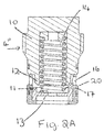
- valve 8 of the present disclosure comprises a preferably cylindrical housing 4" comprising an axially extending end cap 10 and a guide base 11.
- the open end 12 of the end cap 10 is tapered to form a conical shape.
- a sliding spool 13 is mounted in the guide base 11 and the spool 13 and the guide base 11 are arranged to be axially moveable relative to the end cap 10.
- the guide base 11 and spool 13 are biased in an open (downward in the drawings) position by means of a biasing member which is preferably a spring 14.
- the sliding spool 13 is provided with an inlet orifice or so-called control orifice 15 (see Fig. 4 ) in communication with a fluid supply (not shown) on one side and with a fluid flow path through the housing indicated by the arrows in Figs. 2A and 2B .
- the fluid flow path comprises the inlet orifice 15 and an outlet orifice 16 defined in the circumferential wall of the housing, the inlet orifice and the outlet orifice connected via a fluid flow path through a gap 17 defined between the end 12 of the end cap 10 and the guide base 11 in the open position as shown in Fig. 2A .
- the pressure differential is such as to cause the spring 14 to contract.
- the spool 13 and base 11 slide axially towards the end 12 of the end cap 10 (i.e. upwards in the drawings) until the guide base abuts against the end 12 of the end cap shown in Fig. 2B . This then cuts off the flow path between the inlet orifice and the outlet orifice, preventing fluid flow out of the valve.
- the spring 14 is able to expand again, moving the sliding spool 13 and guide base 11 away from the end 12 of the end cap thus opening the fluid path between the inlet orifice and the outlet orifice again.
- Figure 5 shows the above described components in an exploded view, also showing preferred seals 20 and a spring seat 22.
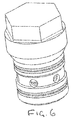
- Fig. 6 shows the valve in perspective view.
- valve 8 of the present disclosure works, essentially, as a poppet valve.
- the inlet orifice 15 generates a pressure differential. This creates a force acting against the biasing member or spring 14, causing the spool 13 to slide to meet the end cap 10.
- the circumferential edge of the spool seats against the end cap, preferably against a tapered end of the end cap, therefore cutting off the fluid flow.
- the excess pressure causes the spool 13 to move to block off the fluid flow path or close the path.
- the spool has to travel less distance to cut off fluid flow than in the prior art arrangement and this smaller travel together with the possible smaller spool mass results in the valve being more quickly responsive to pressure changes.
- the distance the spool has to travel can be less than the diameter of the outlet orifice 16.
- valve of the present disclosure also requires fewer and smaller parts which allows the assembly to be manufactured at lower cost.
- the assembly is also lighter and more compact.
- the present arrangement requires only two orifices, rather than three, to define the fluid flow path which means that there is less general pressure drop in the valve when the valve is fully open.
- the poppet valve closing arrangement of the present disclosure also ensures that there is no leakage when the valve is closed, particularly when the end of the end cap is tapered or conical and the edge of the spool seats against this tapered form.
Landscapes
- Engineering & Computer Science (AREA)
- General Engineering & Computer Science (AREA)
- Mechanical Engineering (AREA)
- Physics & Mathematics (AREA)
- Fluid Mechanics (AREA)
- Safety Valves (AREA)
Abstract
Description
- The present disclosure relates generally to hydraulic valves and more particularly to a valve assembly for limiting fluid flow through the assembly.
- Use of valve assemblies and flow control valves for controlling fluid flow from, e.g., power-assist pumps, is well known. The valve assembly provides for uniform flow of hydraulic fluid from the power-assist pump to, for example, an actuator or other fluid operated device.
- Generally, a flow control valve comprises a housing having a bore therein forming a flow path between an inlet and an outlet port, with a slidably disposed sleeve or other member arranged to occlude the outlet port when fluid flow is to be prevented. This slidable member or sleeve is, conventionally, biased by means of a spring or the like.
- In various known arrangements, the spring is arranged to ensure that, in the normal state, the flow path to the outlet port is open such that a fluid can flow to the inlet port, through the bore and out of the outlet port to control the actuator or the like. If, however, the fluid flow rate exceeds a desired rate, a pressure differential is created in the valve assembly to cause the sliding member to move against the force of the spring so as to occlude the outlet port or to otherwise cause relative movement in relation to the bore so that there is a non-alignment in the fluid flow path from the inlet through the bore to the outlet, thus preventing the flow of fluid through the valve assembly.
- There are many applications of hydraulic power where there is a need to regulate the maximum rate of fluid flow. In aircraft applications, for example, the industry has specific safety regulations concerning the maximum flow rate.
- Whilst, as mentioned above, hydraulic valves find many applications in a wide range of industries, the control valve in the present disclosure will be described, by way of example and not limitation, in relation to the use of hydraulic actuation systems in aircraft.
- Many moving parts in aircraft are controlled using hydraulics. In view of the very high safety requirements in aircraft, such hydraulic systems include a maximum flow requirement. The flow limiter of the present disclosure can be used in any hydraulic system as a flow control valve, wherever there is a requirement for limiting a flow rate.
- The specific examples described below relate to the use of a flow control valve in a thrust reverser hydraulic system but this is purely by way of example.
-
Figs. 1A and1B , described again below, show, in cross-section, a conventional flow limiter valve such as might be used in a thrust reverser actuation system. - The flow limiter valve shown in
Figs. 1A and1B comprises a housing 4 containing aspool 5 arranged on a guide 6 such as to be axially moveable within the housing. - Fluid flows through the flow limiter valve by entering the valve at the
input orifice 1, passing through a bore in the sliding spool and exiting at output orifice 3 in the circumferential wall of the housing, via anoutlet 2 in the spool. - The
sliding spool 5 is biased, by means of aspring 7 such that, under normal flow conditions, thespool outlet 2 is aligned with the output orifice 3 in the wall of the housing. Thus, a flow conduit or path for the fluid is provided frominput orifice 1, via the bore andoutlet 2 through output orifice 3. - Should the fluid flow exceed a given flow rate or pressure, this creates a pressure differential across the input orifice such as to overcome the spring bias, causing compression of the spring such that the sliding spool moves axially moving the spool outlet out of alignment with the outlet orifice 3. This thus closes off the flow path through the valve.
Fig. 1A shows the spool outlet in alignment with the outlet orifice creating a flow path.Fig. 1B shows the slide spool orifice moved out of alignment with the outlet orifice thus closing the fluid flow path. - As can be seen by comparing
Figs. 1A and1B , to stop flow through the valve assembly, the sliding spool needs to move a distance X (Fig. 1 B) . This fairly large distance of movement against the force of the spring means that the flow limiting valve responds slower than is desirable to an excessive pressure difference and flow rate. The mass of the sliding spool also needs to be fairly large to move the distance X. This mass results in some lack of stability causing transient spikes in flow rate. - Also, a shorter spool distance results in lower viscous friction force as well as dry friction force.
- The aim of the present disclosure is to provide a flow limiter valve that responds more quickly to the flow rate and, hence, pressure differential, exceeding a given value, and in a more stable manner.
- The present disclosure provides a flow limiter valve assembly comprising a housing defined by an end cap and a guide base, a fluid inlet orifice provided in the base and a fluid outlet orifice in the circumferential wall of the housing, with a fluid flow path defined from the inlet orifice to the outlet orifice; the valve assembly further comprising a spool mounted in the base of the housing and arranged to be axially moveable relative to the housing end cap; the assembly further comprising biasing means to bias the spool away from the end cap; the assembly being such that when the biasing means biases the spool away from the end cap, the fluid flow path is defined by a gap between the end cap and the spool such that fluid can flow from the inlet orifice through this gap to the outlet orifice, and wherein the biasing means and spool are arranged and configured such that when a pressure differential greater than a predetermined pressure differential is created across the inlet orifice, the spool is caused to move axially against the force of the spring until the spool abuts against the end cap thus closing the gap and, thereby, closing the flow path between the inlet orifice and the outlet orifice.
- The biasing means is preferably a spring.
- The end cap preferably extends axially in a direction of the housing towards the base terminating in a tapered point against which the spool abuts when the spring is compressed by the pressure differential exceeding the predetermined pressure differential value.
- The housing is preferably cylindrical.
- The invention may also reside in a method of limiting fluid flow by causing a spool to move axially relative to an opposing surface such that in response to fluid flow rate exceeding a given value the spool abuts against the opposing surface to prevent fluid flow between the spool and the surface.
-
-
Figs. 1A and1B show a conventional flow limiter valve in the open (Fig. 1A ) and closed (Fig. 1 B) positions. -
Figs. 2A and2B show a cross-sectional view of the flow limiter valve according to this disclosure in the open (Fig. 2A ) and closed (Fig. 2B ) positions. -
Figs. 3A and 3B show the lower part ofFigs. 2A and2B , respectively, in magnified form. -
Fig. 4 shows a sectional view of a flow limiter valve according to the invention. -
Fig. 5 shows an exploded view of a flow limiter valve according to the invention. -
Fig. 6 shows a perspective outside view of the flow limiter valve of this disclosure. - With specific reference, in particular, to
Figs. 2 to 4 , it can be seen that the valve 8 of the present disclosure comprises a preferably cylindrical housing 4" comprising an axially extendingend cap 10 and aguide base 11. - In the preferred embodiment, the
open end 12 of theend cap 10 is tapered to form a conical shape. Asliding spool 13 is mounted in theguide base 11 and thespool 13 and theguide base 11 are arranged to be axially moveable relative to theend cap 10. - The
guide base 11 andspool 13 are biased in an open (downward in the drawings) position by means of a biasing member which is preferably aspring 14. - The
sliding spool 13 is provided with an inlet orifice or so-called control orifice 15 (seeFig. 4 ) in communication with a fluid supply (not shown) on one side and with a fluid flow path through the housing indicated by the arrows inFigs. 2A and2B . - The
control orifice 15 is a typical orifice in a thin wall that generates a pressure differential. It is a typical hydraulic feature and is commonly used to sense a flow. Any change in flow generates a certain pressure differential. This is described by following equation:
- Q - flow rate
- AO - inlet orifice cross section area
- Cd - discharge coefficient
- Δp - pressure differential
- ρ - fluid density
- The fluid flow path comprises the
inlet orifice 15 and anoutlet orifice 16 defined in the circumferential wall of the housing, the inlet orifice and the outlet orifice connected via a fluid flow path through agap 17 defined between theend 12 of theend cap 10 and theguide base 11 in the open position as shown inFig. 2A . When the rate of fluid flowing into the valve 8 increases, this creates a pressure differential at the inlet orcontrol orifice 15. When the fluid rate increases beyond a predetermined threshold value, the pressure differential is such as to cause thespring 14 to contract. Thespool 13 andbase 11 slide axially towards theend 12 of the end cap 10 (i.e. upwards in the drawings) until the guide base abuts against theend 12 of the end cap shown inFig. 2B . This then cuts off the flow path between the inlet orifice and the outlet orifice, preventing fluid flow out of the valve. - As the pressure differential is removed due to a decrease in flow rate, the
spring 14 is able to expand again, moving the slidingspool 13 and guidebase 11 away from theend 12 of the end cap thus opening the fluid path between the inlet orifice and the outlet orifice again. -
Figure 5 shows the above described components in an exploded view, also showingpreferred seals 20 and aspring seat 22. -
Fig. 6 shows the valve in perspective view. - During closing, the valve 8 of the present disclosure works, essentially, as a poppet valve. The
inlet orifice 15 generates a pressure differential. This creates a force acting against the biasing member orspring 14, causing thespool 13 to slide to meet theend cap 10. The circumferential edge of the spool seats against the end cap, preferably against a tapered end of the end cap, therefore cutting off the fluid flow. - The flow limiter valve 8 operates according to the following force equilibrium equation:

- AS -cross section area of sliding spool
- Psp - spring force
- Δp - pressure differential across inlet orifice
- Thus, in contrast to the existing systems wherein the excess pressure from the excessive fluid flow rate causes the slider to move the components of the fluid flow path out of alignment, in the present invention, the excess pressure causes the
spool 13 to move to block off the fluid flow path or close the path. - With the valve of the present disclosure, the spool has to travel less distance to cut off fluid flow than in the prior art arrangement and this smaller travel together with the possible smaller spool mass results in the valve being more quickly responsive to pressure changes. The distance the spool has to travel can be less than the diameter of the
outlet orifice 16. - The valve of the present disclosure also requires fewer and smaller parts which allows the assembly to be manufactured at lower cost. The assembly is also lighter and more compact.
- As compared to the prior art arrangement, the present arrangement requires only two orifices, rather than three, to define the fluid flow path which means that there is less general pressure drop in the valve when the valve is fully open.
- The poppet valve closing arrangement of the present disclosure also ensures that there is no leakage when the valve is closed, particularly when the end of the end cap is tapered or conical and the edge of the spool seats against this tapered form.
Claims (11)
- A flow limiter valve comprising a housing (4") defined by an end cap (10) and a guide base (11);
an outlet orifice (16) in a wall (20) of the housing (4");
a spool (13) having an inlet orifice (15) and being mounted in the guide base (11) of the housing and arranged to be axially moveable relative to the housing end cap (10);
biasing means (14) configured to bias the spool away from the end cap;
a fluid flow path being defined from the inlet orifice (15), through a gap (17) between the end cap and the spool and out the outlet orifice, and wherein the biasing means and spool are arranged and configured such that when a pressure differential greater than a selected pressure differential is created across the inlet orifice, the spool is caused to move to decrease the gap (17) and, thereby, decreasing fluid flow through the flow path. - The flow limiter valve of claim 1, wherein the biasing means (14) comprises a spring.
- The flow limiter valve of claim 1 or 2, wherein the end cap (10) extends axially in a direction of the housing towards the base terminating in a tapered point (12).
- The flow limiter valve of claim 3, wherein the gap is defined between the tapered point (12) and a corner of the spool (13).
- The flow limiter valve of claim 4, wherein the tapered point (12) defines a conical surface of the end cap and the spool (13) defines a surface at 90° to the tapered point (12) such that the gap is defined by the conical surface and the spool surface.
- The flow limiter valve of any of claims 1 to 5, wherein the spool (13) abuts against the end cap (10) when the pressure differential exceeds a second selected pressure differential valve, thus preventing fluid flow.
- The flow limiter valve of any preceding claim, wherein the housing (4") is cylindrical.
- The flow limiter valve of claim 7, wherein the wall (20) is a circumferential wall.
- A method of limiting fluid flow comprising:moving a spool relative to a surface in response to fluid flow rate through the spool exceeding a selected value; anddecreasing a gap defined between the spool and the surface to reduce fluid flow rate between the spool and the surface.
- The method of claim 9 using the flow limiter valve of any of claims 1 to 4.
- The method of claim 9 or 10, wherein the spool is moved axially.
Priority Applications (2)
| Application Number | Priority Date | Filing Date | Title |
|---|---|---|---|
| EP16160123.2A EP3220026B1 (en) | 2016-03-14 | 2016-03-14 | Flow limiter valve |
| US15/404,391 US10731771B2 (en) | 2016-03-14 | 2017-01-12 | Flow limiter valve |
Applications Claiming Priority (1)
| Application Number | Priority Date | Filing Date | Title |
|---|---|---|---|
| EP16160123.2A EP3220026B1 (en) | 2016-03-14 | 2016-03-14 | Flow limiter valve |
Publications (2)
| Publication Number | Publication Date |
|---|---|
| EP3220026A1 true EP3220026A1 (en) | 2017-09-20 |
| EP3220026B1 EP3220026B1 (en) | 2019-08-21 |
Family
ID=55588072
Family Applications (1)
| Application Number | Title | Priority Date | Filing Date |
|---|---|---|---|
| EP16160123.2A Active EP3220026B1 (en) | 2016-03-14 | 2016-03-14 | Flow limiter valve |
Country Status (2)
| Country | Link |
|---|---|
| US (1) | US10731771B2 (en) |
| EP (1) | EP3220026B1 (en) |
Families Citing this family (7)
| Publication number | Priority date | Publication date | Assignee | Title |
|---|---|---|---|---|
| DE102019204510A1 (en) * | 2019-03-29 | 2020-10-01 | Zf Friedrichshafen Ag | Hydraulic control device for an automatic transmission of a motor vehicle |
| US11913586B2 (en) | 2020-08-11 | 2024-02-27 | The Boeing Company | Multi-function orifice subassembly for flow limiters |
| CN113883116B (en) * | 2021-09-29 | 2025-07-18 | 三一汽车制造有限公司 | Oil drain valve, energy storage device, hydraulic system and working machine |
| CN114087407B (en) * | 2021-11-18 | 2024-10-29 | 新乡航空工业(集团)有限公司 | Flow regulating device |
| USD1016989S1 (en) | 2023-05-11 | 2024-03-05 | Fairview Ltd. | Multi-directional vent limiter |
| CN118998411A (en) * | 2023-05-22 | 2024-11-22 | 浙江三花智能控制股份有限公司 | Valve device |
| CN116538329B (en) * | 2023-06-20 | 2026-03-27 | 宁波方太厨具有限公司 | Flow stabilizer and water heater |
Citations (6)
| Publication number | Priority date | Publication date | Assignee | Title |
|---|---|---|---|---|
| JPS60121371A (en) * | 1983-12-01 | 1985-06-28 | Sanyo Electric Co Ltd | Flow-rate regulator |
| US5215178A (en) * | 1991-03-25 | 1993-06-01 | Mcneilus Truck And Manufacturing, Inc. | Safety valve for discharge chutes on cement mixer |
| US20080006330A1 (en) * | 2006-07-05 | 2008-01-10 | Zhou Huasong | A Throttle Mechanism |
| WO2008019863A1 (en) * | 2006-08-17 | 2008-02-21 | Trw Automative Gmbh | Hydraulic valve and hydraulic circuit having a hydraulic valve of said type |
| US20100101666A1 (en) * | 2008-10-28 | 2010-04-29 | Gm Global Technology Operations, Inc. | Pressure regulator for hydrogen storage system |
| US20150330474A1 (en) * | 2014-05-16 | 2015-11-19 | Rausch & Pausch Gmbh | Hydraulic system |
Family Cites Families (11)
| Publication number | Priority date | Publication date | Assignee | Title |
|---|---|---|---|---|
| US2093015A (en) * | 1935-10-11 | 1937-09-14 | Joseph D Madden | Hydraulic brake |
| US2960109A (en) * | 1957-01-07 | 1960-11-15 | Gen Controls Co | Flow regulator |
| US2984261A (en) * | 1958-04-16 | 1961-05-16 | W A Kates Company | Fluid flow regulator |
| US4347867A (en) * | 1980-12-29 | 1982-09-07 | W-K-M Wellhead Systems, Inc. | Safety valve |
| US4785847A (en) * | 1987-03-27 | 1988-11-22 | Allied-Signal Inc. | Unitary poppet valve assembly for a proportioning valve |
| US4867198A (en) * | 1988-10-11 | 1989-09-19 | Faust Bobby G | Adjustable flow regulating valve |
| US4951478A (en) * | 1989-10-24 | 1990-08-28 | Chrysler Corporation | Variable capacity control valve |
| US5400694A (en) * | 1994-03-04 | 1995-03-28 | Mcneilus Truck And Manufacturing, Inc. | Hydraulic cylinder with internal safety valve |
| US5462081A (en) * | 1994-08-24 | 1995-10-31 | Nupro Company | Excess flow valve |
| US7111638B2 (en) * | 2003-05-06 | 2006-09-26 | Safety Flow Company, Llc | Excess flow shutoff |
| US7434595B2 (en) * | 2004-08-30 | 2008-10-14 | Watts Water Technologies, Inc. | Safety valve assembly having set and reset mechanisms |
-
2016
- 2016-03-14 EP EP16160123.2A patent/EP3220026B1/en active Active
-
2017
- 2017-01-12 US US15/404,391 patent/US10731771B2/en not_active Expired - Fee Related
Patent Citations (6)
| Publication number | Priority date | Publication date | Assignee | Title |
|---|---|---|---|---|
| JPS60121371A (en) * | 1983-12-01 | 1985-06-28 | Sanyo Electric Co Ltd | Flow-rate regulator |
| US5215178A (en) * | 1991-03-25 | 1993-06-01 | Mcneilus Truck And Manufacturing, Inc. | Safety valve for discharge chutes on cement mixer |
| US20080006330A1 (en) * | 2006-07-05 | 2008-01-10 | Zhou Huasong | A Throttle Mechanism |
| WO2008019863A1 (en) * | 2006-08-17 | 2008-02-21 | Trw Automative Gmbh | Hydraulic valve and hydraulic circuit having a hydraulic valve of said type |
| US20100101666A1 (en) * | 2008-10-28 | 2010-04-29 | Gm Global Technology Operations, Inc. | Pressure regulator for hydrogen storage system |
| US20150330474A1 (en) * | 2014-05-16 | 2015-11-19 | Rausch & Pausch Gmbh | Hydraulic system |
Also Published As
| Publication number | Publication date |
|---|---|
| US20170261118A1 (en) | 2017-09-14 |
| EP3220026B1 (en) | 2019-08-21 |
| US10731771B2 (en) | 2020-08-04 |
Similar Documents
| Publication | Publication Date | Title |
|---|---|---|
| EP3220026B1 (en) | Flow limiter valve | |
| EP0698759B1 (en) | Excess flow valve | |
| CN101490456B (en) | Two-way force feedback poppet valve | |
| US8256739B2 (en) | Poppet valve operated by an electrohydraulic poppet pilot valve | |
| US6966329B2 (en) | Proportional pilot-operated flow control valve | |
| EP1001197B1 (en) | Pilot operated pressure valve | |
| EP2348376B1 (en) | Flow control valve with damping chamber | |
| US7069945B2 (en) | Cartridge relief valve with improved stability | |
| US20100139795A1 (en) | Direct-acting pilot pressure control solenoid | |
| US20150276088A1 (en) | Pressure regulating valve and method of adjusting damping of the same | |
| JP7304423B2 (en) | Pressure regulating valves for controlling or regulating the pressure of pressurized fluid in pilot pressure chambers and devices comprising such pressure regulating valves | |
| US4699166A (en) | Hydraulic fuse valve assembly | |
| WO1984001010A1 (en) | Hydraulic fuse valve assembly | |
| WO2015149906A1 (en) | Proportional pressure control valve | |
| US20070290152A1 (en) | Poppet valve | |
| WO2015157157A1 (en) | Servo valve | |
| US5232013A (en) | Check valve with poppet damping mechanism | |
| EP2792889A1 (en) | Flow regulating valve assembly | |
| EP2944852B1 (en) | Contamination resistant cartridge valve | |
| EP3599398A1 (en) | Damping mechanism for valves | |
| US4345736A (en) | Solenoid operated valve and dashpot assembly | |
| EP2821683B1 (en) | Pressure regulating valve | |
| US3155111A (en) | Temperature compensated flow control vavle | |
| US3478777A (en) | Valve | |
| US4471940A (en) | Dashpot assembly |
Legal Events
| Date | Code | Title | Description |
|---|---|---|---|
| PUAI | Public reference made under article 153(3) epc to a published international application that has entered the european phase |
Free format text: ORIGINAL CODE: 0009012 |
|
| STAA | Information on the status of an ep patent application or granted ep patent |
Free format text: STATUS: THE APPLICATION HAS BEEN PUBLISHED |
|
| AK | Designated contracting states |
Kind code of ref document: A1 Designated state(s): AL AT BE BG CH CY CZ DE DK EE ES FI FR GB GR HR HU IE IS IT LI LT LU LV MC MK MT NL NO PL PT RO RS SE SI SK SM TR |
|
| AX | Request for extension of the european patent |
Extension state: BA ME |
|
| STAA | Information on the status of an ep patent application or granted ep patent |
Free format text: STATUS: REQUEST FOR EXAMINATION WAS MADE |
|
| 17P | Request for examination filed |
Effective date: 20180320 |
|
| RBV | Designated contracting states (corrected) |
Designated state(s): AL AT BE BG CH CY CZ DE DK EE ES FI FR GB GR HR HU IE IS IT LI LT LU LV MC MK MT NL NO PL PT RO RS SE SI SK SM TR |
|
| STAA | Information on the status of an ep patent application or granted ep patent |
Free format text: STATUS: EXAMINATION IS IN PROGRESS |
|
| 17Q | First examination report despatched |
Effective date: 20180613 |
|
| GRAP | Despatch of communication of intention to grant a patent |
Free format text: ORIGINAL CODE: EPIDOSNIGR1 |
|
| STAA | Information on the status of an ep patent application or granted ep patent |
Free format text: STATUS: GRANT OF PATENT IS INTENDED |
|
| INTG | Intention to grant announced |
Effective date: 20181102 |
|
| GRAS | Grant fee paid |
Free format text: ORIGINAL CODE: EPIDOSNIGR3 |
|
| GRAA | (expected) grant |
Free format text: ORIGINAL CODE: 0009210 |
|
| STAA | Information on the status of an ep patent application or granted ep patent |
Free format text: STATUS: THE PATENT HAS BEEN GRANTED |
|
| AK | Designated contracting states |
Kind code of ref document: B1 Designated state(s): AL AT BE BG CH CY CZ DE DK EE ES FI FR GB GR HR HU IE IS IT LI LT LU LV MC MK MT NL NO PL PT RO RS SE SI SK SM TR |
|
| REG | Reference to a national code |
Ref country code: GB Ref legal event code: FG4D |
|
| REG | Reference to a national code |
Ref country code: CH Ref legal event code: EP |
|
| REG | Reference to a national code |
Ref country code: DE Ref legal event code: R096 Ref document number: 602016018840 Country of ref document: DE |
|
| REG | Reference to a national code |
Ref country code: AT Ref legal event code: REF Ref document number: 1170149 Country of ref document: AT Kind code of ref document: T Effective date: 20190915 |
|
| REG | Reference to a national code |
Ref country code: IE Ref legal event code: FG4D |
|
| REG | Reference to a national code |
Ref country code: LT Ref legal event code: MG4D |
|
| REG | Reference to a national code |
Ref country code: NL Ref legal event code: MP Effective date: 20190821 |
|
| PG25 | Lapsed in a contracting state [announced via postgrant information from national office to epo] |
Ref country code: NL Free format text: LAPSE BECAUSE OF FAILURE TO SUBMIT A TRANSLATION OF THE DESCRIPTION OR TO PAY THE FEE WITHIN THE PRESCRIBED TIME-LIMIT Effective date: 20190821 Ref country code: BG Free format text: LAPSE BECAUSE OF FAILURE TO SUBMIT A TRANSLATION OF THE DESCRIPTION OR TO PAY THE FEE WITHIN THE PRESCRIBED TIME-LIMIT Effective date: 20191121 Ref country code: SE Free format text: LAPSE BECAUSE OF FAILURE TO SUBMIT A TRANSLATION OF THE DESCRIPTION OR TO PAY THE FEE WITHIN THE PRESCRIBED TIME-LIMIT Effective date: 20190821 Ref country code: NO Free format text: LAPSE BECAUSE OF FAILURE TO SUBMIT A TRANSLATION OF THE DESCRIPTION OR TO PAY THE FEE WITHIN THE PRESCRIBED TIME-LIMIT Effective date: 20191121 Ref country code: LT Free format text: LAPSE BECAUSE OF FAILURE TO SUBMIT A TRANSLATION OF THE DESCRIPTION OR TO PAY THE FEE WITHIN THE PRESCRIBED TIME-LIMIT Effective date: 20190821 Ref country code: PT Free format text: LAPSE BECAUSE OF FAILURE TO SUBMIT A TRANSLATION OF THE DESCRIPTION OR TO PAY THE FEE WITHIN THE PRESCRIBED TIME-LIMIT Effective date: 20191223 Ref country code: HR Free format text: LAPSE BECAUSE OF FAILURE TO SUBMIT A TRANSLATION OF THE DESCRIPTION OR TO PAY THE FEE WITHIN THE PRESCRIBED TIME-LIMIT Effective date: 20190821 Ref country code: FI Free format text: LAPSE BECAUSE OF FAILURE TO SUBMIT A TRANSLATION OF THE DESCRIPTION OR TO PAY THE FEE WITHIN THE PRESCRIBED TIME-LIMIT Effective date: 20190821 |
|
| PG25 | Lapsed in a contracting state [announced via postgrant information from national office to epo] |
Ref country code: LV Free format text: LAPSE BECAUSE OF FAILURE TO SUBMIT A TRANSLATION OF THE DESCRIPTION OR TO PAY THE FEE WITHIN THE PRESCRIBED TIME-LIMIT Effective date: 20190821 Ref country code: ES Free format text: LAPSE BECAUSE OF FAILURE TO SUBMIT A TRANSLATION OF THE DESCRIPTION OR TO PAY THE FEE WITHIN THE PRESCRIBED TIME-LIMIT Effective date: 20190821 Ref country code: AL Free format text: LAPSE BECAUSE OF FAILURE TO SUBMIT A TRANSLATION OF THE DESCRIPTION OR TO PAY THE FEE WITHIN THE PRESCRIBED TIME-LIMIT Effective date: 20190821 Ref country code: GR Free format text: LAPSE BECAUSE OF FAILURE TO SUBMIT A TRANSLATION OF THE DESCRIPTION OR TO PAY THE FEE WITHIN THE PRESCRIBED TIME-LIMIT Effective date: 20191122 Ref country code: RS Free format text: LAPSE BECAUSE OF FAILURE TO SUBMIT A TRANSLATION OF THE DESCRIPTION OR TO PAY THE FEE WITHIN THE PRESCRIBED TIME-LIMIT Effective date: 20190821 Ref country code: IS Free format text: LAPSE BECAUSE OF FAILURE TO SUBMIT A TRANSLATION OF THE DESCRIPTION OR TO PAY THE FEE WITHIN THE PRESCRIBED TIME-LIMIT Effective date: 20191221 |
|
| REG | Reference to a national code |
Ref country code: AT Ref legal event code: MK05 Ref document number: 1170149 Country of ref document: AT Kind code of ref document: T Effective date: 20190821 |
|
| PG25 | Lapsed in a contracting state [announced via postgrant information from national office to epo] |
Ref country code: TR Free format text: LAPSE BECAUSE OF FAILURE TO SUBMIT A TRANSLATION OF THE DESCRIPTION OR TO PAY THE FEE WITHIN THE PRESCRIBED TIME-LIMIT Effective date: 20190821 |
|
| PG25 | Lapsed in a contracting state [announced via postgrant information from national office to epo] |
Ref country code: AT Free format text: LAPSE BECAUSE OF FAILURE TO SUBMIT A TRANSLATION OF THE DESCRIPTION OR TO PAY THE FEE WITHIN THE PRESCRIBED TIME-LIMIT Effective date: 20190821 Ref country code: PL Free format text: LAPSE BECAUSE OF FAILURE TO SUBMIT A TRANSLATION OF THE DESCRIPTION OR TO PAY THE FEE WITHIN THE PRESCRIBED TIME-LIMIT Effective date: 20190821 Ref country code: RO Free format text: LAPSE BECAUSE OF FAILURE TO SUBMIT A TRANSLATION OF THE DESCRIPTION OR TO PAY THE FEE WITHIN THE PRESCRIBED TIME-LIMIT Effective date: 20190821 Ref country code: IT Free format text: LAPSE BECAUSE OF FAILURE TO SUBMIT A TRANSLATION OF THE DESCRIPTION OR TO PAY THE FEE WITHIN THE PRESCRIBED TIME-LIMIT Effective date: 20190821 Ref country code: EE Free format text: LAPSE BECAUSE OF FAILURE TO SUBMIT A TRANSLATION OF THE DESCRIPTION OR TO PAY THE FEE WITHIN THE PRESCRIBED TIME-LIMIT Effective date: 20190821 Ref country code: DK Free format text: LAPSE BECAUSE OF FAILURE TO SUBMIT A TRANSLATION OF THE DESCRIPTION OR TO PAY THE FEE WITHIN THE PRESCRIBED TIME-LIMIT Effective date: 20190821 |
|
| PG25 | Lapsed in a contracting state [announced via postgrant information from national office to epo] |
Ref country code: SM Free format text: LAPSE BECAUSE OF FAILURE TO SUBMIT A TRANSLATION OF THE DESCRIPTION OR TO PAY THE FEE WITHIN THE PRESCRIBED TIME-LIMIT Effective date: 20190821 Ref country code: CZ Free format text: LAPSE BECAUSE OF FAILURE TO SUBMIT A TRANSLATION OF THE DESCRIPTION OR TO PAY THE FEE WITHIN THE PRESCRIBED TIME-LIMIT Effective date: 20190821 Ref country code: SK Free format text: LAPSE BECAUSE OF FAILURE TO SUBMIT A TRANSLATION OF THE DESCRIPTION OR TO PAY THE FEE WITHIN THE PRESCRIBED TIME-LIMIT Effective date: 20190821 Ref country code: IS Free format text: LAPSE BECAUSE OF FAILURE TO SUBMIT A TRANSLATION OF THE DESCRIPTION OR TO PAY THE FEE WITHIN THE PRESCRIBED TIME-LIMIT Effective date: 20200224 |
|
| REG | Reference to a national code |
Ref country code: DE Ref legal event code: R097 Ref document number: 602016018840 Country of ref document: DE |
|
| PLBE | No opposition filed within time limit |
Free format text: ORIGINAL CODE: 0009261 |
|
| STAA | Information on the status of an ep patent application or granted ep patent |
Free format text: STATUS: NO OPPOSITION FILED WITHIN TIME LIMIT |
|
| PG2D | Information on lapse in contracting state deleted |
Ref country code: IS |
|
| 26N | No opposition filed |
Effective date: 20200603 |
|
| PG25 | Lapsed in a contracting state [announced via postgrant information from national office to epo] |
Ref country code: SI Free format text: LAPSE BECAUSE OF FAILURE TO SUBMIT A TRANSLATION OF THE DESCRIPTION OR TO PAY THE FEE WITHIN THE PRESCRIBED TIME-LIMIT Effective date: 20190821 |
|
| PG25 | Lapsed in a contracting state [announced via postgrant information from national office to epo] |
Ref country code: MC Free format text: LAPSE BECAUSE OF FAILURE TO SUBMIT A TRANSLATION OF THE DESCRIPTION OR TO PAY THE FEE WITHIN THE PRESCRIBED TIME-LIMIT Effective date: 20190821 |
|
| REG | Reference to a national code |
Ref country code: CH Ref legal event code: PL |
|
| REG | Reference to a national code |
Ref country code: BE Ref legal event code: MM Effective date: 20200331 |
|
| PG25 | Lapsed in a contracting state [announced via postgrant information from national office to epo] |
Ref country code: LU Free format text: LAPSE BECAUSE OF NON-PAYMENT OF DUE FEES Effective date: 20200314 |
|
| PG25 | Lapsed in a contracting state [announced via postgrant information from national office to epo] |
Ref country code: CH Free format text: LAPSE BECAUSE OF NON-PAYMENT OF DUE FEES Effective date: 20200331 Ref country code: IE Free format text: LAPSE BECAUSE OF NON-PAYMENT OF DUE FEES Effective date: 20200314 Ref country code: LI Free format text: LAPSE BECAUSE OF NON-PAYMENT OF DUE FEES Effective date: 20200331 |
|
| PG25 | Lapsed in a contracting state [announced via postgrant information from national office to epo] |
Ref country code: BE Free format text: LAPSE BECAUSE OF NON-PAYMENT OF DUE FEES Effective date: 20200331 |
|
| PG25 | Lapsed in a contracting state [announced via postgrant information from national office to epo] |
Ref country code: MT Free format text: LAPSE BECAUSE OF FAILURE TO SUBMIT A TRANSLATION OF THE DESCRIPTION OR TO PAY THE FEE WITHIN THE PRESCRIBED TIME-LIMIT Effective date: 20190821 Ref country code: CY Free format text: LAPSE BECAUSE OF FAILURE TO SUBMIT A TRANSLATION OF THE DESCRIPTION OR TO PAY THE FEE WITHIN THE PRESCRIBED TIME-LIMIT Effective date: 20190821 |
|
| PG25 | Lapsed in a contracting state [announced via postgrant information from national office to epo] |
Ref country code: MK Free format text: LAPSE BECAUSE OF FAILURE TO SUBMIT A TRANSLATION OF THE DESCRIPTION OR TO PAY THE FEE WITHIN THE PRESCRIBED TIME-LIMIT Effective date: 20190821 |
|
| PGFP | Annual fee paid to national office [announced via postgrant information from national office to epo] |
Ref country code: FR Payment date: 20230222 Year of fee payment: 8 |
|
| PGFP | Annual fee paid to national office [announced via postgrant information from national office to epo] |
Ref country code: GB Payment date: 20230222 Year of fee payment: 8 Ref country code: DE Payment date: 20230221 Year of fee payment: 8 |
|
| P01 | Opt-out of the competence of the unified patent court (upc) registered |
Effective date: 20230522 |
|
| REG | Reference to a national code |
Ref country code: DE Ref legal event code: R119 Ref document number: 602016018840 Country of ref document: DE |
|
| GBPC | Gb: european patent ceased through non-payment of renewal fee |
Effective date: 20240314 |
|
| PG25 | Lapsed in a contracting state [announced via postgrant information from national office to epo] |
Ref country code: DE Free format text: LAPSE BECAUSE OF NON-PAYMENT OF DUE FEES Effective date: 20241001 |
|
| PG25 | Lapsed in a contracting state [announced via postgrant information from national office to epo] |
Ref country code: GB Free format text: LAPSE BECAUSE OF NON-PAYMENT OF DUE FEES Effective date: 20240314 |
|
| PG25 | Lapsed in a contracting state [announced via postgrant information from national office to epo] |
Ref country code: FR Free format text: LAPSE BECAUSE OF NON-PAYMENT OF DUE FEES Effective date: 20240331 |
|
| PG25 | Lapsed in a contracting state [announced via postgrant information from national office to epo] |
Ref country code: GB Free format text: LAPSE BECAUSE OF NON-PAYMENT OF DUE FEES Effective date: 20240314 Ref country code: FR Free format text: LAPSE BECAUSE OF NON-PAYMENT OF DUE FEES Effective date: 20240331 Ref country code: DE Free format text: LAPSE BECAUSE OF NON-PAYMENT OF DUE FEES Effective date: 20241001 |