EP3220019A1 - Shaft sealing mechanism - Google Patents
Shaft sealing mechanism Download PDFInfo
- Publication number
- EP3220019A1 EP3220019A1 EP15869958.7A EP15869958A EP3220019A1 EP 3220019 A1 EP3220019 A1 EP 3220019A1 EP 15869958 A EP15869958 A EP 15869958A EP 3220019 A1 EP3220019 A1 EP 3220019A1
- Authority
- EP
- European Patent Office
- Prior art keywords
- pressure
- thin
- rotating shaft
- plate seal
- low
- Prior art date
- Legal status (The legal status is an assumption and is not a legal conclusion. Google has not performed a legal analysis and makes no representation as to the accuracy of the status listed.)
- Granted
Links
Images

Classifications
-
- F—MECHANICAL ENGINEERING; LIGHTING; HEATING; WEAPONS; BLASTING
- F01—MACHINES OR ENGINES IN GENERAL; ENGINE PLANTS IN GENERAL; STEAM ENGINES
- F01D—NON-POSITIVE DISPLACEMENT MACHINES OR ENGINES, e.g. STEAM TURBINES
- F01D11/00—Preventing or minimising internal leakage of working-fluid, e.g. between stages
-
- F—MECHANICAL ENGINEERING; LIGHTING; HEATING; WEAPONS; BLASTING
- F01—MACHINES OR ENGINES IN GENERAL; ENGINE PLANTS IN GENERAL; STEAM ENGINES
- F01D—NON-POSITIVE DISPLACEMENT MACHINES OR ENGINES, e.g. STEAM TURBINES
- F01D11/00—Preventing or minimising internal leakage of working-fluid, e.g. between stages
- F01D11/001—Preventing or minimising internal leakage of working-fluid, e.g. between stages for sealing space between stator blade and rotor
-
- F—MECHANICAL ENGINEERING; LIGHTING; HEATING; WEAPONS; BLASTING
- F02—COMBUSTION ENGINES; HOT-GAS OR COMBUSTION-PRODUCT ENGINE PLANTS
- F02C—GAS-TURBINE PLANTS; AIR INTAKES FOR JET-PROPULSION PLANTS; CONTROLLING FUEL SUPPLY IN AIR-BREATHING JET-PROPULSION PLANTS
- F02C7/00—Features, components parts, details or accessories, not provided for in, or of interest apart form groups F02C1/00 - F02C6/00; Air intakes for jet-propulsion plants
- F02C7/28—Arrangement of seals
-
- F—MECHANICAL ENGINEERING; LIGHTING; HEATING; WEAPONS; BLASTING
- F04—POSITIVE - DISPLACEMENT MACHINES FOR LIQUIDS; PUMPS FOR LIQUIDS OR ELASTIC FLUIDS
- F04D—NON-POSITIVE-DISPLACEMENT PUMPS
- F04D29/00—Details, component parts, or accessories
- F04D29/08—Sealings
- F04D29/10—Shaft sealings
-
- F—MECHANICAL ENGINEERING; LIGHTING; HEATING; WEAPONS; BLASTING
- F16—ENGINEERING ELEMENTS AND UNITS; GENERAL MEASURES FOR PRODUCING AND MAINTAINING EFFECTIVE FUNCTIONING OF MACHINES OR INSTALLATIONS; THERMAL INSULATION IN GENERAL
- F16J—PISTONS; CYLINDERS; SEALINGS
- F16J15/00—Sealings
- F16J15/16—Sealings between relatively-moving surfaces
- F16J15/18—Sealings between relatively-moving surfaces with stuffing-boxes for elastic or plastic packings
- F16J15/20—Packing materials therefor
- F16J15/22—Packing materials therefor shaped as strands, ropes, threads, ribbons, or the like
-
- F—MECHANICAL ENGINEERING; LIGHTING; HEATING; WEAPONS; BLASTING
- F16—ENGINEERING ELEMENTS AND UNITS; GENERAL MEASURES FOR PRODUCING AND MAINTAINING EFFECTIVE FUNCTIONING OF MACHINES OR INSTALLATIONS; THERMAL INSULATION IN GENERAL
- F16J—PISTONS; CYLINDERS; SEALINGS
- F16J15/00—Sealings
- F16J15/16—Sealings between relatively-moving surfaces
- F16J15/32—Sealings between relatively-moving surfaces with elastic sealings, e.g. O-rings
- F16J15/3284—Sealings between relatively-moving surfaces with elastic sealings, e.g. O-rings characterised by their structure; Selection of materials
- F16J15/3292—Lamellar structures
-
- F—MECHANICAL ENGINEERING; LIGHTING; HEATING; WEAPONS; BLASTING
- F01—MACHINES OR ENGINES IN GENERAL; ENGINE PLANTS IN GENERAL; STEAM ENGINES
- F01D—NON-POSITIVE DISPLACEMENT MACHINES OR ENGINES, e.g. STEAM TURBINES
- F01D11/00—Preventing or minimising internal leakage of working-fluid, e.g. between stages
- F01D11/003—Preventing or minimising internal leakage of working-fluid, e.g. between stages by packing rings; Mechanical seals
-
- F—MECHANICAL ENGINEERING; LIGHTING; HEATING; WEAPONS; BLASTING
- F05—INDEXING SCHEMES RELATING TO ENGINES OR PUMPS IN VARIOUS SUBCLASSES OF CLASSES F01-F04
- F05D—INDEXING SCHEME FOR ASPECTS RELATING TO NON-POSITIVE-DISPLACEMENT MACHINES OR ENGINES, GAS-TURBINES OR JET-PROPULSION PLANTS
- F05D2240/00—Components
- F05D2240/55—Seals
-
- F—MECHANICAL ENGINEERING; LIGHTING; HEATING; WEAPONS; BLASTING
- F05—INDEXING SCHEMES RELATING TO ENGINES OR PUMPS IN VARIOUS SUBCLASSES OF CLASSES F01-F04
- F05D—INDEXING SCHEME FOR ASPECTS RELATING TO NON-POSITIVE-DISPLACEMENT MACHINES OR ENGINES, GAS-TURBINES OR JET-PROPULSION PLANTS
- F05D2240/00—Components
- F05D2240/55—Seals
- F05D2240/57—Leaf seals
-
- F—MECHANICAL ENGINEERING; LIGHTING; HEATING; WEAPONS; BLASTING
- F05—INDEXING SCHEMES RELATING TO ENGINES OR PUMPS IN VARIOUS SUBCLASSES OF CLASSES F01-F04
- F05D—INDEXING SCHEME FOR ASPECTS RELATING TO NON-POSITIVE-DISPLACEMENT MACHINES OR ENGINES, GAS-TURBINES OR JET-PROPULSION PLANTS
- F05D2240/00—Components
- F05D2240/55—Seals
- F05D2240/59—Lamellar seals
-
- F—MECHANICAL ENGINEERING; LIGHTING; HEATING; WEAPONS; BLASTING
- F16—ENGINEERING ELEMENTS AND UNITS; GENERAL MEASURES FOR PRODUCING AND MAINTAINING EFFECTIVE FUNCTIONING OF MACHINES OR INSTALLATIONS; THERMAL INSULATION IN GENERAL
- F16J—PISTONS; CYLINDERS; SEALINGS
- F16J15/00—Sealings
- F16J15/16—Sealings between relatively-moving surfaces
- F16J15/18—Sealings between relatively-moving surfaces with stuffing-boxes for elastic or plastic packings
- F16J15/24—Sealings between relatively-moving surfaces with stuffing-boxes for elastic or plastic packings with radially or tangentially compressed packing
Definitions
- Patent Document 1 United States Patent Application Publication No. 20120007318
- the present invention is to solve the above problems and an object thereof is to provide a shaft sealing mechanism capable of reducing vibration of the thin-plate seal pieces by making the pressure of the fluid flowing between each adjacent thin-plate seal pieces uniform to eliminate the difference between the pressures exerted on the upper and the lower surfaces of the thin-plate seal pieces.
- the shaft sealing mechanism 11 has an annular seal structure in which multiple layers of the thin-plate seal pieces 22 are arranged in the circumferential direction of the rotating shaft 13, and in which the boundary formed by a large number of the thin-plate seal pieces 22 arranged annularly partitions the annular space 14 into a high-pressure-side region being an upstream side in the fluid flowing direction and a low-pressure-side region being an downstream side in the fluid flowing direction.
- This structure reduces the amount of leakage of the fluid G leaked from the high-pressure-side region to the low-pressure-side region.
- the pressure distribution of the fluid G on the upper and lower surfaces of the thin-plate seal pieces 22 can be set in accordance with the gap lengths of the high-pressure-side gap ⁇ H and the low-pressure-side gap ⁇ L.
- the magnitude of the pressure difference due to relative positional difference in the pressure distribution between the upper and lower surfaces of the thin-plate seal pieces 22.
Landscapes
- Engineering & Computer Science (AREA)
- General Engineering & Computer Science (AREA)
- Mechanical Engineering (AREA)
- Chemical & Material Sciences (AREA)
- Combustion & Propulsion (AREA)
- Turbine Rotor Nozzle Sealing (AREA)
- Sealing Using Fluids, Sealing Without Contact, And Removal Of Oil (AREA)
- Sealing Devices (AREA)
Abstract
Description
- The present invention relates to a shaft sealing mechanism disposed around a rotating shaft of a steam turbine or a gas turbine for reducing the amount of leakage of fluid leaked from a high-pressure side to a low-pressure side.
- Conventionally, a shaft sealing mechanism for reducing the amount of leakage of fluid leaked from a high-pressure side to a low-pressure side is disposed around a rotating shaft of a steam turbine or a gas turbine, in order to reduce a loss of driving force. Such a shaft sealing mechanism has an annular seal structure in which multiple layers of thin-plate seal pieces in flat plate shapes with their width dimensions being in the rotating shaft direction are arranged in the circumferential direction of the rotating shaft. Outer-circumferential-side proximal ends of the thin-plate seal pieces are fixed to an annular seal housing while inner-circumferential-side distal ends the thin-plate seal pieces are in sliding contact with the outer circumferential surface of the rotating shaft at a predetermined preload. This enables the shaft sealing mechanism to partition the surrounding space of the rotating shaft into a high-pressure-side region and a low-pressure-side region with the boundary formed by a large number of the thin-plate seal pieces arranged annularly on the outer side in the radial direction of the rotating shaft.
- Hence, while the rotating shaft is not rotating, the inner-circumferential-side distal ends of the thin-plate seal pieces are in contact with the outer circumferential surface of the rotating shaft at the predetermined preload. On the other hand, while the rotating shaft is rotating, the thin-plate seal pieces are warped by pressure difference due to relative positional difference in pressure distribution between the upper and lower surfaces of the thin-plate seal pieces and by dynamic pressure effect of the fluid generated by the rotation of the rotating shaft, and accordingly, the inner-circumferential-side distal ends of the thin-plate seal pieces are floated up from the outer circumferential surface of the rotating shaft and brought into a noncontact state. This prevents abrasion and heat generation of the thin-plate seal pieces and the rotating shaft. Note that the surfaces of the thin-plate seal pieces facing the rotating shaft are referred to as the lower surfaces, and the surfaces thereof opposite from the lower surfaces are referred to as the upper surfaces.
- Such a conventional shaft sealing mechanism has been disclosed, for example, in
Patent Document 1. - Patent Document 1: United States Patent Application Publication No.
20120007318 - In this structure, when the rotating shaft rotates, the fluid passes through between the thin-plate seal pieces and the pressure of the fluid is exerted on each thin-plate seal piece. However, depending on the amount of variation in dimension of thickness among the thin-plate seal pieces, the pressure of the fluid passing through between each adjacent thing-plate seal pieces is non-uniform, which causes the difference between the pressures exerted on the upper and the lower surfaces of the thin-plate seal pieces.
- When such a difference occurs between the pressures exerted on the upper and the lower surfaces of the thin-plate seal pieces, since the inner-circumferential-side distal end of the thin-plate seal piece is a free end as described above, vibration tends to occur on the distal end sides of the thin-plate seal pieces. In particular, of the distal end side of the thin-plate seal piece, at a portion on the low-pressure side where the fluid passes out between the thin-plate seal pieces toward the low-pressure-side region, the flow of the fluid causes vortex flows, which are likely to cause large vibration, and in some cases, may break thin-plate seal pieces.
- Hence, the present invention is to solve the above problems and an object thereof is to provide a shaft sealing mechanism capable of reducing vibration of the thin-plate seal pieces by making the pressure of the fluid flowing between each adjacent thin-plate seal pieces uniform to eliminate the difference between the pressures exerted on the upper and the lower surfaces of the thin-plate seal pieces.
- A shaft sealing mechanism to solve the above problems according to a first aspect of the invention is
a shaft sealing mechanism that, by being disposed in an annular space formed between a fixed part and a rotating shaft, partitions the annular space into a high-pressure-side region and a low-pressure-side region to prevent fluid from flowing from the high-pressure-side region toward the low-pressure-side region in the annular space in a direction of the rotating shaft, characterized in that the shaft sealing mechanism comprises: - an annular seal housing disposed at an inner circumferential portion of the fixed part;
- a plurality of thin-plate seal pieces stacked and disposed annularly in a circumferential direction of the rotating shaft, each of which has an outer-circumferential-side proximal end fixed to the seal housing, an inner-circumferential-side distal end being a free end and forming an acute angle with an outer circumferential surface of the rotating shaft, and a width dimension in the direction of the rotating shaft; and
- an annular low-pressure-side plate held between the seal housing and low-pressure-side side edges of the thin-plate seal pieces facing the low-pressure-side region so as to form a gap between the low-pressure-side side edges and the seal housing in the direction of the rotating shaft, wherein
- each of the thin-plate seal pieces has one or more pressure conduction holes which are formed on an inner side of an inner-circumferential-side distal end of the low-pressure-side plate in a radial direction of the rotating shaft and allow the fluid flowing on an upper surface side of the thin-plate seal piece and the fluid flowing on a lower surface side of the thin-plate seal piece to pass therethrough.
- A shaft sealing mechanism to solve the above problems according to a second aspect of the invention is characterized in that
the pressure conduction holes are formed alongside the inner-circumferential-side distal end of the thin-plate seal piece. - A shaft sealing mechanism to solve the above problems according to a third aspect of the invention is characterized in that
the pressure conduction holes are formed alongside the low-pressure-side side edge. - A shaft sealing mechanism to solve the above problems according to a fourth aspect of the invention is characterized in that
hole positions of the pressure conduction holes formed in the thin-plate seal pieces adjacent in the circumferential direction of the rotating shaft are shifted from each other. - A shaft sealing mechanism to solve the above problems according to a fifth aspect of the invention is characterized in that
thin-plate seal pieces having no pressure conduction hole are arranged intermittently in the circumferential direction of the rotating shaft. - Hence, since the shaft sealing mechanism of the present invention is capable of eliminating the difference between the pressures of the fluid exerted on the upper and the lower surfaces of the thin-plate seal pieces by forming a pressure conduction hole only on the distal end side of the thin-plate seal piece, which is an area where vibration occurs, to make the pressure of the fluid flowing between each adjacent thin-plate seal pieces uniform, it is possible to reduce the vibration of the thin-plate seal pieces.
-
- [
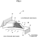
Fig. 1] Fig. 1 is a schematic configuration diagram of a shaft sealing mechanism according to the present invention. - [
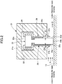
Fig. 2] Fig. 2 is an axial cross-sectional view of the shaft sealing mechanism according to the present invention. - [
Fig. 3] Fig. 3 is an exploded view of a support structure of a thin-plate seal piece. - [
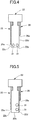
Fig. 4] Fig. 4 is a front view of a thin-plate seal piece in a shaft sealing mechanism according to a first embodiment. - [
Fig. 5] Fig. 5 is a front view of a thin-plate seal piece in a shaft sealing mechanism according to a second embodiment. - [
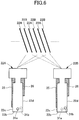
Fig. 6] Fig. 6 is a diagram illustrating an example of an arrangement form of the thin-plate seal pieces. - [
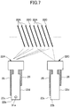
Fig. 7] Fig. 7 is a diagram illustrating another example of an arrangement form of the thin-plate seal pieces. - A shaft sealing mechanism according to the present invention will be described in detail using the drawings.
- As illustrated in
Fig. 1 , ashaft sealing mechanism 11 according to the present invention is applied to, for example, a steam turbine or a gas turbine and is disposed in anannular space 14 formed between arotating shaft 13 and a fixed part (stationary part) 12 such as a casing or stator vanes. - Specifically, as illustrated in
Figs. 1 and2 , on an inner circumferential portion of the fixedpart 12, aseal housing 21, which is an outer shell of theshaft sealing mechanism 11, is disposed annularly alongside the circumferential direction of therotating shaft 13. In addition, formed in an inner circumferential portion of theseal housing 21 is anannular groove 21a, inside of which a large number of thin-plate seal pieces 22 are arranged alongside the circumferential direction of therotating shaft 13. - The outer-circumferential-side proximal ends 22a of the thin-
plate seal pieces 22 are fixed to the inside of theannular groove 21a while the inner-circumferential-side distal ends 22b of the thin-plate seal pieces 22 are in sliding contact with the outer circumferential surface of therotating shaft 13 at a predetermined preload. Here, the thin-plate seal pieces 22 are arranged such that the inner-circumferential-side distal ends 22b, which are free ends, have inclination in the rotational direction with respect to the outer circumferential surface of therotating shaft 13 and form acute angles with the outer circumferential surface. Note that the lower surfaces of the thin-plate seal pieces 22 supported in an inclined manner refer to the surfaces facing the rotatingshaft 13, and the upper surfaces thereof refer to the surfaces opposite from the lower surfaces. - In the
annular space 14 formed between thefixed part 12 and therotating shaft 13, fluid G, such as steam or combustion gas, flows from a high-pressure side to a low-pressure side in the axial direction of therotating shaft 13. For this, theshaft sealing mechanism 11 has an annular seal structure in which multiple layers of the thin-plate seal pieces 22 are arranged in the circumferential direction of therotating shaft 13, and in which the boundary formed by a large number of the thin-plate seal pieces 22 arranged annularly partitions theannular space 14 into a high-pressure-side region being an upstream side in the fluid flowing direction and a low-pressure-side region being an downstream side in the fluid flowing direction. This structure reduces the amount of leakage of the fluid G leaked from the high-pressure-side region to the low-pressure-side region. - Here, as illustrated in
Figs. 2 and3 , each of the thin-plate seal pieces 22 is formed from a flexible material having flexibility and has a flat plate shape with its width dimension being in the axial direction of therotating shaft 13. Specifically, the thin-plate seal piece 22 has a T shape in which the plate width on the proximal end side (the outer-circumferential-sideproximal end 22a) is wider than the plate width on the distal end side (the inner-circumferential-sidedistal end 22b) and is thinned so as to exhibit flexibility. The thin-plate seal pieces 22 are arranged annularly with minute gaps of a certain length therebetween in the circumferential direction of therotating shaft 13. - The proximal end sides of the thin-
plate seal pieces 22 are held between a pair of right and leftretainers plate seal pieces 22, so as to be enclosed from both sides in the plate width direction. Theretainers annular groove 21a of theseal housing 21. - In addition, on the high-pressure side and the low-pressure side of the thin-
plate seal pieces 22, a high-pressure-side plate 25 and a low-pressure-side plate 26 are disposed respectively to function as guide plates for the fluid G. - Specifically, the high-pressure-
side plate 25 having an annular shape is disposed on the left sides (the side positioned on the left inFigs. 2 and3 on the paper) of the thin-plate seal pieces 22, which face the high-pressure-side region. This high-pressure-side plate 25 is disposed adjacent to high-pressure-side side edges 22c of the thin-plate seal pieces 22 facing the high-pressure-side region and is held between the high-pressure-side side edges 22c and theretainer 23. - Here, an inner-circumferential-side
distal end 25a of the high-pressure-side plate 25 extends to an opening edge of theannular groove 21a, but does not reach the inner-circumferential-sidedistal end 22b of the thin-plate seal pieces 22. Moreover, between a high-pressure-side side surface 21b, facing the high-pressure-side region, of theannular groove 21a and the high-pressure-side plate 25, a high-pressure-side gap δH of a certain length is formed in the axial direction of the rotating shaft 13 (the fluid flowing direction, the plate width direction of the seal pieces). - By providing the high-pressure-
side plate 25 in this way, the inner-circumferential-side distal ends 22b of the thin-plate seal pieces 22 are positioned on the inner side of the inner-circumferential-sidedistal end 25a of the high-pressure-side plate 25 in the radial direction of therotating shaft 13. Accordingly, the fluid G flowing in from the high-pressure-side region flows into the distal end sides of the thin-plate seal pieces 22. - Meanwhile, the low-pressure-
side plate 26 in an annular shape is disposed on the right sides (the side positioned on the right inFigs. 2 and3 on the paper) of the thin-plate seal pieces 22, which face the low-pressure-side region. This low-pressure-side plate 26 is disposed adjacent to low-pressure-side side edges 22d, facing the low-pressure-side region, of the thin-plate seal pieces 22 and is held among the low-pressure-side side edges 22d, theretainer 24, and a low-pressure-side side surface 21c, facing the low-pressure-side region, of theannular groove 21a. - Here, an inner-circumferential-side
distal end 26a of the low-pressure-side plate 26 does not reach an opening edge of theannular groove 21a or the inner-circumferential-side distal ends 22b of the thin-plate seal pieces 22 and is positioned on the outer side of the inner-circumferential-sidedistal end 25a of the high-pressure-side plate 25 in the radial direction of therotating shaft 13. In other words, the low-pressure-side plate 26 is shorter than the high-pressure-side plate 25. Moreover, between the low-pressure-side side surface 21c of theannular groove 21a and the low-pressure-side side edges 22d, a low-pressure-side gap δL of a certain length is formed in the axial direction of therotating shaft 13. - The low-pressure-
side plate 26 provided in this way allows the low-pressure-side gap δL to be formed between the low-pressure-side side surface 21c and the low-pressure-side side edges 22d. The low-pressure-side gap δL is formed by the thickness of the low-pressure-side plate 26, and the gap length of the low-pressure-side gap δL can thus be set by adjusting the thickness of the low-pressure-side plate 26. - In addition, the pressure distribution of the fluid G on the upper and lower surfaces of the thin-
plate seal pieces 22 can be set in accordance with the gap lengths of the high-pressure-side gap δH and the low-pressure-side gap δL. Moreover, in accordance with the quantitative relationship between the gap length of the high-pressure-side gap δH and the gap length of the low-pressure-side gap δL, it is possible to set the magnitude of the pressure difference (floating force) due to relative positional difference in the pressure distribution between the upper and lower surfaces of the thin-plate seal pieces 22. - Note that in the
shaft sealing mechanism 11 according to the present invention, the radial gap length between the inner-circumferential-sidedistal end 26a of the low-pressure-side plate 26 and the outer circumferential surface of therotating shaft 13 is designed to be greater than the radial gap length between the inner-circumferential-sidedistal end 25a of the high-pressure-side plate 25 and the outer circumferential surface of therotating shaft 13, in order to yield stable floating force. - With this structure, while the rotating
shaft 13 is not rotating, the inner-circumferential-side distal ends 22b of the thin-plate seal pieces 22 are in contact with the outer circumferential surface of therotating shaft 13 at the predetermined preload. On the other hand, while the rotatingshaft 13 is rotating, the floating force is exerted on the thin-plate seal pieces 22 by the pressure difference due to the relative positional difference in the pressure distribution between the upper and lower surfaces of the thin-plate seal pieces 22 and by the dynamic pressure effect of the fluid G generated by the rotation of therotating shaft 13. This makes the thin-plate seal pieces 22 warped, and accordingly, the inner-circumferential-side distal ends 22b thereof are floated from the outer circumferential surface of therotating shaft 13 and brought into a noncontact state, which prevents abrasion and heat generation of therotating shaft 13 and the thin-plate seal pieces 22. At the same time, the thin-plate seal pieces 22 brought in noncontact with the rotatingshaft 13 reduce the amount of leakage of the fluid G flowing from the high-pressure-side region toward the low-pressure-side region. - Here, as illustrated in
Fig. 4 , multiple pressure conduction holes 31 are formed in the thin-plate seal piece 22. These pressure conduction holes 31 are through holes passing through the upper surface and the lower surface in the thin-plate seal piece 22, and are arranged on an inner side of the inner-circumferential-sidedistal end 26a of the low-pressure-side plate 26 in the radial direction of therotating shaft 13 and alongside the inner-circumferential-sidedistal end 22b in the axial direction of therotating shaft 13. Opening the pressure conduction holes 31 as described above in the thin-plate seal piece 22 allows the fluid G flowing on the upper surface side and the fluid G flowing on the lower surface side to come and go through the pressure conduction holes 31. In other words, the fluid G having the higher pressure, when comparing the pressure of the fluid G flowing alongside the upper surface and the pressure of the fluid G flowing alongside the lower surface, passes through the pressure conduction holes 31 and flows into the side where the pressure of the fluid G is lower. The both pressures eventually become equal to each other. Thus, the pressure of the fluid G flowing between each adjacent thin-plate seal pieces 22 (each minute gap) becomes uniform. - As described above, by forming the pressure conduction holes 31 passing through the thin-
plate seal piece 22 in the thickness direction, it is possible to make the pressure of the fluid G flowing between each adjacent thin-plate seal pieces 22 uniform. Since this eliminates the difference between the pressures of the fluid exerted on the upper and the lower surfaces of the thin-plate seal pieces 22, it is possible to reduce the vibration of the thin-plate seal pieces 22. In this case, since the pressure conduction holes 31 are formed only on the distal end side of the thin-plate seal piece 22, which is an area where vibration occurs, it is possible to obtain proper pressure distributions on the portions on the upper surface and the lower surface on the outer side of the pressure conduction holes 31 in the radial direction of therotating shaft 13, which allows the thin-plate seal piece 22 to float stably as a whole. - Alternatively, the pressure conduction holes 31 may be formed as illustrated in
Fig. 5 in the thin-plate seal piece 22. These pressure conduction holes 31 are arranged on the inner side of the inner-circumferential-sidedistal end 26a of the low-pressure-side plate 26 in the radial direction of therotating shaft 13 and alongside the low-pressure-side side edge 22d in the radial direction of therotating shaft 13. By forming thepressure conduction holes 31 concentratedly only on the low-pressure side, where the vibration is strongest in the thin-plate seal piece 22, as described above, it is possible to reduce the vibration of the thin-plate seal piece 22 efficiently. - Note that when forming the pressure conduction holes 31 in the thin-
plate seal piece 22, the hole positions of the pressure conduction holes 31 formed in adjacent thin-plate pieces 22 are shifted from each other. If the positions of the pressure conduction holes 31 are the same between the adjacent thin-plate seal pieces 22, the pressure conduction holes 21 having the same position form an annular pressure conduction path alongside the circumferential direction of therotating shaft 13. In some cases, the fluid G may flow swiftly in the annular pressure conduction path. As a result, there is a risk that the pressure of the fluid G flowing through each adjacent thin-plate seal pieces 22 cannot be made uniform. - Specifically, as illustrated in
Fig. 6 , in theshaft sealing mechanism 11, thin-plate seal pieces 22A having apressure conduction hole 31a and thin-plate seal pieces 22B having apressure conduction hole 31b are arranged and these thin-plate seal pieces pressure conduction hole 31a is arranged around the center at the inner-circumferential-sidedistal end 22b. On the other hand, thepressure conduction hole 31b is arranged on the low-pressure side of the inner-circumferential-sidedistal end 22b, and on the outer side of thepressure conduction hole 31a in the radial direction of therotating shaft 13. In other words, the hole position of thepressure conduction hole 31a and the hole position of thepressure conduction hole 31b are shifted from each other in the axial direction and the circumferential direction of therotating shaft 13 to prevent the hole openings from overlapping. In addition, when shifting the hole positions, although the shift amount depends on the shapes and sizes of thepressure conduction holes pressure conduction holes - If the hole positions of the pressure conduction holes 31 are the same among all the thin-
plate seal pieces 22, the same effect can be obtained, for example, by providing thin-plate seal pieces 22 having nopressure conduction hole 31 intermittently, each at every other position, or at every third or larger number position, in the multiple thin-plate seal pieces 22 arranged annularly. - Specifically, as illustrated in
Fig. 7 , arranged in theshaft sealing mechanism 11 are thin-plate seal pieces 22A having thepressure conduction hole 31a and thin-plate seal pieces 22C having no pressure conduction hole. The thin-plate seal pieces 22C are arranged, each at every fourth position in the thin-plate seal pieces 22A. In this structure, the hole positions of thepressure conduction holes 31a are the same in the three thin-plate seal pieces 22A consecutively arranged in the circumferential direction of therotating shaft 13, and an annular pressure conduction path is formed, but it is short as an annular pressure conduction path. Hence, even though the fluid G flows in the annular pressure conduction path, the flow hardly affects the action of making uniform the pressure of the fluid G flowing between each adjacent thin-plate seal pieces 22A. - Moreover, by adjusting the number, the inner diameters, the hole positions, the hole shapes, and the like of the pressure conduction holes 31 when forming them in the thin-
plate seal piece 22, it is possible to reduce the vibration of the thin-plate seal piece 22 efficiently while giving a stable floating force to the thin-plate seal piece 22. - The shaft sealing mechanism according to the present invention can increase the life of the seal by controlling the flow direction of the fluid between the thin-plate seal pieces, and can thus be utilized significantly advantageously in continuous operation of a turbine.
-
- 11
- shaft sealing mechanism
- 12
- fixed part
- 13
- rotating shaft
- 14
- annular space
- 21
- seal housing
- 21a
- annular groove
- 21b
- high-pressure-side side surface
- 21c
- low-pressure-side side surface
- 22, 22A to 22C
- thin-plate seal piece
- 22a
- outer-circumferential-side proximal end
- 22b
- inner-circumferential-side proximal end
- 22c
- high-pressure-side side edge
- 22d
- low-pressure-side side edge
- 23, 24
- retainer
- 25
- high-pressure-side plate
- 25a
- inner-circumferential-side distal end
- 26
- low-pressure-side plate
- 26a
- inner-circumferential-side distal end
- 31, 31a, 31b
- pressure conduction hole
- G
- fluid
- δH
- high-pressure-side gap
- δL
- low-pressure-side gap
Claims (5)
- A shaft sealing mechanism that, by being disposed in an annular space formed between a fixed part and a rotating shaft, partitions the annular space into a high-pressure-side region and a low-pressure-side region to prevent fluid from flowing from the high-pressure-side region toward the low-pressure-side region in the annular space in a direction of the rotating shaft, characterized in that the shaft sealing mechanism comprises:an annular seal housing disposed at an inner circumferential portion of the fixed part;a plurality of thin-plate seal pieces stacked and disposed annularly in a circumferential direction of the rotating shaft, each of which has an outer-circumferential-side proximal end fixed to the seal housing, an inner-circumferential-side distal end being a free end and forming an acute angle with an outer circumferential surface of the rotating shaft, and a width dimension in the direction of the rotating shaft; andan annular low-pressure-side plate held between the seal housing and low-pressure-side side edges of the thin-plate seal pieces facing the low-pressure-side region so as to form a gap between the low-pressure-side side edges and the seal housing in the direction of the rotating shaft, whereineach of the thin-plate seal pieces has a pressure conduction hole which is formed on an inner side of an inner-circumferential-side distal end of the low-pressure-side plate in a radial direction of the rotating shaft and allows the fluid flowing on an upper surface side of the thin-plate seal piece and the fluid flowing on a lower surface side of the thin-plate seal piece to pass therethrough.
- The shaft sealing mechanism according to claim 1, characterized in that
the pressure conduction hole is formed alongside the inner-circumferential-side distal end of the thin-plate seal piece. - The shaft sealing mechanism according to claim 1, characterized in that
the pressure conduction hole is formed alongside the low-pressure-side side edge. - The shaft sealing mechanism according to claim 1, characterized in that
hole positions of the pressure conduction holes formed in the thin-plate seal pieces adjacent in the circumferential direction of the rotating shaft are shifted from each other. - The shaft sealing mechanism according to claim 1, characterized in that
thin-plate seal pieces having no pressure conduction hole are arranged intermittently in the circumferential direction of the rotating shaft.
Applications Claiming Priority (2)
| Application Number | Priority Date | Filing Date | Title |
|---|---|---|---|
| JP2014253685A JP6245762B2 (en) | 2014-12-16 | 2014-12-16 | Shaft seal mechanism |
| PCT/JP2015/085001 WO2016098753A1 (en) | 2014-12-16 | 2015-12-15 | Shaft sealing mechanism |
Publications (3)
| Publication Number | Publication Date |
|---|---|
| EP3220019A1 true EP3220019A1 (en) | 2017-09-20 |
| EP3220019A4 EP3220019A4 (en) | 2017-12-27 |
| EP3220019B1 EP3220019B1 (en) | 2020-01-15 |
Family
ID=56126642
Family Applications (1)
| Application Number | Title | Priority Date | Filing Date |
|---|---|---|---|
| EP15869958.7A Active EP3220019B1 (en) | 2014-12-16 | 2015-12-15 | Shaft sealing mechanism |
Country Status (6)
| Country | Link |
|---|---|
| US (1) | US10196987B2 (en) |
| EP (1) | EP3220019B1 (en) |
| JP (1) | JP6245762B2 (en) |
| KR (1) | KR101899272B1 (en) |
| CN (1) | CN107110365B (en) |
| WO (1) | WO2016098753A1 (en) |
Families Citing this family (2)
| Publication number | Priority date | Publication date | Assignee | Title |
|---|---|---|---|---|
| CN112681447B (en) * | 2021-01-06 | 2022-07-05 | 三门核电有限公司 | Nuclear power station plant water pump shaft seal water supply system |
| CN118669185B (en) * | 2024-06-18 | 2025-11-21 | 中国航发沈阳发动机研究所 | Inter-shaft sealing structure with improved main sealing ring |
Family Cites Families (11)
| Publication number | Priority date | Publication date | Assignee | Title |
|---|---|---|---|---|
| CA2359933C (en) * | 2001-02-08 | 2006-03-14 | Mitsubishi Heavy Industries, Ltd. | Shaft seal and gas turbine |
| JP3702212B2 (en) * | 2001-09-28 | 2005-10-05 | 三菱重工業株式会社 | Shaft seal mechanism and turbine |
| CN1324221C (en) * | 2003-05-21 | 2007-07-04 | 三菱重工业株式会社 | Shaft seal mechanism |
| JP3970298B2 (en) * | 2005-11-10 | 2007-09-05 | 三菱重工業株式会社 | Shaft seal mechanism |
| JP5398651B2 (en) * | 2010-06-24 | 2014-01-29 | 三菱重工業株式会社 | Shaft sealing mechanism and rotating machine equipped with the same |
| US9206904B2 (en) * | 2010-07-08 | 2015-12-08 | Siemens Energy, Inc. | Seal including flexible seal strips |
| JP5595259B2 (en) | 2010-12-27 | 2014-09-24 | 三菱重工業株式会社 | Shaft seal device and rotary machine equipped with the same |
| GB201119528D0 (en) * | 2011-11-14 | 2011-12-21 | Rolls Royce Plc | Leaf seal |
| JP5931450B2 (en) * | 2012-01-13 | 2016-06-08 | 三菱重工業株式会社 | Shaft seal device and rotary machine equipped with the same |
| GB201207837D0 (en) * | 2012-05-04 | 2012-06-20 | Rolls Royce Plc | Leaf seal |
| JP6012505B2 (en) * | 2013-02-22 | 2016-10-25 | 三菱重工業株式会社 | Shaft seal device and rotary machine |
-
2014
- 2014-12-16 JP JP2014253685A patent/JP6245762B2/en not_active Expired - Fee Related
-
2015
- 2015-12-15 KR KR1020177016113A patent/KR101899272B1/en not_active Expired - Fee Related
- 2015-12-15 US US15/536,352 patent/US10196987B2/en active Active
- 2015-12-15 CN CN201580068385.8A patent/CN107110365B/en active Active
- 2015-12-15 EP EP15869958.7A patent/EP3220019B1/en active Active
- 2015-12-15 WO PCT/JP2015/085001 patent/WO2016098753A1/en not_active Ceased
Also Published As
| Publication number | Publication date |
|---|---|
| CN107110365A (en) | 2017-08-29 |
| EP3220019A4 (en) | 2017-12-27 |
| JP6245762B2 (en) | 2017-12-13 |
| KR101899272B1 (en) | 2018-09-14 |
| US20170342909A1 (en) | 2017-11-30 |
| JP2016114167A (en) | 2016-06-23 |
| EP3220019B1 (en) | 2020-01-15 |
| WO2016098753A1 (en) | 2016-06-23 |
| US10196987B2 (en) | 2019-02-05 |
| KR20170083129A (en) | 2017-07-17 |
| CN107110365B (en) | 2019-07-23 |
Similar Documents
| Publication | Publication Date | Title |
|---|---|---|
| US7631879B2 (en) | “L” butt gap seal between segments in seal assemblies | |
| EP2444699B1 (en) | Shaft seal and rotary machine with same | |
| US10808752B2 (en) | Sliding members | |
| KR101721348B1 (en) | Shaft seal device and rotary machine | |
| CN103270250A (en) | Shaft sealing device, and rotary machine equipped therewith | |
| US10196987B2 (en) | Shaft sealing mechanism | |
| JP6358976B2 (en) | Turbine sealing device and turbine, and thin plate for sealing device | |
| EP3220018B1 (en) | Shaft sealing mechanism | |
| JP6276209B2 (en) | Turbine sealing device and turbine, and thin plate for sealing device | |
| KR101950127B1 (en) | Shaft seal mechanism | |
| US20130230393A1 (en) | Shaft seal mechanism |
Legal Events
| Date | Code | Title | Description |
|---|---|---|---|
| STAA | Information on the status of an ep patent application or granted ep patent |
Free format text: STATUS: THE INTERNATIONAL PUBLICATION HAS BEEN MADE |
|
| PUAI | Public reference made under article 153(3) epc to a published international application that has entered the european phase |
Free format text: ORIGINAL CODE: 0009012 |
|
| STAA | Information on the status of an ep patent application or granted ep patent |
Free format text: STATUS: REQUEST FOR EXAMINATION WAS MADE |
|
| 17P | Request for examination filed |
Effective date: 20170613 |
|
| AK | Designated contracting states |
Kind code of ref document: A1 Designated state(s): AL AT BE BG CH CY CZ DE DK EE ES FI FR GB GR HR HU IE IS IT LI LT LU LV MC MK MT NL NO PL PT RO RS SE SI SK SM TR |
|
| REG | Reference to a national code |
Ref country code: DE Ref legal event code: R079 Ref document number: 602015045811 Country of ref document: DE Free format text: PREVIOUS MAIN CLASS: F16J0015220000 Ipc: F01D0011000000 |
|
| A4 | Supplementary search report drawn up and despatched |
Effective date: 20171124 |
|
| RIC1 | Information provided on ipc code assigned before grant |
Ipc: F01D 11/00 20060101AFI20171120BHEP Ipc: F16J 15/3284 20160101ALI20171120BHEP |
|
| STAA | Information on the status of an ep patent application or granted ep patent |
Free format text: STATUS: EXAMINATION IS IN PROGRESS |
|
| 17Q | First examination report despatched |
Effective date: 20190103 |
|
| GRAP | Despatch of communication of intention to grant a patent |
Free format text: ORIGINAL CODE: EPIDOSNIGR1 |
|
| STAA | Information on the status of an ep patent application or granted ep patent |
Free format text: STATUS: GRANT OF PATENT IS INTENDED |
|
| INTG | Intention to grant announced |
Effective date: 20190829 |
|
| GRAS | Grant fee paid |
Free format text: ORIGINAL CODE: EPIDOSNIGR3 |
|
| GRAA | (expected) grant |
Free format text: ORIGINAL CODE: 0009210 |
|
| STAA | Information on the status of an ep patent application or granted ep patent |
Free format text: STATUS: THE PATENT HAS BEEN GRANTED |
|
| AK | Designated contracting states |
Kind code of ref document: B1 Designated state(s): AL AT BE BG CH CY CZ DE DK EE ES FI FR GB GR HR HU IE IS IT LI LT LU LV MC MK MT NL NO PL PT RO RS SE SI SK SM TR |
|
| REG | Reference to a national code |
Ref country code: GB Ref legal event code: FG4D Ref country code: CH Ref legal event code: EP |
|
| REG | Reference to a national code |
Ref country code: IE Ref legal event code: FG4D |
|
| REG | Reference to a national code |
Ref country code: DE Ref legal event code: R096 Ref document number: 602015045811 Country of ref document: DE |
|
| REG | Reference to a national code |
Ref country code: AT Ref legal event code: REF Ref document number: 1225319 Country of ref document: AT Kind code of ref document: T Effective date: 20200215 |
|
| REG | Reference to a national code |
Ref country code: NL Ref legal event code: MP Effective date: 20200115 |
|
| REG | Reference to a national code |
Ref country code: LT Ref legal event code: MG4D |
|
| PG25 | Lapsed in a contracting state [announced via postgrant information from national office to epo] |
Ref country code: PT Free format text: LAPSE BECAUSE OF FAILURE TO SUBMIT A TRANSLATION OF THE DESCRIPTION OR TO PAY THE FEE WITHIN THE PRESCRIBED TIME-LIMIT Effective date: 20200607 Ref country code: NL Free format text: LAPSE BECAUSE OF FAILURE TO SUBMIT A TRANSLATION OF THE DESCRIPTION OR TO PAY THE FEE WITHIN THE PRESCRIBED TIME-LIMIT Effective date: 20200115 Ref country code: FI Free format text: LAPSE BECAUSE OF FAILURE TO SUBMIT A TRANSLATION OF THE DESCRIPTION OR TO PAY THE FEE WITHIN THE PRESCRIBED TIME-LIMIT Effective date: 20200115 Ref country code: RS Free format text: LAPSE BECAUSE OF FAILURE TO SUBMIT A TRANSLATION OF THE DESCRIPTION OR TO PAY THE FEE WITHIN THE PRESCRIBED TIME-LIMIT Effective date: 20200115 Ref country code: NO Free format text: LAPSE BECAUSE OF FAILURE TO SUBMIT A TRANSLATION OF THE DESCRIPTION OR TO PAY THE FEE WITHIN THE PRESCRIBED TIME-LIMIT Effective date: 20200415 |
|
| PG25 | Lapsed in a contracting state [announced via postgrant information from national office to epo] |
Ref country code: HR Free format text: LAPSE BECAUSE OF FAILURE TO SUBMIT A TRANSLATION OF THE DESCRIPTION OR TO PAY THE FEE WITHIN THE PRESCRIBED TIME-LIMIT Effective date: 20200115 Ref country code: IS Free format text: LAPSE BECAUSE OF FAILURE TO SUBMIT A TRANSLATION OF THE DESCRIPTION OR TO PAY THE FEE WITHIN THE PRESCRIBED TIME-LIMIT Effective date: 20200515 Ref country code: SE Free format text: LAPSE BECAUSE OF FAILURE TO SUBMIT A TRANSLATION OF THE DESCRIPTION OR TO PAY THE FEE WITHIN THE PRESCRIBED TIME-LIMIT Effective date: 20200115 Ref country code: LV Free format text: LAPSE BECAUSE OF FAILURE TO SUBMIT A TRANSLATION OF THE DESCRIPTION OR TO PAY THE FEE WITHIN THE PRESCRIBED TIME-LIMIT Effective date: 20200115 Ref country code: GR Free format text: LAPSE BECAUSE OF FAILURE TO SUBMIT A TRANSLATION OF THE DESCRIPTION OR TO PAY THE FEE WITHIN THE PRESCRIBED TIME-LIMIT Effective date: 20200416 Ref country code: BG Free format text: LAPSE BECAUSE OF FAILURE TO SUBMIT A TRANSLATION OF THE DESCRIPTION OR TO PAY THE FEE WITHIN THE PRESCRIBED TIME-LIMIT Effective date: 20200415 |
|
| REG | Reference to a national code |
Ref country code: DE Ref legal event code: R082 Ref document number: 602015045811 Country of ref document: DE Representative=s name: HOFFMANN - EITLE PATENT- UND RECHTSANWAELTE PA, DE Ref country code: DE Ref legal event code: R081 Ref document number: 602015045811 Country of ref document: DE Owner name: MITSUBISHI POWER, LTD., JP Free format text: FORMER OWNER: MITSUBISHI HITACHI POWER SYSTEMS, LTD., YOKOHAMA-SHI, KANAGAWA, JP |
|
| REG | Reference to a national code |
Ref country code: DE Ref legal event code: R097 Ref document number: 602015045811 Country of ref document: DE |
|
| PG25 | Lapsed in a contracting state [announced via postgrant information from national office to epo] |
Ref country code: SM Free format text: LAPSE BECAUSE OF FAILURE TO SUBMIT A TRANSLATION OF THE DESCRIPTION OR TO PAY THE FEE WITHIN THE PRESCRIBED TIME-LIMIT Effective date: 20200115 Ref country code: EE Free format text: LAPSE BECAUSE OF FAILURE TO SUBMIT A TRANSLATION OF THE DESCRIPTION OR TO PAY THE FEE WITHIN THE PRESCRIBED TIME-LIMIT Effective date: 20200115 Ref country code: RO Free format text: LAPSE BECAUSE OF FAILURE TO SUBMIT A TRANSLATION OF THE DESCRIPTION OR TO PAY THE FEE WITHIN THE PRESCRIBED TIME-LIMIT Effective date: 20200115 Ref country code: SK Free format text: LAPSE BECAUSE OF FAILURE TO SUBMIT A TRANSLATION OF THE DESCRIPTION OR TO PAY THE FEE WITHIN THE PRESCRIBED TIME-LIMIT Effective date: 20200115 Ref country code: CZ Free format text: LAPSE BECAUSE OF FAILURE TO SUBMIT A TRANSLATION OF THE DESCRIPTION OR TO PAY THE FEE WITHIN THE PRESCRIBED TIME-LIMIT Effective date: 20200115 Ref country code: ES Free format text: LAPSE BECAUSE OF FAILURE TO SUBMIT A TRANSLATION OF THE DESCRIPTION OR TO PAY THE FEE WITHIN THE PRESCRIBED TIME-LIMIT Effective date: 20200115 Ref country code: LT Free format text: LAPSE BECAUSE OF FAILURE TO SUBMIT A TRANSLATION OF THE DESCRIPTION OR TO PAY THE FEE WITHIN THE PRESCRIBED TIME-LIMIT Effective date: 20200115 Ref country code: DK Free format text: LAPSE BECAUSE OF FAILURE TO SUBMIT A TRANSLATION OF THE DESCRIPTION OR TO PAY THE FEE WITHIN THE PRESCRIBED TIME-LIMIT Effective date: 20200115 |
|
| REG | Reference to a national code |
Ref country code: AT Ref legal event code: MK05 Ref document number: 1225319 Country of ref document: AT Kind code of ref document: T Effective date: 20200115 |
|
| PLBE | No opposition filed within time limit |
Free format text: ORIGINAL CODE: 0009261 |
|
| STAA | Information on the status of an ep patent application or granted ep patent |
Free format text: STATUS: NO OPPOSITION FILED WITHIN TIME LIMIT |
|
| PLAA | Information modified related to event that no opposition was filed |
Free format text: ORIGINAL CODE: 0009299DELT |
|
| PLBE | No opposition filed within time limit |
Free format text: ORIGINAL CODE: 0009261 |
|
| 26N | No opposition filed |
Effective date: 20201016 |
|
| R26N | No opposition filed (corrected) |
Effective date: 20201016 |
|
| RAP2 | Party data changed (patent owner data changed or rights of a patent transferred) |
Owner name: MITSUBISHI POWER, LTD. |
|
| PG25 | Lapsed in a contracting state [announced via postgrant information from national office to epo] |
Ref country code: AT Free format text: LAPSE BECAUSE OF FAILURE TO SUBMIT A TRANSLATION OF THE DESCRIPTION OR TO PAY THE FEE WITHIN THE PRESCRIBED TIME-LIMIT Effective date: 20200115 Ref country code: IT Free format text: LAPSE BECAUSE OF FAILURE TO SUBMIT A TRANSLATION OF THE DESCRIPTION OR TO PAY THE FEE WITHIN THE PRESCRIBED TIME-LIMIT Effective date: 20200115 |
|
| PG25 | Lapsed in a contracting state [announced via postgrant information from national office to epo] |
Ref country code: PL Free format text: LAPSE BECAUSE OF FAILURE TO SUBMIT A TRANSLATION OF THE DESCRIPTION OR TO PAY THE FEE WITHIN THE PRESCRIBED TIME-LIMIT Effective date: 20200115 Ref country code: SI Free format text: LAPSE BECAUSE OF FAILURE TO SUBMIT A TRANSLATION OF THE DESCRIPTION OR TO PAY THE FEE WITHIN THE PRESCRIBED TIME-LIMIT Effective date: 20200115 |
|
| REG | Reference to a national code |
Ref country code: CH Ref legal event code: PL |
|
| PG25 | Lapsed in a contracting state [announced via postgrant information from national office to epo] |
Ref country code: MC Free format text: LAPSE BECAUSE OF FAILURE TO SUBMIT A TRANSLATION OF THE DESCRIPTION OR TO PAY THE FEE WITHIN THE PRESCRIBED TIME-LIMIT Effective date: 20200115 |
|
| REG | Reference to a national code |
Ref country code: BE Ref legal event code: MM Effective date: 20201231 |
|
| PG25 | Lapsed in a contracting state [announced via postgrant information from national office to epo] |
Ref country code: FR Free format text: LAPSE BECAUSE OF NON-PAYMENT OF DUE FEES Effective date: 20201231 Ref country code: LU Free format text: LAPSE BECAUSE OF NON-PAYMENT OF DUE FEES Effective date: 20201215 Ref country code: IE Free format text: LAPSE BECAUSE OF NON-PAYMENT OF DUE FEES Effective date: 20201215 |
|
| PG25 | Lapsed in a contracting state [announced via postgrant information from national office to epo] |
Ref country code: CH Free format text: LAPSE BECAUSE OF NON-PAYMENT OF DUE FEES Effective date: 20201231 Ref country code: LI Free format text: LAPSE BECAUSE OF NON-PAYMENT OF DUE FEES Effective date: 20201231 |
|
| PG25 | Lapsed in a contracting state [announced via postgrant information from national office to epo] |
Ref country code: TR Free format text: LAPSE BECAUSE OF FAILURE TO SUBMIT A TRANSLATION OF THE DESCRIPTION OR TO PAY THE FEE WITHIN THE PRESCRIBED TIME-LIMIT Effective date: 20200115 Ref country code: MT Free format text: LAPSE BECAUSE OF FAILURE TO SUBMIT A TRANSLATION OF THE DESCRIPTION OR TO PAY THE FEE WITHIN THE PRESCRIBED TIME-LIMIT Effective date: 20200115 Ref country code: CY Free format text: LAPSE BECAUSE OF FAILURE TO SUBMIT A TRANSLATION OF THE DESCRIPTION OR TO PAY THE FEE WITHIN THE PRESCRIBED TIME-LIMIT Effective date: 20200115 |
|
| PG25 | Lapsed in a contracting state [announced via postgrant information from national office to epo] |
Ref country code: MK Free format text: LAPSE BECAUSE OF FAILURE TO SUBMIT A TRANSLATION OF THE DESCRIPTION OR TO PAY THE FEE WITHIN THE PRESCRIBED TIME-LIMIT Effective date: 20200115 Ref country code: AL Free format text: LAPSE BECAUSE OF FAILURE TO SUBMIT A TRANSLATION OF THE DESCRIPTION OR TO PAY THE FEE WITHIN THE PRESCRIBED TIME-LIMIT Effective date: 20200115 |
|
| PG25 | Lapsed in a contracting state [announced via postgrant information from national office to epo] |
Ref country code: BE Free format text: LAPSE BECAUSE OF NON-PAYMENT OF DUE FEES Effective date: 20201231 |
|
| PGFP | Annual fee paid to national office [announced via postgrant information from national office to epo] |
Ref country code: DE Payment date: 20241029 Year of fee payment: 10 |
|
| PGFP | Annual fee paid to national office [announced via postgrant information from national office to epo] |
Ref country code: GB Payment date: 20241104 Year of fee payment: 10 |