EP3219991A1 - Aligning a centerline of a motor shaft in a fan assembly - Google Patents
Aligning a centerline of a motor shaft in a fan assembly Download PDFInfo
- Publication number
- EP3219991A1 EP3219991A1 EP17161095.9A EP17161095A EP3219991A1 EP 3219991 A1 EP3219991 A1 EP 3219991A1 EP 17161095 A EP17161095 A EP 17161095A EP 3219991 A1 EP3219991 A1 EP 3219991A1
- Authority
- EP
- European Patent Office
- Prior art keywords
- motor
- plate
- direct drive
- drive fan
- fan assembly
- Prior art date
- Legal status (The legal status is an assumption and is not a legal conclusion. Google has not performed a legal analysis and makes no representation as to the accuracy of the status listed.)
- Granted
Links
Images





Classifications
-
- F—MECHANICAL ENGINEERING; LIGHTING; HEATING; WEAPONS; BLASTING
- F04—POSITIVE - DISPLACEMENT MACHINES FOR LIQUIDS; PUMPS FOR LIQUIDS OR ELASTIC FLUIDS
- F04D—NON-POSITIVE-DISPLACEMENT PUMPS
- F04D17/00—Radial-flow pumps, e.g. centrifugal pumps; Helico-centrifugal pumps
- F04D17/08—Centrifugal pumps
- F04D17/16—Centrifugal pumps for displacing without appreciable compression
-
- H—ELECTRICITY
- H02—GENERATION; CONVERSION OR DISTRIBUTION OF ELECTRIC POWER
- H02K—DYNAMO-ELECTRIC MACHINES
- H02K5/00—Casings; Enclosures; Supports
- H02K5/26—Means for adjusting casings relative to their supports
-
- F—MECHANICAL ENGINEERING; LIGHTING; HEATING; WEAPONS; BLASTING
- F04—POSITIVE - DISPLACEMENT MACHINES FOR LIQUIDS; PUMPS FOR LIQUIDS OR ELASTIC FLUIDS
- F04D—NON-POSITIVE-DISPLACEMENT PUMPS
- F04D29/00—Details, component parts, or accessories
- F04D29/60—Mounting; Assembling; Disassembling
- F04D29/601—Mounting; Assembling; Disassembling specially adapted for elastic fluid pumps
-
- F—MECHANICAL ENGINEERING; LIGHTING; HEATING; WEAPONS; BLASTING
- F04—POSITIVE - DISPLACEMENT MACHINES FOR LIQUIDS; PUMPS FOR LIQUIDS OR ELASTIC FLUIDS
- F04D—NON-POSITIVE-DISPLACEMENT PUMPS
- F04D25/00—Pumping installations or systems
- F04D25/02—Units comprising pumps and their driving means
-
- F—MECHANICAL ENGINEERING; LIGHTING; HEATING; WEAPONS; BLASTING
- F04—POSITIVE - DISPLACEMENT MACHINES FOR LIQUIDS; PUMPS FOR LIQUIDS OR ELASTIC FLUIDS
- F04D—NON-POSITIVE-DISPLACEMENT PUMPS
- F04D25/00—Pumping installations or systems
- F04D25/02—Units comprising pumps and their driving means
- F04D25/06—Units comprising pumps and their driving means the pump being electrically driven
-
- F—MECHANICAL ENGINEERING; LIGHTING; HEATING; WEAPONS; BLASTING
- F04—POSITIVE - DISPLACEMENT MACHINES FOR LIQUIDS; PUMPS FOR LIQUIDS OR ELASTIC FLUIDS
- F04D—NON-POSITIVE-DISPLACEMENT PUMPS
- F04D25/00—Pumping installations or systems
- F04D25/02—Units comprising pumps and their driving means
- F04D25/08—Units comprising pumps and their driving means the working fluid being air, e.g. for ventilation
-
- F—MECHANICAL ENGINEERING; LIGHTING; HEATING; WEAPONS; BLASTING
- F04—POSITIVE - DISPLACEMENT MACHINES FOR LIQUIDS; PUMPS FOR LIQUIDS OR ELASTIC FLUIDS
- F04D—NON-POSITIVE-DISPLACEMENT PUMPS
- F04D29/00—Details, component parts, or accessories
- F04D29/05—Shafts or bearings, or assemblies thereof, specially adapted for elastic fluid pumps
- F04D29/053—Shafts
-
- F—MECHANICAL ENGINEERING; LIGHTING; HEATING; WEAPONS; BLASTING
- F04—POSITIVE - DISPLACEMENT MACHINES FOR LIQUIDS; PUMPS FOR LIQUIDS OR ELASTIC FLUIDS
- F04D—NON-POSITIVE-DISPLACEMENT PUMPS
- F04D29/00—Details, component parts, or accessories
- F04D29/60—Mounting; Assembling; Disassembling
- F04D29/62—Mounting; Assembling; Disassembling of radial or helico-centrifugal pumps
- F04D29/624—Mounting; Assembling; Disassembling of radial or helico-centrifugal pumps especially adapted for elastic fluid pumps
- F04D29/626—Mounting or removal of fans
Definitions
- This disclosure relates generally to a fan assembly. More specifically, this disclosure relates to aligning a centerline of a motor shaft in a direct drive fan assembly.
- a direct drive fan assembly has the motor directly driving a fan wheel and does not use belts and/or sheaves to drive the fan wheels.
- Direct drive fans may require a special type of motor that provides high torque at a low speed rpm.
- the motor for a direct drive fan assembly may be physically larger than a motor running at a faster rpm. That is, a direct drive fan assembly may have a large motor that runs slowly.
- Direct drive fan assemblies may be complex with many different parts and/or parts with multiple attachment points (e.g., holes), which have many different variations to accommodate for changing the components of the direct drive fan assembly. Many different parts and attachment points can be combined to make many different variations for each part.
- This disclosure relates generally to a fan assembly. More specifically, this disclosure relates to aligning a centerline of a motor shaft in a direct drive fan assembly.
- the various motors may have different motor heights and the motor shaft may not properly align with a hub in the direct drive fan assembly.
- the motor shaft does not align in the direct drive fan assembly, more components may need to be changed to accommodate the changed motor so as to properly align the motor shaft. This may cause more parts to be combined and/or changed throughout the direct drive fan assembly in order to correct alignment.
- the method for aligning a centerline of a motor shaft in a direct drive fan assembly includes selecting a motor from among a plurality of motors, and matching a motor plate from among a plurality of motor plates to the motor, the matched motor plate is based on the selected motor.
- the method includes creating, from the selected motor and the matching motor plate, a motor-plate assembly that has a resulting height, where the resulting height of the motor-plate assembly corresponds to a particular height of a direct drive fan assembly.
- the method further includes aligning the centerline of the motor-plate assembly to the direct drive fan assembly, where the particular height of the direct drive fan assembly is a constant height.
- a direct drive fan assembly has the motor directly driving a fan wheel and does not use belts and/or sheaves to drive the fan wheels.
- Direct drive fans may require a special type of motor that provides high torque at a low speed rpm.
- a motor for a direct drive fan assembly that operates at a lower rpm may be physically larger than a motor that normally operates at a faster rpm.
- the various motors may differ in height, which may not properly align the motor shaft in the direct drive fan assembly.
- the motor shaft does not align in the direct drive fan assembly, more components need to be changed to accommodate for the changed motor so as to properly align the motor shaft. This may cause more parts to be combined and/or changed throughout the direct drive fan assembly in order to correct alignment.
- direct drive fan assemblies may be complex with many different parts and/or parts with multiple attachment points to provide many different variations.
- some parts may have a plurality of holes to enable parts to be installed in many different locations upon the assembly, which creates many different variations for each part.
- Many parts can cause complications when assembling a direct drive fan assemblies due to the combination of a large number of part types and multiple set of holes.
- the assembly can be further complicated when the fans are assembled incorrectly (e.g., incorrect part and/or hole attachments), which may force a rework of the fan and/or reassembly.
- Aligning the centerline of the motor shaft in the direct drive fan assembly includes changing only a motor and a corresponding motor-plate in the direct drive fan assembly, thereby reducing the number of components that are changed and/or replaced in the direct drive fan assembly. That is, the arrangement of the hub and the frame of the direct drive fan assembly and their sizing can remain unchanged, while a sizing of a motor and/or motor plate are changed.
- the motor and the motor plates can be reused and/or combined in various assemblies to fit a single fan assembly frame and/or fan.
- changing motors in the direct drive fan assembly can be more efficient, less complex, and fewer parts may be manufactured which can lead to cost savings.
- Fig. 1 illustrates a direct drive fan assembly 2 with a motor-plate assembly, according to an embodiment of the disclosure.
- the direct drive fan assembly 2 includes isolator brackets 16, gussets 18, a motor supports 20, two rails 28, an inlet plate 14, a fan 10, and a hub 8, which form a fan assembly base.
- One end of isolator brackets 16 is connected to a side of the gussets 18 and other end of the isolator bracket 16 is connected to the inlet plate 14.
- the gussets 18 are also connected to the inlet plate 14.
- the inlet plate 14 is connected to a first end of the fan 10, while a second end of the fan 10 is connected to the hub 8.
- the fan 10 can have a plurality of blades (not shown) to blow air into the inlet plate 14 and across a motor 4.
- a second end of the gusset 18 is connected to the rail 28, and a motor support 20 connects, for example, perpendicularly to the rails 28.
- a motor support 20 connects, for example, perpendicularly to the rails 28.
- two motor supports 20 are attached perpendicularly to the two rails 28.
- the motor supports 20 may each include a notch 22, described in detail further herein.
- the direct drive fan assembly 2 further includes a motor-plate assembly 24.
- the motor-plate assembly 24 is created from a combination of the motor 4 and a motor plate 6.
- a motor 4 among a plurality of motors can be matched to a motor plate 6 among a plurality of motor plates, the combination of which can form a plurality of different motor-plate assemblies 24 with different heights.
- the motor-plate assembly 24 is mounted and/or attached on top of the motor supports 20 of the direct drive fan assembly 2.
- the centerline 30 is the center of the motor shaft of the motor-plate assembly 24. As illustrated in Figure 1 , the motor shaft of the motor-plate assembly 24 goes along centerline 30, indicating the center of the motor shaft. The centerline 30 of the motor-plate assembly 24 can align with the hub 8 of the direct drive fan assembly 2 to connect the motor shaft to the hub 8.
- the direct drive fan assembly 2 includes a particular height H1 at which the direct drive fan assembly 2 is calibrated.
- the particular height H1 is the distance between the top of the motor supports 20 to the center of the hub 8 or other connection component for connection with the hub 8.
- the particular height H1 can be calibrated based on a predetermined motor 4 size in the direct drive fan assembly 2.
- the particular height H1 can be based on the centerline 30 of a motor shaft of a maximum sized motor 4 that may be intended to be connected to the hub 8. This is so that a particular fan assembly or the direct drive fan assembly 2 can accommodate the largest sized motor which would be used in the direct drive fan assembly 2; Different motor plates 6 may then be employed to provide any adjustment that may be needed when a smaller motor is used in the same type of direct drive fan assembly 2.
- H1 is a constant height based on the size of a predetermined motor 4 in the direct drive fan assembly 2.
- H1 is a constant height based on the size of the fan 8, and H1 will not change by changing the size of the motor 4.
- the plurality of different motor-plate assemblies 24 with different respective motor 4 heights and/or motor plate 6 heights may align the centerline 30 of the motor with the particular height H1 of the direct drive fan assembly 2, as discussed further herein.
- each motor support 20 of the direct drive fan assembly 2 can include a notch 22 in the base frame 20.
- the notches 22 can be utilized to decrease a respective height of the motor-plate assembly 24 relative to the direct drive fan assembly 2.
- the notches 22 can be advantageous such that the motor-plate assemblies can be used across multiple fan assembly 2 sizes.
- the notches 22 can aid in positioning the motor-plate assembly 24 by properly aligning the centerline 30 of the motor shaft with the hub 8 of the direct drive fan assembly 2, as discussed further herein.
- Figs. 2A and 2B illustrate different configurations of motor-plate assemblies, according to an embodiment of the disclosure. For simplicity of the specification, identical features that were previously described will not be described again.
- each motor 4 can have a matching motor plate 6.
- the matching motor plate 6 is inversely related to the particular motor height of the motor 4.
- a tall (e.g., larger) motor 4-2 is matched with a shorter (e.g., smaller) motor plate 6-2 in the direct drive fan assembly 2, while a short (e.g., smaller) motor 4-1 is matched with a tall (e.g., larger) motor plate 6-1. That is, a taller motor 4-2 with a taller motor height MH may be matched with a shorter motor plate 6-2, while a shorter motor 4-1 with a shorter motor height MH may be matched with a taller motor plate 6-1.
- a selected motor 4 will determine the particular matching motor plate 6. That is, the matching motor plate 6 is dependent upon the selected motor 4. For example, the matching motor-plate height PH is less than the motor-plate height PH in response to the different sized motors (e.g., 4-1, 4-2) with different respective motor heights MH.
- the different sized motors e.g., 4-1, 4-2
- the hub e.g., 8 in Figure 1
- the resulting height H2 of the motor-plate assembly 24 will equal the particular height H1 of the direct drive fan assembly 2.
- the motor shaft in various the motor-plate assembly 24 configurations will align to the direct drive fan assembly 2 for proper connection.
- each resulting height H2 among the plurality of configurations of motor-plate assemblies can align the centerline 30 with the direct drive fan assembly 2.
- Figs. 3A - 3E illustrate a plurality of configurations of motors-plate assemblies 24, according to different embodiments of the disclosure.
- motor-plate assemblies 24 with various motors 4-3, 4-4, 4-5, 4-6, 4-7 (generally referred to herein as motors 4) are depicted with various matching motor-plates 6-3, 6-4, 6-5, 6-6, 6-7, etc. (generally referred to herein as motor-plates 6).
- motor-plates 6 The combination of one of the motors 4 and one of the motor plates 6 form a unique motor-plate assembly 24.
- each of the plurality of motors 4 has a particular motor height MH that corresponds to a particular motor plate 6 with a different motor plate height PH.
- the taller the motor 4 e.g., 4-3
- the shorter the matching motor plate 6 e.g., 6-3
- the shorter the motor 4 e.g., 4-7)
- the taller the matching motor plate 6 e.g., 6-7.
- the plurality of motor-plate assemblies 24 are formed from the various combinations between each of the motors 4 and matching motor-plates 6. However, each combination of the plurality of motor-plate assemblies 24 aligns the centerline 30 of the motor shaft with the direct drive fan assembly (e.g., 2 in Figures 1 , 2A, and 2B ).
- the motor-plate assembly 24 has a resulting height H2 of a distance from the centerline 30 of the motor shaft of the motor 4 to the base of the motor plate 6. That is, the distance from the centerline 30 of the motor shaft of the motor 4 to the base of the motor plate 6 defines the resulting height H2.
- the combination of the overall motor height MH and the motor plate height PH may differ, each combination results in the same height H2, as discussed further below.
- a direct drive fan assembly 2 can have a particular height of H1, while a largest/tallest motor 4-3 can be measured from a matching motor plate 6-3 to the centerline 30 of the motor shaft, giving a resulting height of H2. H2 will equal H1. Additionally, or alternatively, a smallest motor 4-7 can be measured from a matching motor plate of 6-7 to the centerline 30 of the motor shaft, giving a resulting height of H2. H2 will equal H1.
- multiple combinations of motors 4 and motor plates 6 can be assembled to create various motor-plate assemblies 24, each of which can align with the direct drive fan assembly for proper operation.
- the alignment of the centerline 30 to the direct drive fan assembly can be advantageous such that when the motor 4 is replaced, only the motor 4 and/or the motor plate 6 may be replaced.
- the direct drive fan assembly 2 components e.g., fan 10, hub 8, isolator bracket 16, motor supports 20, gusset 18, inlet frame 14, etc. shown in Fig. 1 ) maintain the same arrangement and same component sizing.
- a notch 22 in each motor supports 20 may be used to lower the motor-plate assembly 24 to aid in aligning the centerline 30 of the motor shaft with the hub of a relatively shorter direct drive fan assembly 2 and/or when the particular motor-plate assembly 24 exceeds a threshold height, as discussed further herein with respect to Figure 4F .
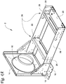
- Fig. 4A illustrates a direct drive fan assembly frame 2, according to an embodiment.
- a direct drive direct drive fan assembly 2 previously described herein is depicted without a motor-plate assembly 24 or a fan 10.
- the notch 22 in each motor support 20 of a relatively short direct drive fan assembly 2 may be used to lower a motor-plate assembly 24 to align the centerline 30 in the short direct drive fan assembly 2, as described further herein with respect to Figure 4F .
- the other parts of the direct drive fan assembly 2 components remain assembled (e.g., unchanged) even when the motor 4 and motor plate 6, which form a motor-plate assembly 24, are changed.
- the other components of the direct drive fan assembly 2 remain in an assembled configuration in the direct drive fan assembly 2, and only the motor-assembly 24 is altered.
- the direct drive fan assembly frame 2 comprised of the fan 10, the inlet plate 14, the isolator brackets 16, the rail 28, the gusset 18, and the motor supports 20, remain assembled in the frame when a motor 4 is changed.
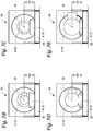
- Figs. 4B - 4E illustrate a plurality of configurations of motors-plate assemblies 24, according to an embodiment. As illustrated in Figs. 4B - 4E , a plurality of motor-plate assemblies 24 combinations are depicted.
- motor 4-8 may be matched with motor plate 6-8, which illustrates a small motor 4-8 matched with a tall motor plate 6-8.
- Each of the combinations of the motor 4 and the motor plate 6 form a unique motor-plate assembly 24.
- Each of the motor-plate assemblies 24 has a resulting height H2, which is the sum from the base of the motor plate 6 to the centerline 30 of the motor 4.
- the predetermined particular height H1 of the direct drive fan assembly 2 is a constant distance (e.g., the center of hub 8 in Figure 1 to top of the motor supports 20).
- the direct drive fan assembly 2 can receive the motor-plate assembly 24 on the placement area 26 of the direct drive fan assembly 2.
- the placement area 26 is on top of the motor supports 20 attached to the rails 28.
- the motor-plate assembly 24 can be securely attached to the placement area 26 via suitable attachments, bolts, screws, or the like, for example.
- Each of the motor-plate assemblies 24 illustrated in Figures 4B - 4E can be placed on the placement area 26 of the direct drive fan assembly 2 of Figure 4A , and each centerline 30 of the motor shaft of the motor-plate assembly would align with the direct drive fan assembly 2 in Figure 4A for proper operation.
- the motor 4 may be changed to a different motor 4, such as for different torque requirements.
- the height of the motor plate 6 may increase in response to a decreased motor 4 size.
- the height of the motor plate 6 may decrease in response to the motor 4 increasing in size (e.g., height).
- the corresponding motors 4 and plates 6 change inversely in response to the respective motor 4 size such that the centerline 30 of the motor shaft aligns with the direct drive fan assembly 2.
- Fig. 4F illustrates a notch in each of the motor supports of the direct drive fan assembly, according to an embodiment of the disclosure.
- Each notch 22 is a slot in a motor support 20 that enables the distance from the center of the hub to the top of the motor support 20 to be lowered (e.g., dropped),thereby increasing the height with the added distance X of the notch placement.
- Each notch 22 can receive a flange from the motor plate 6, such that the flanges of the motor plate 6 slide into the notches 22.
- Each flange of the motor plate 6 may be secured to the notch 22 with a bolt, screw, or like attachments.
- the notches 22 can aid in properly aligning the centerline 30 of the motor shaft using various motors 4 matched to the motor plates 6. That is, different direct drive fan assemblies 2 may change the particular height H1. For instance, a shorter direct drive fan assembly 2 may be set to receive a short (e.g., small) motor 4, the motor 4 may be matched with the smallest motor plate 6. However, the resulting height H2 may still exceed the particular height H1 (e.g., H2 > H1), thereby not allowing the motor 4 to be correctly aligned to a direct drive fan assembly 2.
- the motor-plate assembly 24 may exceed a threshold height such that even matching the motor 4 to a smallest motor plate 6 exceeds the particular height H1 of the direct drive fan assembly.
- a motor 4 with the shortest motor plate may still have a height greater than H1.
- the short direct drive fan assembly 2 can use the notches 22 to modify the required particular height H1.
- the notches 22 lower the base of the motor-plate assembly 24 an additional distance X from its previous position where it was mounted and/or attached to the top of the motor supports 20.
- the required height H2 of the motor-plate assembly 24 is measured from the notch 22 to the center of the hub 8 (H3) instead of from motor supports 20 to the center of the hub 8 (H1) as required in other embodiments when the base of the motor-plate assembly 24 was mounted to the top of the motor supports 20.
- the notches 22 can be used to accommodate different fan sizes and/or changes of the motor 4 (e.g., size). Thus, when the distance from the center of a hub to the top of the motor support 20 of a direct drive fan assembly 2 changes due to a different fan size, the notches 22 can be used to lower the motor-plate assembly 24 to accommodate the particular fan sizes and motor 4 to properly align the centerline 30 of the motor shaft with the hub.
- the notches 22 can be advantageous such that the motor-plate assemblies 24 can be used across multiple fan assembly 2 sizes to keep the H1 and H2 relationship.
- an oversized motor that exceeds the centerline of the maximum motor 4 may utilize the notches 22 to lower the centerline 30 so as to align with the direct drive fan assembly 2.
- the notches 22 are illustrated in the motor support 20 of a short direct drive fan assembly, it will be appreciated that the use of the notch could apply to size changes on the motor plate assembly side.
- the particular height H1 and the resulting height H2 are equal and still align the centerline 30 of the motor shaft with the direct drive fan assembly 2 even though measured from different reference points and minor variance from measuring may be present. That is, measuring from the top of the motor support 20 to the center of the hub (e.g., 8 in Figure 1 ) to determine the particular height H1, or measuring from the notch 22 to the center of the hub to determine the modified particular height H3, may still be equivalent to the resulting H2 that is measured from the base of the motor plate 6 to the centerline 30 of the motor shaft.
- the minor variance that may be present between H2 and H1 (or H3) is deemed to be a deminimus amount and does not impede alignment.
- Fig. 5A illustrates a direct drive fan assembly frame, according to an embodiment of the disclosure.
- a direct drive fan assembly 2 previously described herein is depicted without a motor-plate assembly 24.
- the motor supports 20 of the direct drive fan assembly 2 may include notches (e.g., 22 in Figure 4F ), which may be used to lower the motor-plate assembly 24 to accommodate a motor 4 in a shorter direct fan assembly 2, although the notches 22 may also be used in a taller (e.g., larger) direct drive fan assembly 2.
- the notches 22 can function to align the centerline (e.g., 30 in Figure 1 ) with the hub of the direct drive fan assembly 2 as previously described herein.
- Figs. 5B - 5E illustrate another configuration of a plurality of configurations of motors-plate assemblies, according to a second embodiment of the disclosure.
- the motor 4 can be a particular motor from among a plurality of motors 4-12, 4-13, 4-14, 4-15, etc. (generally referred to herein as motors 4), and each motor 4 among the plurality of motors 4 includes a different height and/or length of a motor frame size that corresponds to a different matching motor plate 6.
- Each of the plurality of motors 4-12, 4-13, 4-14, 4-15 is paired with a one of a plurality of motor-plates 6-12, 6-13, 6-14, 6-15, etc. (generally referred to herein as motor-plates 6) to form a plurality of various combinations of motor-plate assemblies 24.
- the inverse height relationship between the each of the plurality of motors 4 and each of the different matching motor-plates 6 can form different motor-plate assemblies 24 with a centerline 30 of the motor shaft aligning with the direct drive fan assembly 2.
- changing the motor 4 to a different motor 4 may occur, which may result in changing the motor plate 6 to a different motor plate 6 in response to the changed motor 4. That is, the motor plate 6 is dependent upon a selected motor 4.
- the different motor 4 may be matched to a different motor plate 6 to create a different motor-plate assembly 24.
- Various combinations of motor-plate assemblies can be formed in such a manner.
- the motor-plate assembly 24 can have a resulting height H2, which is the sum from the base of the motor plate 6 to the centerline 30 of the motor 4.
- the predetermined particular height H1 of the direct drive fan assembly 2 is a constant distance (e.g., center of hub 8 in Figure 1 to top of motor plate 20).
- Each of the various combinations of motor-plate assemblies 24 can be received on the placement area 26 of the direct drive fan assembly 2, as previously described with respect to Figure 4A .
- the direct drive fan assembly 2 may receive one of the motor-plate assemblies on the placement area 26 and function without additional changes to the frame or support components of the direct drive fan assembly 2 because the centerline 30 of the motor shaft of the motor-plate assembly 24 aligns with the direct drive fan assembly 2.
- Fig. 6 illustrates a method flow chart of an embodiment of the disclosure.
- the method 34 describes aligning a centerline of a motor shaft in a direct drive fan assembly while minimizing components.
- the method 34 includes setting a particular height H1 of a direct drive fan assembly, wherein the particular height is a constant height from a base of the direct drive fan assembly to a center of the direct drive fan assembly.
- the particular height H1 is measured from a top of a motor support to a center of a hub of a direct drive fan assembly.
- the particular height H1 can be based on a largest motor size available that the direct drive fan assembly can accommodate.
- the method 34 includes selecting a motor from among a plurality of motors for a direct drive fan assembly.
- the selected motor can be a tall motor or a short motor, depending upon the specific direct drive fan assembly.
- Each of the plurality of motors has a particular motor height.
- the particular motor height can correspond to the size of the selected motor. For example, a larger motor can be taller than a smaller motor, which may be shorter.
- the method 34 includes matching a motor plate to the selected motor to form a motor and plate assembly, the matched motor plate is based on the particular motor height of the selected motor. That is, the selected motor determines a corresponding motor-plate. For example, the motor height MH determines which motor plate height PH is matched to form the motor-plate assembly.
- the resulting height H2 from the centerline of the motor to the base of the motor plate is equal to the particular height H1 of the direct drive fan assembly.
- the method 34 includes aligning the centerline of the motor shaft of the motor-plate assembly to the direct drive fan assembly.
- the motor-plate assembly can be installed in the direct drive fan assembly for operation. Many different combinations of motor-plate assemblies can operate within the direct drive fan assembly without replacing additional components of the direct drive fan assembly, as previously described herein.
- any of aspects 1 - 10 can be combined with any of aspects 11 - 20 and any of aspects 11 - 16 can be combined with any of aspects 17 - 20.
Landscapes
- Engineering & Computer Science (AREA)
- General Engineering & Computer Science (AREA)
- Mechanical Engineering (AREA)
- Power Engineering (AREA)
- Structures Of Non-Positive Displacement Pumps (AREA)
- Connection Of Motors, Electrical Generators, Mechanical Devices, And The Like (AREA)
Abstract
Description
- This disclosure relates generally to a fan assembly. More specifically, this disclosure relates to aligning a centerline of a motor shaft in a direct drive fan assembly.
- A direct drive fan assembly has the motor directly driving a fan wheel and does not use belts and/or sheaves to drive the fan wheels. Direct drive fans may require a special type of motor that provides high torque at a low speed rpm. However, the motor for a direct drive fan assembly may be physically larger than a motor running at a faster rpm. That is, a direct drive fan assembly may have a large motor that runs slowly.
- Direct drive fan assemblies may be complex with many different parts and/or parts with multiple attachment points (e.g., holes), which have many different variations to accommodate for changing the components of the direct drive fan assembly. Many different parts and attachment points can be combined to make many different variations for each part.
- This disclosure relates generally to a fan assembly. More specifically, this disclosure relates to aligning a centerline of a motor shaft in a direct drive fan assembly.
- As different motors are changed within the direct drive fan assembly, the various motors may have different motor heights and the motor shaft may not properly align with a hub in the direct drive fan assembly. When the motor shaft does not align in the direct drive fan assembly, more components may need to be changed to accommodate the changed motor so as to properly align the motor shaft. This may cause more parts to be combined and/or changed throughout the direct drive fan assembly in order to correct alignment.
- As disclosed herein, a method for aligning a centerline of a motor shaft in a direct drive fan assembly is disclosed. In an embodiment, the method for aligning a centerline of a motor shaft in a direct drive fan assembly includes selecting a motor from among a plurality of motors, and matching a motor plate from among a plurality of motor plates to the motor, the matched motor plate is based on the selected motor. The method includes creating, from the selected motor and the matching motor plate, a motor-plate assembly that has a resulting height, where the resulting height of the motor-plate assembly corresponds to a particular height of a direct drive fan assembly. The method further includes aligning the centerline of the motor-plate assembly to the direct drive fan assembly, where the particular height of the direct drive fan assembly is a constant height.
- Reference is now made to the drawings in which like reference numbers represent corresponding parts throughout.
-
Fig. 1 illustrates a direct drive fan assembly with a motor-plate assembly, according to an embodiment of the disclosure. -
Figs. 2A and 2B illustrate different configurations of motor-plate assemblies, according to an embodiment of the disclosure. -
Figs. 3A - 3E illustrate a plurality of configurations of motors-plate assemblies, according to different embodiments of the disclosure. -
Fig. 4A illustrates a direct drive fan assembly frame, according to an embodiment of the disclosure. -
Figs. 4B - 4E illustrate a plurality of configurations of motors-plate assemblies, according to an embodiment of the disclosure. -
Fig. 4F illustrates notches in the motor supports of the direct drive fan assembly, according to an embodiment of the disclosure. -
Fig. 5A illustrates a direct drive fan assembly frame, according to an embodiment of the disclosure. -
Figs. 5B - 5E illustrate another configuration of a plurality of configurations of motors-plate assemblies, according to a second embodiment of the disclosure. -
Fig. 6 illustrates a method flowchart of an embodiment of the disclosure. - A direct drive fan assembly has the motor directly driving a fan wheel and does not use belts and/or sheaves to drive the fan wheels. Direct drive fans may require a special type of motor that provides high torque at a low speed rpm. However, a motor for a direct drive fan assembly that operates at a lower rpm may be physically larger than a motor that normally operates at a faster rpm.
- As different motors are changed within the direct drive fan assembly, the various motors may differ in height, which may not properly align the motor shaft in the direct drive fan assembly. When the motor shaft does not align in the direct drive fan assembly, more components need to be changed to accommodate for the changed motor so as to properly align the motor shaft. This may cause more parts to be combined and/or changed throughout the direct drive fan assembly in order to correct alignment.
- As a result, direct drive fan assemblies may be complex with many different parts and/or parts with multiple attachment points to provide many different variations. For example, some parts may have a plurality of holes to enable parts to be installed in many different locations upon the assembly, which creates many different variations for each part. Many parts can cause complications when assembling a direct drive fan assemblies due to the combination of a large number of part types and multiple set of holes. The assembly can be further complicated when the fans are assembled incorrectly (e.g., incorrect part and/or hole attachments), which may force a rework of the fan and/or reassembly.
- As disclosed herein, a method for aligning a centerline of a motor shaft in a direct drive fan assembly while minimizing components is described. Aligning the centerline of the motor shaft in the direct drive fan assembly includes changing only a motor and a corresponding motor-plate in the direct drive fan assembly, thereby reducing the number of components that are changed and/or replaced in the direct drive fan assembly. That is, the arrangement of the hub and the frame of the direct drive fan assembly and their sizing can remain unchanged, while a sizing of a motor and/or motor plate are changed. The motor and the motor plates can be reused and/or combined in various assemblies to fit a single fan assembly frame and/or fan.
- By limiting the number of components (e.g., the motor and the motor-plate) that are changed in the direct drive fan assembly, changing motors in the direct drive fan assembly can be more efficient, less complex, and fewer parts may be manufactured which can lead to cost savings.
-
Fig. 1 illustrates a directdrive fan assembly 2 with a motor-plate assembly, according to an embodiment of the disclosure. The directdrive fan assembly 2 includesisolator brackets 16,gussets 18, a motor supports 20, tworails 28, aninlet plate 14, afan 10, and ahub 8, which form a fan assembly base. One end ofisolator brackets 16 is connected to a side of thegussets 18 and other end of theisolator bracket 16 is connected to theinlet plate 14. Thegussets 18 are also connected to theinlet plate 14. Theinlet plate 14 is connected to a first end of thefan 10, while a second end of thefan 10 is connected to thehub 8. Thefan 10 can have a plurality of blades (not shown) to blow air into theinlet plate 14 and across amotor 4. A second end of thegusset 18 is connected to therail 28, and amotor support 20 connects, for example, perpendicularly to therails 28. As illustrated inFigure 1 , two motor supports 20 are attached perpendicularly to the tworails 28. The motor supports 20 may each include anotch 22, described in detail further herein. - The direct
drive fan assembly 2 further includes a motor-plate assembly 24. The motor-plate assembly 24 is created from a combination of themotor 4 and amotor plate 6. Amotor 4 among a plurality of motors can be matched to amotor plate 6 among a plurality of motor plates, the combination of which can form a plurality of different motor-plate assemblies 24 with different heights. The motor-plate assembly 24 is mounted and/or attached on top of the motor supports 20 of the directdrive fan assembly 2. - The
centerline 30 is the center of the motor shaft of the motor-plate assembly 24. As illustrated inFigure 1 , the motor shaft of the motor-plate assembly 24 goes alongcenterline 30, indicating the center of the motor shaft. Thecenterline 30 of the motor-plate assembly 24 can align with thehub 8 of the directdrive fan assembly 2 to connect the motor shaft to thehub 8. The directdrive fan assembly 2 includes a particular height H1 at which the directdrive fan assembly 2 is calibrated. The particular height H1 is the distance between the top of the motor supports 20 to the center of thehub 8 or other connection component for connection with thehub 8. For example, the particular height H1 can be calibrated based on apredetermined motor 4 size in the directdrive fan assembly 2. In an embodiment, the particular height H1 can be based on thecenterline 30 of a motor shaft of a maximumsized motor 4 that may be intended to be connected to thehub 8. This is so that a particular fan assembly or the directdrive fan assembly 2 can accommodate the largest sized motor which would be used in the directdrive fan assembly 2;Different motor plates 6 may then be employed to provide any adjustment that may be needed when a smaller motor is used in the same type of directdrive fan assembly 2. In other words, H1 is a constant height based on the size of apredetermined motor 4 in the directdrive fan assembly 2. H1 is a constant height based on the size of thefan 8, and H1 will not change by changing the size of themotor 4. In some embodiments, the plurality of different motor-plate assemblies 24 with differentrespective motor 4 heights and/ormotor plate 6 heights may align thecenterline 30 of the motor with the particular height H1 of the directdrive fan assembly 2, as discussed further herein. - In an embodiment, each
motor support 20 of the directdrive fan assembly 2 can include anotch 22 in thebase frame 20. Thenotches 22 can be utilized to decrease a respective height of the motor-plate assembly 24 relative to the directdrive fan assembly 2. Thenotches 22 can be advantageous such that the motor-plate assemblies can be used acrossmultiple fan assembly 2 sizes. Thenotches 22 can aid in positioning the motor-plate assembly 24 by properly aligning thecenterline 30 of the motor shaft with thehub 8 of the directdrive fan assembly 2, as discussed further herein. -
Figs. 2A and 2B illustrate different configurations of motor-plate assemblies, according to an embodiment of the disclosure. For simplicity of the specification, identical features that were previously described will not be described again. - As described herein, each
motor 4 can have a matchingmotor plate 6. The matchingmotor plate 6 is inversely related to the particular motor height of themotor 4. As illustrated inFigures 2A and 2B , a tall (e.g., larger) motor 4-2 is matched with a shorter (e.g., smaller) motor plate 6-2 in the directdrive fan assembly 2, while a short (e.g., smaller) motor 4-1 is matched with a tall (e.g., larger) motor plate 6-1. That is, a taller motor 4-2 with a taller motor height MH may be matched with a shorter motor plate 6-2, while a shorter motor 4-1 with a shorter motor height MH may be matched with a taller motor plate 6-1. A selectedmotor 4 will determine the particularmatching motor plate 6. That is, the matchingmotor plate 6 is dependent upon the selectedmotor 4. For example, the matching motor-plate height PH is less than the motor-plate height PH in response to the different sized motors (e.g., 4-1, 4-2) with different respective motor heights MH. - Although each of the motor-
plate assemblies 24 is a combination of different sized components (e.g.,motor 4, motor plate 6), a resulting height H2 (shown inFigures 3A - 3E ) of the base of the motor plate to thecenterline 30 of the shaft of themotor 4 for each embodiment, is equal to the particular height H1 (shown inFigure 1 ) in the direct drive fan assembly 2 (e.g., H2 = H1). While different motor-plate assemblies 24 may vary (e.g., differentsized motors 4, different sized motor-plates 6), the motor-plate assemblies 24 are assembled such that thecenterline 30 of the motor shaft will align and connect with the hub (e.g., 8 inFigure 1 ) of the directdrive fan assembly 2. In other words, the particular height H1 of the directdrive fan assembly 2 is equal to the resulting height H2 of the motor-plate assembly 24 (e.g., H2= H1 as illustrated inFigures 3A - 3E ), thereby aligning thecenterline 30 to the hub of the directdrive fan assembly 2. Thus, regardless of themotor 4 and/or themotor plate 6 changing in the directdrive fan assembly 2, the resulting height H2 of the motor-plate assembly 24 will equal the particular height H1 of the directdrive fan assembly 2. The motor shaft in various the motor-plate assembly 24 configurations will align to the directdrive fan assembly 2 for proper connection. - As described further herein, each resulting height H2 among the plurality of configurations of motor-plate assemblies (e.g., 24) can align the
centerline 30 with the directdrive fan assembly 2. -
Figs. 3A - 3E illustrate a plurality of configurations of motors-plate assemblies 24, according to different embodiments of the disclosure. - As illustrated in
Figures 3A - 3E , a plurality of motor-plate assemblies 24 with various motors 4-3, 4-4, 4-5, 4-6, 4-7 (generally referred to herein as motors 4) are depicted with various matching motor-plates 6-3, 6-4, 6-5, 6-6, 6-7, etc. (generally referred to herein as motor-plates 6). The combination of one of themotors 4 and one of themotor plates 6 form a unique motor-plate assembly 24. - As previously described herein, the
motor 4 height (e.g., MH inFigs. 2A and 2B ) and the matchingmotor plate 6 height (e.g., PH inFigures 2A and 2B ) are inversely related. As illustrated inFigures 3A - 3E , each of the plurality ofmotors 4 has a particular motor height MH that corresponds to aparticular motor plate 6 with a different motor plate height PH. For instance, the taller the motor 4 (e.g., 4-3), the shorter the matching motor plate 6 (e.g., 6-3). Alternatively, the shorter the motor 4 (e.g., 4-7), the taller the matching motor plate 6 (e.g., 6-7). - The plurality of motor-
plate assemblies 24 are formed from the various combinations between each of themotors 4 and matching motor-plates 6. However, each combination of the plurality of motor-plate assemblies 24 aligns thecenterline 30 of the motor shaft with the direct drive fan assembly (e.g., 2 inFigures 1 ,2A, and 2B ). The motor-plate assembly 24 has a resulting height H2 of a distance from thecenterline 30 of the motor shaft of themotor 4 to the base of themotor plate 6. That is, the distance from thecenterline 30 of the motor shaft of themotor 4 to the base of themotor plate 6 defines the resulting height H2. As illustrated inFigures 3A - 3E , although the combination of the overall motor height MH and the motor plate height PH may differ, each combination results in the same height H2, as discussed further below. - For example, a direct
drive fan assembly 2 can have a particular height of H1, while a largest/tallest motor 4-3 can be measured from a matching motor plate 6-3 to thecenterline 30 of the motor shaft, giving a resulting height of H2. H2 will equal H1. Additionally, or alternatively, a smallest motor 4-7 can be measured from a matching motor plate of 6-7 to thecenterline 30 of the motor shaft, giving a resulting height of H2. H2 will equal H1. As such, multiple combinations ofmotors 4 andmotor plates 6 can be assembled to create various motor-plate assemblies 24, each of which can align with the direct drive fan assembly for proper operation. - The alignment of the
centerline 30 to the direct drive fan assembly can be advantageous such that when themotor 4 is replaced, only themotor 4 and/or themotor plate 6 may be replaced. The directdrive fan assembly 2 components (e.g.,fan 10,hub 8,isolator bracket 16, motor supports 20,gusset 18,inlet frame 14, etc. shown inFig. 1 ) maintain the same arrangement and same component sizing. - In some embodiments, a
notch 22 in each motor supports 20 may be used to lower the motor-plate assembly 24 to aid in aligning thecenterline 30 of the motor shaft with the hub of a relatively shorter directdrive fan assembly 2 and/or when the particular motor-plate assembly 24 exceeds a threshold height, as discussed further herein with respect toFigure 4F . -
Fig. 4A illustrates a direct drivefan assembly frame 2, according to an embodiment. A direct drive directdrive fan assembly 2 previously described herein is depicted without a motor-plate assembly 24 or afan 10. In some embodiments, thenotch 22 in eachmotor support 20 of a relatively short directdrive fan assembly 2 may be used to lower a motor-plate assembly 24 to align thecenterline 30 in the short directdrive fan assembly 2, as described further herein with respect toFigure 4F . - As shown in
Figure 4A , the other parts of the directdrive fan assembly 2 components remain assembled (e.g., unchanged) even when themotor 4 andmotor plate 6, which form a motor-plate assembly 24, are changed. In other words, although amotor 4 and/or amotor plate 6 may be changed for a different motor-plate assembly 24, the other components of the directdrive fan assembly 2 remain in an assembled configuration in the directdrive fan assembly 2, and only the motor-assembly 24 is altered. For instance, the direct drivefan assembly frame 2 comprised of thefan 10, theinlet plate 14, theisolator brackets 16, therail 28, thegusset 18, and the motor supports 20, remain assembled in the frame when amotor 4 is changed. -
Figs. 4B - 4E illustrate a plurality of configurations of motors-plate assemblies 24, according to an embodiment. As illustrated inFigs. 4B - 4E , a plurality of motor-plate assemblies 24 combinations are depicted. For example, motor 4-8 may be matched with motor plate 6-8, which illustrates a small motor 4-8 matched with a tall motor plate 6-8. - Each of the combinations of the
motor 4 and themotor plate 6 form a unique motor-plate assembly 24. Each of the motor-plate assemblies 24 has a resulting height H2, which is the sum from the base of themotor plate 6 to thecenterline 30 of themotor 4. The predetermined particular height H1 of the directdrive fan assembly 2 is a constant distance (e.g., the center ofhub 8 inFigure 1 to top of the motor supports 20). As such, the resulting height H2 of the motor-plate assembly 24 is equal to the particular height H1 (H2 = H1) such that thecenterline 30 aligns with the hub of the directdrive fan assembly 2. - In an embodiment, the direct
drive fan assembly 2 can receive the motor-plate assembly 24 on theplacement area 26 of the directdrive fan assembly 2. Theplacement area 26 is on top of the motor supports 20 attached to therails 28. The motor-plate assembly 24 can be securely attached to theplacement area 26 via suitable attachments, bolts, screws, or the like, for example. Each of the motor-plate assemblies 24 illustrated inFigures 4B - 4E can be placed on theplacement area 26 of the directdrive fan assembly 2 ofFigure 4A , and eachcenterline 30 of the motor shaft of the motor-plate assembly would align with the directdrive fan assembly 2 inFigure 4A for proper operation. - In some embodiments, the
motor 4 may be changed to adifferent motor 4, such as for different torque requirements. When amotor 4 is changed in the motor-plate assembly 24, the height of themotor plate 6 may increase in response to a decreasedmotor 4 size. Alternatively, the height of themotor plate 6 may decrease in response to themotor 4 increasing in size (e.g., height). The correspondingmotors 4 andplates 6 change inversely in response to therespective motor 4 size such that thecenterline 30 of the motor shaft aligns with the directdrive fan assembly 2. -
Fig. 4F illustrates a notch in each of the motor supports of the direct drive fan assembly, according to an embodiment of the disclosure. - Each
notch 22 is a slot in amotor support 20 that enables the distance from the center of the hub to the top of themotor support 20 to be lowered (e.g., dropped),thereby increasing the height with the added distance X of the notch placement. Eachnotch 22 can receive a flange from themotor plate 6, such that the flanges of themotor plate 6 slide into thenotches 22. Each flange of themotor plate 6 may be secured to thenotch 22 with a bolt, screw, or like attachments. - The
notches 22 can aid in properly aligning thecenterline 30 of the motor shaft usingvarious motors 4 matched to themotor plates 6. That is, different directdrive fan assemblies 2 may change the particular height H1. For instance, a shorter directdrive fan assembly 2 may be set to receive a short (e.g., small)motor 4, themotor 4 may be matched with thesmallest motor plate 6. However, the resulting height H2 may still exceed the particular height H1 (e.g., H2 > H1), thereby not allowing themotor 4 to be correctly aligned to a directdrive fan assembly 2. The motor-plate assembly 24 may exceed a threshold height such that even matching themotor 4 to asmallest motor plate 6 exceeds the particular height H1 of the direct drive fan assembly. In these instances, thenotches 22 may be used to modify the particular height H1 to a modified height H3 that is equal to the sum of the original height of H1 and a distance X (e.g., H3 = H1 + X). For example, in a short directdrive fan assembly 2, the resulting height H2 of the motor-plate assemblies 24 as previously discussed with respect toFigs. 3A - 3E may not be equivalent to the particular height H1 of the short directdrive fan assembly 2 due to a lowering of the center of the hub of smaller (shorter) fan. Amotor 4 with the shortest motor plate may still have a height greater than H1. To accommodate the short (e.g., smaller) directdrive fan assembly 2, thenotches 22 may be used to modify the particular height H1 of the direct drive fan assembly and the resulting height H2 of the motor-plate assembly 24 to maintain the H1=H2 relationship. - As illustrated in
Figure 4F , the short directdrive fan assembly 2 can use thenotches 22 to modify the required particular height H1. The modified particular height H3 of the directdrive fan assembly 2 can be the sum of a distance measured from the center of thehub 30 of the directdrive fan assembly 2 to the top of the motor support 20 (illustrated inFigure 4F as H1, which is the original height as shown inFigure 1 ) and a distance from the top of themotor support 20 to the notch 22 (illustrated inFigure 4F as X) (e.g., H1 + X = H3). Accordingly, thenotches 22 lower the base of the motor-plate assembly 24 an additional distance X from its previous position where it was mounted and/or attached to the top of the motor supports 20. As such, the required height H2 of the motor-plate assembly 24 is measured from thenotch 22 to the center of the hub 8 (H3) instead of from motor supports 20 to the center of the hub 8 (H1) as required in other embodiments when the base of the motor-plate assembly 24 was mounted to the top of the motor supports 20. - The
notches 22 can be used to accommodate different fan sizes and/or changes of the motor 4 (e.g., size). Thus, when the distance from the center of a hub to the top of themotor support 20 of a directdrive fan assembly 2 changes due to a different fan size, thenotches 22 can be used to lower the motor-plate assembly 24 to accommodate the particular fan sizes andmotor 4 to properly align thecenterline 30 of the motor shaft with the hub. Thenotches 22 can be advantageous such that the motor-plate assemblies 24 can be used acrossmultiple fan assembly 2 sizes to keep the H1 and H2 relationship. - Alternatively, in some embodiments, an oversized motor that exceeds the centerline of the
maximum motor 4 may utilize thenotches 22 to lower thecenterline 30 so as to align with the directdrive fan assembly 2. Although thenotches 22 are illustrated in themotor support 20 of a short direct drive fan assembly, it will be appreciated that the use of the notch could apply to size changes on the motor plate assembly side. - It may be appreciated that the particular height H1 and the resulting height H2 are equal and still align the
centerline 30 of the motor shaft with the directdrive fan assembly 2 even though measured from different reference points and minor variance from measuring may be present. That is, measuring from the top of themotor support 20 to the center of the hub (e.g., 8 inFigure 1 ) to determine the particular height H1, or measuring from thenotch 22 to the center of the hub to determine the modified particular height H3, may still be equivalent to the resulting H2 that is measured from the base of themotor plate 6 to thecenterline 30 of the motor shaft. The minor variance that may be present between H2 and H1 (or H3) is deemed to be a deminimus amount and does not impede alignment. -
Fig. 5A illustrates a direct drive fan assembly frame, according to an embodiment of the disclosure. A directdrive fan assembly 2 previously described herein is depicted without a motor-plate assembly 24. As previously described herein, in some embodiments, the motor supports 20 of the directdrive fan assembly 2 may include notches (e.g., 22 inFigure 4F ), which may be used to lower the motor-plate assembly 24 to accommodate amotor 4 in a shorterdirect fan assembly 2, although thenotches 22 may also be used in a taller (e.g., larger) directdrive fan assembly 2. Thenotches 22 can function to align the centerline (e.g., 30 inFigure 1 ) with the hub of the directdrive fan assembly 2 as previously described herein. -
Figs. 5B - 5E illustrate another configuration of a plurality of configurations of motors-plate assemblies, according to a second embodiment of the disclosure. Similar toFigure 4B , as illustrated inFigure 5B , themotor 4 can be a particular motor from among a plurality of motors 4-12, 4-13, 4-14, 4-15, etc. (generally referred to herein as motors 4), and eachmotor 4 among the plurality ofmotors 4 includes a different height and/or length of a motor frame size that corresponds to a differentmatching motor plate 6. - Each of the plurality of motors 4-12, 4-13, 4-14, 4-15 is paired with a one of a plurality of motor-plates 6-12, 6-13, 6-14, 6-15, etc. (generally referred to herein as motor-plates 6) to form a plurality of various combinations of motor-
plate assemblies 24. The inverse height relationship between the each of the plurality ofmotors 4 and each of the different matching motor-plates 6 can form different motor-plate assemblies 24 with acenterline 30 of the motor shaft aligning with the directdrive fan assembly 2. - In some embodiments, changing the
motor 4 to adifferent motor 4 may occur, which may result in changing themotor plate 6 to adifferent motor plate 6 in response to the changedmotor 4. That is, themotor plate 6 is dependent upon a selectedmotor 4. Thedifferent motor 4 may be matched to adifferent motor plate 6 to create a different motor-plate assembly 24. Various combinations of motor-plate assemblies can be formed in such a manner. - While each
motor 4 and themotor plate 6 may vary in height, the motor-plate assembly 24 can have a resulting height H2, which is the sum from the base of themotor plate 6 to thecenterline 30 of themotor 4. The predetermined particular height H1 of the directdrive fan assembly 2 is a constant distance (e.g., center ofhub 8 inFigure 1 to top of motor plate 20). As such, the resulting height H2 of the motor-plate assembly 24 is equal to the particular height H1 (H2 = H1) such that thecenterline 30 aligns with the directdrive fan assembly 2. - Each of the various combinations of motor-
plate assemblies 24 can be received on theplacement area 26 of the directdrive fan assembly 2, as previously described with respect toFigure 4A . The directdrive fan assembly 2 may receive one of the motor-plate assemblies on theplacement area 26 and function without additional changes to the frame or support components of the directdrive fan assembly 2 because thecenterline 30 of the motor shaft of the motor-plate assembly 24 aligns with the directdrive fan assembly 2. -
Fig. 6 illustrates a method flow chart of an embodiment of the disclosure. Themethod 34 describes aligning a centerline of a motor shaft in a direct drive fan assembly while minimizing components. - At
box 36, themethod 34 includes setting a particular height H1 of a direct drive fan assembly, wherein the particular height is a constant height from a base of the direct drive fan assembly to a center of the direct drive fan assembly. The particular height H1 is measured from a top of a motor support to a center of a hub of a direct drive fan assembly. The particular height H1 can be based on a largest motor size available that the direct drive fan assembly can accommodate. - At
box 38, themethod 34 includes selecting a motor from among a plurality of motors for a direct drive fan assembly. For instance, the selected motor can be a tall motor or a short motor, depending upon the specific direct drive fan assembly. Each of the plurality of motors has a particular motor height. The particular motor height can correspond to the size of the selected motor. For example, a larger motor can be taller than a smaller motor, which may be shorter. - At
box 40, themethod 34 includes matching a motor plate to the selected motor to form a motor and plate assembly, the matched motor plate is based on the particular motor height of the selected motor. That is, the selected motor determines a corresponding motor-plate. For example, the motor height MH determines which motor plate height PH is matched to form the motor-plate assembly. The resulting height H2 from the centerline of the motor to the base of the motor plate is equal to the particular height H1 of the direct drive fan assembly. As such, the resulting height H2 of the motor-plate assembly is equal to the particular height H1 (H2=H1), such that the centerline is aligned with the direct drive fan assembly for proper operation. - At
box 42, themethod 34 includes aligning the centerline of the motor shaft of the motor-plate assembly to the direct drive fan assembly. The motor-plate assembly can be installed in the direct drive fan assembly for operation. Many different combinations of motor-plate assemblies can operate within the direct drive fan assembly without replacing additional components of the direct drive fan assembly, as previously described herein. - Any of aspects 1 - 10 can be combined with any of aspects 11 - 20 and any of aspects 11 - 16 can be combined with any of aspects 17 - 20.
- Aspect 1. A method for aligning a centerline of a motor shaft in a direct drive fan assembly, the direct drive fan assembly includes a motor, a motor shaft, and a fan, comprising:
- selecting a motor from among a plurality of motors;
- matching a motor plate from among a plurality of motor plates to the motor, the matched motor plate is based on the selected motor,
- creating, from the selected motor and the matching motor plate, a motor-plate assembly that has a resulting height, wherein the resulting height of the motor-plate assembly corresponds to a particular height of a direct drive fan assembly;
- aligning a centerline of a motor shaft of the motor-plate assembly to the direct drive fan assembly, wherein the particular height of the direct drive fan assembly is constant.
-
Aspect 2. The method of aspect 1, wherein:- each motor among the plurality of motors has a particular motor height,
- each motor plate among the plurality of motor plates has a particular motor plate height, and
- wherein the particular motor height of the selected motor inversely corresponds to the particular plate height of the matching motor plate.
- Aspect 3. The method of
aspects 1 or 2, wherein the plurality of motors and the plurality of motor plates form a plurality of different motor-plate assemblies, each of the different motor-plate assemblies has the resulting height that corresponds to the particular height of the direct drive fan assembly. -
Aspect 4. The method of any of aspects 1 - 3, further comprising lowering the motor-plate assembly, via a notch on each motor support in the direct drive fan assembly, when the motor-plate assembly exceeds the particular height of the direct drive fan assembly. - Aspect 5. The method of any of aspects 1 - 4, wherein the particular height of the direct drive fan assembly is based on a distance from a motor support to a center of a hub, and the resulting height of the motor-plate assembly is based on a distance from a base of the motor plate to the centerline of a motor shaft.
-
Aspect 6. The method of any of the aspects 1 - 5, further comprising:- changing the motor to a second motor in the direct drive fan assembly, and
- changing the motor-plate corresponding to a second motor-plate in the direct drive fan assembly to form a second motor-plate assembly,
- wherein only the motor and the motor-plate are changed in the direct drive fan assembly, and
- wherein the second motor-plate assembly has a resulting height equal to the particular height of the direct drive fan assembly.
- Aspect 7. The method of any of the aspects 1 - 6, further comprising:
- changing the motor to a different motor, wherein the height of the matching motor-plate increases when the height of the different motor decreases, and/or the height of the matching motor-plate decreases as the different motor increases,
- wherein the matching motor-plate height is inversely related to the height of the motor, such that a distance from the centerline of the motor shaft to the base of the motor plate corresponds to the particular height of the direct drive fan assembly.
-
Aspect 8. The method of any of the aspects 1-7, further comprising receiving the motor-plate assembly on a placement area of the direct drive fan assembly, wherein the direct drive fan assembly frame includes a frame with a plurality of components in a fixed arrangement. - Aspect 9. The method of any of the aspects 1 - 8, wherein the centerline is a center of the motor shaft of the motor, and the centerline aligns with, and connects to, a hub of the direct drive fan assembly.
-
Aspect 10. The method of any of the aspects 1 - 9, further comprising setting the particular height of the direct drive fan assembly based on a maximum motor size, wherein the particular height of the direct drive fan assembly determines the resulting height of the motor-plate assembly. - Aspect 11. A method for minimizing components in a direct drive fan assembly, comprising:
- setting a particular height of a direct drive fan assembly, wherein the particular height is a constant height from a base of the direct drive fan assembly to a center of a hub of the direct drive fan assembly;
- selecting a motor from among a plurality of motors for a direct drive fan assembly, wherein each of the plurality of motors has a particular motor height;
- matching a motor plate to the selected motor to form a motor-plate assembly having a resulting height, the matched motor plate is based on the particular motor height of the selected motor, wherein the resulting height of the motor-plate assembly is equal to the particular height of the direct drive fan assembly;
- aligning the centerline of the motor shaft of the motor-plate assembly to the direct drive fan assembly.
- Aspect 12. The method of aspect 11, further comprising
- matching each of the plurality of motors different particular motor heights to a particular motor plate with a different motor plate height, and
- creating a plurality of motor and plate assemblies from various combinations of the motor and matching motor plates,
- wherein each of the plurality of motor-plate assemblies has the resulting height that is equal to the particular height of the direct drive fan assembly and aligns the centerline of the motor shaft to the direct drive fan assembly.
- Aspect 13. The method of aspects 11 or 12, wherein the matching motor-plate includes a motor plate height that is inversely related to the particular motor height of the motor, such that a distance from the centerline of the motor shaft to the base of the motor plate corresponds to the particular height of the direct drive fan assembly.
-
Aspect 14. The method of any of the aspects 11 - 13, further comprising:- changing the motor to a different motor;
- changing the motor plate to a different motor plate in response to the changed motor;
- matching the different motor to the different motor plate to create a different motor-plate assembly;
- lowering the different motor-plate assembly, via a notch in each motor support of the direct drive fan assembly, wherein the different motor-plate assembly includes a second resulting height;
- aligning the centerline of the different motor-plate assembly on the direct drive fan assembly;
- wherein the second resulting height is equal to the particular height of the direct drive fan assembly.
- Aspect 15. The method of
aspect 14, wherein the direct drive fan assembly includes a frame with components that remain in a fixed arrangement even when the motor-plate assembly is changed. -
Aspect 16. The method of any of the aspects 11 - 15, further comprising lowering the motor-plate assembly via a notch in each motor support of the direct drive fan assembly to accommodate a different motor that exceeds a motor threshold height. - Aspect 17. A direct drive fan assembly, comprising:
- a direct drive fan assembly frame that includes a motor support and a hub connected to the frame;
- a motor-plate assembly that includes a motor with a motor shaft and matching motor plate, wherein the motor-plate assembly is connected to the motor support of the direct drive fan assembly;
- a particular height for the direct drive fan assembly, wherein the particular height is measured from a top of the motor support to a center of the hub;
- a resulting height for the motor-plate assembly, wherein the resulting height is measured from a base of the motor-plate to a center of the motor shaft;
- wherein the resulting height of the motor assembly corresponds to the particular height of the direct drive fan assembly.
-
Aspect 18. The direct drive fan assembly of aspect 17, further comprising a notch in the base frame, wherein the notch lowers the motor-plate assembly and increases the particular height by a distance. - Aspect 19. The direct drive fan assembly of
aspects 17 or 18, wherein the motor-plate assembly includes a centerline of a motor shaft that is aligned and connected to the direct drive fan based on the assembly corresponding to the particular height of the direct drive fan assembly. -
Aspect 20. The direct drive fan assembly of any of the aspects 17 - 19, wherein the motor and the matching motor plate have an inverse size relationship. - The terminology used in this Specification is intended to describe particular embodiments and is not intended to be limiting. The terms "a," "an," and "the" include the plural forms as well, unless clearly indicated otherwise. The terms "comprises" and/or "comprising," when used in this Specification, indicate the presence of the stated features, integers, steps, operations, elements, and/or components, but do not preclude the presence or addition of one or more other features, integers, steps, operations, elements, and/or components.
- With regard to the preceding description, it is to be understood that changes may be made in detail, especially in matters of the construction materials employed and the shape, size, and arrangement of parts without departing from the scope of the present disclosure. The word "embodiment" as used within this Specification may, but does not necessarily, refer to the same embodiment. This Specification and the embodiments described are exemplary only. Other and further embodiments may be devised without departing from the basic scope thereof, with the true scope and spirit of the disclosure being indicated by the claims that follow.
Claims (15)
- A method for aligning a centerline of a motor shaft in a direct drive fan assembly, the direct drive fan assembly includes a motor, a motor shaft, and a fan, comprising:selecting a motor from among a plurality of motors;matching a motor plate from among a plurality of motor plates to the motor, the matched motor plate is based on the selected motor,creating, from the selected motor and the matching motor plate, a motor-plate assembly that has a resulting height, wherein the resulting height of the motor-plate assembly corresponds to a particular height of a direct drive fan assembly;aligning a centerline of a motor shaft of the motor-plate assembly to the direct drive fan assembly, wherein the particular height of the direct drive fan assembly is constant.
- The method of claim 1, wherein
each motor among the plurality of motors has a particular motor height,
each motor plate among the plurality of motor plates has a particular motor plate height, and
the plurality of motors and the plurality of motor plates form a plurality of different motor-plate assemblies, each of the different motor-plate assemblies has the resulting height that corresponds to the particular height of the direct drive fan assembly. - The method of claim 1, further comprising:lowering the motor-plate assembly, via a notch on each motor support in the direct drive fan assembly, when the motor-plate assembly exceeds the particular height of the direct drive fan assembly.
- The method of claim 1, wherein the particular height of the direct drive fan assembly is based on a distance from a motor support to a center of a hub, and the resulting height of the motor-plate assembly is based on a distance from a base of the motor plate to the centerline of a motor shaft.
- The method of claim 1, further comprising:changing the motor to a second motor in the direct drive fan assembly; andchanging the motor-plate corresponding to a second motor-plate in the direct drive fan assembly to form a second motor-plate assembly,wherein only the motor and the motor-plate are changed in the direct drive fan assembly, andwherein the second motor-plate assembly has a resulting height equal to the particular height of the direct drive fan assembly.
- The method of claim 1, further comprising:receiving the motor-plate assembly on a placement area of the direct drive fan assembly, wherein the direct drive fan assembly frame includes a frame with a plurality of components in a fixed arrangement.
- The method of claim 1, further comprising:setting the particular height of the direct drive fan assembly based on a maximum motor size, wherein the particular height of the direct drive fan assembly determines the resulting height of the motor-plate assembly.
- A method for minimizing components in a direct drive fan assembly, comprising:setting a particular height of a direct drive fan assembly, wherein the particular height is a constant height from a base of the direct drive fan assembly to a center of a hub of the direct drive fan assembly;selecting a motor from among a plurality of motors for a direct drive fan assembly, wherein each of the plurality of motors has a particular motor height;matching a motor plate to the selected motor to form a motor-plate assembly having a resulting height, the matched motor plate is based on the particular motor height of the selected motor, wherein the resulting height of the motor-plate assembly is equal to the particular height of the direct drive fan assembly;aligning the centerline of the motor shaft of the motor-plate assembly to the direct drive fan assembly.
- The method of claim 8, further comprising:matching each of the plurality of motors different particular motor heights to a particular motor plate with a different motor plate height, andcreating a plurality of motor and plate assemblies from various combinations of the motor and matching motor plates,wherein each of the plurality of motor-plate assemblies has the resulting height that is equal to the particular height of the direct drive fan assembly and aligns the centerline of the motor shaft to the direct drive fan assembly.
- The method of claim 8, further comprising:changing the motor to a different motor;changing the motor plate to a different motor plate in response to the changed motor;matching the different motor to the different motor plate to create a different motor-plate assembly;lowering the different motor-plate assembly, via a notch in each motor support of the direct drive fan assembly, wherein the different motor-plate assembly includes a second resulting height; andaligning the centerline of the different motor-plate assembly on the direct drive fan assembly; whereinthe second resulting height is equal to the particular height of the direct drive fan assembly, andthe direct drive fan assembly includes a frame with components that remain in a fixed arrangement even when the motor-plate assembly is changed.
- The method of claim 8, further comprising:lowering the motor-plate assembly via a notch in each motor support of the direct drive fan assembly to accommodate a different motor that exceeds a motor threshold height.
- A direct drive fan assembly, comprising:a direct drive fan assembly frame that includes a motor support and a hub connected to the frame;a motor-plate assembly that includes a motor with a motor shaft and matching motor plate, wherein the motor-plate assembly is connected to the motor support of the direct drive fan assembly;a particular height for the direct drive fan assembly, wherein the particular height is measured from a top of the motor support to a center of the hub;a resulting height for the motor-plate assembly, wherein the resulting height is measured from a base of the motor-plate to a center of the motor shaft;wherein the resulting height of the motor assembly corresponds to the particular height of the direct drive fan assembly.
- The direct drive fan assembly of claim 12, further comprising:a notch in the base frame, wherein the notch lowers the motor-plate assembly and increases the particular height by a distance.
- The direct drive fan assembly of claim 12, wherein the motor-plate assembly includes a centerline of a motor shaft that is aligned and connected to the direct drive fan based on the assembly corresponding to the particular height of the direct drive fan assembly.
- The direct drive fan assembly of claim 12, wherein the motor and the matching motor plate have an inverse size relationship.
Applications Claiming Priority (1)
| Application Number | Priority Date | Filing Date | Title |
|---|---|---|---|
| US201662308668P | 2016-03-15 | 2016-03-15 |
Publications (2)
| Publication Number | Publication Date |
|---|---|
| EP3219991A1 true EP3219991A1 (en) | 2017-09-20 |
| EP3219991B1 EP3219991B1 (en) | 2023-01-04 |
Family
ID=58360864
Family Applications (1)
| Application Number | Title | Priority Date | Filing Date |
|---|---|---|---|
| EP17161095.9A Active EP3219991B1 (en) | 2016-03-15 | 2017-03-15 | Aligning a centerline of a motor shaft in a fan assembly |
Country Status (3)
| Country | Link |
|---|---|
| US (1) | US11846301B2 (en) |
| EP (1) | EP3219991B1 (en) |
| CN (1) | CN107196448B (en) |
Cited By (1)
| Publication number | Priority date | Publication date | Assignee | Title |
|---|---|---|---|---|
| CN112963350A (en) * | 2021-01-29 | 2021-06-15 | 江西首普实业有限公司 | Disassembly-free triangular belt fastening device for rotary fan |
Families Citing this family (3)
| Publication number | Priority date | Publication date | Assignee | Title |
|---|---|---|---|---|
| US11846301B2 (en) * | 2016-03-15 | 2023-12-19 | Trane International Inc. | Aligning a centerline of a motor shaft in a fan assembly |
| CN108061061A (en) * | 2017-12-11 | 2018-05-22 | 江苏精工泵业有限公司 | A kind of bearing adjustable energy saving pump |
| DE102021204491A1 (en) * | 2021-05-04 | 2022-11-10 | Ziehl-Abegg Se | Fan, in particular radial or diagonal fan |
Citations (3)
| Publication number | Priority date | Publication date | Assignee | Title |
|---|---|---|---|---|
| US6450782B1 (en) * | 2000-05-24 | 2002-09-17 | Wood Group Esp, Inc. | Pump-motor assembly having a motor mount |
| CN202946455U (en) * | 2012-12-05 | 2013-05-22 | 璨誉企业有限公司 | fan frame |
| US20150267713A1 (en) * | 2014-03-20 | 2015-09-24 | Twin City Fan Companies, Ltd. | Reduced weight rigid hvac fan construction |
Family Cites Families (10)
| Publication number | Priority date | Publication date | Assignee | Title |
|---|---|---|---|---|
| US3515498A (en) * | 1967-10-28 | 1970-06-02 | Asahi Dengyo Kk | Blower |
| US4699341A (en) * | 1987-01-05 | 1987-10-13 | Ponticelli Robert J | System for mounting radio equipment in vehicles |
| US7028970B1 (en) * | 2004-04-13 | 2006-04-18 | Wiseman Michael D | Adjustable position mounting device |
| CN101380718B (en) * | 2007-09-07 | 2011-09-21 | 深圳富泰宏精密工业有限公司 | Furring device |
| US7891210B2 (en) * | 2008-01-24 | 2011-02-22 | Johnson Controls Technology Company | Adjustable motor base for an HVAC&R blower motor |
| US8814639B1 (en) * | 2008-10-29 | 2014-08-26 | Climatecraft Technologies, Inc. | Fan system comprising fan array with surge control |
| US8615897B2 (en) * | 2009-07-16 | 2013-12-31 | Nidec Motor Corporation | Dryer motor and control |
| CN201515285U (en) | 2009-09-26 | 2010-06-23 | 广东美的电器股份有限公司 | Multi-directional adjustable motor fixing device |
| DE102014207365A1 (en) | 2014-04-16 | 2015-10-22 | Ebm-Papst Mulfingen Gmbh & Co. Kg | fan mounting |
| US11846301B2 (en) * | 2016-03-15 | 2023-12-19 | Trane International Inc. | Aligning a centerline of a motor shaft in a fan assembly |
-
2017
- 2017-03-14 US US15/458,725 patent/US11846301B2/en active Active
- 2017-03-15 EP EP17161095.9A patent/EP3219991B1/en active Active
- 2017-03-15 CN CN201710153620.2A patent/CN107196448B/en active Active
Patent Citations (3)
| Publication number | Priority date | Publication date | Assignee | Title |
|---|---|---|---|---|
| US6450782B1 (en) * | 2000-05-24 | 2002-09-17 | Wood Group Esp, Inc. | Pump-motor assembly having a motor mount |
| CN202946455U (en) * | 2012-12-05 | 2013-05-22 | 璨誉企业有限公司 | fan frame |
| US20150267713A1 (en) * | 2014-03-20 | 2015-09-24 | Twin City Fan Companies, Ltd. | Reduced weight rigid hvac fan construction |
Cited By (1)
| Publication number | Priority date | Publication date | Assignee | Title |
|---|---|---|---|---|
| CN112963350A (en) * | 2021-01-29 | 2021-06-15 | 江西首普实业有限公司 | Disassembly-free triangular belt fastening device for rotary fan |
Also Published As
| Publication number | Publication date |
|---|---|
| US11846301B2 (en) | 2023-12-19 |
| US20170268534A1 (en) | 2017-09-21 |
| CN107196448B (en) | 2021-02-02 |
| EP3219991B1 (en) | 2023-01-04 |
| CN107196448A (en) | 2017-09-22 |
Similar Documents
| Publication | Publication Date | Title |
|---|---|---|
| EP3219991B1 (en) | Aligning a centerline of a motor shaft in a fan assembly | |
| US9879821B2 (en) | Support assembly | |
| US7028970B1 (en) | Adjustable position mounting device | |
| US6435462B2 (en) | Universal bracket mount | |
| US20160091079A1 (en) | Modular transmission support | |
| US10519773B2 (en) | Quick release rotor attachment systems and methods | |
| KR20180006540A (en) | Rail drilling apparatus | |
| CN1716733A (en) | Automotive alternator having cooling fan coupled to rotor shaft | |
| CN105134645A (en) | Impeller and centrifugal pump provided with same | |
| CN207174743U (en) | A kind of friction pulley rod driving device | |
| CN108811431A (en) | Heat dissipation system and heat dissipation system stabilizing method | |
| US12188610B2 (en) | Configurable base plate system for industrial pumps | |
| US5823466A (en) | Propeller balancing method and apparatus | |
| CN113494484B (en) | A vehicle cooling fan and calibration method | |
| US5484340A (en) | Universal mount for a compressor prime mover | |
| CN204240541U (en) | Assembly assembly of mounting bracket, mounting bracket and water pump and air conditioner | |
| CN218498979U (en) | Stator module installation tool and motor processingequipment | |
| CN211259099U (en) | A mounting bracket for adjusting the blowing angle of a blower | |
| CN220522902U (en) | Fan bracket and driver | |
| CN209569205U (en) | A kind of car condenser support of radiating fan mounting structure | |
| CN117073902B (en) | A method for post-correction dynamic balancing of magnetic levitation machine head | |
| CA2966735C (en) | Multidirectional fan systems and methods | |
| KR20060106506A (en) | Resistor Assembly for Fan Shroud Assembly | |
| KR102621266B1 (en) | Plate assembly for casing cooling module, assembling method for the plate assembly and assembling and repairing method for the cooling module having the plate assembly | |
| CN222502172U (en) | Axial flow fan and fan blade angle adjustable blasting component thereof |
Legal Events
| Date | Code | Title | Description |
|---|---|---|---|
| PUAI | Public reference made under article 153(3) epc to a published international application that has entered the european phase |
Free format text: ORIGINAL CODE: 0009012 |
|
| STAA | Information on the status of an ep patent application or granted ep patent |
Free format text: STATUS: THE APPLICATION HAS BEEN PUBLISHED |
|
| AK | Designated contracting states |
Kind code of ref document: A1 Designated state(s): AL AT BE BG CH CY CZ DE DK EE ES FI FR GB GR HR HU IE IS IT LI LT LU LV MC MK MT NL NO PL PT RO RS SE SI SK SM TR |
|
| AX | Request for extension of the european patent |
Extension state: BA ME |
|
| STAA | Information on the status of an ep patent application or granted ep patent |
Free format text: STATUS: REQUEST FOR EXAMINATION WAS MADE |
|
| 17P | Request for examination filed |
Effective date: 20180320 |
|
| RBV | Designated contracting states (corrected) |
Designated state(s): AL AT BE BG CH CY CZ DE DK EE ES FI FR GB GR HR HU IE IS IT LI LT LU LV MC MK MT NL NO PL PT RO RS SE SI SK SM TR |
|
| STAA | Information on the status of an ep patent application or granted ep patent |
Free format text: STATUS: EXAMINATION IS IN PROGRESS |
|
| 17Q | First examination report despatched |
Effective date: 20200103 |
|
| GRAP | Despatch of communication of intention to grant a patent |
Free format text: ORIGINAL CODE: EPIDOSNIGR1 |
|
| STAA | Information on the status of an ep patent application or granted ep patent |
Free format text: STATUS: GRANT OF PATENT IS INTENDED |
|
| INTG | Intention to grant announced |
Effective date: 20220216 |
|
| GRAJ | Information related to disapproval of communication of intention to grant by the applicant or resumption of examination proceedings by the epo deleted |
Free format text: ORIGINAL CODE: EPIDOSDIGR1 |
|
| STAA | Information on the status of an ep patent application or granted ep patent |
Free format text: STATUS: EXAMINATION IS IN PROGRESS |
|
| GRAP | Despatch of communication of intention to grant a patent |
Free format text: ORIGINAL CODE: EPIDOSNIGR1 |
|
| STAA | Information on the status of an ep patent application or granted ep patent |
Free format text: STATUS: GRANT OF PATENT IS INTENDED |
|
| INTC | Intention to grant announced (deleted) | ||
| INTG | Intention to grant announced |
Effective date: 20220721 |
|
| GRAS | Grant fee paid |
Free format text: ORIGINAL CODE: EPIDOSNIGR3 |
|
| GRAA | (expected) grant |
Free format text: ORIGINAL CODE: 0009210 |
|
| STAA | Information on the status of an ep patent application or granted ep patent |
Free format text: STATUS: THE PATENT HAS BEEN GRANTED |
|
| AK | Designated contracting states |
Kind code of ref document: B1 Designated state(s): AL AT BE BG CH CY CZ DE DK EE ES FI FR GB GR HR HU IE IS IT LI LT LU LV MC MK MT NL NO PL PT RO RS SE SI SK SM TR |
|
| REG | Reference to a national code |
Ref country code: GB Ref legal event code: FG4D |
|
| REG | Reference to a national code |
Ref country code: DE Ref legal event code: R096 Ref document number: 602017065158 Country of ref document: DE |
|
| REG | Reference to a national code |
Ref country code: CH Ref legal event code: EP |
|
| REG | Reference to a national code |
Ref country code: AT Ref legal event code: REF Ref document number: 1542120 Country of ref document: AT Kind code of ref document: T Effective date: 20230115 |
|
| REG | Reference to a national code |
Ref country code: IE Ref legal event code: FG4D |
|
| REG | Reference to a national code |
Ref country code: LT Ref legal event code: MG9D |
|
| REG | Reference to a national code |
Ref country code: NL Ref legal event code: MP Effective date: 20230104 |
|
| P01 | Opt-out of the competence of the unified patent court (upc) registered |
Effective date: 20230505 |
|
| REG | Reference to a national code |
Ref country code: AT Ref legal event code: MK05 Ref document number: 1542120 Country of ref document: AT Kind code of ref document: T Effective date: 20230104 |
|
| PG25 | Lapsed in a contracting state [announced via postgrant information from national office to epo] |
Ref country code: NL Free format text: LAPSE BECAUSE OF FAILURE TO SUBMIT A TRANSLATION OF THE DESCRIPTION OR TO PAY THE FEE WITHIN THE PRESCRIBED TIME-LIMIT Effective date: 20230104 |
|
| PG25 | Lapsed in a contracting state [announced via postgrant information from national office to epo] |
Ref country code: RS Free format text: LAPSE BECAUSE OF FAILURE TO SUBMIT A TRANSLATION OF THE DESCRIPTION OR TO PAY THE FEE WITHIN THE PRESCRIBED TIME-LIMIT Effective date: 20230104 Ref country code: PT Free format text: LAPSE BECAUSE OF FAILURE TO SUBMIT A TRANSLATION OF THE DESCRIPTION OR TO PAY THE FEE WITHIN THE PRESCRIBED TIME-LIMIT Effective date: 20230504 Ref country code: NO Free format text: LAPSE BECAUSE OF FAILURE TO SUBMIT A TRANSLATION OF THE DESCRIPTION OR TO PAY THE FEE WITHIN THE PRESCRIBED TIME-LIMIT Effective date: 20230404 Ref country code: LV Free format text: LAPSE BECAUSE OF FAILURE TO SUBMIT A TRANSLATION OF THE DESCRIPTION OR TO PAY THE FEE WITHIN THE PRESCRIBED TIME-LIMIT Effective date: 20230104 Ref country code: LT Free format text: LAPSE BECAUSE OF FAILURE TO SUBMIT A TRANSLATION OF THE DESCRIPTION OR TO PAY THE FEE WITHIN THE PRESCRIBED TIME-LIMIT Effective date: 20230104 Ref country code: HR Free format text: LAPSE BECAUSE OF FAILURE TO SUBMIT A TRANSLATION OF THE DESCRIPTION OR TO PAY THE FEE WITHIN THE PRESCRIBED TIME-LIMIT Effective date: 20230104 Ref country code: ES Free format text: LAPSE BECAUSE OF FAILURE TO SUBMIT A TRANSLATION OF THE DESCRIPTION OR TO PAY THE FEE WITHIN THE PRESCRIBED TIME-LIMIT Effective date: 20230104 Ref country code: AT Free format text: LAPSE BECAUSE OF FAILURE TO SUBMIT A TRANSLATION OF THE DESCRIPTION OR TO PAY THE FEE WITHIN THE PRESCRIBED TIME-LIMIT Effective date: 20230104 |
|
| PG25 | Lapsed in a contracting state [announced via postgrant information from national office to epo] |
Ref country code: SE Free format text: LAPSE BECAUSE OF FAILURE TO SUBMIT A TRANSLATION OF THE DESCRIPTION OR TO PAY THE FEE WITHIN THE PRESCRIBED TIME-LIMIT Effective date: 20230104 Ref country code: PL Free format text: LAPSE BECAUSE OF FAILURE TO SUBMIT A TRANSLATION OF THE DESCRIPTION OR TO PAY THE FEE WITHIN THE PRESCRIBED TIME-LIMIT Effective date: 20230104 Ref country code: IS Free format text: LAPSE BECAUSE OF FAILURE TO SUBMIT A TRANSLATION OF THE DESCRIPTION OR TO PAY THE FEE WITHIN THE PRESCRIBED TIME-LIMIT Effective date: 20230504 Ref country code: GR Free format text: LAPSE BECAUSE OF FAILURE TO SUBMIT A TRANSLATION OF THE DESCRIPTION OR TO PAY THE FEE WITHIN THE PRESCRIBED TIME-LIMIT Effective date: 20230405 Ref country code: FI Free format text: LAPSE BECAUSE OF FAILURE TO SUBMIT A TRANSLATION OF THE DESCRIPTION OR TO PAY THE FEE WITHIN THE PRESCRIBED TIME-LIMIT Effective date: 20230104 |
|
| REG | Reference to a national code |
Ref country code: DE Ref legal event code: R097 Ref document number: 602017065158 Country of ref document: DE |
|
| PG25 | Lapsed in a contracting state [announced via postgrant information from national office to epo] |
Ref country code: SM Free format text: LAPSE BECAUSE OF FAILURE TO SUBMIT A TRANSLATION OF THE DESCRIPTION OR TO PAY THE FEE WITHIN THE PRESCRIBED TIME-LIMIT Effective date: 20230104 Ref country code: RO Free format text: LAPSE BECAUSE OF FAILURE TO SUBMIT A TRANSLATION OF THE DESCRIPTION OR TO PAY THE FEE WITHIN THE PRESCRIBED TIME-LIMIT Effective date: 20230104 Ref country code: MC Free format text: LAPSE BECAUSE OF FAILURE TO SUBMIT A TRANSLATION OF THE DESCRIPTION OR TO PAY THE FEE WITHIN THE PRESCRIBED TIME-LIMIT Effective date: 20230104 Ref country code: EE Free format text: LAPSE BECAUSE OF FAILURE TO SUBMIT A TRANSLATION OF THE DESCRIPTION OR TO PAY THE FEE WITHIN THE PRESCRIBED TIME-LIMIT Effective date: 20230104 Ref country code: DK Free format text: LAPSE BECAUSE OF FAILURE TO SUBMIT A TRANSLATION OF THE DESCRIPTION OR TO PAY THE FEE WITHIN THE PRESCRIBED TIME-LIMIT Effective date: 20230104 Ref country code: CZ Free format text: LAPSE BECAUSE OF FAILURE TO SUBMIT A TRANSLATION OF THE DESCRIPTION OR TO PAY THE FEE WITHIN THE PRESCRIBED TIME-LIMIT Effective date: 20230104 |
|
| REG | Reference to a national code |
Ref country code: CH Ref legal event code: PL |
|
| PLBE | No opposition filed within time limit |
Free format text: ORIGINAL CODE: 0009261 |
|
| STAA | Information on the status of an ep patent application or granted ep patent |
Free format text: STATUS: NO OPPOSITION FILED WITHIN TIME LIMIT |
|
| PG25 | Lapsed in a contracting state [announced via postgrant information from national office to epo] |
Ref country code: SK Free format text: LAPSE BECAUSE OF FAILURE TO SUBMIT A TRANSLATION OF THE DESCRIPTION OR TO PAY THE FEE WITHIN THE PRESCRIBED TIME-LIMIT Effective date: 20230104 |
|
| REG | Reference to a national code |
Ref country code: BE Ref legal event code: MM Effective date: 20230331 |
|
| 26N | No opposition filed |
Effective date: 20231005 |
|
| PG25 | Lapsed in a contracting state [announced via postgrant information from national office to epo] |
Ref country code: LU Free format text: LAPSE BECAUSE OF NON-PAYMENT OF DUE FEES Effective date: 20230315 |
|
| REG | Reference to a national code |
Ref country code: IE Ref legal event code: MM4A |
|
| PG25 | Lapsed in a contracting state [announced via postgrant information from national office to epo] |
Ref country code: SI Free format text: LAPSE BECAUSE OF FAILURE TO SUBMIT A TRANSLATION OF THE DESCRIPTION OR TO PAY THE FEE WITHIN THE PRESCRIBED TIME-LIMIT Effective date: 20230104 Ref country code: LI Free format text: LAPSE BECAUSE OF NON-PAYMENT OF DUE FEES Effective date: 20230331 Ref country code: IE Free format text: LAPSE BECAUSE OF NON-PAYMENT OF DUE FEES Effective date: 20230315 Ref country code: CH Free format text: LAPSE BECAUSE OF NON-PAYMENT OF DUE FEES Effective date: 20230331 |
|
| PG25 | Lapsed in a contracting state [announced via postgrant information from national office to epo] |
Ref country code: BE Free format text: LAPSE BECAUSE OF NON-PAYMENT OF DUE FEES Effective date: 20230331 |
|
| PG25 | Lapsed in a contracting state [announced via postgrant information from national office to epo] |
Ref country code: IT Free format text: LAPSE BECAUSE OF FAILURE TO SUBMIT A TRANSLATION OF THE DESCRIPTION OR TO PAY THE FEE WITHIN THE PRESCRIBED TIME-LIMIT Effective date: 20230104 |
|
| PG25 | Lapsed in a contracting state [announced via postgrant information from national office to epo] |
Ref country code: BG Free format text: LAPSE BECAUSE OF FAILURE TO SUBMIT A TRANSLATION OF THE DESCRIPTION OR TO PAY THE FEE WITHIN THE PRESCRIBED TIME-LIMIT Effective date: 20230104 |
|
| PG25 | Lapsed in a contracting state [announced via postgrant information from national office to epo] |
Ref country code: BG Free format text: LAPSE BECAUSE OF FAILURE TO SUBMIT A TRANSLATION OF THE DESCRIPTION OR TO PAY THE FEE WITHIN THE PRESCRIBED TIME-LIMIT Effective date: 20230104 |
|
| PG25 | Lapsed in a contracting state [announced via postgrant information from national office to epo] |
Ref country code: CY Free format text: LAPSE BECAUSE OF FAILURE TO SUBMIT A TRANSLATION OF THE DESCRIPTION OR TO PAY THE FEE WITHIN THE PRESCRIBED TIME-LIMIT; INVALID AB INITIO Effective date: 20170315 |
|
| PG25 | Lapsed in a contracting state [announced via postgrant information from national office to epo] |
Ref country code: HU Free format text: LAPSE BECAUSE OF FAILURE TO SUBMIT A TRANSLATION OF THE DESCRIPTION OR TO PAY THE FEE WITHIN THE PRESCRIBED TIME-LIMIT; INVALID AB INITIO Effective date: 20170315 |
|
| PG25 | Lapsed in a contracting state [announced via postgrant information from national office to epo] |
Ref country code: TR Free format text: LAPSE BECAUSE OF FAILURE TO SUBMIT A TRANSLATION OF THE DESCRIPTION OR TO PAY THE FEE WITHIN THE PRESCRIBED TIME-LIMIT Effective date: 20230104 |
|
| PGFP | Annual fee paid to national office [announced via postgrant information from national office to epo] |
Ref country code: GB Payment date: 20260220 Year of fee payment: 10 |
|
| PGFP | Annual fee paid to national office [announced via postgrant information from national office to epo] |
Ref country code: DE Payment date: 20260219 Year of fee payment: 10 |
|
| PGFP | Annual fee paid to national office [announced via postgrant information from national office to epo] |
Ref country code: FR Payment date: 20260220 Year of fee payment: 10 |