EP3219965A1 - Takeoff power management system and method for gas turbine engines - Google Patents
Takeoff power management system and method for gas turbine engines Download PDFInfo
- Publication number
- EP3219965A1 EP3219965A1 EP17160897.9A EP17160897A EP3219965A1 EP 3219965 A1 EP3219965 A1 EP 3219965A1 EP 17160897 A EP17160897 A EP 17160897A EP 3219965 A1 EP3219965 A1 EP 3219965A1
- Authority
- EP
- European Patent Office
- Prior art keywords
- gas turbine
- turbine engine
- control unit
- takeoff procedure
- aircraft
- Prior art date
- Legal status (The legal status is an assumption and is not a legal conclusion. Google has not performed a legal analysis and makes no representation as to the accuracy of the status listed.)
- Granted
Links
Images


Classifications
-
- F—MECHANICAL ENGINEERING; LIGHTING; HEATING; WEAPONS; BLASTING
- F02—COMBUSTION ENGINES; HOT-GAS OR COMBUSTION-PRODUCT ENGINE PLANTS
- F02C—GAS-TURBINE PLANTS; AIR INTAKES FOR JET-PROPULSION PLANTS; CONTROLLING FUEL SUPPLY IN AIR-BREATHING JET-PROPULSION PLANTS
- F02C9/00—Controlling gas-turbine plants; Controlling fuel supply in air- breathing jet-propulsion plants
- F02C9/26—Control of fuel supply
- F02C9/28—Regulating systems responsive to plant or ambient parameters, e.g. temperature, pressure, rotor speed
-
- B—PERFORMING OPERATIONS; TRANSPORTING
- B64—AIRCRAFT; AVIATION; COSMONAUTICS
- B64D—EQUIPMENT FOR FITTING IN OR TO AIRCRAFT; FLIGHT SUITS; PARACHUTES; ARRANGEMENT OR MOUNTING OF POWER PLANTS OR PROPULSION TRANSMISSIONS IN AIRCRAFT
- B64D27/00—Arrangement or mounting of power plants in aircraft; Aircraft characterised by the type or position of power plants
- B64D27/02—Aircraft characterised by the type or position of power plants
- B64D27/10—Aircraft characterised by the type or position of power plants of gas-turbine type
-
- B—PERFORMING OPERATIONS; TRANSPORTING
- B64—AIRCRAFT; AVIATION; COSMONAUTICS
- B64D—EQUIPMENT FOR FITTING IN OR TO AIRCRAFT; FLIGHT SUITS; PARACHUTES; ARRANGEMENT OR MOUNTING OF POWER PLANTS OR PROPULSION TRANSMISSIONS IN AIRCRAFT
- B64D31/00—Power plant control systems; Arrangement of power plant control systems in aircraft
- B64D31/02—Initiating means
- B64D31/06—Initiating means actuated automatically
-
- B—PERFORMING OPERATIONS; TRANSPORTING
- B64—AIRCRAFT; AVIATION; COSMONAUTICS
- B64D—EQUIPMENT FOR FITTING IN OR TO AIRCRAFT; FLIGHT SUITS; PARACHUTES; ARRANGEMENT OR MOUNTING OF POWER PLANTS OR PROPULSION TRANSMISSIONS IN AIRCRAFT
- B64D31/00—Power plant control systems; Arrangement of power plant control systems in aircraft
- B64D31/02—Initiating means
- B64D31/06—Initiating means actuated automatically
- B64D31/12—Initiating means actuated automatically for equalising or synchronising power plants
-
- G—PHYSICS
- G05—CONTROLLING; REGULATING
- G05D—SYSTEMS FOR CONTROLLING OR REGULATING NON-ELECTRIC VARIABLES
- G05D1/00—Control of position, course, altitude or attitude of land, water, air or space vehicles, e.g. using automatic pilots
- G05D1/04—Control of altitude or depth
- G05D1/06—Rate of change of altitude or depth
- G05D1/0607—Rate of change of altitude or depth specially adapted for aircraft
- G05D1/0653—Rate of change of altitude or depth specially adapted for aircraft during a phase of take-off or landing
- G05D1/0661—Rate of change of altitude or depth specially adapted for aircraft during a phase of take-off or landing specially adapted for take-off
-
- F—MECHANICAL ENGINEERING; LIGHTING; HEATING; WEAPONS; BLASTING
- F05—INDEXING SCHEMES RELATING TO ENGINES OR PUMPS IN VARIOUS SUBCLASSES OF CLASSES F01-F04
- F05D—INDEXING SCHEME FOR ASPECTS RELATING TO NON-POSITIVE-DISPLACEMENT MACHINES OR ENGINES, GAS-TURBINES OR JET-PROPULSION PLANTS
- F05D2270/00—Control
- F05D2270/01—Purpose of the control system
- F05D2270/05—Purpose of the control system to affect the output of the engine
- F05D2270/051—Thrust
-
- F—MECHANICAL ENGINEERING; LIGHTING; HEATING; WEAPONS; BLASTING
- F05—INDEXING SCHEMES RELATING TO ENGINES OR PUMPS IN VARIOUS SUBCLASSES OF CLASSES F01-F04
- F05D—INDEXING SCHEME FOR ASPECTS RELATING TO NON-POSITIVE-DISPLACEMENT MACHINES OR ENGINES, GAS-TURBINES OR JET-PROPULSION PLANTS
- F05D2270/00—Control
- F05D2270/01—Purpose of the control system
- F05D2270/10—Purpose of the control system to cope with, or avoid, compressor flow instabilities
- F05D2270/101—Compressor surge or stall
- F05D2270/102—Compressor surge or stall caused by working fluid flow velocity profile distortion
-
- F—MECHANICAL ENGINEERING; LIGHTING; HEATING; WEAPONS; BLASTING
- F05—INDEXING SCHEMES RELATING TO ENGINES OR PUMPS IN VARIOUS SUBCLASSES OF CLASSES F01-F04
- F05D—INDEXING SCHEME FOR ASPECTS RELATING TO NON-POSITIVE-DISPLACEMENT MACHINES OR ENGINES, GAS-TURBINES OR JET-PROPULSION PLANTS
- F05D2270/00—Control
- F05D2270/01—Purpose of the control system
- F05D2270/10—Purpose of the control system to cope with, or avoid, compressor flow instabilities
- F05D2270/101—Compressor surge or stall
- F05D2270/102—Compressor surge or stall caused by working fluid flow velocity profile distortion
- F05D2270/1022—Compressor surge or stall caused by working fluid flow velocity profile distortion due to high angle of attack of aircraft
Definitions
- This disclosure relates to a takeoff power management system and method for a gas turbine engine.
- Gas turbine engines typically include a compressor section, a combustor section, and a turbine section.
- air is pressurized in the compressor section and is mixed with fuel and burned in the combustor section to generate hot combustion gases.
- the hot combustion gases flow through the turbine section, which extracts energy from the hot combustion gases to power the compressor section and other gas turbine engine loads.
- gas turbine engines are powered to full power, which is sometimes referred to as takeoff power.
- takeoff power In one known takeoff procedure, known as a static takeoff procedure (which is a type of "unrestricted" takeoff procedure), the aircraft is held stationary at the end of a runway while the gas turbine engines are powered to full power. Once the gas turbine engines reach full power, the brakes of the aircraft are released and the aircraft is allowed to accelerate down the runway.
- a rolling takeoff procedure Another type of takeoff procedure is known as a rolling takeoff procedure.
- the aircraft is allowed to accelerate down the runway while the gas turbine engines are run at an intermediate power. After accelerating at intermediate power for a period of time, the gas turbine engines are run at full power.
- the pilot has the discretion to initiate a particular takeoff procedure.
- Various factors such as runway length, may determine whether a static takeoff or a rolling takeoff is desirable.
- some gas turbine engines are rated for static takeoffs only during certain operating conditions. If an operating condition, such as ground wind speed, exceeds a predetermined threshold value, a static takeoff is not recommended.
- Information relating to ground wind speed is typically checked by the pilot prior to takeoff, and the pilot initiates a particular takeoff procedure based on the ground wind speed value and corresponding rating of the gas turbine engine.
- a gas turbine engine includes, among other things, a control unit to command the gas turbine engine to perform one of a rolling takeoff procedure and an unrestricted takeoff procedure.
- the control unit is configured command the gas turbine engine to perform the rolling takeoff procedure when information required to determine whether the unrestricted takeoff procedure can be performed is unavailable to the control unit.
- control unit when the information is available to the control unit, the control unit is configured to initiate the rolling takeoff procedure if the information exceeds a predetermined threshold value.
- the information includes a ground wind speed.
- the ground wind speed is a cross-wind speed.
- control unit following initiation of the rolling takeoff procedure, is configured to power the gas turbine engine to full power after running at intermediate power for a period of time.
- the period of time includes a period of time to allow the ground speed of an aircraft to reach a predetermined ground speed.
- control unit is configured to determine the ground speed by integrating the acceleration of the aircraft relative to the time since initiation of the rolling takeoff procedure.
- the initiation of the rolling takeoff procedure is indicated by a release of a brake of the aircraft.
- the unrestricted takeoff procedure is a static takeoff procedure and includes powering the gas turbine engine to full power before accelerating an aircraft.
- the rolling takeoff procedure includes accelerating the aircraft while running the gas turbine engine at an intermediate power for a period of time before running the gas turbine engine at full power.
- full power is a level of power capable of allowing the aircraft to takeoff.
- This aspect of the present invention extends to an aircraft comprising a gas turbine engine as described above and in relation to any embodiment thereof.
- a method includes, among other things, initiating a rolling takeoff procedure when information required to determine whether an unrestricted takeoff procedure can be performed is unavailable to a control unit.
- the method includes initiating a rolling takeoff procedure when the information is available to the control unit and the information exceeds a predetermined threshold value.
- the information required to determine whether the unrestricted takeoff procedure can be performed includes a ground wind speed.
- the rolling takeoff procedure comprises accelerating an aircraft by running a gas turbine engine at an intermediate power for a period of time, and accelerating the aircraft by running the gas turbine engine at full power after the period of time.
- the period of time is a time to allow the aircraft to reach a predetermined ground speed.
- the unrestricted takeoff procedure is a static takeoff procedure.
- the method includes coordinating operation of a plurality of gas turbine engines to prevent thrust asymmetry.
- FIG. 1 schematically illustrates a gas turbine engine 20.
- the gas turbine engine 20 is disclosed herein as a two-spool turbofan that generally incorporates a fan section 22, a compressor section 24, a combustor section 26, and a turbine section 28.
- the fan section 22 drives air along a bypass flow path B in a bypass duct defined within a fan case 15 and located radially outward from a core engine case 17.
- the compressor section 24 drives air along a core flow path C for compression and communication into the combustor section 26, and then expansion through the turbine section 28.
- the exemplary gas turbine engine 20 generally includes a low speed spool 30 and a high speed spool 32 mounted for rotation about an engine central longitudinal axis A relative to an engine static structure 36 via several bearing systems 38.
- the low speed spool 30 is in communication with a speed change mechanism 40, such as an epicyclic gear train, that allows a fan 42 on the fan section 22 to rotate at a lower speed than the low speed spool 30.
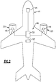
- Figure 2 schematically illustrates an aircraft 44 including at least one gas turbine engine 20.
- the aircraft 44 includes two gas turbine engines 20. It should be understood that this disclosure extends to aircraft having any number of gas turbine engines. Further, while a particular gas turbine engine 20 is illustrated in Figure 1 , it should be understood that this disclosure extends to all types of gas turbine engines.
- the gas turbine engines 20 are in communication with a control unit 46, which is configured to provide commands to the gas turbine engines 20 to control their operation.
- the control unit 46 is configured to initiate an automated takeoff procedure that requires minimal, or no, pilot input.
- the aircraft 44 and gas turbine engines 20, together with the control unit 46, provide an example takeoff power management system.
- control unit 46 refers to any controller on the aircraft 44 configured to control operation of the gas turbine engines 20, including, as examples, an Electronic Engine Controller (EEC) 48 and a Full Authority Digital Engine Control (FADEC) 50.
- EEC Electronic Engine Controller
- FADEC Full Authority Digital Engine Control
- the control unit 46 includes electronics, software, or both, to perform the necessary control functions for operating the gas turbine engines 20.
- the control unit 46 is shown as multiple devices in Figure 2 , the control unit 46 may be provided by a single device, or by multiple software controllers within one or more hardware devices.
- control unit 46 is electrically coupled to a plurality of areas of the aircraft 44, including a braking system 52 and a cockpit 54 of the aircraft 44.
- the control unit 46 is configured to receive information from the braking system 52 including signals indicating whether the brakes are applied or have been released.
- the control unit 46 is further configured to send signals to the cockpit 54 to inform the pilot(s) of the various operating conditions of the aircraft 44, including the operating conditions of the gas turbine engines 20.
- the gas turbine engines 20 are powered to full power, which is sometimes referred to as takeoff power or N1.
- the control unit 46 is configured to initiate one of an unrestricted takeoff procedure or a rolling takeoff procedure by sending corresponding signals to the gas turbine engines 20.
- an "unrestricted" takeoff procedure refers to any modification to a rolling takeoff procedure, including a static takeoff procedure.
- the control unit 46 is configured to synchronize and coordinate operation of the engines 20 (in examples where the aircraft 44 has more than one engine 20) to prevent thrust asymmetry from one engine being allowed to perform an unrestricted takeoff and the other a rolling takeoff.
- a static takeoff procedure (which, again, is one type of "unrestricted” takeoff procedure)
- the aircraft 44 is held stationary at the end of a runway by the braking system 52, for example, while the gas turbine engines 20 are powered to full power. Once the gas turbine engines 20 reach full power, the brakes of the aircraft 44 are released and the aircraft 44 is allowed to accelerate down the runway.
- a static takeoff procedure may be beneficial in instances where there is a short runway, and is also useful to confirm that the gas turbine engines 20 are capable of reaching full power prior to releasing the brakes.
- the aircraft 44 is allowed to accelerate down the runway while the gas turbine engines 20 are running at an intermediate power, which is less than full power.
- the intermediate power is 60% of full power.
- the gas turbine engines 20 are then run at full power to allow the aircraft 44 to take off.
- Rolling takeoffs may be beneficial because they result in a lower overall takeoff time, and they provide additional passenger comfort because of the smoother acceleration.
- Some gas turbine engines are rated and provided with an operational envelope limiting the conditions in which a static takeoff procedure is recommended.
- a static takeoff is not desired because of the increased likelihood that non-uniform air flow will enter the gas turbine engines 20.
- Non-uniform air flow can cause excessive stress and/or damage to the blades of the fan 42.
- attempting a static takeoff in such conditions may even cause an engine surge.
- ground wind speed is one example condition, other conditions come within the scope of this disclosure, including ground head wind speeds, ground tail wind speeds, temperature, barometric pressure, weather, etc.
- Figure 3 illustrates an example takeoff method 56 that avoids the potential negative impacts associated with performing a static takeoff procedure outside of a rated operational envelope.
- the control unit 46 detects whether the information required to determine whether a static takeoff procedure can be performed is available to the control unit, at 60.
- Example information includes a ground wind speed, such as a cross-wind speed.
- a rolling takeoff is initiated. Before initiating a rolling takeoff, the control unit 46 delivers a message to the cockpit 54 indicating that a rolling takeoff is going to be initiated.
- the aircraft 44 does not include any sensors that report ground wind speed directly to the control unit 46, and the information relating to ground wind speed is not otherwise available to the control unit 46.
- the aircraft 44 did include ground wind speed sensors, that information may still not be available directly to the control unit 46. For instance, that information could be delivered only to the pilot.
- the sensors while present, may be experiencing a temporary outage and are not detecting or reporting ground wind speed to the control unit 46. In any of these instances, the control unit 46 would initiate the rolling takeoff procedure, at 62.
- ground wind speed may be known to the pilot or air traffic controller, for example, this disclosure reduces pilot workload.
- the pilot does not need to monitor wind speed during a takeoff procedure, nor does the pilot need to make an independent judgment regarding whether to initiate a static or a rolling takeoff procedure. Rather, the control unit 46 makes that judgment based on the information, or lack thereof, provided directly to the control unit 46.
- the control unit 46 would determine whether the ground wind speed exceeded a predetermined threshold, at 64.
- the predetermined threshold is defined by the rated operational envelope of the engine, and is unique to the particular model of gas turbine engine 20.
- the predetermined threshold corresponds to a ground wind speed that may increase the likelihood of non-uniform air flow entering the gas turbine engine 20 during a static takeoff.
- the predetermined threshold is 20 knots (about 10.3 m/s).
- a rolling takeoff would be initiated, at 62. If not, the control unit would initiate a static takeoff, at 66. In either case, the control unit 46 would deliver a message to the cockpit 54 indicating the type of takeoff procedure that is going to be initiated.
- the control unit 46 When a rolling takeoff is initiated, the control unit 46, at 68, is configured to accelerate the aircraft 44 while running the gas turbine engines at an intermediate power for a period of time.
- the intermediate power in one example, is 60% of full power.
- the aircraft 44 is allowed to run at the intermediate power to allow the ground speed of the aircraft 44 to reach a predetermined ground speed, at 70.
- the control unit 46 commands the gas turbine engines 20 to run at full power, at 72, to allow for takeoff.
- the predetermined ground speed may be selected to correspond to a speed where the likelihood of non-uniform air flow entering the gas turbine engines 20 is relatively minimal. In a further example, the predetermined ground speed may be selected to correspond to a speed where the likelihood of non-uniform air flow entering the gas turbine engines is substantially zero.
- the predetermined ground speed in one example, is 60 knots (about 30.9 m/s).
- the ground speed of the aircraft 44 is not readily available to the control unit 46.
- the ground speed of the aircraft 44 can be calculated by the control unit 46 by integrating the acceleration the aircraft 44 relative to time.
- the time is known, in one example, as a time from the release of the braking system 52, or a time from an initiation of the rolling takeoff command.
- Aircraft ground speed can be determined in other ways, however, such as through a global positioning system (GPS).
- GPS global positioning system
- this disclosure reduces pilot workload during takeoff.
- pilots are not required to monitor conditions, such as ground wind speed, etc., during takeoff.
- the pilot is not required to make an independent judgment as to the type of takeoff procedure that is performed.
- static takeoffs may be beneficial in some instances, this disclosure essentially defaults to rolling takeoffs in the absence of necessary information being provided to the control unit. Therefore, this disclosure reduces errors in independent pilot judgment, and otherwise protects the gas turbine engines from damage due to a static takeoff procedure being initiated outside of an engine's rated operational envelope.
Landscapes
- Engineering & Computer Science (AREA)
- Aviation & Aerospace Engineering (AREA)
- Chemical & Material Sciences (AREA)
- Combustion & Propulsion (AREA)
- Mechanical Engineering (AREA)
- General Engineering & Computer Science (AREA)
- Radar, Positioning & Navigation (AREA)
- Remote Sensing (AREA)
- Physics & Mathematics (AREA)
- General Physics & Mathematics (AREA)
- Automation & Control Theory (AREA)
- Wind Motors (AREA)
- Control Of Turbines (AREA)
Abstract
Description
- This disclosure relates to a takeoff power management system and method for a gas turbine engine.
- Gas turbine engines typically include a compressor section, a combustor section, and a turbine section. In general, during operation, air is pressurized in the compressor section and is mixed with fuel and burned in the combustor section to generate hot combustion gases. The hot combustion gases flow through the turbine section, which extracts energy from the hot combustion gases to power the compressor section and other gas turbine engine loads.
- In order to initiate takeoff of an aircraft, gas turbine engines are powered to full power, which is sometimes referred to as takeoff power. In one known takeoff procedure, known as a static takeoff procedure (which is a type of "unrestricted" takeoff procedure), the aircraft is held stationary at the end of a runway while the gas turbine engines are powered to full power. Once the gas turbine engines reach full power, the brakes of the aircraft are released and the aircraft is allowed to accelerate down the runway.
- Another type of takeoff procedure is known as a rolling takeoff procedure. In a rolling takeoff procedure, the aircraft is allowed to accelerate down the runway while the gas turbine engines are run at an intermediate power. After accelerating at intermediate power for a period of time, the gas turbine engines are run at full power.
- In some known systems, the pilot has the discretion to initiate a particular takeoff procedure. Various factors, such as runway length, may determine whether a static takeoff or a rolling takeoff is desirable. However, some gas turbine engines are rated for static takeoffs only during certain operating conditions. If an operating condition, such as ground wind speed, exceeds a predetermined threshold value, a static takeoff is not recommended. Information relating to ground wind speed is typically checked by the pilot prior to takeoff, and the pilot initiates a particular takeoff procedure based on the ground wind speed value and corresponding rating of the gas turbine engine.
- A gas turbine engine according to an exemplary aspect of the present invention includes, among other things, a control unit to command the gas turbine engine to perform one of a rolling takeoff procedure and an unrestricted takeoff procedure. The control unit is configured command the gas turbine engine to perform the rolling takeoff procedure when information required to determine whether the unrestricted takeoff procedure can be performed is unavailable to the control unit.
- In a further non-limiting embodiment of the foregoing engine, when the information is available to the control unit, the control unit is configured to initiate the rolling takeoff procedure if the information exceeds a predetermined threshold value.
- In a further non-limiting embodiment of either of the foregoing engines, the information includes a ground wind speed.
- In a further non-limiting embodiment of any of the foregoing engines, the ground wind speed is a cross-wind speed.
- In a further non-limiting embodiment of any of the foregoing engines, following initiation of the rolling takeoff procedure, the control unit is configured to power the gas turbine engine to full power after running at intermediate power for a period of time.
- In a further non-limiting embodiment of any of the foregoing engines, the period of time includes a period of time to allow the ground speed of an aircraft to reach a predetermined ground speed.
- In a further non-limiting embodiment of any of the foregoing engines, the control unit is configured to determine the ground speed by integrating the acceleration of the aircraft relative to the time since initiation of the rolling takeoff procedure.
- In a further non-limiting embodiment of any of the foregoing engines, the initiation of the rolling takeoff procedure is indicated by a release of a brake of the aircraft.
- In a further non-limiting embodiment of any of the foregoing engines, the unrestricted takeoff procedure is a static takeoff procedure and includes powering the gas turbine engine to full power before accelerating an aircraft.
- In a further non-limiting embodiment of any of the foregoing engines, the rolling takeoff procedure includes accelerating the aircraft while running the gas turbine engine at an intermediate power for a period of time before running the gas turbine engine at full power.
- In a further non-limiting embodiment of any of the foregoing engines, full power is a level of power capable of allowing the aircraft to takeoff.
- This aspect of the present invention extends to an aircraft comprising a gas turbine engine as described above and in relation to any embodiment thereof.
- A method according to an exemplary aspect of the present invention includes, among other things, initiating a rolling takeoff procedure when information required to determine whether an unrestricted takeoff procedure can be performed is unavailable to a control unit.
- In a further non-limiting embodiment of the foregoing method, the method includes initiating a rolling takeoff procedure when the information is available to the control unit and the information exceeds a predetermined threshold value.
- In a further non-limiting embodiment of either of the foregoing methods, the information required to determine whether the unrestricted takeoff procedure can be performed includes a ground wind speed.
- In a further non-limiting embodiment of any of the foregoing methods, the rolling takeoff procedure comprises accelerating an aircraft by running a gas turbine engine at an intermediate power for a period of time, and accelerating the aircraft by running the gas turbine engine at full power after the period of time.
- In a further non-limiting embodiment of any of the foregoing methods, the period of time is a time to allow the aircraft to reach a predetermined ground speed.
- In a further non-limiting embodiment of any of the foregoing methods, the unrestricted takeoff procedure is a static takeoff procedure.
- In a further non-limiting embodiment of any of the foregoing methods, the method includes coordinating operation of a plurality of gas turbine engines to prevent thrust asymmetry.
- The embodiments, examples and alternatives of the preceding paragraphs, the claims, or the following description and drawings, including any of their various aspects or respective individual features, may be taken independently or in any combination. Features described in connection with one embodiment are applicable to all embodiments, unless such features are incompatible.
- The drawings can be briefly described as follows:
-
Figure 1 illustrates a schematic, cross-sectional view of a gas turbine engine. -
Figure 2 schematically illustrates an example aircraft. -
Figure 3 is a flow chart representative of an example takeoff method. -
Figure 1 schematically illustrates agas turbine engine 20. Thegas turbine engine 20 is disclosed herein as a two-spool turbofan that generally incorporates afan section 22, acompressor section 24, acombustor section 26, and aturbine section 28. Thefan section 22 drives air along a bypass flow path B in a bypass duct defined within afan case 15 and located radially outward from a core engine case 17. Thecompressor section 24 drives air along a core flow path C for compression and communication into thecombustor section 26, and then expansion through theturbine section 28. - The exemplary
gas turbine engine 20 generally includes alow speed spool 30 and ahigh speed spool 32 mounted for rotation about an engine central longitudinal axis A relative to an engine static structure 36 viaseveral bearing systems 38. Thelow speed spool 30 is in communication with aspeed change mechanism 40, such as an epicyclic gear train, that allows afan 42 on thefan section 22 to rotate at a lower speed than thelow speed spool 30. -
Figure 2 schematically illustrates an aircraft 44 including at least onegas turbine engine 20. In the example ofFigure 2 , the aircraft 44 includes twogas turbine engines 20. It should be understood that this disclosure extends to aircraft having any number of gas turbine engines. Further, while a particulargas turbine engine 20 is illustrated inFigure 1 , it should be understood that this disclosure extends to all types of gas turbine engines. - As shown in
Figure 2 , thegas turbine engines 20 are in communication with acontrol unit 46, which is configured to provide commands to thegas turbine engines 20 to control their operation. In particular, thecontrol unit 46 is configured to initiate an automated takeoff procedure that requires minimal, or no, pilot input. The aircraft 44 andgas turbine engines 20, together with thecontrol unit 46, provide an example takeoff power management system. - In this disclosure, reference to the
control unit 46 refers to any controller on the aircraft 44 configured to control operation of thegas turbine engines 20, including, as examples, an Electronic Engine Controller (EEC) 48 and a Full Authority Digital Engine Control (FADEC) 50. Thecontrol unit 46 includes electronics, software, or both, to perform the necessary control functions for operating thegas turbine engines 20. Although thecontrol unit 46 is shown as multiple devices inFigure 2 , thecontrol unit 46 may be provided by a single device, or by multiple software controllers within one or more hardware devices. - In
Figure 2 , thecontrol unit 46 is electrically coupled to a plurality of areas of the aircraft 44, including abraking system 52 and acockpit 54 of the aircraft 44. Thecontrol unit 46 is configured to receive information from thebraking system 52 including signals indicating whether the brakes are applied or have been released. Thecontrol unit 46 is further configured to send signals to thecockpit 54 to inform the pilot(s) of the various operating conditions of the aircraft 44, including the operating conditions of thegas turbine engines 20. - In order for the aircraft 44 to take off, the
gas turbine engines 20 are powered to full power, which is sometimes referred to as takeoff power or N1. In one example, thecontrol unit 46 is configured to initiate one of an unrestricted takeoff procedure or a rolling takeoff procedure by sending corresponding signals to thegas turbine engines 20. In this disclosure an "unrestricted" takeoff procedure refers to any modification to a rolling takeoff procedure, including a static takeoff procedure. Further, thecontrol unit 46 is configured to synchronize and coordinate operation of the engines 20 (in examples where the aircraft 44 has more than one engine 20) to prevent thrust asymmetry from one engine being allowed to perform an unrestricted takeoff and the other a rolling takeoff. - In a static takeoff procedure (which, again, is one type of "unrestricted" takeoff procedure), the aircraft 44 is held stationary at the end of a runway by the
braking system 52, for example, while thegas turbine engines 20 are powered to full power. Once thegas turbine engines 20 reach full power, the brakes of the aircraft 44 are released and the aircraft 44 is allowed to accelerate down the runway. A static takeoff procedure may be beneficial in instances where there is a short runway, and is also useful to confirm that thegas turbine engines 20 are capable of reaching full power prior to releasing the brakes. - In a rolling takeoff procedure, the aircraft 44 is allowed to accelerate down the runway while the
gas turbine engines 20 are running at an intermediate power, which is less than full power. In one example, the intermediate power is 60% of full power. After accelerating at intermediate power for a period of time, thegas turbine engines 20 are then run at full power to allow the aircraft 44 to take off. Rolling takeoffs may be beneficial because they result in a lower overall takeoff time, and they provide additional passenger comfort because of the smoother acceleration. - Some gas turbine engines are rated and provided with an operational envelope limiting the conditions in which a static takeoff procedure is recommended. In some conditions, such as a high ground wind speed, or a high ground cross-wind, a static takeoff is not desired because of the increased likelihood that non-uniform air flow will enter the
gas turbine engines 20. Non-uniform air flow can cause excessive stress and/or damage to the blades of thefan 42. Further, in some cases, attempting a static takeoff in such conditions may even cause an engine surge. While ground wind speed is one example condition, other conditions come within the scope of this disclosure, including ground head wind speeds, ground tail wind speeds, temperature, barometric pressure, weather, etc. -
Figure 3 illustrates an example takeoff method 56 that avoids the potential negative impacts associated with performing a static takeoff procedure outside of a rated operational envelope. In the method 56, when initiating a takeoff, at 58, thecontrol unit 46 detects whether the information required to determine whether a static takeoff procedure can be performed is available to the control unit, at 60. Example information includes a ground wind speed, such as a cross-wind speed. - If ground wind speed information, for example, is unavailable to the
control unit 46, then thecontrol unit 46 itself cannot make a determination of whether to allow a static takeoff. Thus, at 62, a rolling takeoff is initiated. Before initiating a rolling takeoff, thecontrol unit 46 delivers a message to thecockpit 54 indicating that a rolling takeoff is going to be initiated. - In the example of
Figure 2 , the aircraft 44 does not include any sensors that report ground wind speed directly to thecontrol unit 46, and the information relating to ground wind speed is not otherwise available to thecontrol unit 46. Alternatively, if the aircraft 44 did include ground wind speed sensors, that information may still not be available directly to thecontrol unit 46. For instance, that information could be delivered only to the pilot. In another example, the sensors, while present, may be experiencing a temporary outage and are not detecting or reporting ground wind speed to thecontrol unit 46. In any of these instances, thecontrol unit 46 would initiate the rolling takeoff procedure, at 62. - While ground wind speed may be known to the pilot or air traffic controller, for example, this disclosure reduces pilot workload. In this disclosure, the pilot does not need to monitor wind speed during a takeoff procedure, nor does the pilot need to make an independent judgment regarding whether to initiate a static or a rolling takeoff procedure. Rather, the
control unit 46 makes that judgment based on the information, or lack thereof, provided directly to thecontrol unit 46. - If the aircraft 44 had included sensors for determining ground wind speed, for example, the
control unit 46 would determine whether the ground wind speed exceeded a predetermined threshold, at 64. The predetermined threshold is defined by the rated operational envelope of the engine, and is unique to the particular model ofgas turbine engine 20. The predetermined threshold corresponds to a ground wind speed that may increase the likelihood of non-uniform air flow entering thegas turbine engine 20 during a static takeoff. In one example, the predetermined threshold is 20 knots (about 10.3 m/s). - If the predetermined value is exceeded, a rolling takeoff would be initiated, at 62. If not, the control unit would initiate a static takeoff, at 66. In either case, the
control unit 46 would deliver a message to thecockpit 54 indicating the type of takeoff procedure that is going to be initiated. - When a rolling takeoff is initiated, the
control unit 46, at 68, is configured to accelerate the aircraft 44 while running the gas turbine engines at an intermediate power for a period of time. The intermediate power, in one example, is 60% of full power. The aircraft 44 is allowed to run at the intermediate power to allow the ground speed of the aircraft 44 to reach a predetermined ground speed, at 70. Once the aircraft 44 has reached the predetermined ground speed, thecontrol unit 46 commands thegas turbine engines 20 to run at full power, at 72, to allow for takeoff. - The predetermined ground speed may be selected to correspond to a speed where the likelihood of non-uniform air flow entering the
gas turbine engines 20 is relatively minimal. In a further example, the predetermined ground speed may be selected to correspond to a speed where the likelihood of non-uniform air flow entering the gas turbine engines is substantially zero. The predetermined ground speed, in one example, is 60 knots (about 30.9 m/s). - In some examples, the ground speed of the aircraft 44 is not readily available to the
control unit 46. In those examples, the ground speed of the aircraft 44 can be calculated by thecontrol unit 46 by integrating the acceleration the aircraft 44 relative to time. The time is known, in one example, as a time from the release of thebraking system 52, or a time from an initiation of the rolling takeoff command. Aircraft ground speed can be determined in other ways, however, such as through a global positioning system (GPS). - Again, this disclosure reduces pilot workload during takeoff. With this disclosure, pilots are not required to monitor conditions, such as ground wind speed, etc., during takeoff. Thus, the pilot is not required to make an independent judgment as to the type of takeoff procedure that is performed. Further, while static takeoffs may be beneficial in some instances, this disclosure essentially defaults to rolling takeoffs in the absence of necessary information being provided to the control unit. Therefore, this disclosure reduces errors in independent pilot judgment, and otherwise protects the gas turbine engines from damage due to a static takeoff procedure being initiated outside of an engine's rated operational envelope.
- Although the different examples have the specific components shown in the illustrations, embodiments of this disclosure are not limited to those particular combinations. It is possible to use some of the components or features from one of the examples in combination with features or components from another one of the examples.
- One of ordinary skill in this art would understand that the above-described embodiments are exemplary and non-limiting. That is, modifications of this disclosure would come within the scope of the claims. Accordingly, the following claims should be studied to determine their true scope and content.
Claims (15)
- A gas turbine engine (20), comprising:a control unit (46) to command the gas turbine engine to perform one of a rolling takeoff procedure and an unrestricted takeoff procedure, wherein the control unit (46) is configured to command the gas turbine engine to perform the rolling takeoff procedure when information required to determine whether the unrestricted takeoff procedure can be performed is unavailable to the control unit (46).
- The gas turbine engine as recited in claim 1, wherein, when the information is available to the control unit (46), the control unit (46) is configured to initiate the rolling takeoff procedure if the information exceeds a predetermined threshold value.
- The gas turbine engine as recited in claim 1 or 2, wherein the information includes a ground wind speed.
- The gas turbine engine as recited in claim 3, wherein the ground wind speed is a cross-wind speed.
- The gas turbine engine as recited in any preceding claim, wherein, following initiation of the rolling takeoff procedure, the control unit (46) is configured to power the gas turbine engine to full power after running at intermediate power for a period of time.
- The gas turbine engine as recited in claim 5, wherein the period of time includes a period of time to allow the ground speed of an aircraft (44) to reach a predetermined ground speed.
- The gas turbine engine as recited in claim 6, wherein the control unit (46) is configured to determine the ground speed by integrating the acceleration of the aircraft (44) relative to the time since initiation of the rolling takeoff procedure,
wherein, optionally, the initiation of the rolling takeoff procedure is indicated by a release of a brake (52) of the aircraft (44). - The gas turbine engine as recited in any preceding claim, wherein the unrestricted takeoff procedure is a static takeoff procedure and includes powering the gas turbine engine to full power before accelerating an aircraft (44).
- The gas turbine engine as recited in any preceding claim, wherein the rolling takeoff procedure includes accelerating an aircraft (44) while running the gas turbine engine at an intermediate power for a period of time before running the gas turbine engine at full power,
wherein, optionally, full power is a level of power capable of allowing the aircraft (44) to takeoff. - A method, comprising:initiating a rolling takeoff procedure when information required to determine whether an unrestricted takeoff procedure can be performed is unavailable to a control unit (46).
- The method as recited in claim 10, further comprising initiating a rolling takeoff procedure when the information is available to the control unit (46) and the information exceeds a predetermined threshold value.
- The method as recited in claim 10 or 11, wherein the information required to determine whether the unrestricted takeoff procedure can be performed includes a ground wind speed.
- The method as recited in any of claims 10 to 12, wherein the rolling takeoff procedure comprises:accelerating an aircraft (44) by running a gas turbine engine (20) at an intermediate power for a period of time; andaccelerating the aircraft (44) by running the gas turbine engine (20) at full power after the period of time,wherein, optionally, the period of time is a time to allow the aircraft (44) to reach a predetermined ground speed.
- The method as recited in any of claims 10 to 13, wherein the unrestricted takeoff procedure is a static takeoff procedure.
- The method as recited in any of claims 10 to 14, further comprising coordinating operation of a plurality of gas turbine engines (20) to prevent thrust asymmetry.
Applications Claiming Priority (1)
| Application Number | Priority Date | Filing Date | Title |
|---|---|---|---|
| US15/072,869 US10293951B2 (en) | 2016-03-17 | 2016-03-17 | Takeoff power management system and method for gas turbine engines |
Publications (2)
| Publication Number | Publication Date |
|---|---|
| EP3219965A1 true EP3219965A1 (en) | 2017-09-20 |
| EP3219965B1 EP3219965B1 (en) | 2023-01-25 |
Family
ID=58387628
Family Applications (1)
| Application Number | Title | Priority Date | Filing Date |
|---|---|---|---|
| EP17160897.9A Active EP3219965B1 (en) | 2016-03-17 | 2017-03-14 | Takeoff power management system and method for gas turbine engines |
Country Status (2)
| Country | Link |
|---|---|
| US (1) | US10293951B2 (en) |
| EP (1) | EP3219965B1 (en) |
Families Citing this family (3)
| Publication number | Priority date | Publication date | Assignee | Title |
|---|---|---|---|---|
| CN110799420B (en) * | 2017-06-30 | 2023-07-21 | 加拿大空客有限合伙公司 | Systems and methods for controlling takeoff thrust |
| US11837099B2 (en) | 2019-11-22 | 2023-12-05 | Ge Aviation Systems Limited | Aircraft flight management system |
| US20230166857A1 (en) * | 2021-11-29 | 2023-06-01 | Raytheon Technologies Corporation | Final takeoff speed determination for an aircraft |
Citations (2)
| Publication number | Priority date | Publication date | Assignee | Title |
|---|---|---|---|---|
| US20080029653A1 (en) * | 2006-07-25 | 2008-02-07 | Lockheed Martin Corporation | Control system for controlling propeller aircraft engine during takeoff |
| US20100070112A1 (en) * | 2008-09-17 | 2010-03-18 | Couey Lyle M | Progressive takeoff thrust ramp for an aircraft |
Family Cites Families (13)
| Publication number | Priority date | Publication date | Assignee | Title |
|---|---|---|---|---|
| US4122522A (en) | 1974-05-20 | 1978-10-24 | Smith Gerald R | Aircraft ground monitoring system |
| US4980833A (en) | 1988-07-26 | 1990-12-25 | The University Of Tennessee Research Corporation | Airplane take-off monitor with learning feature |
| US6722610B1 (en) | 2002-11-25 | 2004-04-20 | The Boeing Company | Method, system, and computer program product for controlling maneuverable wheels on a vehicle |
| FR2902408B1 (en) * | 2006-06-19 | 2008-08-08 | Eurocopter France | POWER BALANCING OF TWO TURBOMOTORS OF AN AIRCRAFT |
| US7946165B2 (en) | 2009-05-05 | 2011-05-24 | Goodrich Corporation | Over-speed, rough loads and hard landing detection system |
| US20110040431A1 (en) | 2009-08-11 | 2011-02-17 | Honeywell International Inc. | Automated take off control system and method |
| CN101870363A (en) | 2010-06-17 | 2010-10-27 | 葛泓杉 | Short-distance takeoff aircraft of energy storing type airplane |
| FR2973840B1 (en) * | 2011-04-07 | 2015-09-18 | Airbus Operations Sas | METHOD AND DEVICE FOR CONTROLLING THE REGIME OF ENGINES OF AN AIRCRAFT DURING A TAKE - OFF PHASE. |
| US10315777B2 (en) | 2011-12-22 | 2019-06-11 | Embraer S.A. | Safe takeoff monitoring system |
| US20130327014A1 (en) * | 2012-06-12 | 2013-12-12 | Djamal Moulebhar | Devices and Methods to Optimize Aircraft Power Plant and Aircraft Operations |
| US20140018980A1 (en) * | 2012-07-12 | 2014-01-16 | General Electric Company | Systems and methods for flight management |
| US9156564B2 (en) * | 2013-01-22 | 2015-10-13 | Exhaustless, Inc. | Airport capacity from takeoff assist |
| US9483052B2 (en) * | 2014-06-12 | 2016-11-01 | The Boeing Company | Aircraft departure profile generation compliant with noise abatement limits |
-
2016
- 2016-03-17 US US15/072,869 patent/US10293951B2/en active Active
-
2017
- 2017-03-14 EP EP17160897.9A patent/EP3219965B1/en active Active
Patent Citations (2)
| Publication number | Priority date | Publication date | Assignee | Title |
|---|---|---|---|---|
| US20080029653A1 (en) * | 2006-07-25 | 2008-02-07 | Lockheed Martin Corporation | Control system for controlling propeller aircraft engine during takeoff |
| US20100070112A1 (en) * | 2008-09-17 | 2010-03-18 | Couey Lyle M | Progressive takeoff thrust ramp for an aircraft |
Also Published As
| Publication number | Publication date |
|---|---|
| EP3219965B1 (en) | 2023-01-25 |
| US20170267366A1 (en) | 2017-09-21 |
| US10293951B2 (en) | 2019-05-21 |
Similar Documents
| Publication | Publication Date | Title |
|---|---|---|
| EP3931098B1 (en) | Normal mode operation of hybrid electric propulsion systems | |
| CN110844088B (en) | Fault tolerant hybrid electric propulsion system for aircraft | |
| US11999495B2 (en) | Degraded mode operation of hybrid electric propulsion systems | |
| US11428171B2 (en) | Electric machine assistance for multi-spool turbomachine operation and control | |
| US10309317B2 (en) | Air turbine starter pressure monitor system | |
| EP3927620B1 (en) | Control systems for hybrid electric powerplants | |
| US9346553B2 (en) | Balancing the power of two turboshaft engines of an aircraft | |
| EP2915749B1 (en) | System and method for operating a multi-engine aircraft in an auxiliary power unit mode | |
| US7841163B2 (en) | Turbofan emergency generator | |
| EP3163049B1 (en) | Gas turbine engine with braking system | |
| EP4086446B1 (en) | Hybrid electric idle and braking for an aircraft | |
| US12253030B2 (en) | In-flight engine re-start | |
| CN109305376B (en) | System and method for determining minimum pitch and minimum gas generator idle states | |
| EP3219965B1 (en) | Takeoff power management system and method for gas turbine engines | |
| EP3091198A1 (en) | Thrust reversal for turbofan gas turbine engine | |
| US12387610B2 (en) | Hybrid electric engine power distribution | |
| EP4102044A2 (en) | Hybrid electric engine power distribution | |
| CN104271923A (en) | Turbo machine comprising a monitoring system comprising a module for engaging a protection function of the turbo machine and monitoring method | |
| US10677251B2 (en) | Method and device for testing samples on a turbine engine minimizing the risk of surge by the exchange of information between an energy manager and a system for testing the turbine engine | |
| EP3106649B1 (en) | Aircraft gas turbine propulsion engine control without aircraft total air temperature sensors | |
| US20140178175A1 (en) | Air turbine starter monitor system | |
| US10227933B2 (en) | Aircraft power setting trims for life extension |
Legal Events
| Date | Code | Title | Description |
|---|---|---|---|
| PUAI | Public reference made under article 153(3) epc to a published international application that has entered the european phase |
Free format text: ORIGINAL CODE: 0009012 |
|
| STAA | Information on the status of an ep patent application or granted ep patent |
Free format text: STATUS: THE APPLICATION HAS BEEN PUBLISHED |
|
| AK | Designated contracting states |
Kind code of ref document: A1 Designated state(s): AL AT BE BG CH CY CZ DE DK EE ES FI FR GB GR HR HU IE IS IT LI LT LU LV MC MK MT NL NO PL PT RO RS SE SI SK SM TR |
|
| AX | Request for extension of the european patent |
Extension state: BA ME |
|
| STAA | Information on the status of an ep patent application or granted ep patent |
Free format text: STATUS: REQUEST FOR EXAMINATION WAS MADE |
|
| 17P | Request for examination filed |
Effective date: 20180319 |
|
| RBV | Designated contracting states (corrected) |
Designated state(s): AL AT BE BG CH CY CZ DE DK EE ES FI FR GB GR HR HU IE IS IT LI LT LU LV MC MK MT NL NO PL PT RO RS SE SI SK SM TR |
|
| RAP1 | Party data changed (applicant data changed or rights of an application transferred) |
Owner name: RAYTHEON TECHNOLOGIES CORPORATION |
|
| STAA | Information on the status of an ep patent application or granted ep patent |
Free format text: STATUS: EXAMINATION IS IN PROGRESS |
|
| 17Q | First examination report despatched |
Effective date: 20210324 |
|
| GRAP | Despatch of communication of intention to grant a patent |
Free format text: ORIGINAL CODE: EPIDOSNIGR1 |
|
| STAA | Information on the status of an ep patent application or granted ep patent |
Free format text: STATUS: GRANT OF PATENT IS INTENDED |
|
| INTG | Intention to grant announced |
Effective date: 20221005 |
|
| GRAS | Grant fee paid |
Free format text: ORIGINAL CODE: EPIDOSNIGR3 |
|
| GRAA | (expected) grant |
Free format text: ORIGINAL CODE: 0009210 |
|
| STAA | Information on the status of an ep patent application or granted ep patent |
Free format text: STATUS: THE PATENT HAS BEEN GRANTED |
|
| AK | Designated contracting states |
Kind code of ref document: B1 Designated state(s): AL AT BE BG CH CY CZ DE DK EE ES FI FR GB GR HR HU IE IS IT LI LT LU LV MC MK MT NL NO PL PT RO RS SE SI SK SM TR |
|
| REG | Reference to a national code |
Ref country code: GB Ref legal event code: FG4D |
|
| REG | Reference to a national code |
Ref country code: CH Ref legal event code: EP |
|
| REG | Reference to a national code |
Ref country code: AT Ref legal event code: REF Ref document number: 1546067 Country of ref document: AT Kind code of ref document: T Effective date: 20230215 Ref country code: IE Ref legal event code: FG4D |
|
| REG | Reference to a national code |
Ref country code: DE Ref legal event code: R096 Ref document number: 602017065691 Country of ref document: DE |
|
| REG | Reference to a national code |
Ref country code: LT Ref legal event code: MG9D |
|
| REG | Reference to a national code |
Ref country code: NL Ref legal event code: MP Effective date: 20230125 |
|
| REG | Reference to a national code |
Ref country code: AT Ref legal event code: MK05 Ref document number: 1546067 Country of ref document: AT Kind code of ref document: T Effective date: 20230125 |
|
| P01 | Opt-out of the competence of the unified patent court (upc) registered |
Effective date: 20230520 |
|
| PG25 | Lapsed in a contracting state [announced via postgrant information from national office to epo] |
Ref country code: NL Free format text: LAPSE BECAUSE OF FAILURE TO SUBMIT A TRANSLATION OF THE DESCRIPTION OR TO PAY THE FEE WITHIN THE PRESCRIBED TIME-LIMIT Effective date: 20230125 |
|
| PG25 | Lapsed in a contracting state [announced via postgrant information from national office to epo] |
Ref country code: RS Free format text: LAPSE BECAUSE OF FAILURE TO SUBMIT A TRANSLATION OF THE DESCRIPTION OR TO PAY THE FEE WITHIN THE PRESCRIBED TIME-LIMIT Effective date: 20230125 Ref country code: PT Free format text: LAPSE BECAUSE OF FAILURE TO SUBMIT A TRANSLATION OF THE DESCRIPTION OR TO PAY THE FEE WITHIN THE PRESCRIBED TIME-LIMIT Effective date: 20230525 Ref country code: NO Free format text: LAPSE BECAUSE OF FAILURE TO SUBMIT A TRANSLATION OF THE DESCRIPTION OR TO PAY THE FEE WITHIN THE PRESCRIBED TIME-LIMIT Effective date: 20230425 Ref country code: LV Free format text: LAPSE BECAUSE OF FAILURE TO SUBMIT A TRANSLATION OF THE DESCRIPTION OR TO PAY THE FEE WITHIN THE PRESCRIBED TIME-LIMIT Effective date: 20230125 Ref country code: LT Free format text: LAPSE BECAUSE OF FAILURE TO SUBMIT A TRANSLATION OF THE DESCRIPTION OR TO PAY THE FEE WITHIN THE PRESCRIBED TIME-LIMIT Effective date: 20230125 Ref country code: HR Free format text: LAPSE BECAUSE OF FAILURE TO SUBMIT A TRANSLATION OF THE DESCRIPTION OR TO PAY THE FEE WITHIN THE PRESCRIBED TIME-LIMIT Effective date: 20230125 Ref country code: ES Free format text: LAPSE BECAUSE OF FAILURE TO SUBMIT A TRANSLATION OF THE DESCRIPTION OR TO PAY THE FEE WITHIN THE PRESCRIBED TIME-LIMIT Effective date: 20230125 Ref country code: AT Free format text: LAPSE BECAUSE OF FAILURE TO SUBMIT A TRANSLATION OF THE DESCRIPTION OR TO PAY THE FEE WITHIN THE PRESCRIBED TIME-LIMIT Effective date: 20230125 |
|
| PG25 | Lapsed in a contracting state [announced via postgrant information from national office to epo] |
Ref country code: SE Free format text: LAPSE BECAUSE OF FAILURE TO SUBMIT A TRANSLATION OF THE DESCRIPTION OR TO PAY THE FEE WITHIN THE PRESCRIBED TIME-LIMIT Effective date: 20230125 Ref country code: PL Free format text: LAPSE BECAUSE OF FAILURE TO SUBMIT A TRANSLATION OF THE DESCRIPTION OR TO PAY THE FEE WITHIN THE PRESCRIBED TIME-LIMIT Effective date: 20230125 Ref country code: IS Free format text: LAPSE BECAUSE OF FAILURE TO SUBMIT A TRANSLATION OF THE DESCRIPTION OR TO PAY THE FEE WITHIN THE PRESCRIBED TIME-LIMIT Effective date: 20230525 Ref country code: GR Free format text: LAPSE BECAUSE OF FAILURE TO SUBMIT A TRANSLATION OF THE DESCRIPTION OR TO PAY THE FEE WITHIN THE PRESCRIBED TIME-LIMIT Effective date: 20230426 Ref country code: FI Free format text: LAPSE BECAUSE OF FAILURE TO SUBMIT A TRANSLATION OF THE DESCRIPTION OR TO PAY THE FEE WITHIN THE PRESCRIBED TIME-LIMIT Effective date: 20230125 |
|
| REG | Reference to a national code |
Ref country code: DE Ref legal event code: R097 Ref document number: 602017065691 Country of ref document: DE |
|
| PG25 | Lapsed in a contracting state [announced via postgrant information from national office to epo] |
Ref country code: SM Free format text: LAPSE BECAUSE OF FAILURE TO SUBMIT A TRANSLATION OF THE DESCRIPTION OR TO PAY THE FEE WITHIN THE PRESCRIBED TIME-LIMIT Effective date: 20230125 Ref country code: RO Free format text: LAPSE BECAUSE OF FAILURE TO SUBMIT A TRANSLATION OF THE DESCRIPTION OR TO PAY THE FEE WITHIN THE PRESCRIBED TIME-LIMIT Effective date: 20230125 Ref country code: MC Free format text: LAPSE BECAUSE OF FAILURE TO SUBMIT A TRANSLATION OF THE DESCRIPTION OR TO PAY THE FEE WITHIN THE PRESCRIBED TIME-LIMIT Effective date: 20230125 Ref country code: EE Free format text: LAPSE BECAUSE OF FAILURE TO SUBMIT A TRANSLATION OF THE DESCRIPTION OR TO PAY THE FEE WITHIN THE PRESCRIBED TIME-LIMIT Effective date: 20230125 Ref country code: DK Free format text: LAPSE BECAUSE OF FAILURE TO SUBMIT A TRANSLATION OF THE DESCRIPTION OR TO PAY THE FEE WITHIN THE PRESCRIBED TIME-LIMIT Effective date: 20230125 Ref country code: CZ Free format text: LAPSE BECAUSE OF FAILURE TO SUBMIT A TRANSLATION OF THE DESCRIPTION OR TO PAY THE FEE WITHIN THE PRESCRIBED TIME-LIMIT Effective date: 20230125 |
|
| REG | Reference to a national code |
Ref country code: CH Ref legal event code: PL |
|
| RAP4 | Party data changed (patent owner data changed or rights of a patent transferred) |
Owner name: RTX CORPORATION |
|
| PG25 | Lapsed in a contracting state [announced via postgrant information from national office to epo] |
Ref country code: SK Free format text: LAPSE BECAUSE OF FAILURE TO SUBMIT A TRANSLATION OF THE DESCRIPTION OR TO PAY THE FEE WITHIN THE PRESCRIBED TIME-LIMIT Effective date: 20230125 Ref country code: AL Free format text: LAPSE BECAUSE OF FAILURE TO SUBMIT A TRANSLATION OF THE DESCRIPTION OR TO PAY THE FEE WITHIN THE PRESCRIBED TIME-LIMIT Effective date: 20230125 |
|
| REG | Reference to a national code |
Ref country code: BE Ref legal event code: MM Effective date: 20230331 |
|
| PLBE | No opposition filed within time limit |
Free format text: ORIGINAL CODE: 0009261 |
|
| STAA | Information on the status of an ep patent application or granted ep patent |
Free format text: STATUS: NO OPPOSITION FILED WITHIN TIME LIMIT |
|
| PG25 | Lapsed in a contracting state [announced via postgrant information from national office to epo] |
Ref country code: LU Free format text: LAPSE BECAUSE OF NON-PAYMENT OF DUE FEES Effective date: 20230314 |
|
| 26N | No opposition filed |
Effective date: 20231026 |
|
| REG | Reference to a national code |
Ref country code: IE Ref legal event code: MM4A |
|
| PG25 | Lapsed in a contracting state [announced via postgrant information from national office to epo] |
Ref country code: SI Free format text: LAPSE BECAUSE OF FAILURE TO SUBMIT A TRANSLATION OF THE DESCRIPTION OR TO PAY THE FEE WITHIN THE PRESCRIBED TIME-LIMIT Effective date: 20230125 Ref country code: LI Free format text: LAPSE BECAUSE OF NON-PAYMENT OF DUE FEES Effective date: 20230331 Ref country code: IE Free format text: LAPSE BECAUSE OF NON-PAYMENT OF DUE FEES Effective date: 20230314 Ref country code: CH Free format text: LAPSE BECAUSE OF NON-PAYMENT OF DUE FEES Effective date: 20230331 |
|
| PG25 | Lapsed in a contracting state [announced via postgrant information from national office to epo] |
Ref country code: BE Free format text: LAPSE BECAUSE OF NON-PAYMENT OF DUE FEES Effective date: 20230331 |
|
| PG25 | Lapsed in a contracting state [announced via postgrant information from national office to epo] |
Ref country code: IT Free format text: LAPSE BECAUSE OF FAILURE TO SUBMIT A TRANSLATION OF THE DESCRIPTION OR TO PAY THE FEE WITHIN THE PRESCRIBED TIME-LIMIT Effective date: 20230125 |
|
| PG25 | Lapsed in a contracting state [announced via postgrant information from national office to epo] |
Ref country code: BG Free format text: LAPSE BECAUSE OF FAILURE TO SUBMIT A TRANSLATION OF THE DESCRIPTION OR TO PAY THE FEE WITHIN THE PRESCRIBED TIME-LIMIT Effective date: 20230125 |
|
| PG25 | Lapsed in a contracting state [announced via postgrant information from national office to epo] |
Ref country code: BG Free format text: LAPSE BECAUSE OF FAILURE TO SUBMIT A TRANSLATION OF THE DESCRIPTION OR TO PAY THE FEE WITHIN THE PRESCRIBED TIME-LIMIT Effective date: 20230125 |
|
| PG25 | Lapsed in a contracting state [announced via postgrant information from national office to epo] |
Ref country code: CY Free format text: LAPSE BECAUSE OF FAILURE TO SUBMIT A TRANSLATION OF THE DESCRIPTION OR TO PAY THE FEE WITHIN THE PRESCRIBED TIME-LIMIT; INVALID AB INITIO Effective date: 20170314 |
|
| PG25 | Lapsed in a contracting state [announced via postgrant information from national office to epo] |
Ref country code: HU Free format text: LAPSE BECAUSE OF FAILURE TO SUBMIT A TRANSLATION OF THE DESCRIPTION OR TO PAY THE FEE WITHIN THE PRESCRIBED TIME-LIMIT; INVALID AB INITIO Effective date: 20170314 |
|
| REG | Reference to a national code |
Ref country code: DE Ref legal event code: R081 Ref document number: 602017065691 Country of ref document: DE Owner name: RTX CORPORATION (N.D.GES.D. STAATES DELAWARE),, US Free format text: FORMER OWNER: RAYTHEON TECHNOLOGIES CORPORATION, FARMINGTON, CT, US |
|
| PG25 | Lapsed in a contracting state [announced via postgrant information from national office to epo] |
Ref country code: TR Free format text: LAPSE BECAUSE OF FAILURE TO SUBMIT A TRANSLATION OF THE DESCRIPTION OR TO PAY THE FEE WITHIN THE PRESCRIBED TIME-LIMIT Effective date: 20230125 |
|
| PGFP | Annual fee paid to national office [announced via postgrant information from national office to epo] |
Ref country code: GB Payment date: 20260219 Year of fee payment: 10 |
|
| PGFP | Annual fee paid to national office [announced via postgrant information from national office to epo] |
Ref country code: DE Payment date: 20260219 Year of fee payment: 10 |
|
| PGFP | Annual fee paid to national office [announced via postgrant information from national office to epo] |
Ref country code: FR Payment date: 20260219 Year of fee payment: 10 |