EP3219923A1 - Seal anti-rotation feature - Google Patents
Seal anti-rotation feature Download PDFInfo
- Publication number
- EP3219923A1 EP3219923A1 EP17160060.4A EP17160060A EP3219923A1 EP 3219923 A1 EP3219923 A1 EP 3219923A1 EP 17160060 A EP17160060 A EP 17160060A EP 3219923 A1 EP3219923 A1 EP 3219923A1
- Authority
- EP
- European Patent Office
- Prior art keywords
- seal
- arc segment
- carriage
- rib
- seal arc
- Prior art date
- Legal status (The legal status is an assumption and is not a legal conclusion. Google has not performed a legal analysis and makes no representation as to the accuracy of the status listed.)
- Granted
Links
Images



Classifications
-
- F—MECHANICAL ENGINEERING; LIGHTING; HEATING; WEAPONS; BLASTING
- F01—MACHINES OR ENGINES IN GENERAL; ENGINE PLANTS IN GENERAL; STEAM ENGINES
- F01D—NON-POSITIVE DISPLACEMENT MACHINES OR ENGINES, e.g. STEAM TURBINES
- F01D11/00—Preventing or minimising internal leakage of working-fluid, e.g. between stages
- F01D11/08—Preventing or minimising internal leakage of working-fluid, e.g. between stages for sealing space between rotor blade tips and stator
-
- F—MECHANICAL ENGINEERING; LIGHTING; HEATING; WEAPONS; BLASTING
- F01—MACHINES OR ENGINES IN GENERAL; ENGINE PLANTS IN GENERAL; STEAM ENGINES
- F01D—NON-POSITIVE DISPLACEMENT MACHINES OR ENGINES, e.g. STEAM TURBINES
- F01D11/00—Preventing or minimising internal leakage of working-fluid, e.g. between stages
- F01D11/08—Preventing or minimising internal leakage of working-fluid, e.g. between stages for sealing space between rotor blade tips and stator
- F01D11/12—Preventing or minimising internal leakage of working-fluid, e.g. between stages for sealing space between rotor blade tips and stator using a rubstrip, e.g. erodible. deformable or resiliently-biased part
-
- F—MECHANICAL ENGINEERING; LIGHTING; HEATING; WEAPONS; BLASTING
- F01—MACHINES OR ENGINES IN GENERAL; ENGINE PLANTS IN GENERAL; STEAM ENGINES
- F01D—NON-POSITIVE DISPLACEMENT MACHINES OR ENGINES, e.g. STEAM TURBINES
- F01D11/00—Preventing or minimising internal leakage of working-fluid, e.g. between stages
- F01D11/08—Preventing or minimising internal leakage of working-fluid, e.g. between stages for sealing space between rotor blade tips and stator
- F01D11/12—Preventing or minimising internal leakage of working-fluid, e.g. between stages for sealing space between rotor blade tips and stator using a rubstrip, e.g. erodible. deformable or resiliently-biased part
- F01D11/122—Preventing or minimising internal leakage of working-fluid, e.g. between stages for sealing space between rotor blade tips and stator using a rubstrip, e.g. erodible. deformable or resiliently-biased part with erodable or abradable material
-
- F—MECHANICAL ENGINEERING; LIGHTING; HEATING; WEAPONS; BLASTING
- F01—MACHINES OR ENGINES IN GENERAL; ENGINE PLANTS IN GENERAL; STEAM ENGINES
- F01D—NON-POSITIVE DISPLACEMENT MACHINES OR ENGINES, e.g. STEAM TURBINES
- F01D25/00—Component parts, details, or accessories, not provided for in, or of interest apart from, other groups
- F01D25/24—Casings; Casing parts, e.g. diaphragms, casing fastenings
- F01D25/246—Fastening of diaphragms or stator-rings
-
- F—MECHANICAL ENGINEERING; LIGHTING; HEATING; WEAPONS; BLASTING
- F01—MACHINES OR ENGINES IN GENERAL; ENGINE PLANTS IN GENERAL; STEAM ENGINES
- F01D—NON-POSITIVE DISPLACEMENT MACHINES OR ENGINES, e.g. STEAM TURBINES
- F01D5/00—Blades; Blade-carrying members; Heating, heat-insulating, cooling or antivibration means on the blades or the members
- F01D5/12—Blades
- F01D5/28—Selecting particular materials; Particular measures relating thereto; Measures against erosion or corrosion
- F01D5/284—Selection of ceramic materials
-
- F—MECHANICAL ENGINEERING; LIGHTING; HEATING; WEAPONS; BLASTING
- F01—MACHINES OR ENGINES IN GENERAL; ENGINE PLANTS IN GENERAL; STEAM ENGINES
- F01D—NON-POSITIVE DISPLACEMENT MACHINES OR ENGINES, e.g. STEAM TURBINES
- F01D9/00—Stators
- F01D9/02—Nozzles; Nozzle boxes; Stator blades; Guide conduits, e.g. individual nozzles
- F01D9/04—Nozzles; Nozzle boxes; Stator blades; Guide conduits, e.g. individual nozzles forming ring or sector
-
- F—MECHANICAL ENGINEERING; LIGHTING; HEATING; WEAPONS; BLASTING
- F16—ENGINEERING ELEMENTS AND UNITS; GENERAL MEASURES FOR PRODUCING AND MAINTAINING EFFECTIVE FUNCTIONING OF MACHINES OR INSTALLATIONS; THERMAL INSULATION IN GENERAL
- F16J—PISTONS; CYLINDERS; SEALINGS
- F16J15/00—Sealings
- F16J15/16—Sealings between relatively-moving surfaces
- F16J15/34—Sealings between relatively-moving surfaces with slip-ring pressed against a more or less radial face on one member
- F16J15/3464—Mounting of the seal
-
- F—MECHANICAL ENGINEERING; LIGHTING; HEATING; WEAPONS; BLASTING
- F05—INDEXING SCHEMES RELATING TO ENGINES OR PUMPS IN VARIOUS SUBCLASSES OF CLASSES F01-F04
- F05D—INDEXING SCHEME FOR ASPECTS RELATING TO NON-POSITIVE-DISPLACEMENT MACHINES OR ENGINES, GAS-TURBINES OR JET-PROPULSION PLANTS
- F05D2220/00—Application
- F05D2220/30—Application in turbines
- F05D2220/32—Application in turbines in gas turbines
-
- F—MECHANICAL ENGINEERING; LIGHTING; HEATING; WEAPONS; BLASTING
- F05—INDEXING SCHEMES RELATING TO ENGINES OR PUMPS IN VARIOUS SUBCLASSES OF CLASSES F01-F04
- F05D—INDEXING SCHEME FOR ASPECTS RELATING TO NON-POSITIVE-DISPLACEMENT MACHINES OR ENGINES, GAS-TURBINES OR JET-PROPULSION PLANTS
- F05D2240/00—Components
- F05D2240/10—Stators
- F05D2240/11—Shroud seal segments
-
- F—MECHANICAL ENGINEERING; LIGHTING; HEATING; WEAPONS; BLASTING
- F05—INDEXING SCHEMES RELATING TO ENGINES OR PUMPS IN VARIOUS SUBCLASSES OF CLASSES F01-F04
- F05D—INDEXING SCHEME FOR ASPECTS RELATING TO NON-POSITIVE-DISPLACEMENT MACHINES OR ENGINES, GAS-TURBINES OR JET-PROPULSION PLANTS
- F05D2260/00—Function
- F05D2260/30—Retaining components in desired mutual position
-
- F—MECHANICAL ENGINEERING; LIGHTING; HEATING; WEAPONS; BLASTING
- F05—INDEXING SCHEMES RELATING TO ENGINES OR PUMPS IN VARIOUS SUBCLASSES OF CLASSES F01-F04
- F05D—INDEXING SCHEME FOR ASPECTS RELATING TO NON-POSITIVE-DISPLACEMENT MACHINES OR ENGINES, GAS-TURBINES OR JET-PROPULSION PLANTS
- F05D2300/00—Materials; Properties thereof
- F05D2300/20—Oxide or non-oxide ceramics
- F05D2300/22—Non-oxide ceramics
- F05D2300/226—Carbides
- F05D2300/2261—Carbides of silicon
-
- F—MECHANICAL ENGINEERING; LIGHTING; HEATING; WEAPONS; BLASTING
- F05—INDEXING SCHEMES RELATING TO ENGINES OR PUMPS IN VARIOUS SUBCLASSES OF CLASSES F01-F04
- F05D—INDEXING SCHEME FOR ASPECTS RELATING TO NON-POSITIVE-DISPLACEMENT MACHINES OR ENGINES, GAS-TURBINES OR JET-PROPULSION PLANTS
- F05D2300/00—Materials; Properties thereof
- F05D2300/20—Oxide or non-oxide ceramics
- F05D2300/22—Non-oxide ceramics
- F05D2300/228—Nitrides
- F05D2300/2283—Nitrides of silicon
-
- Y—GENERAL TAGGING OF NEW TECHNOLOGICAL DEVELOPMENTS; GENERAL TAGGING OF CROSS-SECTIONAL TECHNOLOGIES SPANNING OVER SEVERAL SECTIONS OF THE IPC; TECHNICAL SUBJECTS COVERED BY FORMER USPC CROSS-REFERENCE ART COLLECTIONS [XRACs] AND DIGESTS
- Y02—TECHNOLOGIES OR APPLICATIONS FOR MITIGATION OR ADAPTATION AGAINST CLIMATE CHANGE
- Y02T—CLIMATE CHANGE MITIGATION TECHNOLOGIES RELATED TO TRANSPORTATION
- Y02T50/00—Aeronautics or air transport
- Y02T50/60—Efficient propulsion technologies, e.g. for aircraft
Definitions
- a gas turbine engine typically includes at least a compressor section, a combustor section and a turbine section.
- the compressor section pressurizes air into the combustion section where the air is mixed with fuel and ignited to generate an exhaust gas flow.
- the exhaust gas flow expands through the turbine section to drive the compressor section and, if the engine is designed for propulsion, a fan section.
- the turbine section may include multiple stages of rotatable blades and static vanes.
- An annular shroud or blade outer air seal may be provided around the blades in close radial proximity to the tips of the blades to reduce the amount of gas flow that escapes around the blades.
- the shroud typically includes a plurality of arc segments that are circumferentially arranged. The arc segments may be abradable to reduce the radial gap with the tips of the blades.
- a seal assembly includes a seal arc segment that defines first and second seal supports, a carriage that defines first and second support members with the first support member supporting the seal arc segment in a first ramped interface and the second support member supporting the seal arc segment in a second ramped interface such that the seal arc segment is circumferentially moveable with respect to the carriage, and an anti-rotation interface in which the seal arc segment and the carriage are engaged.
- the anti-rotation interface restricts circumferential movement of the seal arc segment.
- the anti-rotation interface comprises a rib and a slot.
- the seal arc segment defines the rib.
- the carriage defines the slot.
- the slot is defined by a key received in a body of the carriage.
- the anti-rotation interface is within the middle circumferential third of the seal arc segment.
- the carriage is disposed substantially radially outward of the at least one seal segment.
- the first carriage support is radially inward of the first seal support and the second carriage support is radially inward of the second seal support.
- the seal arc segment comprises ceramic.
- the first and second carriage supports define the ramped interfaces.
- the rib extends axially, and the circumferential distance from the first seal support to the rib is approximately equal to the circumferential distance from the second seal support to the rib.
- a method of sealing a rotor assembly includes providing a seal arc segment radially outward of a rotor, with respect to the axis of rotation of the rotor, where the seal arc segment defines first and second seal supports.
- the seal arc segment is supported on a carriage that defines first and second support members, the first support member supporting the seal arc segment in a first ramped interface and the second support member supporting the seal arc segment in a second ramped interface such that the seal arc segment is circumferentially moveable with respect to the carriage.
- a rib engages with a slot to restrict circumferential movement of the seal arc segment.
- the seal arc segment defines the rib.
- the carriage defines the slot.
- the slot is defined by a key received in a body of the carriage.
- a blade outer air seal includes a seal body that defines a first support at a first circumferential end, a second support at a second circumferential end, and a mating feature circumferentially spaced from the first circumferential end and second circumferential end.
- the mating feature is configured to prevent circumferential rotation of the seal body.
- the seal arc segment comprises ceramic.
- the mating feature is an axially elongated rib.
- the rib is disposed in a pocket at a radially outer portion of the seal body.
- the seal body is monolithic.
- FIG. 1 schematically illustrates a gas turbine engine 20.
- the gas turbine engine 20 is disclosed herein as a two-spool turbofan that generally incorporates a fan section 22, a compressor section 24, a combustor section 26 and a turbine section 28.
- Alternative engine designs can include an augmentor section (not shown) among other systems or features.
- the fan section 22 drives air along a bypass flow path B in a bypass duct defined within a nacelle 15, while the compressor section 24 drives air along a core flow path C for compression and communication into the combustor section 26 then expansion through the turbine section 28.
- the examples herein are not limited to use with two-spool turbofans and may be applied to other types of turbomachinery, including direct drive engine architectures, three-spool engine architectures, and ground-based turbines.
- the engine 20 generally includes a low speed spool 30 and a high speed spool 32 mounted for rotation about an engine central longitudinal axis A relative to an engine static structure 36 via several bearing systems 38. It should be understood that various bearing systems 38 at various locations may alternatively or additionally be provided, and the location of bearing systems 38 may be varied as appropriate to the application.
- the low speed spool 30 generally includes an inner shaft 40 that interconnects a fan 42, a first (or low) pressure compressor 44 and a first (or low) pressure turbine 46.
- the inner shaft 40 is connected to the fan 42 through a speed change mechanism, which in exemplary gas turbine engine 20 is illustrated as a geared architecture 48, to drive the fan 42 at a lower speed than the low speed spool 30.
- the high speed spool 32 includes an outer shaft 50 that interconnects a second (or high) pressure compressor 52 and a second (or high) pressure turbine 54.
- a combustor 56 is arranged between the high pressure compressor 52 and the high pressure turbine 54.
- a mid-turbine frame 57 of the engine static structure 36 is arranged generally between the high pressure turbine 54 and the low pressure turbine 46.
- the mid-turbine frame 57 further supports the bearing systems 38 in the turbine section 28.
- the inner shaft 40 and the outer shaft 50 are concentric and rotate via bearing systems 38 about the engine central longitudinal axis A, which is collinear with their longitudinal axes.
- the core airflow is compressed by the low pressure compressor 44 then the high pressure compressor 52, mixed and burned with fuel in the combustor 56, then expanded over the high pressure turbine 54 and low pressure turbine 46.
- the mid-turbine frame 57 includes airfoils 59 which are in the core airflow path C.
- the turbines 46, 54 rotationally drive the respective low speed spool 30 and high speed spool 32 in response to the expansion.
- gear system 48 may be located aft of combustor section 26 or even aft of turbine section 28, and fan section 22 may be positioned forward or aft of the location of gear system 48.
- the engine 20 in one example is a high-bypass geared aircraft engine.
- the engine 20 bypass ratio is greater than about six (6), with an example embodiment being greater than about ten (10)
- the geared architecture 48 is an epicyclic gear train, such as a planetary gear system or other gear system, with a gear reduction ratio of greater than about 2.3
- the low pressure turbine 46 has a pressure ratio that is greater than about five.
- the engine 20 bypass ratio is greater than about ten (10:1)
- the fan diameter is significantly larger than that of the low pressure compressor 44
- the low pressure turbine 46 has a pressure ratio that is greater than about five 5:1.
- Low pressure turbine 46 pressure ratio is pressure measured prior to inlet of low pressure turbine 46 as related to the pressure at the outlet of the low pressure turbine 46 prior to an exhaust nozzle.
- the geared architecture 48 may be an epicycle gear train, such as a planetary gear system or other gear system, with a gear reduction ratio of greater than about 2.3:1. It should be understood, however, that the above parameters are only exemplary of one embodiment of a geared architecture engine and that the present invention is applicable to other gas turbine engines, including direct drive turbofans.
- the fan section 22 of the engine 20 is designed for a particular flight condition -- typically cruise at about 0.8 Mach and about 35,000 feet.
- the flight condition of 0.8 Mach and 35,000 ft, with the engine at its best fuel consumption - also known as "bucket cruise Thrust Specific Fuel Consumption ('TSFC')" - is the industry standard parameter of lbm of fuel being burned divided by lbf of thrust the engine produces at that minimum point.
- "Low fan pressure ratio” is the pressure ratio across the fan blade alone, without a Fan Exit Guide Vane (“FEGV”) system.
- the low fan pressure ratio as disclosed herein according to one non-limiting embodiment is less than about 1.45.
- Low corrected fan tip speed is the actual fan tip speed in ft/sec divided by an industry standard temperature correction of [(Tram °R) / (518.7 °R)]0.5.
- the "Low corrected fan tip speed” as disclosed herein according to one non-limiting embodiment is less than about 1150 ft / second.
- FIG. 2 illustrates a partial axial view through a portion of one of the stages of the turbine section 28.
- the turbine section 28 includes an annular blade outer air seal (BOAS) system or assembly 60 (hereafter BOAS 60) that is located radially outwards of a rotor 62 that has a row of rotor blades 64.
- BOAS 60 can alternatively or additionally be adapted for other portions of the engine 20, such as the compressor section 24.
- the BOAS 60 includes a plurality of segments 60a that are circumferentially arranged in an annulus around the central axis A of the engine 20.
- Each of the segments 60a generally includes a seal arc segment 66 that is mounted in a carriage or support 68.
- Each carriage 68 is mounted through one or more connections 69a to a case structure 69b.
- the BOAS 60 is in close radial proximity to the tips of the blades 64, to reduce the amount of gas flow that escapes around the blades 64.
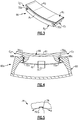
- Figure 3 illustrates an isolated view of a representative one of the seal arc segments 66
- Figure 4 illustrates a sectioned view of a representative one of the segments 60a of the BOAS 60, including the carriage 68 and seal arc segment 66.
- the examples herein may be used to provide compliant, low-stress mounting of the seal arc segment 66 in the carriage 68.
- compliant low-stress mounting may be useful for seal arc segments 66 formed of materials that are sensitive to stress concentrations, although this disclosure is not limited and other types of seals and materials will also benefit.
- the seal arc segments 66 may be monolithic bodies that are formed of a high thermal-resistance, low-toughness material.
- the seal arc segments 66 may be formed of a high thermal-resistance low-toughness metallic alloy or a ceramic-based material, such as a monolithic ceramic or a ceramic matrix composite.
- a high thermal-resistance low-toughness metallic alloy is a molybdenum-based alloy.
- Monolithic ceramics may be, but are not limited to, silicon carbide (SiC) or silicon nitride (Si 3 N 4 ).
- the seal arc segments 66 may be formed of high-toughness material, such as but not limited to metallic alloys.
- Each seal arc segment 66 is a body that defines radially inner and outer sides R1/R2, first and second circumferential ends C1/C2, and first and second axial sides A1/A2.
- the radially inner side R1 faces in a direction toward the engine central axis A.
- the radially inner side R1 is thus the gas path side of the seal arc segment 66 that bounds a portion of the core flow path C.
- the first axial side A1 faces in a forward direction toward the front of the engine 20 (i.e., toward the fan 42), and the second axial side A2 faces in an aft direction toward the rear of the engine 20 (i.e., toward the exhaust end).
- first and second circumferential ends C1/C2 define, respectively, first and second seal supports 70a/70b by which the carriage 68 radially supports or suspends the seal arc segment 66.
- the seal arc segment 66 is thus end-mounted.
- the first and second seal supports 70a/70b have a dovetail geometry.
- the carriage 68 includes first and second support members 68a/68b that serve to radially support the seal arc segment 66 via, respectively, the first and second seal supports 70a/70b.
- the first and second support members 68a/68b are hook supports that interfit with the dovetail geometry of the first and second seal supports 70a/70b.
- the first support member 68a supports the seal arc segment 66 in a first ramped interface 72a and the second support member 68b supports the seal arc segment 66 in a second ramped interface 72b.
- each of the ramped interfaces 72a/72b includes at least one ramped surface on the seal arc segment 66, the carriage 68, or both.
- the surfaces of the first and second seal supports 70a/70b and the surfaces of the first and second support members 68a/68b are ramped.
- the term "ramped" as used herein refers to a support surface that is sloped with respect to both the radial and circumferential directions.
- the carriage 68 is thus substantially radially outward of the seal arc segment 66, except that the supports 68a/68b are radially inward of the supports 70a/70b of the seal arc segment 66.
- the ramped interfaces 72a/72b permit the seal arc segment 66 to move circumferentially with respect to the carriage 68 as the seal arc segment 66 slides up and down the ramped interfaces 72a/72b. Friction in the ramped interfaces 72a/72b during sliding movement can potentially provide damping, and the relatively large contact area across the ramped interfaces 72a/72b distributes loads transferred through the ramped interfaces 72a/72b, which also serves to potentially reduce stress concentrations on the seal arc segment 66.
- an anti-rotation interface 74 is provided between the seal arc segment 66 and the carriage 68 (shown schematically).
- the anti-rotation interface 74 includes a rib or retention post 76 and a slot 78 for receiving the rib 76 to limit circumferential rotation R, as illustrated in Figure 5 .
- the rib 76 may be provided by one of the seal arc segment 66 and the carriage 68, and the slot may be provided by the other of the seal arc segment 66 and the carriage 68.
- the rib 76 is provided by the seal arc segment 66.
- the slot 78 is provided by the carriage 68 (not shown).
- the rib 76 is circumferentially between the supports 70a/70b and extends radially outward from a radially inner surface 79 of a pocket P formed at the radially outer side R2.
- the rib 76 extends a radial distance such that the outer surface of the rib 76 is flush with surrounding edges of the radially outer side R2 of the arc segment 66.
- the rib 76 extends axially, such that when it is received in an axially extending slot 78 of the static carriage 68, the interlocking of the rib 76 and slot 78 limits circumferential rotation of the seal arc segment 66.
- the rib 76 may extend axially from a first circumferentially and radially extending surface PS1 of the pocket P to a second opposite circumferentially and radially extending surface PS2.
- the rib 76 may extend axially across substantially the entire seal arc segment 66.
- Figure 8 illustrates the interface between the rib 76 and the slot 78.
- the slot 78 is provided by an axially and circumferentially extending surface 82, and two opposing radially and axially extending surfaces 86, 88.
- the rib 76 is provided by a circumferentially and axially extending surface 84 and two opposing radially and axially extending surfaces 90, 92.
- the surface 82 of the slot 78 interfaces with the surface 84 of the rib 76.
- the surfaces 86 and 88 of the slot 78 interface with the surfaces 90 and 92 of the rib 76.
- the interfacing between surfaces 86 and 90 limits rotation in a first circumferential direction
- the interface between surfaces 88 and 92 prevents rotation in a second circumferential direction opposite the first circumferential direction.
- the rib 76 is within the middle circumferential third M of the seal arc segment 66 ( Figure 6 ), such that the rib 76 is substantially central to the arc seal segment 66.
- a substantially central rib 76 allows for the thermal growth of the arc seal segment 66 to be centered circumferentially. Additionally, controlling the circumferential position from a central location minimizes the differential radial motion of the seal arc segment on the ramped interfaces 72a/72b, thus minimizing the radial clearance variation between the blade 64 tip and the seal arc segment surface R1.
- the circumferential distance from the first seal support 70a to the rib 76 may be approximately equal to the circumferential distance from the second seal support 70b to the rib 76.
- the carriage may include a carriage body 97 and a key member 96, which provides the slot 78.
- the key member 96 may be a separate member attached to the carriage body 97.
- the key member 96 is placed onto the seal arc segment 66 such that the rib 76 of the seal arc segment 66 is received in the slot 78 of the key member 96.
- the joined seal arc segment 66 and key member 96 are then slid axially into the carriage 68 at an axial end CA1 toward an axial end CA2, such that the key member 96 is slid into an opening or longitudinal slot 98 in the carriage body 97.
- the opening 98 is open in cross-section at an axial end CA1 and extends toward axial end CA2 to receive the axial sliding of the key member 96 joined to the seal arc segment 66.
- the opening 98 may extend radially outward from a radially inner surface 99 of the carriage body 97.
- the opening 98 may include a bore 100 for receiving a bolt 102 for fixing the key 96 to the carriage body 97, for example.
- the key 196 provides the rib 76 of the anti-rotation interface 74.
- the key 196 may be T-shaped in cross-section, and the corresponding opening 198 and the carriage 68 is also T-shaped in cross-section.
- the seal arc segment 66 provides the slot 78, one example being shown in Figure 12 .
- the rib 76 of the key 196 is thus received in the slot 78 of the seal arc segment 66.
- the slot 78 is circumferentially between the supports 70/7b and extends axially, as well as radially inward from the radially outer side R2 of the seal arc segment 66.
- the slot may extend farther radially inward to be even with the surface 79 of the pocket P, such that two circumferentially spaced ribs may provide the slot 78.
- the rib 76 of the key 196 is received in the slot 78 by extending radially inward of the radially outer side R2 of the seal arc segment 66 into the slot 78.
- the slot 78 is within the middle circumferential third M of the seal arc segment 66, such that the slot 78 is substantially central to the arc seal segment 66.
- the circumferential distance from the first seal support 70a to the slot 78 may be approximately equal to the circumferential distance from the second seal support 70b to the slot 78.
- the seal arc segment 66 may be slid axially into the carriage 68, beginning at the axial end CA1 and toward axial end CA2, such that the key member 196 slides into the corresponding opening 198 of the carriage body.
- the opening 198 is open at the axial end CA1 in cross section and extends axially toward the axial end CA2 to accommodate the axial sliding of the key 196 joined with the seal arc segment 66 through the axial end CA1 of the carriage 68.
- the opening 198 may extend radially outward from a radially inner surface 99 of the carriage body 97.
- the first and second support members 68a/68b engage the first and second seal supports 70a/70b.
- the support members 68a/68b provide radial support to prevent radially inward movement of the seal arc segment 66 that would be sufficient to disengage the rib 76 from the slot 78. Fixing the key member 196 to the static carriage body 97 with the rib 76 engaged with the slot 78 of the seal arc segment 66 prevents circumferential rotation of the seal arc segment 66.
- the anti-rotation interface 74 can reduce tilting or rotation of the arc seal segment 66 relative to the carriage 68, thereby reducing asymmetrical loading, asymmetrical thermal growth, and wear on supports 70a/70b of the seal arc segment 66.
- the seal arc segment 66 can be positioned such that circumferential forces on the seal arc segment 66 are opposed by reaction forces of the anti-rotation interface 74, thus keeping the BOAS in the proper position during all operating conditions including blade rub.
- the seal arc segment 66 can then grow thermally independently of the case and support structure, while limiting the variation in seal arc segment 66 to seal arc segment 66 end gap variation around the circumference of the engine.
- the pocket P and rib 76 may be machined in the bisque state - the state before sintering to form the final densified ceramic, but after an intermediate heat treatment to the green state material.
- the ceramic In the bisque state, the ceramic is relatively soft such that simple machining operations can be used to achieve desired shapes, unlike in the sintered state - where diamond tools are required for such machining operations.
- the examples herein also illustrate a method for maintaining positioning in the BOAS 60.
- the method includes providing a seal arc segment 66 radially outward of a rotor 62.
- the seal arc segment 66 is supported on a carriage 68.
- the first and second support members 68a/68b of the carriage support the seal arc segment 66 at ramped interfaces 72a/72b.
- a rib 76 is engaged with a slot 78 to restrict circumferential movement of the seal arc segment 66.
Landscapes
- Engineering & Computer Science (AREA)
- General Engineering & Computer Science (AREA)
- Mechanical Engineering (AREA)
- Chemical & Material Sciences (AREA)
- Ceramic Engineering (AREA)
- Materials Engineering (AREA)
- Turbine Rotor Nozzle Sealing (AREA)
Abstract
Description
- A gas turbine engine typically includes at least a compressor section, a combustor section and a turbine section. The compressor section pressurizes air into the combustion section where the air is mixed with fuel and ignited to generate an exhaust gas flow. The exhaust gas flow expands through the turbine section to drive the compressor section and, if the engine is designed for propulsion, a fan section.
- The turbine section may include multiple stages of rotatable blades and static vanes. An annular shroud or blade outer air seal may be provided around the blades in close radial proximity to the tips of the blades to reduce the amount of gas flow that escapes around the blades. The shroud typically includes a plurality of arc segments that are circumferentially arranged. The arc segments may be abradable to reduce the radial gap with the tips of the blades.
- A seal assembly according to an example of the present disclosure includes a seal arc segment that defines first and second seal supports, a carriage that defines first and second support members with the first support member supporting the seal arc segment in a first ramped interface and the second support member supporting the seal arc segment in a second ramped interface such that the seal arc segment is circumferentially moveable with respect to the carriage, and an anti-rotation interface in which the seal arc segment and the carriage are engaged. The anti-rotation interface restricts circumferential movement of the seal arc segment.
- In a further embodiment of any of the foregoing embodiments, the anti-rotation interface comprises a rib and a slot.
- In a further embodiment of any of the foregoing embodiments, the seal arc segment defines the rib.
- In a further embodiment of any of the foregoing embodiments, the carriage defines the slot.
- In a further embodiment of any of the foregoing embodiments, the slot is defined by a key received in a body of the carriage.
- In a further embodiment of any of the foregoing embodiments, the anti-rotation interface is within the middle circumferential third of the seal arc segment.
- In a further embodiment of any of the foregoing embodiments, the carriage is disposed substantially radially outward of the at least one seal segment.
- In a further embodiment of any of the foregoing embodiments, the first carriage support is radially inward of the first seal support and the second carriage support is radially inward of the second seal support.
- In a further embodiment of any of the foregoing embodiments, the seal arc segment comprises ceramic.
- In a further embodiment of any of the foregoing embodiments, the first and second carriage supports define the ramped interfaces.
- In a further embodiment of any of the foregoing embodiments, the rib extends axially, and the circumferential distance from the first seal support to the rib is approximately equal to the circumferential distance from the second seal support to the rib.
- A method of sealing a rotor assembly according to an example of the present disclosure includes providing a seal arc segment radially outward of a rotor, with respect to the axis of rotation of the rotor, where the seal arc segment defines first and second seal supports. The seal arc segment is supported on a carriage that defines first and second support members, the first support member supporting the seal arc segment in a first ramped interface and the second support member supporting the seal arc segment in a second ramped interface such that the seal arc segment is circumferentially moveable with respect to the carriage. A rib engages with a slot to restrict circumferential movement of the seal arc segment.
- In a further embodiment of any of the foregoing embodiments, the seal arc segment defines the rib.
- In a further embodiment of any of the foregoing embodiments, the carriage defines the slot.
- In a further embodiment of any of the foregoing embodiments, the slot is defined by a key received in a body of the carriage.
- A blade outer air seal according to an example of the present disclosure includes a seal body that defines a first support at a first circumferential end, a second support at a second circumferential end, and a mating feature circumferentially spaced from the first circumferential end and second circumferential end. The mating feature is configured to prevent circumferential rotation of the seal body.
- In a further embodiment of any of the foregoing embodiments, the seal arc segment comprises ceramic.
- In a further embodiment of any of the foregoing embodiments, the mating feature is an axially elongated rib.
- In a further embodiment of any of the foregoing embodiments, the rib is disposed in a pocket at a radially outer portion of the seal body.
- In a further embodiment of any of the foregoing embodiments, the seal body is monolithic.
- The various features and advantages of the present disclosure will become apparent to those skilled in the art from the following detailed description. The drawings that accompany the detailed description can be briefly described as follows.
-
Figure 1 illustrates a gas turbine engine. -
Figure 2 illustrates an axial view of a seal assembly of a gas turbine engine. -
Figure 3 illustrates an isolated view of a seal arc segment of a seal assembly. -
Figure 4 illustrates an axial view of a segment of a seal assembly. -
Figure 5 illustrates an axial view of an example anti-rotation interface. -
Figure 6 illustrates an axial view of an example segment of a seal assembly. -
Figure 7 illustrates a perspective view of an example seal arc segment. -
Figure 8 illustrates an axial view of an example anti-rotation interface. -
Figure 9 illustrates an exploded view of an example segment of a seal assembly. -
Figure 10 illustrates an axial view of an example anti-rotation interface. -
Figure 11 illustrates an exploded view of an example segment of a seal assembly. -
Figure 12 illustrates an axial view of an example seal arc segment. -
Figure 1 schematically illustrates agas turbine engine 20. Thegas turbine engine 20 is disclosed herein as a two-spool turbofan that generally incorporates afan section 22, a compressor section 24, acombustor section 26 and aturbine section 28. Alternative engine designs can include an augmentor section (not shown) among other systems or features. - The
fan section 22 drives air along a bypass flow path B in a bypass duct defined within anacelle 15, while the compressor section 24 drives air along a core flow path C for compression and communication into thecombustor section 26 then expansion through theturbine section 28. Although depicted as a two-spool turbofan gas turbine engine in the disclosed non-limiting embodiment, the examples herein are not limited to use with two-spool turbofans and may be applied to other types of turbomachinery, including direct drive engine architectures, three-spool engine architectures, and ground-based turbines. - The
engine 20 generally includes alow speed spool 30 and ahigh speed spool 32 mounted for rotation about an engine central longitudinal axis A relative to an enginestatic structure 36 viaseveral bearing systems 38. It should be understood thatvarious bearing systems 38 at various locations may alternatively or additionally be provided, and the location ofbearing systems 38 may be varied as appropriate to the application. - The
low speed spool 30 generally includes aninner shaft 40 that interconnects afan 42, a first (or low) pressure compressor 44 and a first (or low)pressure turbine 46. Theinner shaft 40 is connected to thefan 42 through a speed change mechanism, which in exemplarygas turbine engine 20 is illustrated as a gearedarchitecture 48, to drive thefan 42 at a lower speed than thelow speed spool 30. - The
high speed spool 32 includes anouter shaft 50 that interconnects a second (or high)pressure compressor 52 and a second (or high)pressure turbine 54. Acombustor 56 is arranged between thehigh pressure compressor 52 and thehigh pressure turbine 54. Amid-turbine frame 57 of the enginestatic structure 36 is arranged generally between thehigh pressure turbine 54 and thelow pressure turbine 46. Themid-turbine frame 57 further supports thebearing systems 38 in theturbine section 28. Theinner shaft 40 and theouter shaft 50 are concentric and rotate viabearing systems 38 about the engine central longitudinal axis A, which is collinear with their longitudinal axes. - The core airflow is compressed by the low pressure compressor 44 then the
high pressure compressor 52, mixed and burned with fuel in thecombustor 56, then expanded over thehigh pressure turbine 54 andlow pressure turbine 46. Themid-turbine frame 57 includesairfoils 59 which are in the core airflow path C. Theturbines low speed spool 30 andhigh speed spool 32 in response to the expansion. It will be appreciated that each of the positions of thefan section 22, compressor section 24,combustor section 26,turbine section 28, and fandrive gear system 48 may be varied. For example,gear system 48 may be located aft ofcombustor section 26 or even aft ofturbine section 28, andfan section 22 may be positioned forward or aft of the location ofgear system 48. - The
engine 20 in one example is a high-bypass geared aircraft engine. In a further example, theengine 20 bypass ratio is greater than about six (6), with an example embodiment being greater than about ten (10), the gearedarchitecture 48 is an epicyclic gear train, such as a planetary gear system or other gear system, with a gear reduction ratio of greater than about 2.3 and thelow pressure turbine 46 has a pressure ratio that is greater than about five. In one disclosed embodiment, theengine 20 bypass ratio is greater than about ten (10:1), the fan diameter is significantly larger than that of the low pressure compressor 44, and thelow pressure turbine 46 has a pressure ratio that is greater than about five 5:1.Low pressure turbine 46 pressure ratio is pressure measured prior to inlet oflow pressure turbine 46 as related to the pressure at the outlet of thelow pressure turbine 46 prior to an exhaust nozzle. The gearedarchitecture 48 may be an epicycle gear train, such as a planetary gear system or other gear system, with a gear reduction ratio of greater than about 2.3:1. It should be understood, however, that the above parameters are only exemplary of one embodiment of a geared architecture engine and that the present invention is applicable to other gas turbine engines, including direct drive turbofans. - A significant amount of thrust is provided by the bypass flow B due to the high bypass ratio. The
fan section 22 of theengine 20 is designed for a particular flight condition -- typically cruise at about 0.8 Mach and about 35,000 feet. The flight condition of 0.8 Mach and 35,000 ft, with the engine at its best fuel consumption - also known as "bucket cruise Thrust Specific Fuel Consumption ('TSFC')" - is the industry standard parameter of lbm of fuel being burned divided by lbf of thrust the engine produces at that minimum point. "Low fan pressure ratio" is the pressure ratio across the fan blade alone, without a Fan Exit Guide Vane ("FEGV") system. The low fan pressure ratio as disclosed herein according to one non-limiting embodiment is less than about 1.45. "Low corrected fan tip speed" is the actual fan tip speed in ft/sec divided by an industry standard temperature correction of [(Tram °R) / (518.7 °R)]0.5. The "Low corrected fan tip speed" as disclosed herein according to one non-limiting embodiment is less than about 1150 ft / second. -
Figure 2 illustrates a partial axial view through a portion of one of the stages of theturbine section 28. In this example, theturbine section 28 includes an annular blade outer air seal (BOAS) system or assembly 60 (hereafter BOAS 60) that is located radially outwards of arotor 62 that has a row ofrotor blades 64. As can be appreciated, theBOAS 60 can alternatively or additionally be adapted for other portions of theengine 20, such as the compressor section 24. TheBOAS 60 includes a plurality ofsegments 60a that are circumferentially arranged in an annulus around the central axis A of theengine 20. Each of thesegments 60a generally includes aseal arc segment 66 that is mounted in a carriage orsupport 68. Eachcarriage 68 is mounted through one ormore connections 69a to acase structure 69b. TheBOAS 60 is in close radial proximity to the tips of theblades 64, to reduce the amount of gas flow that escapes around theblades 64. -
Figure 3 illustrates an isolated view of a representative one of theseal arc segments 66, andFigure 4 illustrates a sectioned view of a representative one of thesegments 60a of theBOAS 60, including thecarriage 68 andseal arc segment 66. As will be appreciated, the examples herein may be used to provide compliant, low-stress mounting of theseal arc segment 66 in thecarriage 68. In particular such compliant low-stress mounting may be useful forseal arc segments 66 formed of materials that are sensitive to stress concentrations, although this disclosure is not limited and other types of seals and materials will also benefit. - Although not limited, the seal arc segments 66 (i.e., the body thereof) may be monolithic bodies that are formed of a high thermal-resistance, low-toughness material. For example, the
seal arc segments 66 may be formed of a high thermal-resistance low-toughness metallic alloy or a ceramic-based material, such as a monolithic ceramic or a ceramic matrix composite. One example of a high thermal-resistance low-toughness metallic alloy is a molybdenum-based alloy. Monolithic ceramics may be, but are not limited to, silicon carbide (SiC) or silicon nitride (Si3N4). Alternatively, theseal arc segments 66 may be formed of high-toughness material, such as but not limited to metallic alloys. - Each
seal arc segment 66 is a body that defines radially inner and outer sides R1/R2, first and second circumferential ends C1/C2, and first and second axial sides A1/A2. The radially inner side R1 faces in a direction toward the engine central axis A. The radially inner side R1 is thus the gas path side of theseal arc segment 66 that bounds a portion of the core flow path C. The first axial side A1 faces in a forward direction toward the front of the engine 20 (i.e., toward the fan 42), and the second axial side A2 faces in an aft direction toward the rear of the engine 20 (i.e., toward the exhaust end). - In this example, the first and second circumferential ends C1/C2 define, respectively, first and second seal supports 70a/70b by which the
carriage 68 radially supports or suspends theseal arc segment 66. Theseal arc segment 66 is thus end-mounted. In the example shown, the first and second seal supports 70a/70b have a dovetail geometry. - The
carriage 68 includes first andsecond support members 68a/68b that serve to radially support theseal arc segment 66 via, respectively, the first and second seal supports 70a/70b. In the example shown, the first andsecond support members 68a/68b are hook supports that interfit with the dovetail geometry of the first and second seal supports 70a/70b. - The
first support member 68a supports theseal arc segment 66 in a first rampedinterface 72a and thesecond support member 68b supports theseal arc segment 66 in a second rampedinterface 72b. For instance, each of the rampedinterfaces 72a/72b includes at least one ramped surface on theseal arc segment 66, thecarriage 68, or both. In the example shown, the surfaces of the first and second seal supports 70a/70b and the surfaces of the first andsecond support members 68a/68b are ramped. The term "ramped" as used herein refers to a support surface that is sloped with respect to both the radial and circumferential directions. Thecarriage 68 is thus substantially radially outward of theseal arc segment 66, except that thesupports 68a/68b are radially inward of thesupports 70a/70b of theseal arc segment 66. - The ramped
interfaces 72a/72b permit theseal arc segment 66 to move circumferentially with respect to thecarriage 68 as theseal arc segment 66 slides up and down the rampedinterfaces 72a/72b. Friction in the rampedinterfaces 72a/72b during sliding movement can potentially provide damping, and the relatively large contact area across the rampedinterfaces 72a/72b distributes loads transferred through the rampedinterfaces 72a/72b, which also serves to potentially reduce stress concentrations on theseal arc segment 66. - To limit or prevent circumferential rotation of the
seal arc segment 66, ananti-rotation interface 74 is provided between theseal arc segment 66 and the carriage 68 (shown schematically). For example, theanti-rotation interface 74 includes a rib orretention post 76 and aslot 78 for receiving therib 76 to limit circumferential rotation R, as illustrated inFigure 5 . Therib 76 may be provided by one of theseal arc segment 66 and thecarriage 68, and the slot may be provided by the other of theseal arc segment 66 and thecarriage 68. - As illustrated
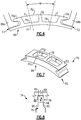
Figures 6 and 7 , in one embodiment, therib 76 is provided by theseal arc segment 66. In this embodiment, theslot 78 is provided by the carriage 68 (not shown).Therib 76 is circumferentially between thesupports 70a/70b and extends radially outward from a radiallyinner surface 79 of a pocket P formed at the radially outer side R2. In one example, therib 76 extends a radial distance such that the outer surface of therib 76 is flush with surrounding edges of the radially outer side R2 of thearc segment 66. - The
rib 76 extends axially, such that when it is received in anaxially extending slot 78 of thestatic carriage 68, the interlocking of therib 76 andslot 78 limits circumferential rotation of theseal arc segment 66. Therib 76 may extend axially from a first circumferentially and radially extending surface PS1 of the pocket P to a second opposite circumferentially and radially extending surface PS2. Therib 76 may extend axially across substantially the entireseal arc segment 66. -
Figure 8 illustrates the interface between therib 76 and theslot 78. Theslot 78 is provided by an axially and circumferentially extendingsurface 82, and two opposing radially and axially extendingsurfaces rib 76 is provided by a circumferentially and axially extendingsurface 84 and two opposing radially and axially extendingsurfaces rib 76 and theslot 78 are engaged to provide ananti-rotation interface 74, thesurface 82 of theslot 78 interfaces with thesurface 84 of therib 76. Thesurfaces slot 78 interface with thesurfaces rib 76. When therib 76 is received within theslot 78, the interfacing betweensurfaces surfaces - In one example, the
rib 76 is within the middle circumferential third M of the seal arc segment 66 (Figure 6 ), such that therib 76 is substantially central to thearc seal segment 66. A substantiallycentral rib 76 allows for the thermal growth of thearc seal segment 66 to be centered circumferentially. Additionally, controlling the circumferential position from a central location minimizes the differential radial motion of the seal arc segment on the rampedinterfaces 72a/72b, thus minimizing the radial clearance variation between theblade 64 tip and the seal arc segment surface R1. The circumferential distance from thefirst seal support 70a to therib 76 may be approximately equal to the circumferential distance from thesecond seal support 70b to therib 76. - As illustrated in
Figure 9 , the carriage may include acarriage body 97 and akey member 96, which provides theslot 78. Thekey member 96 may be a separate member attached to thecarriage body 97. In one example, thekey member 96 is placed onto theseal arc segment 66 such that therib 76 of theseal arc segment 66 is received in theslot 78 of thekey member 96. The joinedseal arc segment 66 andkey member 96 are then slid axially into thecarriage 68 at an axial end CA1 toward an axial end CA2, such that thekey member 96 is slid into an opening orlongitudinal slot 98 in thecarriage body 97. Theopening 98 is open in cross-section at an axial end CA1 and extends toward axial end CA2 to receive the axial sliding of thekey member 96 joined to theseal arc segment 66. Theopening 98 may extend radially outward from a radiallyinner surface 99 of thecarriage body 97. - As the
carriage 68 receives theseal arc segment 66, the first andsecond support members 68a/68b engage the first and second seal supports 70a/70b. Thesupport members 68a/68b provide radial support to prevent radially inward movement of theseal arc segment 66 that would be sufficient to disengage therib 76 from theslot 78. Theopening 98 may include abore 100 for receiving abolt 102 for fixing the key 96 to thecarriage body 97, for example. - The engagement of the
rib 76 and thekey member 96 is further illustrated inFigure 10 . Fixing thekey member 96 to thestatic carriage body 97 with therib 76 of theseal arc segment 66 received within theslot 78 of the key 96 limits circumferential rotation of theseal arc segment 66. - As illustrated in
Figures 11 and 12 , in another example, the key 196 provides therib 76 of theanti-rotation interface 74. The key 196 may be T-shaped in cross-section, and thecorresponding opening 198 and thecarriage 68 is also T-shaped in cross-section. Theseal arc segment 66 provides theslot 78, one example being shown inFigure 12 . Therib 76 of the key 196 is thus received in theslot 78 of theseal arc segment 66. Theslot 78 is circumferentially between the supports 70/7b and extends axially, as well as radially inward from the radially outer side R2 of theseal arc segment 66. As one alternative to the example shown inFigure 12 , the slot may extend farther radially inward to be even with thesurface 79 of the pocket P, such that two circumferentially spaced ribs may provide theslot 78. - When the
anti-rotation interface 74 is engaged, therib 76 of the key 196 is received in theslot 78 by extending radially inward of the radially outer side R2 of theseal arc segment 66 into theslot 78. Theslot 78 is within the middle circumferential third M of theseal arc segment 66, such that theslot 78 is substantially central to thearc seal segment 66. In another example, the circumferential distance from thefirst seal support 70a to theslot 78 may be approximately equal to the circumferential distance from thesecond seal support 70b to theslot 78. - After the
rib 76 of thekey member 196 is received theslot 78, theseal arc segment 66 may be slid axially into thecarriage 68, beginning at the axial end CA1 and toward axial end CA2, such that thekey member 196 slides into thecorresponding opening 198 of the carriage body. Theopening 198 is open at the axial end CA1 in cross section and extends axially toward the axial end CA2 to accommodate the axial sliding of the key 196 joined with theseal arc segment 66 through the axial end CA1 of thecarriage 68. Theopening 198 may extend radially outward from a radiallyinner surface 99 of thecarriage body 97. - As the
carriage 68 receives theseal arc segment 66, the first andsecond support members 68a/68b engage the first and second seal supports 70a/70b. Thesupport members 68a/68b provide radial support to prevent radially inward movement of theseal arc segment 66 that would be sufficient to disengage therib 76 from theslot 78. Fixing thekey member 196 to thestatic carriage body 97 with therib 76 engaged with theslot 78 of theseal arc segment 66 prevents circumferential rotation of theseal arc segment 66. - The
anti-rotation interface 74 can reduce tilting or rotation of thearc seal segment 66 relative to thecarriage 68, thereby reducing asymmetrical loading, asymmetrical thermal growth, and wear onsupports 70a/70b of theseal arc segment 66. By adding a centralanti rotation interface 74, theseal arc segment 66 can be positioned such that circumferential forces on theseal arc segment 66 are opposed by reaction forces of theanti-rotation interface 74, thus keeping the BOAS in the proper position during all operating conditions including blade rub. Theseal arc segment 66 can then grow thermally independently of the case and support structure, while limiting the variation inseal arc segment 66 to sealarc segment 66 end gap variation around the circumference of the engine. - When ceramic is utilized as the material for the
seal arc segment 66, the pocket P andrib 76 may be machined in the bisque state - the state before sintering to form the final densified ceramic, but after an intermediate heat treatment to the green state material. In the bisque state, the ceramic is relatively soft such that simple machining operations can be used to achieve desired shapes, unlike in the sintered state - where diamond tools are required for such machining operations. - The examples herein also illustrate a method for maintaining positioning in the
BOAS 60. For example, the method includes providing aseal arc segment 66 radially outward of arotor 62. Theseal arc segment 66 is supported on acarriage 68. The first andsecond support members 68a/68b of the carriage support theseal arc segment 66 at rampedinterfaces 72a/72b. Arib 76 is engaged with aslot 78 to restrict circumferential movement of theseal arc segment 66. - Although a combination of features is shown in the illustrated examples, not all of them need to be combined to realize the benefits of various embodiments of this disclosure. In other words, a system designed according to an embodiment of this disclosure will not necessarily include all of the features shown in any one of the Figures or all of the portions schematically shown in the Figures. Moreover, selected features of one example embodiment may be combined with selected features of other example embodiments.
- The preceding description is exemplary rather than limiting in nature. Variations and modifications to the disclosed examples may become apparent to those skilled in the art that do not necessarily depart from this disclosure. The scope of legal protection given to this disclosure can only be determined by studying the following claims.
Claims (15)
- A seal assembly, comprising:a seal arc segment (66) defining first and second seal supports (70a,70b);a carriage (68) defining first and second support members (68a,68b), the first support member (68a) supporting the seal arc segment (66) in a first ramped interface (72a) and the second support member (68b) supporting the seal arc segment (66) in a second ramped interface (72b) such that the seal arc segment (66) is circumferentially moveable with respect to the carriage (68); andan anti-rotation interface (74) in which the seal arc segment (66) and the carriage (68) are engaged, the anti-rotation interface (74) restricting circumferential movement of the seal arc segment (66).
- The seal assembly as recited in claim 1, wherein the anti-rotation interface (74) comprises a rib (76) and a slot (78);
wherein optionally the seal arc segment (66) defines the rib (76). - The seal assembly as recited in claim 2, wherein:the carriage (68) defines the slot (78); orthe slot (78) is defined by a key (96) received in a body of the carriage (68).
- The seal assembly as recited in any preceding claim, wherein the anti-rotation interface (74) is within the middle circumferential third of the seal arc segment (66).
- The seal assembly as recited in any preceding claim, wherein the carriage (68) is disposed substantially radially outward of the at least one seal segment (66); wherein optionally:the first carriage support is radially inward of the first seal support (70a), and the second carriage support is radially inward of the second seal support (70b).
- The seal assembly as recited in any preceding claim, wherein the seal arc segment (66) comprises ceramic.
- The seal assembly as recited in any preceding claim, wherein the first and second carriage supports define the ramped interfaces (72a,72b).
- The seal assembly as recited in any preceding claim, wherein the rib (76) extends axially, and the circumferential distance from the first seal support (70a) to the rib (76) is approximately equal to the circumferential distance from the second seal support (70b) to the rib (76).
- A method of sealing a rotor assembly, comprising:providing a seal arc segment (66) radially outward of a rotor (62), with respect to the axis of rotation of the rotor (62), the seal arc segment (66) defining first and second seal supports (70a,70b);supporting the seal arc segment (66) on a carriage (68) defining first and second support members (68a,68b), the first support member (68a) supporting the seal arc segment (66) in a first ramped interface (72) and the second support member (68b) supporting the seal arc segment (66) in a second ramped interface (72b) such that the seal arc segment (66) is circumferentially moveable with respect to the carriage (68); andengaging a rib (76) with a slot (78) to restrict circumferential movement of the seal arc segment (66).
- The method as recited in claim 9, wherein the seal arc segment (66) defines the rib (76).
- The method as recited in claim 9 or 10, wherein:the carriage (68) defines the slot (78); orwherein the slot (78) is defined by a key (96) received in a body of the carriage (68).
- A blade outer air seal, comprising:a seal body defining:a first support at a first circumferential end,a second support at a second circumferential end, anda mating feature circumferentially spaced from the first circumferential end and second circumferential end, wherein the mating feature is configured to prevent circumferential rotation of the seal body.
- The blade outer air seal as recited in claim 12, wherein the seal arc segment comprises ceramic.
- The blade outer air seal as recited in claim 12 or 13, wherein the mating feature is an axially elongated rib;
wherein optionally the rib is disposed in a pocket at a radially outer portion of the seal body. - The blade outer air seal as recited in claim 12, 13 or 14, wherein the seal body is monolithic.
Applications Claiming Priority (1)
| Application Number | Priority Date | Filing Date | Title |
|---|---|---|---|
| US15/071,352 US10138749B2 (en) | 2016-03-16 | 2016-03-16 | Seal anti-rotation feature |
Publications (2)
| Publication Number | Publication Date |
|---|---|
| EP3219923A1 true EP3219923A1 (en) | 2017-09-20 |
| EP3219923B1 EP3219923B1 (en) | 2018-12-12 |
Family
ID=58265874
Family Applications (1)
| Application Number | Title | Priority Date | Filing Date |
|---|---|---|---|
| EP17160060.4A Active EP3219923B1 (en) | 2016-03-16 | 2017-03-09 | Seal anti-rotation feature |
Country Status (2)
| Country | Link |
|---|---|
| US (2) | US10138749B2 (en) |
| EP (1) | EP3219923B1 (en) |
Families Citing this family (11)
| Publication number | Priority date | Publication date | Assignee | Title |
|---|---|---|---|---|
| US9759079B2 (en) | 2015-05-28 | 2017-09-12 | Rolls-Royce Corporation | Split line flow path seals |
| US10900371B2 (en) | 2017-07-27 | 2021-01-26 | Rolls-Royce North American Technologies, Inc. | Abradable coatings for high-performance systems |
| US10858950B2 (en) | 2017-07-27 | 2020-12-08 | Rolls-Royce North America Technologies, Inc. | Multilayer abradable coatings for high-performance systems |
| US10718226B2 (en) | 2017-11-21 | 2020-07-21 | Rolls-Royce Corporation | Ceramic matrix composite component assembly and seal |
| US10808565B2 (en) * | 2018-05-22 | 2020-10-20 | Rolls-Royce Plc | Tapered abradable coatings |
| US11248482B2 (en) * | 2019-07-19 | 2022-02-15 | Raytheon Technologies Corporation | CMC BOAS arrangement |
| US11073038B2 (en) | 2019-07-19 | 2021-07-27 | Raytheon Technologies Corporation | CMC BOAS arrangement |
| US11073037B2 (en) * | 2019-07-19 | 2021-07-27 | Raytheon Technologies Corporation | CMC BOAS arrangement |
| US11105214B2 (en) | 2019-07-19 | 2021-08-31 | Raytheon Technologies Corporation | CMC BOAS arrangement |
| US11125099B2 (en) | 2019-11-06 | 2021-09-21 | Raytheon Technologies Corporation | Boas arrangement with double dovetail attachments |
| US12492640B2 (en) * | 2024-05-30 | 2025-12-09 | General Electric Company | Turbine engine including a vane support and a vane |
Citations (3)
| Publication number | Priority date | Publication date | Assignee | Title |
|---|---|---|---|---|
| EP1076161A2 (en) * | 1999-08-12 | 2001-02-14 | ABB (Schweiz) AG | Tip clearance control between rotor and stator of a turbomachine |
| WO2015038341A1 (en) * | 2013-09-11 | 2015-03-19 | United Technologies Corporation | Blade outer air seal having angled retention hook |
| WO2015109292A1 (en) * | 2014-01-20 | 2015-07-23 | United Technologies Corporation | Retention clip for a blade outer air seal |
Family Cites Families (72)
| Publication number | Priority date | Publication date | Assignee | Title |
|---|---|---|---|---|
| US3892497A (en) * | 1974-05-14 | 1975-07-01 | Westinghouse Electric Corp | Axial flow turbine stationary blade and blade ring locking arrangement |
| US4087199A (en) * | 1976-11-22 | 1978-05-02 | General Electric Company | Ceramic turbine shroud assembly |
| US4394022A (en) * | 1981-09-29 | 1983-07-19 | Gilmore Richard F | Mechanically expandable annular seal |
| US4522559A (en) * | 1982-02-19 | 1985-06-11 | General Electric Company | Compressor casing |
| US4436311A (en) * | 1982-04-20 | 1984-03-13 | Brandon Ronald E | Segmented labyrinth-type shaft sealing system for fluid turbines |
| FR2540560B1 (en) | 1983-02-03 | 1987-06-12 | Snecma | DEVICE FOR SEALING MOBILE BLADES OF A TURBOMACHINE |
| US4728257A (en) * | 1986-06-18 | 1988-03-01 | The United States Of America As Represented By The Administrator Of The National Aeronautics And Space Administration | Thermal stress minimized, two component, turbine shroud seal |
| US5374068A (en) * | 1991-05-07 | 1994-12-20 | General Electric Co. | Method for providing uniform radial clearance of labyrinth seals between rotating and stationary components |
| US5165848A (en) * | 1991-07-09 | 1992-11-24 | General Electric Company | Vane liner with axially positioned heat shields |
| US5195868A (en) * | 1991-07-09 | 1993-03-23 | General Electric Company | Heat shield for a compressor/stator structure |
| US5618161A (en) * | 1995-10-17 | 1997-04-08 | Westinghouse Electric Corporation | Apparatus for restraining motion of a turbo-machine stationary vane |
| US5639210A (en) | 1995-10-23 | 1997-06-17 | United Technologies Corporation | Rotor blade outer tip seal apparatus |
| US5609469A (en) | 1995-11-22 | 1997-03-11 | United Technologies Corporation | Rotor assembly shroud |
| US5709388A (en) * | 1996-09-27 | 1998-01-20 | General Electric Co. | Variable clearance packing ring with guide for preventing circumferential displacement |
| US6142731A (en) * | 1997-07-21 | 2000-11-07 | Caterpillar Inc. | Low thermal expansion seal ring support |
| US6431825B1 (en) | 2000-07-28 | 2002-08-13 | Alstom (Switzerland) Ltd | Seal between static turbine parts |
| US6695316B2 (en) * | 2001-09-21 | 2004-02-24 | General Electric Company | Apparatus and methods for supporting a retractable packing ring |
| GB2385643B (en) | 2002-02-20 | 2005-05-18 | Cross Mfg Company | Improvements relating to a fluid seal |
| US6733235B2 (en) | 2002-03-28 | 2004-05-11 | General Electric Company | Shroud segment and assembly for a turbine engine |
| US6726448B2 (en) | 2002-05-15 | 2004-04-27 | General Electric Company | Ceramic turbine shroud |
| US7032904B2 (en) * | 2003-08-13 | 2006-04-25 | United Technologies Corporation | Inner air seal anti-rotation device |
| US7435049B2 (en) | 2004-03-30 | 2008-10-14 | General Electric Company | Sealing device and method for turbomachinery |
| US7052235B2 (en) | 2004-06-08 | 2006-05-30 | General Electric Company | Turbine engine shroud segment, hanger and assembly |
| GB2417528B (en) | 2004-08-23 | 2008-08-06 | Alstom Technology Ltd | Improved rope seal for gas turbine engines |
| US7527472B2 (en) | 2006-08-24 | 2009-05-05 | Siemens Energy, Inc. | Thermally sprayed conformal seal |
| US7650926B2 (en) | 2006-09-28 | 2010-01-26 | United Technologies Corporation | Blade outer air seals, cores, and manufacture methods |
| US9039358B2 (en) | 2007-01-03 | 2015-05-26 | United Technologies Corporation | Replaceable blade outer air seal design |
| US20090096174A1 (en) | 2007-02-28 | 2009-04-16 | United Technologies Corporation | Blade outer air seal for a gas turbine engine |
| US8123466B2 (en) | 2007-03-01 | 2012-02-28 | United Technologies Corporation | Blade outer air seal |
| US8303247B2 (en) | 2007-09-06 | 2012-11-06 | United Technologies Corporation | Blade outer air seal |
| US8128343B2 (en) * | 2007-09-21 | 2012-03-06 | Siemens Energy, Inc. | Ring segment coolant seal configuration |
| US8568091B2 (en) | 2008-02-18 | 2013-10-29 | United Technologies Corporation | Gas turbine engine systems and methods involving blade outer air seals |
| US8282136B2 (en) * | 2008-06-30 | 2012-10-09 | Mueller International, Llc | Slip on groove coupling with multiple sealing gasket |
| US8127204B2 (en) | 2008-08-15 | 2012-02-28 | Micron Technology, Inc. | Memory system and method using a memory device die stacked with a logic die using data encoding, and system using the memory system |
| US8534995B2 (en) | 2009-03-05 | 2013-09-17 | United Technologies Corporation | Turbine engine sealing arrangement |
| US8740551B2 (en) | 2009-08-18 | 2014-06-03 | Pratt & Whitney Canada Corp. | Blade outer air seal cooling |
| US8439636B1 (en) | 2009-10-20 | 2013-05-14 | Florida Turbine Technologies, Inc. | Turbine blade outer air seal |
| US8794911B2 (en) * | 2010-03-30 | 2014-08-05 | United Technologies Corporation | Anti-rotation slot for turbine vane |
| US8933263B2 (en) | 2010-12-29 | 2015-01-13 | Ecolab Usa Inc. | Water temperature as a means of controlling kinetics of onsite generated peracids |
| US8876458B2 (en) | 2011-01-25 | 2014-11-04 | United Technologies Corporation | Blade outer air seal assembly and support |
| US8827642B2 (en) | 2011-01-31 | 2014-09-09 | General Electric Company | Flexible seal for turbine engine |
| US8790067B2 (en) | 2011-04-27 | 2014-07-29 | United Technologies Corporation | Blade clearance control using high-CTE and low-CTE ring members |
| US8596963B1 (en) | 2011-07-07 | 2013-12-03 | Florida Turbine Technologies, Inc. | BOAS for a turbine |
| US8944756B2 (en) | 2011-07-15 | 2015-02-03 | United Technologies Corporation | Blade outer air seal assembly |
| US8920127B2 (en) | 2011-07-18 | 2014-12-30 | United Technologies Corporation | Turbine rotor non-metallic blade attachment |
| US8834113B2 (en) * | 2011-07-19 | 2014-09-16 | General Electric Company | Alignment member for steam turbine nozzle assembly |
| US20130113168A1 (en) | 2011-11-04 | 2013-05-09 | Paul M. Lutjen | Metal gasket for a gas turbine engine |
| US9175579B2 (en) * | 2011-12-15 | 2015-11-03 | General Electric Company | Low-ductility turbine shroud |
| US9169739B2 (en) * | 2012-01-04 | 2015-10-27 | United Technologies Corporation | Hybrid blade outer air seal for gas turbine engine |
| US9228447B2 (en) * | 2012-02-14 | 2016-01-05 | United Technologies Corporation | Adjustable blade outer air seal apparatus |
| US9347327B2 (en) * | 2012-06-14 | 2016-05-24 | Dresser-Rand Company | F-class gas turbine compressor exit guide vane repair |
| US8897424B2 (en) | 2012-07-11 | 2014-11-25 | Oracle International Corporation | Automatic clustering and visualization of data trends |
| US9574455B2 (en) | 2012-07-16 | 2017-02-21 | United Technologies Corporation | Blade outer air seal with cooling features |
| US9200530B2 (en) | 2012-07-20 | 2015-12-01 | United Technologies Corporation | Radial position control of case supported structure |
| US8640077B1 (en) | 2012-07-30 | 2014-01-28 | International Business Machines Corporation | Capturing mutual coupling effects between an integrated circuit chip and chip package |
| US9115596B2 (en) | 2012-08-07 | 2015-08-25 | United Technologies Corporation | Blade outer air seal having anti-rotation feature |
| US20140127006A1 (en) | 2012-11-05 | 2014-05-08 | United Technologies Corporation | Blade outer air seal |
| US9587504B2 (en) | 2012-11-13 | 2017-03-07 | United Technologies Corporation | Carrier interlock |
| US9447696B2 (en) | 2012-12-27 | 2016-09-20 | United Technologies Corporation | Blade outer air seal system for controlled tip clearance |
| WO2015002673A2 (en) | 2013-02-20 | 2015-01-08 | United Technologies Corporation | Gas turbine engine seal assembly |
| US9957830B2 (en) | 2013-03-07 | 2018-05-01 | United Technologies Corporation | Hybrid passive and active tip clearance system |
| US9835174B2 (en) * | 2013-03-15 | 2017-12-05 | Ansaldo Energia Ip Uk Limited | Anti-rotation lug and splitline jumper |
| EP3025042A4 (en) | 2013-07-23 | 2016-08-17 | United Technologies Corp | RADIALLY POSITION CONTROL OF CANNEL CONNECTED CARTER SUPPORT STRUCTURE |
| EP3044427B8 (en) | 2013-09-12 | 2021-04-07 | Raytheon Technologies Corporation | Gas turbine engine and corresponding method for regulating blade tip clearance |
| WO2015061108A1 (en) | 2013-10-24 | 2015-04-30 | United Technologies Corporation | Annular cartridge seal |
| US10550706B2 (en) | 2013-12-12 | 2020-02-04 | United Technolgies Corporation | Wrapped dog bone seal |
| WO2015112354A1 (en) | 2014-01-27 | 2015-07-30 | United Technologies Corporation | Blade outer air seal mount |
| US10145308B2 (en) | 2014-02-10 | 2018-12-04 | United Technologies Corporation | Gas turbine engine ring seal |
| US10309243B2 (en) | 2014-05-23 | 2019-06-04 | United Technologies Corporation | Grooved blade outer air seals |
| US20160003078A1 (en) | 2014-07-02 | 2016-01-07 | United Technologies Corporation | Gasket with thermal and wear protective fabric |
| US10370991B2 (en) * | 2014-11-07 | 2019-08-06 | United Technologies Corporation | Gas turbine engine and seal assembly therefore |
| US10378371B2 (en) * | 2014-12-18 | 2019-08-13 | United Technologies Corporation | Anti-rotation vane |
-
2016
- 2016-03-16 US US15/071,352 patent/US10138749B2/en active Active
-
2017
- 2017-03-09 EP EP17160060.4A patent/EP3219923B1/en active Active
-
2018
- 2018-09-27 US US16/143,589 patent/US10436053B2/en active Active
Patent Citations (3)
| Publication number | Priority date | Publication date | Assignee | Title |
|---|---|---|---|---|
| EP1076161A2 (en) * | 1999-08-12 | 2001-02-14 | ABB (Schweiz) AG | Tip clearance control between rotor and stator of a turbomachine |
| WO2015038341A1 (en) * | 2013-09-11 | 2015-03-19 | United Technologies Corporation | Blade outer air seal having angled retention hook |
| WO2015109292A1 (en) * | 2014-01-20 | 2015-07-23 | United Technologies Corporation | Retention clip for a blade outer air seal |
Also Published As
| Publication number | Publication date |
|---|---|
| US10436053B2 (en) | 2019-10-08 |
| EP3219923B1 (en) | 2018-12-12 |
| US20170268367A1 (en) | 2017-09-21 |
| US20190024526A1 (en) | 2019-01-24 |
| US10138749B2 (en) | 2018-11-27 |
Similar Documents
| Publication | Publication Date | Title |
|---|---|---|
| US10436053B2 (en) | Seal anti-rotation feature | |
| EP3219933B1 (en) | Seal assembly, gas turbine having the same, and method of assembling a seal assembly | |
| EP3219935B1 (en) | Turbine engine blade outer air seal with load-transmitting carriage | |
| EP2875224B1 (en) | Radial position control of case supported structure | |
| EP3219938A1 (en) | Blade outer air seal support, method for protecting blade outer air seal, and blade outer air seal assembly | |
| EP3219924B1 (en) | Turbine engine blade outer air seal with load transmitting cover plate | |
| EP3219930B1 (en) | Blade outer air seal with a heat shield | |
| EP3219934B1 (en) | Seal assembly for gas turbine engine | |
| EP3219928B1 (en) | Blade outer air seal with spring centering | |
| EP3219932B1 (en) | Blade outer air seal with flow guide manifold | |
| US20200080439A1 (en) | Boas enhanced heat transfer surface | |
| EP3219927B1 (en) | Blade outer air seal with a heat shield | |
| EP3228830B1 (en) | Blade outer air seal with centrally mounted seal arc segments |
Legal Events
| Date | Code | Title | Description |
|---|---|---|---|
| PUAI | Public reference made under article 153(3) epc to a published international application that has entered the european phase |
Free format text: ORIGINAL CODE: 0009012 |
|
| STAA | Information on the status of an ep patent application or granted ep patent |
Free format text: STATUS: THE APPLICATION HAS BEEN PUBLISHED |
|
| AK | Designated contracting states |
Kind code of ref document: A1 Designated state(s): AL AT BE BG CH CY CZ DE DK EE ES FI FR GB GR HR HU IE IS IT LI LT LU LV MC MK MT NL NO PL PT RO RS SE SI SK SM TR |
|
| AX | Request for extension of the european patent |
Extension state: BA ME |
|
| STAA | Information on the status of an ep patent application or granted ep patent |
Free format text: STATUS: REQUEST FOR EXAMINATION WAS MADE |
|
| 17P | Request for examination filed |
Effective date: 20180319 |
|
| RBV | Designated contracting states (corrected) |
Designated state(s): AL AT BE BG CH CY CZ DE DK EE ES FI FR GB GR HR HU IE IS IT LI LT LU LV MC MK MT NL NO PL PT RO RS SE SI SK SM TR |
|
| RIC1 | Information provided on ipc code assigned before grant |
Ipc: F01D 5/28 20060101AFI20180425BHEP Ipc: F01D 11/12 20060101ALI20180425BHEP Ipc: F16J 15/34 20060101ALI20180425BHEP Ipc: F01D 25/24 20060101ALI20180425BHEP Ipc: F01D 11/08 20060101ALI20180425BHEP Ipc: F01D 9/04 20060101ALI20180425BHEP |
|
| GRAP | Despatch of communication of intention to grant a patent |
Free format text: ORIGINAL CODE: EPIDOSNIGR1 |
|
| STAA | Information on the status of an ep patent application or granted ep patent |
Free format text: STATUS: GRANT OF PATENT IS INTENDED |
|
| INTG | Intention to grant announced |
Effective date: 20180614 |
|
| GRAS | Grant fee paid |
Free format text: ORIGINAL CODE: EPIDOSNIGR3 |
|
| GRAA | (expected) grant |
Free format text: ORIGINAL CODE: 0009210 |
|
| STAA | Information on the status of an ep patent application or granted ep patent |
Free format text: STATUS: THE PATENT HAS BEEN GRANTED |
|
| AK | Designated contracting states |
Kind code of ref document: B1 Designated state(s): AL AT BE BG CH CY CZ DE DK EE ES FI FR GB GR HR HU IE IS IT LI LT LU LV MC MK MT NL NO PL PT RO RS SE SI SK SM TR |
|
| REG | Reference to a national code |
Ref country code: GB Ref legal event code: FG4D |
|
| REG | Reference to a national code |
Ref country code: CH Ref legal event code: EP |
|
| REG | Reference to a national code |
Ref country code: AT Ref legal event code: REF Ref document number: 1076250 Country of ref document: AT Kind code of ref document: T Effective date: 20181215 |
|
| REG | Reference to a national code |
Ref country code: DE Ref legal event code: R096 Ref document number: 602017001261 Country of ref document: DE |
|
| REG | Reference to a national code |
Ref country code: IE Ref legal event code: FG4D |
|
| REG | Reference to a national code |
Ref country code: NL Ref legal event code: MP Effective date: 20181212 |
|
| REG | Reference to a national code |
Ref country code: LT Ref legal event code: MG4D |
|
| PG25 | Lapsed in a contracting state [announced via postgrant information from national office to epo] |
Ref country code: HR Free format text: LAPSE BECAUSE OF FAILURE TO SUBMIT A TRANSLATION OF THE DESCRIPTION OR TO PAY THE FEE WITHIN THE PRESCRIBED TIME-LIMIT Effective date: 20181212 Ref country code: NO Free format text: LAPSE BECAUSE OF FAILURE TO SUBMIT A TRANSLATION OF THE DESCRIPTION OR TO PAY THE FEE WITHIN THE PRESCRIBED TIME-LIMIT Effective date: 20190312 Ref country code: LV Free format text: LAPSE BECAUSE OF FAILURE TO SUBMIT A TRANSLATION OF THE DESCRIPTION OR TO PAY THE FEE WITHIN THE PRESCRIBED TIME-LIMIT Effective date: 20181212 Ref country code: FI Free format text: LAPSE BECAUSE OF FAILURE TO SUBMIT A TRANSLATION OF THE DESCRIPTION OR TO PAY THE FEE WITHIN THE PRESCRIBED TIME-LIMIT Effective date: 20181212 Ref country code: BG Free format text: LAPSE BECAUSE OF FAILURE TO SUBMIT A TRANSLATION OF THE DESCRIPTION OR TO PAY THE FEE WITHIN THE PRESCRIBED TIME-LIMIT Effective date: 20190312 Ref country code: LT Free format text: LAPSE BECAUSE OF FAILURE TO SUBMIT A TRANSLATION OF THE DESCRIPTION OR TO PAY THE FEE WITHIN THE PRESCRIBED TIME-LIMIT Effective date: 20181212 Ref country code: ES Free format text: LAPSE BECAUSE OF FAILURE TO SUBMIT A TRANSLATION OF THE DESCRIPTION OR TO PAY THE FEE WITHIN THE PRESCRIBED TIME-LIMIT Effective date: 20181212 |
|
| REG | Reference to a national code |
Ref country code: AT Ref legal event code: MK05 Ref document number: 1076250 Country of ref document: AT Kind code of ref document: T Effective date: 20181212 |
|
| PG25 | Lapsed in a contracting state [announced via postgrant information from national office to epo] |
Ref country code: GR Free format text: LAPSE BECAUSE OF FAILURE TO SUBMIT A TRANSLATION OF THE DESCRIPTION OR TO PAY THE FEE WITHIN THE PRESCRIBED TIME-LIMIT Effective date: 20190313 Ref country code: AL Free format text: LAPSE BECAUSE OF FAILURE TO SUBMIT A TRANSLATION OF THE DESCRIPTION OR TO PAY THE FEE WITHIN THE PRESCRIBED TIME-LIMIT Effective date: 20181212 Ref country code: SE Free format text: LAPSE BECAUSE OF FAILURE TO SUBMIT A TRANSLATION OF THE DESCRIPTION OR TO PAY THE FEE WITHIN THE PRESCRIBED TIME-LIMIT Effective date: 20181212 Ref country code: RS Free format text: LAPSE BECAUSE OF FAILURE TO SUBMIT A TRANSLATION OF THE DESCRIPTION OR TO PAY THE FEE WITHIN THE PRESCRIBED TIME-LIMIT Effective date: 20181212 |
|
| PG25 | Lapsed in a contracting state [announced via postgrant information from national office to epo] |
Ref country code: NL Free format text: LAPSE BECAUSE OF FAILURE TO SUBMIT A TRANSLATION OF THE DESCRIPTION OR TO PAY THE FEE WITHIN THE PRESCRIBED TIME-LIMIT Effective date: 20181212 |
|
| PG25 | Lapsed in a contracting state [announced via postgrant information from national office to epo] |
Ref country code: PL Free format text: LAPSE BECAUSE OF FAILURE TO SUBMIT A TRANSLATION OF THE DESCRIPTION OR TO PAY THE FEE WITHIN THE PRESCRIBED TIME-LIMIT Effective date: 20181212 Ref country code: CZ Free format text: LAPSE BECAUSE OF FAILURE TO SUBMIT A TRANSLATION OF THE DESCRIPTION OR TO PAY THE FEE WITHIN THE PRESCRIBED TIME-LIMIT Effective date: 20181212 Ref country code: IT Free format text: LAPSE BECAUSE OF FAILURE TO SUBMIT A TRANSLATION OF THE DESCRIPTION OR TO PAY THE FEE WITHIN THE PRESCRIBED TIME-LIMIT Effective date: 20181212 Ref country code: PT Free format text: LAPSE BECAUSE OF FAILURE TO SUBMIT A TRANSLATION OF THE DESCRIPTION OR TO PAY THE FEE WITHIN THE PRESCRIBED TIME-LIMIT Effective date: 20190412 |
|
| PG25 | Lapsed in a contracting state [announced via postgrant information from national office to epo] |
Ref country code: RO Free format text: LAPSE BECAUSE OF FAILURE TO SUBMIT A TRANSLATION OF THE DESCRIPTION OR TO PAY THE FEE WITHIN THE PRESCRIBED TIME-LIMIT Effective date: 20181212 Ref country code: SK Free format text: LAPSE BECAUSE OF FAILURE TO SUBMIT A TRANSLATION OF THE DESCRIPTION OR TO PAY THE FEE WITHIN THE PRESCRIBED TIME-LIMIT Effective date: 20181212 Ref country code: SM Free format text: LAPSE BECAUSE OF FAILURE TO SUBMIT A TRANSLATION OF THE DESCRIPTION OR TO PAY THE FEE WITHIN THE PRESCRIBED TIME-LIMIT Effective date: 20181212 Ref country code: EE Free format text: LAPSE BECAUSE OF FAILURE TO SUBMIT A TRANSLATION OF THE DESCRIPTION OR TO PAY THE FEE WITHIN THE PRESCRIBED TIME-LIMIT Effective date: 20181212 Ref country code: IS Free format text: LAPSE BECAUSE OF FAILURE TO SUBMIT A TRANSLATION OF THE DESCRIPTION OR TO PAY THE FEE WITHIN THE PRESCRIBED TIME-LIMIT Effective date: 20190412 |
|
| REG | Reference to a national code |
Ref country code: DE Ref legal event code: R097 Ref document number: 602017001261 Country of ref document: DE |
|
| PLBE | No opposition filed within time limit |
Free format text: ORIGINAL CODE: 0009261 |
|
| STAA | Information on the status of an ep patent application or granted ep patent |
Free format text: STATUS: NO OPPOSITION FILED WITHIN TIME LIMIT |
|
| PG25 | Lapsed in a contracting state [announced via postgrant information from national office to epo] |
Ref country code: SI Free format text: LAPSE BECAUSE OF FAILURE TO SUBMIT A TRANSLATION OF THE DESCRIPTION OR TO PAY THE FEE WITHIN THE PRESCRIBED TIME-LIMIT Effective date: 20181212 Ref country code: MC Free format text: LAPSE BECAUSE OF FAILURE TO SUBMIT A TRANSLATION OF THE DESCRIPTION OR TO PAY THE FEE WITHIN THE PRESCRIBED TIME-LIMIT Effective date: 20181212 Ref country code: DK Free format text: LAPSE BECAUSE OF FAILURE TO SUBMIT A TRANSLATION OF THE DESCRIPTION OR TO PAY THE FEE WITHIN THE PRESCRIBED TIME-LIMIT Effective date: 20181212 Ref country code: AT Free format text: LAPSE BECAUSE OF FAILURE TO SUBMIT A TRANSLATION OF THE DESCRIPTION OR TO PAY THE FEE WITHIN THE PRESCRIBED TIME-LIMIT Effective date: 20181212 |
|
| 26N | No opposition filed |
Effective date: 20190913 |
|
| PG25 | Lapsed in a contracting state [announced via postgrant information from national office to epo] |
Ref country code: LU Free format text: LAPSE BECAUSE OF NON-PAYMENT OF DUE FEES Effective date: 20190309 |
|
| REG | Reference to a national code |
Ref country code: BE Ref legal event code: MM Effective date: 20190331 |
|
| PG25 | Lapsed in a contracting state [announced via postgrant information from national office to epo] |
Ref country code: IE Free format text: LAPSE BECAUSE OF NON-PAYMENT OF DUE FEES Effective date: 20190309 |
|
| PG25 | Lapsed in a contracting state [announced via postgrant information from national office to epo] |
Ref country code: BE Free format text: LAPSE BECAUSE OF NON-PAYMENT OF DUE FEES Effective date: 20190331 |
|
| PG25 | Lapsed in a contracting state [announced via postgrant information from national office to epo] |
Ref country code: TR Free format text: LAPSE BECAUSE OF FAILURE TO SUBMIT A TRANSLATION OF THE DESCRIPTION OR TO PAY THE FEE WITHIN THE PRESCRIBED TIME-LIMIT Effective date: 20181212 |
|
| PG25 | Lapsed in a contracting state [announced via postgrant information from national office to epo] |
Ref country code: MT Free format text: LAPSE BECAUSE OF NON-PAYMENT OF DUE FEES Effective date: 20190309 |
|
| REG | Reference to a national code |
Ref country code: CH Ref legal event code: PL |
|
| PG25 | Lapsed in a contracting state [announced via postgrant information from national office to epo] |
Ref country code: CH Free format text: LAPSE BECAUSE OF NON-PAYMENT OF DUE FEES Effective date: 20200331 Ref country code: LI Free format text: LAPSE BECAUSE OF NON-PAYMENT OF DUE FEES Effective date: 20200331 |
|
| PG25 | Lapsed in a contracting state [announced via postgrant information from national office to epo] |
Ref country code: CY Free format text: LAPSE BECAUSE OF FAILURE TO SUBMIT A TRANSLATION OF THE DESCRIPTION OR TO PAY THE FEE WITHIN THE PRESCRIBED TIME-LIMIT Effective date: 20181212 |
|
| PG25 | Lapsed in a contracting state [announced via postgrant information from national office to epo] |
Ref country code: HU Free format text: LAPSE BECAUSE OF FAILURE TO SUBMIT A TRANSLATION OF THE DESCRIPTION OR TO PAY THE FEE WITHIN THE PRESCRIBED TIME-LIMIT; INVALID AB INITIO Effective date: 20170309 |
|
| PG25 | Lapsed in a contracting state [announced via postgrant information from national office to epo] |
Ref country code: MK Free format text: LAPSE BECAUSE OF FAILURE TO SUBMIT A TRANSLATION OF THE DESCRIPTION OR TO PAY THE FEE WITHIN THE PRESCRIBED TIME-LIMIT Effective date: 20181212 |
|
| REG | Reference to a national code |
Ref country code: DE Ref legal event code: R081 Ref document number: 602017001261 Country of ref document: DE Owner name: RAYTHEON TECHNOLOGIES CORPORATION (N.D.GES.D.S, US Free format text: FORMER OWNER: UNITED TECHNOLOGIES CORPORATION, FARMINGTON, CONN., US Ref country code: DE Ref legal event code: R081 Ref document number: 602017001261 Country of ref document: DE Owner name: RTX CORPORATION (N.D.GES.D. STAATES DELAWARE),, US Free format text: FORMER OWNER: UNITED TECHNOLOGIES CORPORATION, FARMINGTON, CONN., US |
|
| P01 | Opt-out of the competence of the unified patent court (upc) registered |
Effective date: 20230520 |
|
| REG | Reference to a national code |
Ref country code: DE Ref legal event code: R081 Ref document number: 602017001261 Country of ref document: DE Owner name: RTX CORPORATION (N.D.GES.D. STAATES DELAWARE),, US Free format text: FORMER OWNER: RAYTHEON TECHNOLOGIES CORPORATION (N.D.GES.D.STAATES DELAWARE), ARLINGTON, VA, US |
|
| PGFP | Annual fee paid to national office [announced via postgrant information from national office to epo] |
Ref country code: GB Payment date: 20260219 Year of fee payment: 10 |
|
| PGFP | Annual fee paid to national office [announced via postgrant information from national office to epo] |
Ref country code: DE Payment date: 20260219 Year of fee payment: 10 |
|
| PGFP | Annual fee paid to national office [announced via postgrant information from national office to epo] |
Ref country code: FR Payment date: 20260219 Year of fee payment: 10 |