EP3219863A1 - A wc suite - Google Patents
A wc suite Download PDFInfo
- Publication number
- EP3219863A1 EP3219863A1 EP16160720.5A EP16160720A EP3219863A1 EP 3219863 A1 EP3219863 A1 EP 3219863A1 EP 16160720 A EP16160720 A EP 16160720A EP 3219863 A1 EP3219863 A1 EP 3219863A1
- Authority
- EP
- European Patent Office
- Prior art keywords
- water
- bowl
- flush box
- flush
- suite
- Prior art date
- Legal status (The legal status is an assumption and is not a legal conclusion. Google has not performed a legal analysis and makes no representation as to the accuracy of the status listed.)
- Granted
Links
Images


Classifications
-
- E—FIXED CONSTRUCTIONS
- E03—WATER SUPPLY; SEWERAGE
- E03D—WATER-CLOSETS OR URINALS WITH FLUSHING DEVICES; FLUSHING VALVES THEREFOR
- E03D11/00—Other component parts of water-closets, e.g. noise-reducing means in the flushing system, flushing pipes mounted in the bowl, seals for the bowl outlet, devices preventing overflow of the bowl contents; devices forming a water seal in the bowl after flushing, devices eliminating obstructions in the bowl outlet or preventing backflow of water and excrements from the waterpipe
- E03D11/13—Parts or details of bowls; Special adaptations of pipe joints or couplings for use with bowls, e.g. provisions in bowl construction preventing backflow of waste-water from the bowl in the flushing pipe or cistern, provisions for a secondary flushing, for noise-reducing
-
- E—FIXED CONSTRUCTIONS
- E03—WATER SUPPLY; SEWERAGE
- E03D—WATER-CLOSETS OR URINALS WITH FLUSHING DEVICES; FLUSHING VALVES THEREFOR
- E03D11/00—Other component parts of water-closets, e.g. noise-reducing means in the flushing system, flushing pipes mounted in the bowl, seals for the bowl outlet, devices preventing overflow of the bowl contents; devices forming a water seal in the bowl after flushing, devices eliminating obstructions in the bowl outlet or preventing backflow of water and excrements from the waterpipe
Definitions
- the present invention relates to a WC suite. More particularly, the present invention relates to an improved WC suite which reduces trickles after a flush.
- the flushing system of such WC suites may e.g. be designed to allow flushing water to enter the bowl by gravity by arranging a flushing cistern at a level vertically above a water outlet connected to the WC bowl.
- the flushing cistern contains a certain volume of flushing water, which is at least partially emptied when a user initiates a flush.
- the flushing water flows from the cistern out through an outlet valve, and into the WC bowl via a flow path inside the WC suite.
- the interior areas may be constructed in very specific manner due to the complex manufacturing techniques used.
- the flow path extending from the outlet valve of the water cistern to the inlet of the WC bowl is tilted downwards.
- a rim or other flow distributor provided for forcing the flushing water to flow along the entire inner surface of the WC bowl.
- a small amount of water will however hit the rim (or other flow distributor device), and bounce backwards. The backflow of water will consequently follow the flow path between the inlet of the WC bowl and the outlet of the cistern.
- the backflow of water will not flow all the way back to the cistern, but it will instead accumulate in a small compartment arranged inside the WC suite behind the cistern outlet, being in fluid communication only with the flow path extending from the cistern outlet and the inlet of the WC bowl.
- This small compartment is commonly denoted as the flush box.
- the problem of dripping water may be at least partly reduced in prior art system by using a water distributor arranged under the rim of the WC suit.
- a water distributor arranged under the rim of the WC suit.
- such water distributors are not desirable due to for example the design of the toilet or due to cleaning and hygiene aspects.
- the present invention preferably seeks to mitigate or eliminate one or more of the above-identified deficiencies in the art singly or in any combination and solves at least the above mentioned problems by providing an improved WC suite.
- a WC suit comprises a water cistern, a WC bowl, and a flow path extending between an outlet of the water cistern and an inlet of the WC bowl for guiding flushing water during a flush, said WC suite further comprising a flush box arranged in fluid communication with said flow path such that flushing water bouncing at the inlet of the WC bowl will accumulate therein.
- the WC suite is characterized in that the flush box is in fluid communication with a sewer pipe connected to an outlet of the WC bowl, wherein said flush box is provided with a water trap.
- the flush box may be aligned with the sewer pipe along a vertical line.
- the flush box may be in fluid communication with the sewer pipe by means of an orifice provided in a wall of said flush box. This allows the bouncing water to travel directly down the sewer pipe instead of dripping back into the WC bowl where it creates stains.
- the flush box may comprise a dividing wall extending downwards into said flush box, said dividing wall forming part of said water trap.
- the water trap eliminates or at least reduces odour gases to escape from the WC suit.
- the flow path may be extending between the flush box and the inlet of the WC bowl may be tilted upwards.
- the accumulated water in the flush box will thus be guided to flow towards the water trap instead of flowing back towards the WC bowl.
- a flushing system 10 for flushing water into a WC bowl 40 of a WC suit 100 is shown.
- the flushing system 10 is constructed to allow a user of an associated WC suit 100 to flush the toilet after use, and for this purpose the flushing system 10, and hence the WC suite 100, includes a water cistern 20 and a flushing mechanism 30.
- the water cistern 20 is in fluid communication with the WC bowl 40 by means of an outlet 12 being controlled to open by means of the flushing mechanism 30.
- the water cistern 20 is capable of storing water between flushes and is in fluid communication with the WC bowl 40 by means of the outlet 12 being controlled to open by means of the flushing mechanism 30.
- the flushing mechanism 30 is constructed to open and close the outlet 12 when the user operates a flush initiation means, such as a push button 32 arranged at the upper end of the water cistern 20.
- a flush initiation means such as a push button 32 arranged at the upper end of the water cistern 20.
- the outlet 12 When pressing the flush button 32, the outlet 12 will open, i.e. it will be in fluid communication with the water cistern 20, to allow the water enclosed within the water cistern 20 to drain out from the outlet 12 and into the WC bowl 40.
- the water After passing the outlet 12, the water will pass through a flow path 14 which guides the flushing water through an opening 42 leading into the WC bowl 40.
- the flow path 14 extends between the outlet 12 of the water cistern 20 and an inlet 48 of the WC bowl 40.
- the WC bowl 40 is constructed with a bend 44 creating an integrated water trap in order to eliminate or at least reduce odours gases that are allowed to flow from a sewer pipe 46, into the WC bowl 40 and further into the surrounding bathroom. After the flushing water has passed the bend 44, the water is led out from the WC bowl 40 into the sewer pipe 46.
- the flush box 50 is an enclosure, or compartment, where water will accumulate during flushes.
- the inventors of the present invention have realized, after inventive and insightful reasoning that by arranging a water trap 56 in the flush box 50 and arranging the flush box 50 to be in fluid communication with the sewer pipe 46 the above mentioned problems will be greatly reduced. Instead of having water trickling for several minutes, the water dropping has now been reduced to merely a few seconds. The reduction of the amount of water trickling thus greatly reduces the risks of stains in the toilet bowl 40.
- the flush box 50 comprises two opposite side walls 58, 59 and one bottom surface 57 forming an enclosure. It should be realized that additional side walls are also provided, however they are not shown.
- the flush box 50 further comprises a dividing wall 52 which extends downwards into the flush box 50, but not entirely to the bottom of the flush box 50.
- the dividing wall 52 forms part of the water trap 56.
- the water trap 56 may thus be in the form of a U-bend or N-shaped structure, formed by the side walls 58, 59, the bottom surface 57 as well as the dividing wall 52.
- the height of the water enclosed in the water trap 56 may be between 30 and 70 mm, and more preferably around 50 mm.
- the height of the enclosed water is determined by the height of the two side walls 58, 59 and should be chosen to cope with standardised regulations.
- an orifice 54 is arranged in order to connect the flush box 40 to the sewer pipe 46.
- the flush box 50 is thus in direct fluid communication with the sewer pipe 46 by means of the orifice 54.
- the flush box 50 is aligned with the sewer pipe 46 along a vertical line, so that when the flush box 50 fills up during a flush, the water will flow through the orifice 54 vertically down towards the sewer pipe 46.
- the flush box 50 and its water trap 56 are preferably constructed by ceramic or other durable materials. In one embodiment the flush box 50 and the WC bowl 40 are constructed by the same material. The flush box 50 and its water trap 56 may be an integrated structure with the rest of the WC bowl 40. The water trap 56 is thus formed simultaneously with the rest of the WC bowl 40 which greatly reduces manufacturing costs.
- Fig. 3a shows an exemplified situation where the water trap 56 of the flush box 50 starts to fill up with water just after a flush has occurred.
- the water which bounces at the inlet 48 of the WC bowl 40 will be lead into the flow path 14 leading to the flush box 50 and the water trap 56.
- the flow path 14 is tilted so as to guide the water towards the water trap 56. This restricts the direction of the water flow after a flush.
- the inlet 48 of the WC bowl 40 is arranged at a higher level compared to the flush box 50, which creates a tilted flow path 14.
- the flow path 14 is tilted so that the highest point is arranged near the inlet 48 of the WC bowl 40 and the lowest point is arranged near the water trap 56 of the flush box 50.
- the flow path 14 is thus tilted upwards. The flushing water will flow in a direction downwards, while bouncing back from the inlet 48 towards the flush box 50.
- Fig. 3b shows the situation where the flush box 50 is fully filed with water.
- the remaining water in the flush box 50 will flow out through the orifice 54 down towards the sewer pipe 46.
- the water will thus not be dripping on the toilet bowl, but will instead be lead through the water trap 56 into the sewer pipe 46.
- the WC suits 100 shown in Fig. 1-3 are of a rimless design i.e. the inlet 48 of the WC bowl 40 is not a rim.
- the inlet 48, or flow distributor device may be a single lip. The lip is arranged at the back of the upper part of the toilet bowl 40 and releases the flushing water from the cistern 20 into the WC bowl 40.
- a WC suite having a flow distributor device such as a rim.
- the WC suit 100 is of a rimless design. Having a rimless design eliminates the possibility to arrange a water distributor in the WC suite 100 (since it normally is arranged under the rim of the WC suit 100) in order to reduce the problems of water trickles. The present invention is thus particularly useful for toilets being of a rimless design.
Landscapes
- Health & Medical Sciences (AREA)
- Life Sciences & Earth Sciences (AREA)
- Engineering & Computer Science (AREA)
- Hydrology & Water Resources (AREA)
- Public Health (AREA)
- Water Supply & Treatment (AREA)
- Sanitary Device For Flush Toilet (AREA)
- Bathtubs, Showers, And Their Attachments (AREA)
Abstract
Description
- The present invention relates to a WC suite. More particularly, the present invention relates to an improved WC suite which reduces trickles after a flush.
- Many different types of WC suites are available on the market. The flushing system of such WC suites may e.g. be designed to allow flushing water to enter the bowl by gravity by arranging a flushing cistern at a level vertically above a water outlet connected to the WC bowl. In such a system, the flushing cistern contains a certain volume of flushing water, which is at least partially emptied when a user initiates a flush.
- The flushing water flows from the cistern out through an outlet valve, and into the WC bowl via a flow path inside the WC suite. Especially for ceramic WC suites the interior areas may be constructed in very specific manner due to the complex manufacturing techniques used. In particular, in today's WC suites the flow path extending from the outlet valve of the water cistern to the inlet of the WC bowl is tilted downwards. When water flows during a flush the majority of the water will enter the WC bowl via a rim or other flow distributor provided for forcing the flushing water to flow along the entire inner surface of the WC bowl. A small amount of water will however hit the rim (or other flow distributor device), and bounce backwards. The backflow of water will consequently follow the flow path between the inlet of the WC bowl and the outlet of the cistern.
- The backflow of water will not flow all the way back to the cistern, but it will instead accumulate in a small compartment arranged inside the WC suite behind the cistern outlet, being in fluid communication only with the flow path extending from the cistern outlet and the inlet of the WC bowl. This small compartment is commonly denoted as the flush box.
- As water accumulates in the flush box, it will eventually start to flow back into the WC bowl due to the tilted flow path from the flush box to the inlet of the WC bowl. This kind of return flow normally begins when the flush is completed, and the flow rate is usually very low. Hence, many WC suites will suffer from slow water trickles after a completed flush. This water dropping could last from several seconds up to several minutes. The water trickles are particular problematic in areas with calcareous water since the water drops of calcareous water create lime deposits in the back part of the toilet bowl, which are very difficult to remove.
- The problem of dripping water may be at least partly reduced in prior art system by using a water distributor arranged under the rim of the WC suit. However, in some situations such water distributors are not desirable due to for example the design of the toilet or due to cleaning and hygiene aspects.
- There is thus a need for a WC suite that eliminates the problems of water trickles after a flush in an improved manner.
- Accordingly, the present invention preferably seeks to mitigate or eliminate one or more of the above-identified deficiencies in the art singly or in any combination and solves at least the above mentioned problems by providing an improved WC suite.
- According to a first aspect, a WC suit is provided. The WC suit comprises a water cistern, a WC bowl, and a flow path extending between an outlet of the water cistern and an inlet of the WC bowl for guiding flushing water during a flush, said WC suite further comprising a flush box arranged in fluid communication with said flow path such that flushing water bouncing at the inlet of the WC bowl will accumulate therein. The WC suite is characterized in that the flush box is in fluid communication with a sewer pipe connected to an outlet of the WC bowl, wherein said flush box is provided with a water trap.
- The flush box may be aligned with the sewer pipe along a vertical line. The flush box may be in fluid communication with the sewer pipe by means of an orifice provided in a wall of said flush box. This allows the bouncing water to travel directly down the sewer pipe instead of dripping back into the WC bowl where it creates stains.
- The flush box may comprise a dividing wall extending downwards into said flush box, said dividing wall forming part of said water trap. The water trap eliminates or at least reduces odour gases to escape from the WC suit.
- The flow path may be extending between the flush box and the inlet of the WC bowl may be tilted upwards. The accumulated water in the flush box will thus be guided to flow towards the water trap instead of flowing back towards the WC bowl.
- Further objects, features and advantages will appear from the following detailed description, with reference being made to the accompanying drawings, in which:
-
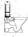
Fig. 1 is a cross-sectional view of a WC suite according to an embodiment; -
Fig. 2 is a cross-sectional view of a WC suite according to an embodiment; and -
Figs. 3a-b each shows a cross-sectional view of parts of a WC suite according to an embodiment directly after a flush has been initiated. - The following description focuses on embodiments of the present invention applicable to a WC suit.
- In an embodiment according to
Fig. 1 , aflushing system 10 for flushing water into aWC bowl 40 of aWC suit 100 is shown. Theflushing system 10 is constructed to allow a user of an associatedWC suit 100 to flush the toilet after use, and for this purpose theflushing system 10, and hence theWC suite 100, includes awater cistern 20 and a flushing mechanism 30. Thewater cistern 20 is in fluid communication with theWC bowl 40 by means of anoutlet 12 being controlled to open by means of the flushing mechanism 30. - The
water cistern 20 is capable of storing water between flushes and is in fluid communication with theWC bowl 40 by means of theoutlet 12 being controlled to open by means of the flushing mechanism 30. - The flushing mechanism 30 is constructed to open and close the
outlet 12 when the user operates a flush initiation means, such as apush button 32 arranged at the upper end of thewater cistern 20. When pressing theflush button 32, theoutlet 12 will open, i.e. it will be in fluid communication with thewater cistern 20, to allow the water enclosed within thewater cistern 20 to drain out from theoutlet 12 and into theWC bowl 40. After passing theoutlet 12, the water will pass through aflow path 14 which guides the flushing water through anopening 42 leading into theWC bowl 40. Theflow path 14 extends between theoutlet 12 of thewater cistern 20 and aninlet 48 of theWC bowl 40. - The
WC bowl 40 is constructed with abend 44 creating an integrated water trap in order to eliminate or at least reduce odours gases that are allowed to flow from asewer pipe 46, into theWC bowl 40 and further into the surrounding bathroom. After the flushing water has passed thebend 44, the water is led out from theWC bowl 40 into thesewer pipe 46. - During a flush, most of the water released from the
cistern 20 will flow from theoutlet 12 through thebend 44 of theWC bowl 40 into thesewer pipe 46. However, some of the water will, when it passes theflow path 14, hit the inlet 48 (such as a rim or a flow distributor device) of theWC bowl 40 which will cause a change in the water flow. The water will flow back, since it bounces at theinlet 48, into aflush box 50 arranged in fluid communication with theflow path 14. Theflush box 50 is an enclosure, or compartment, where water will accumulate during flushes. In prior art system, once theflush box 50 is filled with water, the water will eventually start to flow back into theWC bowl 40 due to thetilted flow path 14 from theflush box 50 to theinlet 48 of theWC bowl 40. Hence,many WC suites 100 will suffer from slow water trickles after a completed flush due to the arrangement of theflush box 50. This is a rather unpleasant feature since the water droplets create stains and lime deposits on the back of theWC bowl 40. - The inventors of the present invention have realized, after inventive and insightful reasoning that by arranging a
water trap 56 in theflush box 50 and arranging theflush box 50 to be in fluid communication with thesewer pipe 46 the above mentioned problems will be greatly reduced. Instead of having water trickling for several minutes, the water dropping has now been reduced to merely a few seconds. The reduction of the amount of water trickling thus greatly reduces the risks of stains in thetoilet bowl 40. - As seen in
Fig. 2 , theflush box 50 comprises twoopposite side walls bottom surface 57 forming an enclosure. It should be realized that additional side walls are also provided, however they are not shown. Theflush box 50 further comprises a dividingwall 52 which extends downwards into theflush box 50, but not entirely to the bottom of theflush box 50. The dividingwall 52 forms part of thewater trap 56. Thewater trap 56 may thus be in the form of a U-bend or N-shaped structure, formed by theside walls bottom surface 57 as well as the dividingwall 52. - The height of the water enclosed in the
water trap 56 may be between 30 and 70 mm, and more preferably around 50 mm. The height of the enclosed water is determined by the height of the twoside walls - In the
back wall 58 of the flush box anorifice 54 is arranged in order to connect theflush box 40 to thesewer pipe 46. Theflush box 50 is thus in direct fluid communication with thesewer pipe 46 by means of theorifice 54. Theflush box 50 is aligned with thesewer pipe 46 along a vertical line, so that when theflush box 50 fills up during a flush, the water will flow through theorifice 54 vertically down towards thesewer pipe 46. - The
flush box 50 and itswater trap 56 are preferably constructed by ceramic or other durable materials. In one embodiment theflush box 50 and theWC bowl 40 are constructed by the same material. Theflush box 50 and itswater trap 56 may be an integrated structure with the rest of theWC bowl 40. Thewater trap 56 is thus formed simultaneously with the rest of theWC bowl 40 which greatly reduces manufacturing costs. -
Fig. 3a shows an exemplified situation where thewater trap 56 of theflush box 50 starts to fill up with water just after a flush has occurred. The water which bounces at theinlet 48 of theWC bowl 40 will be lead into theflow path 14 leading to theflush box 50 and thewater trap 56. - In order to further reduce the water trickle the
flow path 14 is tilted so as to guide the water towards thewater trap 56. This restricts the direction of the water flow after a flush. Theinlet 48 of theWC bowl 40 is arranged at a higher level compared to theflush box 50, which creates a tiltedflow path 14. Theflow path 14 is tilted so that the highest point is arranged near theinlet 48 of theWC bowl 40 and the lowest point is arranged near thewater trap 56 of theflush box 50. Theflow path 14 is thus tilted upwards. The flushing water will flow in a direction downwards, while bouncing back from theinlet 48 towards theflush box 50. -
Fig. 3b shows the situation where theflush box 50 is fully filed with water. The remaining water in theflush box 50 will flow out through theorifice 54 down towards thesewer pipe 46. The water will thus not be dripping on the toilet bowl, but will instead be lead through thewater trap 56 into thesewer pipe 46. - The WC suits 100 shown in
Fig. 1-3 are of a rimless design i.e. theinlet 48 of theWC bowl 40 is not a rim. In a rimless WC suit theinlet 48, or flow distributor device, may be a single lip. The lip is arranged at the back of the upper part of thetoilet bowl 40 and releases the flushing water from thecistern 20 into theWC bowl 40. However it should be noted that the following description also is applicable for a WC suitehaving a flow distributor device such as a rim. - In one embodiment the
WC suit 100 is of a rimless design. Having a rimless design eliminates the possibility to arrange a water distributor in the WC suite 100 (since it normally is arranged under the rim of the WC suit 100) in order to reduce the problems of water trickles. The present invention is thus particularly useful for toilets being of a rimless design. - Although the present invention has been described above with reference to specific embodiments, it is not intended to be limited to the specific form set forth herein. Rather, the invention is limited only by the accompanying claims and, other embodiments than the specific above are equally possible within the scope of these appended claims.
Claims (8)
- A WC suite, comprising a water cistern (20), a WC bowl (40), and a flow path (14) extending between an outlet (12) of the water cistern (20) and an inlet (48) of the WC bowl (40) for guiding flushing water during a flush, said WC suite further comprising a flush box (50) arranged in fluid communication with said flow path (14) such that flushing water bouncing at the inlet (48) of the WC bowl (40) will accumulate therein,
characterized in that the flush box (50) is in fluid communication with a sewer pipe (46) connected to an outlet (12) of the WC bowl (40), wherein said flush box (50) is provided with a water trap (56). - The WC suite according to claim 1, wherein the flush box (50) is aligned with the sewer pipe (46) along a vertical line.
- The WC suite according to claim 1 or 2, wherein the flush box (50) is in fluid communication with the sewer pipe (46) by means of an orifice (54) provided in a wall (58) of said flush box (50).
- The WC suite according to any one of the preceding claims, wherein said flush box (50) comprises a dividing wall (52) extending downwards into said flush box (50), said dividing wall (52) forming part of said water trap (56),
- The WC suite according to any one of the preceding claims, wherein said flow path (14) extending between the flush box (50) and the inlet (12) of the WC bowl (40) is tilted upwards.
- The WC suite according to any of the preceding claims, wherein said flush box (50) comprises ceramic.
- The WC suite according to any of the preceding claims, wherein said flush box (50) is integrated with the WC bowl (40).
- The WC suite according to any of the preceding claims, wherein said flush box (50) and said WC bowl (40) comprises the same material.
Priority Applications (5)
| Application Number | Priority Date | Filing Date | Title |
|---|---|---|---|
| EP16160720.5A EP3219863B1 (en) | 2016-03-16 | 2016-03-16 | A wc suite |
| LTEP16160720.5T LT3219863T (en) | 2016-03-16 | 2016-03-16 | A wc suite |
| DK16160720.5T DK3219863T3 (en) | 2016-03-16 | 2016-03-16 | COMBINATION CLOSE |
| RU2017108641A RU2742827C2 (en) | 2016-03-16 | 2017-03-15 | Bathroom set |
| AU2017201777A AU2017201777B2 (en) | 2016-03-16 | 2017-03-15 | A WC Suite |
Applications Claiming Priority (1)
| Application Number | Priority Date | Filing Date | Title |
|---|---|---|---|
| EP16160720.5A EP3219863B1 (en) | 2016-03-16 | 2016-03-16 | A wc suite |
Publications (2)
| Publication Number | Publication Date |
|---|---|
| EP3219863A1 true EP3219863A1 (en) | 2017-09-20 |
| EP3219863B1 EP3219863B1 (en) | 2022-03-02 |
Family
ID=55542522
Family Applications (1)
| Application Number | Title | Priority Date | Filing Date |
|---|---|---|---|
| EP16160720.5A Active EP3219863B1 (en) | 2016-03-16 | 2016-03-16 | A wc suite |
Country Status (5)
| Country | Link |
|---|---|
| EP (1) | EP3219863B1 (en) |
| AU (1) | AU2017201777B2 (en) |
| DK (1) | DK3219863T3 (en) |
| LT (1) | LT3219863T (en) |
| RU (1) | RU2742827C2 (en) |
Cited By (1)
| Publication number | Priority date | Publication date | Assignee | Title |
|---|---|---|---|---|
| ES2922153A1 (en) * | 2021-02-25 | 2022-09-09 | Roca Sanitario Sa | TOILET (Machine-translation by Google Translate, not legally binding) |
Citations (7)
| Publication number | Priority date | Publication date | Assignee | Title |
|---|---|---|---|---|
| CH10222A (en) * | 1895-03-13 | 1895-10-31 | Schnitzler J B | Toilet |
| US3262132A (en) * | 1966-07-26 | Composite commode and overflow trough | ||
| US4028747A (en) * | 1976-03-26 | 1977-06-14 | Monogram Industries, Inc. | Oil toilet |
| US5803114A (en) * | 1994-07-25 | 1998-09-08 | American Standard Inc. | Back jet flush toilet systems and methods |
| US8151377B2 (en) * | 2007-08-12 | 2012-04-10 | Ronald Ferrell Pickle | Odorless and overflow-less toilet system |
| WO2014066187A1 (en) * | 2012-10-23 | 2014-05-01 | Stack Patrick Gerard | Anti-overflow toilet and method |
| US20160047113A1 (en) * | 2014-08-12 | 2016-02-18 | Lawrence Orubor | Toilet with Flushable Overflow Drain |
Family Cites Families (1)
| Publication number | Priority date | Publication date | Assignee | Title |
|---|---|---|---|---|
| RU89547U1 (en) * | 2009-07-07 | 2009-12-10 | Олег Евгеньевич Ивашков | TOILET BOWL |
-
2016
- 2016-03-16 EP EP16160720.5A patent/EP3219863B1/en active Active
- 2016-03-16 LT LTEP16160720.5T patent/LT3219863T/en unknown
- 2016-03-16 DK DK16160720.5T patent/DK3219863T3/en active
-
2017
- 2017-03-15 RU RU2017108641A patent/RU2742827C2/en active
- 2017-03-15 AU AU2017201777A patent/AU2017201777B2/en active Active
Patent Citations (7)
| Publication number | Priority date | Publication date | Assignee | Title |
|---|---|---|---|---|
| US3262132A (en) * | 1966-07-26 | Composite commode and overflow trough | ||
| CH10222A (en) * | 1895-03-13 | 1895-10-31 | Schnitzler J B | Toilet |
| US4028747A (en) * | 1976-03-26 | 1977-06-14 | Monogram Industries, Inc. | Oil toilet |
| US5803114A (en) * | 1994-07-25 | 1998-09-08 | American Standard Inc. | Back jet flush toilet systems and methods |
| US8151377B2 (en) * | 2007-08-12 | 2012-04-10 | Ronald Ferrell Pickle | Odorless and overflow-less toilet system |
| WO2014066187A1 (en) * | 2012-10-23 | 2014-05-01 | Stack Patrick Gerard | Anti-overflow toilet and method |
| US20160047113A1 (en) * | 2014-08-12 | 2016-02-18 | Lawrence Orubor | Toilet with Flushable Overflow Drain |
Cited By (1)
| Publication number | Priority date | Publication date | Assignee | Title |
|---|---|---|---|---|
| ES2922153A1 (en) * | 2021-02-25 | 2022-09-09 | Roca Sanitario Sa | TOILET (Machine-translation by Google Translate, not legally binding) |
Also Published As
| Publication number | Publication date |
|---|---|
| RU2017108641A (en) | 2018-09-17 |
| DK3219863T3 (en) | 2022-05-23 |
| LT3219863T (en) | 2022-05-10 |
| AU2017201777A1 (en) | 2017-10-05 |
| RU2742827C2 (en) | 2021-02-11 |
| EP3219863B1 (en) | 2022-03-02 |
| AU2017201777B2 (en) | 2022-02-17 |
| RU2017108641A3 (en) | 2020-06-19 |
Similar Documents
| Publication | Publication Date | Title |
|---|---|---|
| CN100482904C (en) | Flush toilet bowl | |
| CN112923117B (en) | Fill valve system | |
| KR100674797B1 (en) | High performance flush valve assembly | |
| HUT70905A (en) | Wc flushing device | |
| JP2010531399A (en) | Western-style toilet with an overflow prevention auxiliary tank | |
| CN104812971B (en) | Anti-overflow toilet and method | |
| JP2023032964A (en) | Washing water tank device and water closet device comprising the same | |
| EA039580B1 (en) | Device for toilets | |
| EP2696003A1 (en) | Flush tank service liquid dispenser device | |
| US6131211A (en) | Low profile vacuum toilet | |
| AU2017201777B2 (en) | A WC Suite | |
| JP6908871B2 (en) | Washing toilet bowl | |
| AU5008001A (en) | Suction-type siphon for a flushing device | |
| JP5412779B2 (en) | Western-style toilet | |
| JP5821082B2 (en) | Water supply device for washing tank | |
| EP3553236A1 (en) | Water seal device for removing odour of toilet | |
| US5666675A (en) | Flushing means with a toilet bowl | |
| JP5441015B2 (en) | Washing water tank device | |
| US8117687B2 (en) | Diverter valve with minimum bias forces | |
| JP2001279796A (en) | Flush toilet and drain socket | |
| KR200480074Y1 (en) | Cleaner discharger for toilet bowl | |
| JP6620397B2 (en) | Urinal equipment | |
| JP4411737B2 (en) | Washing water discharge method of flush toilet | |
| JP2006291451A (en) | Flush closet bowl | |
| EP2592193A1 (en) | Dosing device of a service liquid for a flushing tank, and flushing tank provided with said device |
Legal Events
| Date | Code | Title | Description |
|---|---|---|---|
| PUAI | Public reference made under article 153(3) epc to a published international application that has entered the european phase |
Free format text: ORIGINAL CODE: 0009012 |
|
| STAA | Information on the status of an ep patent application or granted ep patent |
Free format text: STATUS: THE APPLICATION HAS BEEN PUBLISHED |
|
| AK | Designated contracting states |
Kind code of ref document: A1 Designated state(s): AL AT BE BG CH CY CZ DE DK EE ES FI FR GB GR HR HU IE IS IT LI LT LU LV MC MK MT NL NO PL PT RO RS SE SI SK SM TR |
|
| AX | Request for extension of the european patent |
Extension state: BA ME |
|
| STAA | Information on the status of an ep patent application or granted ep patent |
Free format text: STATUS: REQUEST FOR EXAMINATION WAS MADE |
|
| 17P | Request for examination filed |
Effective date: 20180320 |
|
| RBV | Designated contracting states (corrected) |
Designated state(s): AL AT BE BG CH CY CZ DE DK EE ES FI FR GB GR HR HU IE IS IT LI LT LU LV MC MK MT NL NO PL PT RO RS SE SI SK SM TR |
|
| STAA | Information on the status of an ep patent application or granted ep patent |
Free format text: STATUS: EXAMINATION IS IN PROGRESS |
|
| 17Q | First examination report despatched |
Effective date: 20191024 |
|
| GRAP | Despatch of communication of intention to grant a patent |
Free format text: ORIGINAL CODE: EPIDOSNIGR1 |
|
| STAA | Information on the status of an ep patent application or granted ep patent |
Free format text: STATUS: GRANT OF PATENT IS INTENDED |
|
| INTG | Intention to grant announced |
Effective date: 20211007 |
|
| GRAS | Grant fee paid |
Free format text: ORIGINAL CODE: EPIDOSNIGR3 |
|
| GRAA | (expected) grant |
Free format text: ORIGINAL CODE: 0009210 |
|
| STAA | Information on the status of an ep patent application or granted ep patent |
Free format text: STATUS: THE PATENT HAS BEEN GRANTED |
|
| AK | Designated contracting states |
Kind code of ref document: B1 Designated state(s): AL AT BE BG CH CY CZ DE DK EE ES FI FR GB GR HR HU IE IS IT LI LT LU LV MC MK MT NL NO PL PT RO RS SE SI SK SM TR |
|
| REG | Reference to a national code |
Ref country code: GB Ref legal event code: FG4D |
|
| REG | Reference to a national code |
Ref country code: CH Ref legal event code: EP Ref country code: AT Ref legal event code: REF Ref document number: 1472338 Country of ref document: AT Kind code of ref document: T Effective date: 20220315 |
|
| REG | Reference to a national code |
Ref country code: DE Ref legal event code: R096 Ref document number: 602016069516 Country of ref document: DE |
|
| REG | Reference to a national code |
Ref country code: IE Ref legal event code: FG4D |
|
| REG | Reference to a national code |
Ref country code: FI Ref legal event code: FGE |
|
| REG | Reference to a national code |
Ref country code: DK Ref legal event code: T3 Effective date: 20220517 |
|
| REG | Reference to a national code |
Ref country code: NO Ref legal event code: T2 Effective date: 20220302 |
|
| REG | Reference to a national code |
Ref country code: SE Ref legal event code: TRGR |
|
| REG | Reference to a national code |
Ref country code: NL Ref legal event code: MP Effective date: 20220302 |
|
| REG | Reference to a national code |
Ref country code: EE Ref legal event code: FG4A Ref document number: E022349 Country of ref document: EE Effective date: 20220517 |
|
| PG25 | Lapsed in a contracting state [announced via postgrant information from national office to epo] |
Ref country code: RS Free format text: LAPSE BECAUSE OF FAILURE TO SUBMIT A TRANSLATION OF THE DESCRIPTION OR TO PAY THE FEE WITHIN THE PRESCRIBED TIME-LIMIT Effective date: 20220302 Ref country code: HR Free format text: LAPSE BECAUSE OF FAILURE TO SUBMIT A TRANSLATION OF THE DESCRIPTION OR TO PAY THE FEE WITHIN THE PRESCRIBED TIME-LIMIT Effective date: 20220302 Ref country code: ES Free format text: LAPSE BECAUSE OF FAILURE TO SUBMIT A TRANSLATION OF THE DESCRIPTION OR TO PAY THE FEE WITHIN THE PRESCRIBED TIME-LIMIT Effective date: 20220302 Ref country code: BG Free format text: LAPSE BECAUSE OF FAILURE TO SUBMIT A TRANSLATION OF THE DESCRIPTION OR TO PAY THE FEE WITHIN THE PRESCRIBED TIME-LIMIT Effective date: 20220602 |
|
| REG | Reference to a national code |
Ref country code: AT Ref legal event code: MK05 Ref document number: 1472338 Country of ref document: AT Kind code of ref document: T Effective date: 20220302 |
|
| PG25 | Lapsed in a contracting state [announced via postgrant information from national office to epo] |
Ref country code: PL Free format text: LAPSE BECAUSE OF FAILURE TO SUBMIT A TRANSLATION OF THE DESCRIPTION OR TO PAY THE FEE WITHIN THE PRESCRIBED TIME-LIMIT Effective date: 20220302 Ref country code: GR Free format text: LAPSE BECAUSE OF FAILURE TO SUBMIT A TRANSLATION OF THE DESCRIPTION OR TO PAY THE FEE WITHIN THE PRESCRIBED TIME-LIMIT Effective date: 20220603 |
|
| PG25 | Lapsed in a contracting state [announced via postgrant information from national office to epo] |
Ref country code: NL Free format text: LAPSE BECAUSE OF FAILURE TO SUBMIT A TRANSLATION OF THE DESCRIPTION OR TO PAY THE FEE WITHIN THE PRESCRIBED TIME-LIMIT Effective date: 20220302 |
|
| REG | Reference to a national code |
Ref country code: DE Ref legal event code: R119 Ref document number: 602016069516 Country of ref document: DE |
|
| PG25 | Lapsed in a contracting state [announced via postgrant information from national office to epo] |
Ref country code: SM Free format text: LAPSE BECAUSE OF FAILURE TO SUBMIT A TRANSLATION OF THE DESCRIPTION OR TO PAY THE FEE WITHIN THE PRESCRIBED TIME-LIMIT Effective date: 20220302 Ref country code: SK Free format text: LAPSE BECAUSE OF FAILURE TO SUBMIT A TRANSLATION OF THE DESCRIPTION OR TO PAY THE FEE WITHIN THE PRESCRIBED TIME-LIMIT Effective date: 20220302 Ref country code: RO Free format text: LAPSE BECAUSE OF FAILURE TO SUBMIT A TRANSLATION OF THE DESCRIPTION OR TO PAY THE FEE WITHIN THE PRESCRIBED TIME-LIMIT Effective date: 20220302 Ref country code: PT Free format text: LAPSE BECAUSE OF FAILURE TO SUBMIT A TRANSLATION OF THE DESCRIPTION OR TO PAY THE FEE WITHIN THE PRESCRIBED TIME-LIMIT Effective date: 20220704 Ref country code: CZ Free format text: LAPSE BECAUSE OF FAILURE TO SUBMIT A TRANSLATION OF THE DESCRIPTION OR TO PAY THE FEE WITHIN THE PRESCRIBED TIME-LIMIT Effective date: 20220302 Ref country code: AT Free format text: LAPSE BECAUSE OF FAILURE TO SUBMIT A TRANSLATION OF THE DESCRIPTION OR TO PAY THE FEE WITHIN THE PRESCRIBED TIME-LIMIT Effective date: 20220302 |
|
| REG | Reference to a national code |
Ref country code: CH Ref legal event code: PL |
|
| PG25 | Lapsed in a contracting state [announced via postgrant information from national office to epo] |
Ref country code: IS Free format text: LAPSE BECAUSE OF FAILURE TO SUBMIT A TRANSLATION OF THE DESCRIPTION OR TO PAY THE FEE WITHIN THE PRESCRIBED TIME-LIMIT Effective date: 20220702 Ref country code: AL Free format text: LAPSE BECAUSE OF FAILURE TO SUBMIT A TRANSLATION OF THE DESCRIPTION OR TO PAY THE FEE WITHIN THE PRESCRIBED TIME-LIMIT Effective date: 20220302 |
|
| REG | Reference to a national code |
Ref country code: BE Ref legal event code: MM Effective date: 20220331 |
|
| PLBE | No opposition filed within time limit |
Free format text: ORIGINAL CODE: 0009261 |
|
| STAA | Information on the status of an ep patent application or granted ep patent |
Free format text: STATUS: NO OPPOSITION FILED WITHIN TIME LIMIT |
|
| PG25 | Lapsed in a contracting state [announced via postgrant information from national office to epo] |
Ref country code: MC Free format text: LAPSE BECAUSE OF FAILURE TO SUBMIT A TRANSLATION OF THE DESCRIPTION OR TO PAY THE FEE WITHIN THE PRESCRIBED TIME-LIMIT Effective date: 20220302 Ref country code: LU Free format text: LAPSE BECAUSE OF NON-PAYMENT OF DUE FEES Effective date: 20220316 Ref country code: LI Free format text: LAPSE BECAUSE OF NON-PAYMENT OF DUE FEES Effective date: 20220331 Ref country code: IE Free format text: LAPSE BECAUSE OF NON-PAYMENT OF DUE FEES Effective date: 20220316 Ref country code: FR Free format text: LAPSE BECAUSE OF NON-PAYMENT OF DUE FEES Effective date: 20220502 Ref country code: DE Free format text: LAPSE BECAUSE OF NON-PAYMENT OF DUE FEES Effective date: 20221001 Ref country code: CH Free format text: LAPSE BECAUSE OF NON-PAYMENT OF DUE FEES Effective date: 20220331 |
|
| 26N | No opposition filed |
Effective date: 20221205 |
|
| PG25 | Lapsed in a contracting state [announced via postgrant information from national office to epo] |
Ref country code: SI Free format text: LAPSE BECAUSE OF FAILURE TO SUBMIT A TRANSLATION OF THE DESCRIPTION OR TO PAY THE FEE WITHIN THE PRESCRIBED TIME-LIMIT Effective date: 20220302 Ref country code: BE Free format text: LAPSE BECAUSE OF NON-PAYMENT OF DUE FEES Effective date: 20220331 |
|
| GBPC | Gb: european patent ceased through non-payment of renewal fee |
Effective date: 20220602 |
|
| PG25 | Lapsed in a contracting state [announced via postgrant information from national office to epo] |
Ref country code: GB Free format text: LAPSE BECAUSE OF NON-PAYMENT OF DUE FEES Effective date: 20220602 |
|
| P01 | Opt-out of the competence of the unified patent court (upc) registered |
Effective date: 20230527 |
|
| PG25 | Lapsed in a contracting state [announced via postgrant information from national office to epo] |
Ref country code: IT Free format text: LAPSE BECAUSE OF FAILURE TO SUBMIT A TRANSLATION OF THE DESCRIPTION OR TO PAY THE FEE WITHIN THE PRESCRIBED TIME-LIMIT Effective date: 20220302 |
|
| PG25 | Lapsed in a contracting state [announced via postgrant information from national office to epo] |
Ref country code: HU Free format text: LAPSE BECAUSE OF FAILURE TO SUBMIT A TRANSLATION OF THE DESCRIPTION OR TO PAY THE FEE WITHIN THE PRESCRIBED TIME-LIMIT; INVALID AB INITIO Effective date: 20160316 |
|
| PG25 | Lapsed in a contracting state [announced via postgrant information from national office to epo] |
Ref country code: MK Free format text: LAPSE BECAUSE OF FAILURE TO SUBMIT A TRANSLATION OF THE DESCRIPTION OR TO PAY THE FEE WITHIN THE PRESCRIBED TIME-LIMIT Effective date: 20220302 Ref country code: CY Free format text: LAPSE BECAUSE OF FAILURE TO SUBMIT A TRANSLATION OF THE DESCRIPTION OR TO PAY THE FEE WITHIN THE PRESCRIBED TIME-LIMIT Effective date: 20220302 |
|
| PGFP | Annual fee paid to national office [announced via postgrant information from national office to epo] |
Ref country code: LV Payment date: 20240212 Year of fee payment: 9 |
|
| PG25 | Lapsed in a contracting state [announced via postgrant information from national office to epo] |
Ref country code: MT Free format text: LAPSE BECAUSE OF FAILURE TO SUBMIT A TRANSLATION OF THE DESCRIPTION OR TO PAY THE FEE WITHIN THE PRESCRIBED TIME-LIMIT Effective date: 20220302 |
|
| PG25 | Lapsed in a contracting state [announced via postgrant information from national office to epo] |
Ref country code: LV Free format text: LAPSE BECAUSE OF NON-PAYMENT OF DUE FEES Effective date: 20250316 |
|
| PG25 | Lapsed in a contracting state [announced via postgrant information from national office to epo] |
Ref country code: TR Free format text: LAPSE BECAUSE OF FAILURE TO SUBMIT A TRANSLATION OF THE DESCRIPTION OR TO PAY THE FEE WITHIN THE PRESCRIBED TIME-LIMIT Effective date: 20220302 |
|
| PGFP | Annual fee paid to national office [announced via postgrant information from national office to epo] |
Ref country code: SE Payment date: 20260317 Year of fee payment: 11 |
|
| PGFP | Annual fee paid to national office [announced via postgrant information from national office to epo] |
Ref country code: LT Payment date: 20260226 Year of fee payment: 11 |
|
| PGFP | Annual fee paid to national office [announced via postgrant information from national office to epo] |
Ref country code: NO Payment date: 20260312 Year of fee payment: 11 Ref country code: DK Payment date: 20260311 Year of fee payment: 11 |
|
| PGFP | Annual fee paid to national office [announced via postgrant information from national office to epo] |
Ref country code: FI Payment date: 20260310 Year of fee payment: 11 |
|
| PGFP | Annual fee paid to national office [announced via postgrant information from national office to epo] |
Ref country code: EE Payment date: 20260227 Year of fee payment: 11 |