EP3219626A1 - Method and apparatus for leak detection for packages - Google Patents
Method and apparatus for leak detection for packages Download PDFInfo
- Publication number
- EP3219626A1 EP3219626A1 EP16161147.0A EP16161147A EP3219626A1 EP 3219626 A1 EP3219626 A1 EP 3219626A1 EP 16161147 A EP16161147 A EP 16161147A EP 3219626 A1 EP3219626 A1 EP 3219626A1
- Authority
- EP
- European Patent Office
- Prior art keywords
- packages
- gas
- leak
- package
- production line
- Prior art date
- Legal status (The legal status is an assumption and is not a legal conclusion. Google has not performed a legal analysis and makes no representation as to the accuracy of the status listed.)
- Granted
Links
Images
Classifications
-
- B—PERFORMING OPERATIONS; TRANSPORTING
- B65—CONVEYING; PACKING; STORING; HANDLING THIN OR FILAMENTARY MATERIAL
- B65B—MACHINES, APPARATUS OR DEVICES FOR, OR METHODS OF, PACKAGING ARTICLES OR MATERIALS; UNPACKING
- B65B9/00—Enclosing successive articles, or quantities of material, e.g. liquids or semiliquids, in flat, folded, or tubular webs of flexible sheet material; Subdividing filled flexible tubes to form packages
-
- B—PERFORMING OPERATIONS; TRANSPORTING
- B25—HAND TOOLS; PORTABLE POWER-DRIVEN TOOLS; MANIPULATORS
- B25J—MANIPULATORS; CHAMBERS PROVIDED WITH MANIPULATION DEVICES
- B25J11/00—Manipulators not otherwise provided for
- B25J11/0045—Manipulators used in the food industry
-
- B—PERFORMING OPERATIONS; TRANSPORTING
- B25—HAND TOOLS; PORTABLE POWER-DRIVEN TOOLS; MANIPULATORS
- B25J—MANIPULATORS; CHAMBERS PROVIDED WITH MANIPULATION DEVICES
- B25J9/00—Program-controlled manipulators
- B25J9/0093—Program-controlled manipulators co-operating with conveyor means
-
- B—PERFORMING OPERATIONS; TRANSPORTING
- B65—CONVEYING; PACKING; STORING; HANDLING THIN OR FILAMENTARY MATERIAL
- B65B—MACHINES, APPARATUS OR DEVICES FOR, OR METHODS OF, PACKAGING ARTICLES OR MATERIALS; UNPACKING
- B65B31/00—Packaging articles or materials under special atmospheric or gaseous conditions; Adding propellants to aerosol containers
-
- B—PERFORMING OPERATIONS; TRANSPORTING
- B65—CONVEYING; PACKING; STORING; HANDLING THIN OR FILAMENTARY MATERIAL
- B65B—MACHINES, APPARATUS OR DEVICES FOR, OR METHODS OF, PACKAGING ARTICLES OR MATERIALS; UNPACKING
- B65B57/00—Automatic control, checking, warning, or safety devices
- B65B57/10—Automatic control, checking, warning, or safety devices responsive to absence, presence, abnormal feed, or misplacement of articles or materials to be packaged
-
- B—PERFORMING OPERATIONS; TRANSPORTING
- B65—CONVEYING; PACKING; STORING; HANDLING THIN OR FILAMENTARY MATERIAL
- B65B—MACHINES, APPARATUS OR DEVICES FOR, OR METHODS OF, PACKAGING ARTICLES OR MATERIALS; UNPACKING
- B65B57/00—Automatic control, checking, warning, or safety devices
- B65B57/18—Automatic control, checking, warning, or safety devices causing operation of audible or visible alarm signals
-
- B—PERFORMING OPERATIONS; TRANSPORTING
- B65—CONVEYING; PACKING; STORING; HANDLING THIN OR FILAMENTARY MATERIAL
- B65B—MACHINES, APPARATUS OR DEVICES FOR, OR METHODS OF, PACKAGING ARTICLES OR MATERIALS; UNPACKING
- B65B61/00—Auxiliary devices, not otherwise provided for, for operating on sheets, blanks, webs, binding material, containers or packages
- B65B61/28—Auxiliary devices, not otherwise provided for, for operating on sheets, blanks, webs, binding material, containers or packages for discharging completed packages from machines
-
- G—PHYSICS
- G01—MEASURING; TESTING
- G01M—TESTING STATIC OR DYNAMIC BALANCE OF MACHINES OR STRUCTURES; TESTING OF STRUCTURES OR APPARATUS, NOT OTHERWISE PROVIDED FOR
- G01M3/00—Investigating fluid-tightness of structures
- G01M3/02—Investigating fluid-tightness of structures by using fluid or vacuum
- G01M3/04—Investigating fluid-tightness of structures by using fluid or vacuum by detecting the presence of fluid at the leakage point
- G01M3/20—Investigating fluid-tightness of structures by using fluid or vacuum by detecting the presence of fluid at the leakage point using special tracer materials, e.g. dye, fluorescent material, radioactive material
- G01M3/202—Investigating fluid-tightness of structures by using fluid or vacuum by detecting the presence of fluid at the leakage point using special tracer materials, e.g. dye, fluorescent material, radioactive material using mass spectrometer detection systems
- G01M3/205—Accessories or associated equipment; Pump constructions
-
- G—PHYSICS
- G01—MEASURING; TESTING
- G01M—TESTING STATIC OR DYNAMIC BALANCE OF MACHINES OR STRUCTURES; TESTING OF STRUCTURES OR APPARATUS, NOT OTHERWISE PROVIDED FOR
- G01M3/00—Investigating fluid-tightness of structures
- G01M3/02—Investigating fluid-tightness of structures by using fluid or vacuum
- G01M3/04—Investigating fluid-tightness of structures by using fluid or vacuum by detecting the presence of fluid at the leakage point
- G01M3/20—Investigating fluid-tightness of structures by using fluid or vacuum by detecting the presence of fluid at the leakage point using special tracer materials, e.g. dye, fluorescent material, radioactive material
- G01M3/22—Investigating fluid-tightness of structures by using fluid or vacuum by detecting the presence of fluid at the leakage point using special tracer materials, e.g. dye, fluorescent material, radioactive material for pipes, cables or tubes; for pipe joints or seals; for valves; for welds; for containers, e.g. radiators
- G01M3/226—Investigating fluid-tightness of structures by using fluid or vacuum by detecting the presence of fluid at the leakage point using special tracer materials, e.g. dye, fluorescent material, radioactive material for pipes, cables or tubes; for pipe joints or seals; for valves; for welds; for containers, e.g. radiators for containers, e.g. radiators
- G01M3/227—Investigating fluid-tightness of structures by using fluid or vacuum by detecting the presence of fluid at the leakage point using special tracer materials, e.g. dye, fluorescent material, radioactive material for pipes, cables or tubes; for pipe joints or seals; for valves; for welds; for containers, e.g. radiators for containers, e.g. radiators for flexible or elastic containers
-
- B—PERFORMING OPERATIONS; TRANSPORTING
- B65—CONVEYING; PACKING; STORING; HANDLING THIN OR FILAMENTARY MATERIAL
- B65B—MACHINES, APPARATUS OR DEVICES FOR, OR METHODS OF, PACKAGING ARTICLES OR MATERIALS; UNPACKING
- B65B25/00—Packaging other articles presenting special problems
- B65B25/001—Packaging other articles presenting special problems of foodstuffs, combined with their conservation
-
- B—PERFORMING OPERATIONS; TRANSPORTING
- B65—CONVEYING; PACKING; STORING; HANDLING THIN OR FILAMENTARY MATERIAL
- B65B—MACHINES, APPARATUS OR DEVICES FOR, OR METHODS OF, PACKAGING ARTICLES OR MATERIALS; UNPACKING
- B65B51/00—Devices for, or methods of, sealing or securing package folds or closures; Devices for gathering or twisting wrappers, or necks of bags
- B65B51/02—Applying adhesives or sealing liquids
-
- B—PERFORMING OPERATIONS; TRANSPORTING
- B65—CONVEYING; PACKING; STORING; HANDLING THIN OR FILAMENTARY MATERIAL
- B65B—MACHINES, APPARATUS OR DEVICES FOR, OR METHODS OF, PACKAGING ARTICLES OR MATERIALS; UNPACKING
- B65B51/00—Devices for, or methods of, sealing or securing package folds or closures; Devices for gathering or twisting wrappers, or necks of bags
- B65B51/10—Applying or generating heat or pressure or combinations thereof
-
- B—PERFORMING OPERATIONS; TRANSPORTING
- B65—CONVEYING; PACKING; STORING; HANDLING THIN OR FILAMENTARY MATERIAL
- B65B—MACHINES, APPARATUS OR DEVICES FOR, OR METHODS OF, PACKAGING ARTICLES OR MATERIALS; UNPACKING
- B65B59/00—Arrangements to enable machines to handle articles of different sizes, to produce packages of different sizes, to vary the contents of packages, to handle different types of packaging material, or to give access for cleaning or maintenance purposes
- B65B59/003—Arrangements to enable adjustments related to the packaging material
Definitions
- the present invention is directed to leak detection for packages, in particular for packages for food products like e. g. welded bags filled with food products.
- a further known approach for leak detection comprises a tracer gas (e.g. helium, carbon dioxide or hydrogen), which is added to the protective gas within the package.
- the tracer gas in contrast to the protective gas, can be detected easily by a respective detector.
- a potential gas flow through leaks is increased by exerting a manual pressure onto a package or by reducing the pressure in the environment of the package. Both can be done in an enclosed surrounding like a chamber, in which the concentration of the tracer gas is monitored.
- An increasing tracer gas concentration coinciding with exerting a pressure onto a package is an indication for a leak in this package.
- Prior approaches have the disadvantage of being time consuming. Often, only a small number of sample packages can be investigated. Surveying the entire production requires a more efficient leak detection. Further, it can only be detected that there is a leak in a package, whereas leaks cannot be located. The location, however, could be useful information, e. g., for fixing defects in the packaging process.
- an object of the present invention to overcome at least in part the disadvantages known from prior art, and, in particular, to provide a method and a production line for leak detection for packages with an increased efficiency.
- the method according to the present invention is directed to detecting leaks in packages processed in a production line comprising at least one leak detector having a robot arm with at least one gas detector.
- the method comprises at least the following steps:
- steps a) and b) are preferably, but not necessarily, performed in the given order.
- the packages are preferably tubular bags, other bags, wrappings, bowls with a foil cover or boxes, in which food products may be stored and/or sold to customers.
- the packages are preferably made at least partly with a synthetic material such as plastic, polyethylene, polyethyleneterephthalate (PET) and/or polypropylene (PP).
- the packages are made at least partly from a metal, in particular Aluminium.
- the packages are made from composite materials comprising e. g. fibrous materials, paper, cardboard or the like being at least coated with a metal and/or plastic such as polyethylene, polyethyleneterephthalate (PET) and/or polypropylene (PP).
- the materials preferably fulfill hygiene requirements that are relevant when using the packages for food products.
- the packages After being filled with the food products, the packages are preferably sealed by welding or gluing. Preferably, the packages are gastight after sealing. Further, it is preferred that a multitude of equal packages are processed together. This can facilitate the production process, in particular if the process is at least partly automatized.
- the production line preferably comprises all apparatuses necessary to fill the products into the packages, seal the packages and further process the packages, for example by storing the packages in boxes for transporting.
- the production line is operated at least partly automatically. That is, the production line may be controlled by a computer program product.
- the production line preferably comprises one or more robots and/or other automatically operable apparatuses. An automatized production may lower costs and increase the output quality.
- the at least one leak detector is installed for detecting leaks in the packages. This means, in particular, that packages with a leak may be identified. As contact with air, and particularly with oxygen, can cause food products to perish, a leak in a package can reduce the quality of the respective food product.
- the leak detector can be operated at least partly automatically. As described above, this can facilitate the production process, in particular the leak detection process to lower costs. Further, this way, the output of the production line, i.e. the number of packages produced and/or examined for leaks per given time interval, may be increased.
- the robot arm is controlled by a computer program product.
- the detection path, along which the robot arm moves the gas detector is predeterminedly implemented in the computer program product.
- the robot arm preferably comprises one or more rods which are connected to each other by junctions. This way, preferably, the robot arm can be used for moving the gas detector flexibly within a large space and along complex detection paths. Further, it is preferred that the gas detector is attached to the utmost tip of the robot arm.
- the gas detector is preferably installed for detecting a gas that may penetrate through a leak in a package. Thereby, leaky packages can be identified.
- the gas detector comprises a mass spectrometer, in which the constituents of detected gases can be identified. With such a mass spectrometer different detected gases can be distinguished.
- the method is performed for one package at a time. Alternatively, it is preferred that a multitude of packages are examined simultaneously.
- the detection path is predetermined depending on the number of packages intended to be examined at the same time. Further, the detection path is preferably adapted to the material, shape and/or size of the packages. Preferably, the detection path can be predetermined taking into consideration positions on the package with an increased probability for leaks. Preferably, the detection path is continuously adapted based on the data generated during the leak detection, e. g. considering the probability or absolute number of leaks in a predeterminable number of leak detection processes at a specific position of the package.
- the data in step a) comprises at preferably concentration values for of all detected gases.
- the data comprises position and/or movement data of the robot arm to allow in particular to correlate the concentration values with the position of the gas detector, in particular relative to the packages being controlled. If one of the detected concentrations is higher than a respectively preset threshold value, the examined package is deemed to be leaky in step b).
- the threshold values for the different gases are preferably preset depending on their concentration within the atmosphere inside the packages compared with their concentration in the environment of the packages, in particular in air.
- the packages are filled at least in part with a tracer gas detectable by the gas detector.
- the tracer gas preferably is a gas that can be detected easily by the gas detector.
- helium, carbon dioxide or hydrogen are preferred.
- the tracer gas complies with hygiene requirements relevant in the context of food products. That is, in particular, the tracer gas is preferably an inert gas and particularly does not comprise oxygen. It is further preferred that the tracer gas has a concentration in the range of 0.5 Vol.-% to 20 Vol.-% [volume percent], in particular in the range of 3 Vol.-% to 10 Vol.-%.
- the remainder of the package volume is preferably filled with an(other) inert gas, preferably nitrogen.
- step a) further comprises moving the gas detector along at least a part of at least one sealing patch of at least one of the packages.
- the sealing patches are areas, where the package was sealed and may be, in particular, welding seams or splices.
- the detection path preferably is arranged such that the gas detector is moved along the sealing patches. It is preferred that all sealing patches of a package are covered completely by the detection path.
- a further preferred embodiment of the method comprises marking a location of a leak on a leaky package.
- Knowing the location of a leak can be useful information for remedying a possible defect in the equipment used in the production process. Marking the location is preferably performed with a paint, an ink or a dye that is adapted to the surface properties of the package.
- the method further comprises the following step:
- this package is preferably excluded from further processing.
- This is preferably achieved by an ejector, which, for example, displaces a leaky package on or from a conveyer.
- the leaky package may then be conveyed to a separate area or collection means for leaky packages, such as a waste container.
- the ejector is operated by a computer program product, which has access to the information gained in step a).
- a leaky package is removed manually from the production line, e.g. by an operator.
- step b) a signal is emitted when a package is deemed to be leaky.
- the signal preferably is an optical and/or an acoustical signal. It is preferably triggered by a computer program product. It is further preferred that a computer program products records and stores data about the detected gas concentrations and particularly about detected leaks and about the position of the leaks relative to the package. Evaluating this data may be useful for identifying defects in the production line.
- the packages are conveyed continuously through the production line.
- the packages are moved or conveyed at a constant speed during leak detection.
- the robot arm basically adapts the speed of the conveyer the products are conveyed by, and further performs the motion necessary for gas detection relative to the motion of the packages.
- This embodiment of the method is advantageous because the production line as a whole may be operated independently of the leak detector. This means, particularly, that the production line does not have to be interrupted for every examination of a package.
- the packages are conveyed discontinuously through the production line.
- the packages do not move during leak detection.
- the duration of leak detection is adapted to a clock frequency, at which the production line as a whole is operated.
- the clock frequency denotes the frequency of the discontinuous conveying of the packages.
- the clock frequency itself can be correlated to the production frequency of the packages.
- a multitude of leak detectors is used to perform steps a) and b) for a multitude of packages simultaneously.
- the throughput of the production line can be increased by multiplying the number of packages examinable in each examination cycle. This can increase the efficiency and lower costs.
- the multitude of leak detectors can either be installed on different robot arms or on the same robot art.
- a multitude of gas detectors at the same robot arm is used to perform steps a) and b) for a multitude of packages simultaneously.
- the robot arm is installed for moving the multitude of gas detectors in a parallel way.
- a multitude of packages can be examined at the same time.
- a multitude of leak detectors can be used to examine a single package in a faster way.
- two gas detectors are used at the same robot arm. In that case, e.g., two sealing patches of the same package can be examined simultaneously by the same robot arm.
- each robot arm has a multitude of gas detectors each.
- a pressure is exerted onto the at least one of the packages (4) in step a).
- Increasing the pressure of the gas in the examined package can increase the rate at which gas penetrates a potential leak. This can facilitate leak detection.
- the pressure is preferably exerted manually by an operator.
- an apparatus such as a robot automatically presses a plate or a stamp onto the package, which is hold by a respective counterpart, e. g. by a stationary plate.
- a production line comprising at least:
- the production line is preferably installed to be operated according to the above described method according to the present invention.
- the details and advantages disclosed for the method of the invention can be applied to the production line according to the invention and vice versa.
- the robot arm can be moved with a multitude of degrees of freedom.
- the production line can be adapted to packages of various shapes and/or sizes. This may lower costs because the same production line, or at least the same leak detector, can be used for different products.
- the robot arm further comprises a marker for marking a location of a leak on a leaky package.
- the marker is installed to be operated according to the above described method for marking the location of a leak on a leaky package.
- the marker is preferably arranged at the utmost tip of the robot arm, so that it can be moved flexibly within a large space.
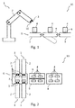
- a production line 11 that comprises a leak detector 1 having a robot arm 2 with a gas detector 3 and a marker 10 at its utmost tip.
- a conveyer 6 comprising a first section 7, a second section 8 and an ejector 9 in between the first section 7 and the second section 8 is used to convey packages 4 thereon.
- Each of the packages 4 has a welding seam 5. With the ejector 9, leaky packages 4 can be ejected from the conveyor 6 and from the production line 11.
- Fig. 2 shows a further embodiment of a production line 11 comprising a conveyer 6 having a first section 7, a second section 8 and a conveyer 9.
- the production line 11 further comprises four leak detectors 1.
- Each of the leak detectors 1 comprises a robot arm 2.
- Each robot arm 2 has two gas detectors 3.
- Packages 4 are arranged in two rows on the conveyer 6. Thereby, four packages 4 can be examined by the four leak detectors 1 simultaneously, wherein each package 4 is examined by two gas detectors 3. If a leak is detected in one of the packages 4, the ejector 9, which comprises two parts, can eject the respective package 4.
- the tracer gas can be detected by a gas detector 1 moved along the package by a robot arm. Compared with methods for a stationary gas detector, this method provides an improved efficiency because a dissipating of the tracer gas between test cycles does not have to be awaited.
Landscapes
- Engineering & Computer Science (AREA)
- Mechanical Engineering (AREA)
- Physics & Mathematics (AREA)
- General Physics & Mathematics (AREA)
- Robotics (AREA)
- Chemical & Material Sciences (AREA)
- Dispersion Chemistry (AREA)
- Life Sciences & Earth Sciences (AREA)
- Food Science & Technology (AREA)
- Examining Or Testing Airtightness (AREA)
Abstract
Description
- The present invention is directed to leak detection for packages, in particular for packages for food products like e. g. welded bags filled with food products.
- It is known that products, in particular food products, are sold to customers in packages. In particular, it is known to package food products in tubular bags, bowls with a foil cover or similar packages made of plastic. Due to increased demands regarding the shelf life of food products, the packages are commonly filled with a protective inert gas instead of air. This can prevent food products from perishing. In particular, respective chemical reactions can be inhibited, mostly due to lack of oxygen. This, however, requires that the packages are gastight, so that oxygen is eliminated from the atmosphere in the packages at least sufficiently long compared with the shelf life of the food products. Hence, leaks in the packages have to be detected before the packages are sold to costumers. A leaky package may result in perished food products. The most commonly applied method for leak detection in this context is exerting a manual pressure onto a package, which is placed under water. Any leak in this package can be identified by gas bubbles.
- A further known approach for leak detection comprises a tracer gas (e.g. helium, carbon dioxide or hydrogen), which is added to the protective gas within the package. The tracer gas, in contrast to the protective gas, can be detected easily by a respective detector. A potential gas flow through leaks is increased by exerting a manual pressure onto a package or by reducing the pressure in the environment of the package. Both can be done in an enclosed surrounding like a chamber, in which the concentration of the tracer gas is monitored. An increasing tracer gas concentration coinciding with exerting a pressure onto a package is an indication for a leak in this package. However, after each examination of a package, in particular after each detection of a leak, dissipation of the tracer gas from the chamber has to be awaited prior to the subsequent test. This applies particularly to helium and hydrogen as tracer gases because these are easily detectable, even in low concentrations. Carbon dioxide requires a shorter waiting time, but, due to the larger molecule size, smallest leaks cannot be detected reliably using carbon dioxide.
- Prior approaches have the disadvantage of being time consuming. Often, only a small number of sample packages can be investigated. Surveying the entire production requires a more efficient leak detection. Further, it can only be detected that there is a leak in a package, whereas leaks cannot be located. The location, however, could be useful information, e. g., for fixing defects in the packaging process.
- It is, therefore, an object of the present invention to overcome at least in part the disadvantages known from prior art, and, in particular, to provide a method and a production line for leak detection for packages with an increased efficiency.
- These objects are solved by the features of the independent claims. Dependent claims are directed to preferred embodiments of the present invention.
- The method according to the present invention is directed to detecting leaks in packages processed in a production line comprising at least one leak detector having a robot arm with at least one gas detector. The method comprises at least the following steps:
- a) moving the gas detector along a detection path covering at least a part of at least one of the packages gathering data, and
- b) deciding if a package is deemed to be leaky based on the data gathered by the gas detector.
- The steps a) and b) are preferably, but not necessarily, performed in the given order.
- The packages are preferably tubular bags, other bags, wrappings, bowls with a foil cover or boxes, in which food products may be stored and/or sold to customers. The packages are preferably made at least partly with a synthetic material such as plastic, polyethylene, polyethyleneterephthalate (PET) and/or polypropylene (PP). Preferably, the packages are made at least partly from a metal, in particular Aluminium. Preferably, the packages are made from composite materials comprising e. g. fibrous materials, paper, cardboard or the like being at least coated with a metal and/or plastic such as polyethylene, polyethyleneterephthalate (PET) and/or polypropylene (PP). The materials preferably fulfill hygiene requirements that are relevant when using the packages for food products. After being filled with the food products, the packages are preferably sealed by welding or gluing. Preferably, the packages are gastight after sealing. Further, it is preferred that a multitude of equal packages are processed together. This can facilitate the production process, in particular if the process is at least partly automatized.
- The production line preferably comprises all apparatuses necessary to fill the products into the packages, seal the packages and further process the packages, for example by storing the packages in boxes for transporting. Preferably, the production line is operated at least partly automatically. That is, the production line may be controlled by a computer program product. The production line preferably comprises one or more robots and/or other automatically operable apparatuses. An automatized production may lower costs and increase the output quality.
- The at least one leak detector is installed for detecting leaks in the packages. This means, in particular, that packages with a leak may be identified. As contact with air, and particularly with oxygen, can cause food products to perish, a leak in a package can reduce the quality of the respective food product.
- With the robot arm the leak detector can be operated at least partly automatically. As described above, this can facilitate the production process, in particular the leak detection process to lower costs. Further, this way, the output of the production line, i.e. the number of packages produced and/or examined for leaks per given time interval, may be increased. It is preferred that the robot arm is controlled by a computer program product. Preferably, the detection path, along which the robot arm moves the gas detector, is predeterminedly implemented in the computer program product. The robot arm preferably comprises one or more rods which are connected to each other by junctions. This way, preferably, the robot arm can be used for moving the gas detector flexibly within a large space and along complex detection paths. Further, it is preferred that the gas detector is attached to the utmost tip of the robot arm.
- The gas detector is preferably installed for detecting a gas that may penetrate through a leak in a package. Thereby, leaky packages can be identified. Preferably, the gas detector comprises a mass spectrometer, in which the constituents of detected gases can be identified. With such a mass spectrometer different detected gases can be distinguished.
- Preferably, the method is performed for one package at a time. Alternatively, it is preferred that a multitude of packages are examined simultaneously. Preferably, the detection path is predetermined depending on the number of packages intended to be examined at the same time. Further, the detection path is preferably adapted to the material, shape and/or size of the packages. Preferably, the detection path can be predetermined taking into consideration positions on the package with an increased probability for leaks. Preferably, the detection path is continuously adapted based on the data generated during the leak detection, e. g. considering the probability or absolute number of leaks in a predeterminable number of leak detection processes at a specific position of the package.
- The data in step a) comprises at preferably concentration values for of all detected gases. According to a further preferred embodiment the data comprises position and/or movement data of the robot arm to allow in particular to correlate the concentration values with the position of the gas detector, in particular relative to the packages being controlled. If one of the detected concentrations is higher than a respectively preset threshold value, the examined package is deemed to be leaky in step b). The threshold values for the different gases are preferably preset depending on their concentration within the atmosphere inside the packages compared with their concentration in the environment of the packages, in particular in air.
- In a preferred embodiment of the method the packages are filled at least in part with a tracer gas detectable by the gas detector.
- The tracer gas preferably is a gas that can be detected easily by the gas detector. In particular, helium, carbon dioxide or hydrogen are preferred. Further, it is preferred that the tracer gas complies with hygiene requirements relevant in the context of food products. That is, in particular, the tracer gas is preferably an inert gas and particularly does not comprise oxygen. It is further preferred that the tracer gas has a concentration in the range of 0.5 Vol.-% to 20 Vol.-% [volume percent], in particular in the range of 3 Vol.-% to 10 Vol.-%. The remainder of the package volume is preferably filled with an(other) inert gas, preferably nitrogen.
- In a further preferred embodiment of the method, step a) further comprises moving the gas detector along at least a part of at least one sealing patch of at least one of the packages.
- The sealing patches are areas, where the package was sealed and may be, in particular, welding seams or splices. As the likelihood for leaks is increased at the sealing patches, the detection path preferably is arranged such that the gas detector is moved along the sealing patches. It is preferred that all sealing patches of a package are covered completely by the detection path.
- A further preferred embodiment of the method comprises marking a location of a leak on a leaky package.
- It is not only advantageous to identify leaky packages, but also the location of a leak on the package can be relevant. Knowing the location of a leak can be useful information for remedying a possible defect in the equipment used in the production process. Marking the location is preferably performed with a paint, an ink or a dye that is adapted to the surface properties of the package.
- In a further preferred embodiment, the method further comprises the following step:
- c) ejecting packages deemed to be leaky from the production line.
- Once a package is deemed to be leaky in step b), this package is preferably excluded from further processing. This is preferably achieved by an ejector, which, for example, displaces a leaky package on or from a conveyer. The leaky package may then be conveyed to a separate area or collection means for leaky packages, such as a waste container. Preferably, the ejector is operated by a computer program product, which has access to the information gained in step a). Alternatively, it is preferred that a leaky package is removed manually from the production line, e.g. by an operator.
- In a further preferred embodiment of the method, in step b) a signal is emitted when a package is deemed to be leaky.
- Alternatively to the ejection of the packages it can be advantageous to inform an operator of the production line about a leak or a package deemed to be leaky. The signal preferably is an optical and/or an acoustical signal. It is preferably triggered by a computer program product. It is further preferred that a computer program products records and stores data about the detected gas concentrations and particularly about detected leaks and about the position of the leaks relative to the package. Evaluating this data may be useful for identifying defects in the production line.
- In a further preferred embodiment of the method the packages are conveyed continuously through the production line.
- In this embodiment the packages are moved or conveyed at a constant speed during leak detection. Thereby, it is preferred that the robot arm basically adapts the speed of the conveyer the products are conveyed by, and further performs the motion necessary for gas detection relative to the motion of the packages. This embodiment of the method is advantageous because the production line as a whole may be operated independently of the leak detector. This means, particularly, that the production line does not have to be interrupted for every examination of a package.
- In a further preferred embodiment of the method the packages are conveyed discontinuously through the production line.
- In this embodiment, it is preferred that the packages do not move during leak detection. Preferably the duration of leak detection is adapted to a clock frequency, at which the production line as a whole is operated. Therein, the clock frequency denotes the frequency of the discontinuous conveying of the packages. The clock frequency itself can be correlated to the production frequency of the packages.
- In a further preferred embodiment of the method a multitude of leak detectors is used to perform steps a) and b) for a multitude of packages simultaneously.
- In this embodiment the throughput of the production line can be increased by multiplying the number of packages examinable in each examination cycle. This can increase the efficiency and lower costs. The multitude of leak detectors can either be installed on different robot arms or on the same robot art.
- In a further preferred embodiment of the method a multitude of gas detectors at the same robot arm is used to perform steps a) and b) for a multitude of packages simultaneously.
- Preferably, the robot arm is installed for moving the multitude of gas detectors in a parallel way. Thereby, a multitude of packages can be examined at the same time. Alternatively, a multitude of leak detectors can be used to examine a single package in a faster way. Preferably, two gas detectors are used at the same robot arm. In that case, e.g., two sealing patches of the same package can be examined simultaneously by the same robot arm. Further, it is preferred that in a multitude of robot arms each robot arm has a multitude of gas detectors each.
- In a further preferred embodiment of the method a pressure is exerted onto the at least one of the packages (4) in step a).
- Increasing the pressure of the gas in the examined package can increase the rate at which gas penetrates a potential leak. This can facilitate leak detection. The pressure is preferably exerted manually by an operator. Alternatively, it is preferred that an apparatus such as a robot automatically presses a plate or a stamp onto the package, which is hold by a respective counterpart, e. g. by a stationary plate.
- According to a further aspect of the invention, a production line is provided comprising at least:
- a conveyor with an ejector, and
- at least one leak detector for leak detection in packages, wherein the leak detector comprises a robot arm with at least one gas detector, and wherein the robot arm is arranged for moving the gas detector along a detection path.
- The production line is preferably installed to be operated according to the above described method according to the present invention. The details and advantages disclosed for the method of the invention can be applied to the production line according to the invention and vice versa.
- In a preferred embodiment of the production line the robot arm can be moved with a multitude of degrees of freedom.
- With the robot arm of this embodiment a large variety of detection paths can be realized. Therewith, the production line can be adapted to packages of various shapes and/or sizes. This may lower costs because the same production line, or at least the same leak detector, can be used for different products.
- In a further preferred embodiment of the production line the robot arm further comprises a marker for marking a location of a leak on a leaky package.
- Preferably, the marker is installed to be operated according to the above described method for marking the location of a leak on a leaky package. The marker is preferably arranged at the utmost tip of the robot arm, so that it can be moved flexibly within a large space.
- It should be noted that the individual features specified in the claims may be combined with one another in any desired technological reasonable manner and form further embodiments of the invention. The specification, in particular in connection with figures, explains the invention further and specifies particularly preferred embodiments of the invention. Particularly preferred variants of the invention and also the technical field will now be explained in more detail on the basis of the enclosed figures. It should be noted that the exemplary embodiments shown in the figures are not intended to restrict the invention. The figures are schematic and may not be in scale. The figures display:
- Fig. 1:
- a schematic cross sectional view of a first embodiment of a production line with a single leak detector,
- Fig. 2:
- a schematic top view of a second embodiment of a production line with four leak detectors.
- In
fig. 1 aproduction line 11 is shown that comprises aleak detector 1 having arobot arm 2 with agas detector 3 and amarker 10 at its utmost tip. Aconveyer 6 comprising afirst section 7, asecond section 8 and anejector 9 in between thefirst section 7 and thesecond section 8 is used to conveypackages 4 thereon. Each of thepackages 4 has awelding seam 5. With theejector 9,leaky packages 4 can be ejected from theconveyor 6 and from theproduction line 11. -
Fig. 2 shows a further embodiment of aproduction line 11 comprising aconveyer 6 having afirst section 7, asecond section 8 and aconveyer 9. In this embodiment theproduction line 11 further comprises fourleak detectors 1. Each of theleak detectors 1 comprises arobot arm 2. Eachrobot arm 2 has twogas detectors 3.Packages 4 are arranged in two rows on theconveyer 6. Thereby, fourpackages 4 can be examined by the fourleak detectors 1 simultaneously, wherein eachpackage 4 is examined by twogas detectors 3. If a leak is detected in one of thepackages 4, theejector 9, which comprises two parts, can eject therespective package 4. - A method is provided for detecting leaks in
packages 4 for food products that are filled with an inert gas and a tracer gas such as helium. The tracer gas can be detected by agas detector 1 moved along the package by a robot arm. Compared with methods for a stationary gas detector, this method provides an improved efficiency because a dissipating of the tracer gas between test cycles does not have to be awaited. -
- 1
- leak detector
- 2
- robot arm
- 3
- gas detector
- 4
- package
- 5
- welding seam
- 6
- conveyor
- 7
- first section
- 8
- second section
- 9
- ejector
- 10
- marker
- 11
- production line
Claims (14)
- Method for detecting leaks in packages (4) processed in a production line (11) comprising at least one leak detector (1) having a robot arm (2) with at least one gas detector (3), the method comprising at least the following steps:a) moving the gas detector (3) along a detection path covering at least a part of at least one of the packages (4) gathering data, andb) deciding if a package (4) is deemed to be leaky based on the data gathered by the gas detector (3).
- Method according to claim 1, wherein the packages (4) are filled at least in part with a tracer gas detectable by the gas detector (3).
- Method according to one of the preceding claims, wherein step a) further comprises moving the gas detector (3) along at least a part of at least one sealing patch of at least one of the packages (4).
- Method according to one of the preceding claims, further comprising marking a location of a leak on a leaky package (4).
- Method according to one of the preceding claims, further comprising the following step:c) ejecting packages (4) deemed to be leaky from the production line (11).
- Method according to one of the preceding claims, wherein in step b) a signal is emitted when a package (4) is deemed to be leaky.
- Method according to one of the preceding claims, wherein the packages (4) are conveyed continuously through the production line (11).
- Method according to one of the claims 1 to 6, wherein the packages (4) are conveyed discontinuously through the production line (11).
- Method according to one of the preceding claims, wherein a multitude of leak detectors (1) is used to perform steps a) and b) for a multitude of packages (4) simultaneously.
- Method according to one of the preceding claims, wherein a multitude of gas detectors (3) at the same robot arm (2) is used to perform steps a) and b) for a multitude of packages (4) simultaneously.
- Method according to one of the preceding claims, wherein in step a) a manual pressure is exerted onto the at least one of the packages (4).
- Production line (11) comprising at least:- a conveyor (6) with an ejector (9), and- at least one leak detector (1) for leak detection in packages (4), wherein the leak detector (1) comprises a robot arm (2) with at least one gas detector (3), and wherein the robot arm (2) is arranged for moving the gas detector (3) along a detection path.
- Production line (11) according to claim 12, wherein the robot arm (2) can be moved with a multitude of degrees of freedom.
- Production line (11) according to one of the claims 12 or 13, wherein the robot arm (2) further comprises a marker (10) for marking a location of a leak on a leaky package (4).
Priority Applications (1)
| Application Number | Priority Date | Filing Date | Title |
|---|---|---|---|
| EP16161147.0A EP3219626B1 (en) | 2016-03-18 | 2016-03-18 | Method and apparatus for leak detection for packages |
Applications Claiming Priority (1)
| Application Number | Priority Date | Filing Date | Title |
|---|---|---|---|
| EP16161147.0A EP3219626B1 (en) | 2016-03-18 | 2016-03-18 | Method and apparatus for leak detection for packages |
Publications (2)
| Publication Number | Publication Date |
|---|---|
| EP3219626A1 true EP3219626A1 (en) | 2017-09-20 |
| EP3219626B1 EP3219626B1 (en) | 2019-05-15 |
Family
ID=55628781
Family Applications (1)
| Application Number | Title | Priority Date | Filing Date |
|---|---|---|---|
| EP16161147.0A Active EP3219626B1 (en) | 2016-03-18 | 2016-03-18 | Method and apparatus for leak detection for packages |
Country Status (1)
| Country | Link |
|---|---|
| EP (1) | EP3219626B1 (en) |
Cited By (3)
| Publication number | Priority date | Publication date | Assignee | Title |
|---|---|---|---|---|
| CN116046278A (en) * | 2023-03-29 | 2023-05-02 | 山东绿屏工业消防设备有限公司 | A gas-filled tank weld seam airtightness detection device and method |
| WO2024223338A1 (en) * | 2023-04-26 | 2024-10-31 | Weber Food Technology Gmbh | Device and method for measuring a property of a gas found in an item of food packaging |
| CN120992125A (en) * | 2025-09-18 | 2025-11-21 | 武汉达安科技有限公司 | A gas tightness testing system and method for fuel cell membrane electrode assembly (MEA). |
Citations (3)
| Publication number | Priority date | Publication date | Assignee | Title |
|---|---|---|---|---|
| DE4140725A1 (en) * | 1991-12-10 | 1993-06-17 | Jens Pohl | Leak testing of container, e.g. vehicle radiator - applying measurement fluid under pressure and opto-electronically sensing fluid emanating from container |
| WO1997039322A1 (en) * | 1996-04-15 | 1997-10-23 | Espoon Paineilma Oy | Method for treating a product and leak-detection installation |
| WO1999010721A1 (en) * | 1997-08-22 | 1999-03-04 | Caradon Stelrad Limited | Leak testing |
-
2016
- 2016-03-18 EP EP16161147.0A patent/EP3219626B1/en active Active
Patent Citations (3)
| Publication number | Priority date | Publication date | Assignee | Title |
|---|---|---|---|---|
| DE4140725A1 (en) * | 1991-12-10 | 1993-06-17 | Jens Pohl | Leak testing of container, e.g. vehicle radiator - applying measurement fluid under pressure and opto-electronically sensing fluid emanating from container |
| WO1997039322A1 (en) * | 1996-04-15 | 1997-10-23 | Espoon Paineilma Oy | Method for treating a product and leak-detection installation |
| WO1999010721A1 (en) * | 1997-08-22 | 1999-03-04 | Caradon Stelrad Limited | Leak testing |
Cited By (3)
| Publication number | Priority date | Publication date | Assignee | Title |
|---|---|---|---|---|
| CN116046278A (en) * | 2023-03-29 | 2023-05-02 | 山东绿屏工业消防设备有限公司 | A gas-filled tank weld seam airtightness detection device and method |
| WO2024223338A1 (en) * | 2023-04-26 | 2024-10-31 | Weber Food Technology Gmbh | Device and method for measuring a property of a gas found in an item of food packaging |
| CN120992125A (en) * | 2025-09-18 | 2025-11-21 | 武汉达安科技有限公司 | A gas tightness testing system and method for fuel cell membrane electrode assembly (MEA). |
Also Published As
| Publication number | Publication date |
|---|---|
| EP3219626B1 (en) | 2019-05-15 |
Similar Documents
| Publication | Publication Date | Title |
|---|---|---|
| US11605553B2 (en) | Method and apparatus for unpacking semiconductor wafer container | |
| JP5840237B2 (en) | Leak detection method and apparatus | |
| US6966216B2 (en) | Leakage detecting device for sealed packages | |
| US6920793B2 (en) | Systems and apparatus for airborne ultrasonic testing of package and container seals | |
| JP7194773B2 (en) | Vessel leak detection | |
| EP1935553B1 (en) | Method of laser microperforating fresh produce trays for modified/controlled atmosphere packaging including measuring the wall thickness of the tray | |
| US5939619A (en) | Method and apparatus for detecting leaks in packaging | |
| EP3219626B1 (en) | Method and apparatus for leak detection for packages | |
| EP3698116B1 (en) | System and method for determining the integrity of containers by optical measurement | |
| ATE513220T1 (en) | AUTOMATIC DEVICE FOR LOADING AND UNLOADING BIOLOGICAL MATERIAL TEST TUBE IN A TUBE POST SYSTEM | |
| US3708949A (en) | Method and apparatus for detection of leaks in seals of packages | |
| WO1999046572A1 (en) | Method and apparatus for detection of leaks in hermetic packages | |
| CN106604870B (en) | The measurement of the fluorescence of indicator in airtight package, the package include the product with limited storability | |
| Connolly | Sensor trends in processing and packaging of foods and pharmaceuticals | |
| US10012560B2 (en) | Multistage container leak testing | |
| NL2034905B1 (en) | A system and method for testing leak tightness of a film package | |
| JPH1172410A (en) | Method and apparatus for confirming sealing of article package | |
| CN103380364A (en) | Spoilage detection using electromagnetic signal and mathematical modeling | |
| WO2010001112A1 (en) | Monitoring a food packaging process | |
| CN107923814B (en) | Inspection device and method for inspecting container tightness | |
| JP2003065881A (en) | Automatic inspection system for minute liquid leakage from containers | |
| EP1178297A1 (en) | A method for the continous detection of micro-leaks in packages of products in modified atmosphere and a device for said detection | |
| RU2798257C2 (en) | System and method for determining integrity of containers by optical measurement | |
| JPH08242681A (en) | Agricultural product sorter | |
| CN104677924A (en) | 360-degree non-destructive seam seal testing equipment and testing method |
Legal Events
| Date | Code | Title | Description |
|---|---|---|---|
| PUAI | Public reference made under article 153(3) epc to a published international application that has entered the european phase |
Free format text: ORIGINAL CODE: 0009012 |
|
| STAA | Information on the status of an ep patent application or granted ep patent |
Free format text: STATUS: THE APPLICATION HAS BEEN PUBLISHED |
|
| AK | Designated contracting states |
Kind code of ref document: A1 Designated state(s): AL AT BE BG CH CY CZ DE DK EE ES FI FR GB GR HR HU IE IS IT LI LT LU LV MC MK MT NL NO PL PT RO RS SE SI SK SM TR |
|
| AX | Request for extension of the european patent |
Extension state: BA ME |
|
| STAA | Information on the status of an ep patent application or granted ep patent |
Free format text: STATUS: REQUEST FOR EXAMINATION WAS MADE |
|
| 17P | Request for examination filed |
Effective date: 20180320 |
|
| RBV | Designated contracting states (corrected) |
Designated state(s): AL AT BE BG CH CY CZ DE DK EE ES FI FR GB GR HR HU IE IS IT LI LT LU LV MC MK MT NL NO PL PT RO RS SE SI SK SM TR |
|
| STAA | Information on the status of an ep patent application or granted ep patent |
Free format text: STATUS: EXAMINATION IS IN PROGRESS |
|
| 17Q | First examination report despatched |
Effective date: 20180504 |
|
| RIC1 | Information provided on ipc code assigned before grant |
Ipc: B65B 9/00 20060101AFI20181005BHEP Ipc: B65B 57/18 20060101ALI20181005BHEP Ipc: B65B 59/00 20060101ALI20181005BHEP Ipc: B25J 9/00 20060101ALI20181005BHEP Ipc: B25J 11/00 20060101ALI20181005BHEP Ipc: B65B 51/10 20060101ALI20181005BHEP Ipc: G01M 3/32 20060101ALI20181005BHEP Ipc: G01M 3/20 20060101ALI20181005BHEP Ipc: B65B 51/02 20060101ALI20181005BHEP Ipc: B65B 31/00 20060101ALI20181005BHEP Ipc: B65B 57/10 20060101ALI20181005BHEP Ipc: G01M 3/22 20060101ALI20181005BHEP Ipc: B65B 25/00 20060101ALN20181005BHEP Ipc: B65B 61/28 20060101ALI20181005BHEP |
|
| GRAP | Despatch of communication of intention to grant a patent |
Free format text: ORIGINAL CODE: EPIDOSNIGR1 |
|
| STAA | Information on the status of an ep patent application or granted ep patent |
Free format text: STATUS: GRANT OF PATENT IS INTENDED |
|
| RIC1 | Information provided on ipc code assigned before grant |
Ipc: B65B 57/10 20060101ALI20181113BHEP Ipc: B65B 51/02 20060101ALI20181113BHEP Ipc: B65B 31/00 20060101ALI20181113BHEP Ipc: B65B 61/28 20060101ALI20181113BHEP Ipc: B65B 51/10 20060101ALI20181113BHEP Ipc: B25J 9/00 20060101ALI20181113BHEP Ipc: B65B 9/00 20060101AFI20181113BHEP Ipc: B65B 25/00 20060101ALN20181113BHEP Ipc: G01M 3/22 20060101ALI20181113BHEP Ipc: G01M 3/20 20060101ALI20181113BHEP Ipc: B65B 57/18 20060101ALI20181113BHEP Ipc: B65B 59/00 20060101ALI20181113BHEP Ipc: G01M 3/32 20060101ALI20181113BHEP Ipc: B25J 11/00 20060101ALI20181113BHEP |
|
| INTG | Intention to grant announced |
Effective date: 20181214 |
|
| RIC1 | Information provided on ipc code assigned before grant |
Ipc: B65B 61/28 20060101ALI20181204BHEP Ipc: G01M 3/20 20060101ALI20181204BHEP Ipc: B65B 9/00 20060101AFI20181204BHEP Ipc: G01M 3/22 20060101ALI20181204BHEP Ipc: B65B 51/10 20060101ALI20181204BHEP Ipc: B65B 25/00 20060101ALN20181204BHEP Ipc: B25J 9/00 20060101ALI20181204BHEP Ipc: B65B 31/00 20060101ALI20181204BHEP Ipc: B65B 51/02 20060101ALI20181204BHEP Ipc: B65B 57/10 20060101ALI20181204BHEP Ipc: G01M 3/32 20060101ALI20181204BHEP Ipc: B65B 59/00 20060101ALI20181204BHEP Ipc: B25J 11/00 20060101ALI20181204BHEP Ipc: B65B 57/18 20060101ALI20181204BHEP |
|
| GRAS | Grant fee paid |
Free format text: ORIGINAL CODE: EPIDOSNIGR3 |
|
| GRAA | (expected) grant |
Free format text: ORIGINAL CODE: 0009210 |
|
| STAA | Information on the status of an ep patent application or granted ep patent |
Free format text: STATUS: THE PATENT HAS BEEN GRANTED |
|
| AK | Designated contracting states |
Kind code of ref document: B1 Designated state(s): AL AT BE BG CH CY CZ DE DK EE ES FI FR GB GR HR HU IE IS IT LI LT LU LV MC MK MT NL NO PL PT RO RS SE SI SK SM TR |
|
| REG | Reference to a national code |
Ref country code: CH Ref legal event code: EP |
|
| REG | Reference to a national code |
Ref country code: IE Ref legal event code: FG4D |
|
| REG | Reference to a national code |
Ref country code: DE Ref legal event code: R096 Ref document number: 602016013860 Country of ref document: DE |
|
| REG | Reference to a national code |
Ref country code: NL Ref legal event code: MP Effective date: 20190515 |
|
| REG | Reference to a national code |
Ref country code: LT Ref legal event code: MG4D |
|
| PG25 | Lapsed in a contracting state [announced via postgrant information from national office to epo] |
Ref country code: ES Free format text: LAPSE BECAUSE OF FAILURE TO SUBMIT A TRANSLATION OF THE DESCRIPTION OR TO PAY THE FEE WITHIN THE PRESCRIBED TIME-LIMIT Effective date: 20190515 Ref country code: FI Free format text: LAPSE BECAUSE OF FAILURE TO SUBMIT A TRANSLATION OF THE DESCRIPTION OR TO PAY THE FEE WITHIN THE PRESCRIBED TIME-LIMIT Effective date: 20190515 Ref country code: PT Free format text: LAPSE BECAUSE OF FAILURE TO SUBMIT A TRANSLATION OF THE DESCRIPTION OR TO PAY THE FEE WITHIN THE PRESCRIBED TIME-LIMIT Effective date: 20190915 Ref country code: NO Free format text: LAPSE BECAUSE OF FAILURE TO SUBMIT A TRANSLATION OF THE DESCRIPTION OR TO PAY THE FEE WITHIN THE PRESCRIBED TIME-LIMIT Effective date: 20190815 Ref country code: AL Free format text: LAPSE BECAUSE OF FAILURE TO SUBMIT A TRANSLATION OF THE DESCRIPTION OR TO PAY THE FEE WITHIN THE PRESCRIBED TIME-LIMIT Effective date: 20190515 Ref country code: SE Free format text: LAPSE BECAUSE OF FAILURE TO SUBMIT A TRANSLATION OF THE DESCRIPTION OR TO PAY THE FEE WITHIN THE PRESCRIBED TIME-LIMIT Effective date: 20190515 Ref country code: LT Free format text: LAPSE BECAUSE OF FAILURE TO SUBMIT A TRANSLATION OF THE DESCRIPTION OR TO PAY THE FEE WITHIN THE PRESCRIBED TIME-LIMIT Effective date: 20190515 Ref country code: HR Free format text: LAPSE BECAUSE OF FAILURE TO SUBMIT A TRANSLATION OF THE DESCRIPTION OR TO PAY THE FEE WITHIN THE PRESCRIBED TIME-LIMIT Effective date: 20190515 Ref country code: NL Free format text: LAPSE BECAUSE OF FAILURE TO SUBMIT A TRANSLATION OF THE DESCRIPTION OR TO PAY THE FEE WITHIN THE PRESCRIBED TIME-LIMIT Effective date: 20190515 |
|
| PG25 | Lapsed in a contracting state [announced via postgrant information from national office to epo] |
Ref country code: LV Free format text: LAPSE BECAUSE OF FAILURE TO SUBMIT A TRANSLATION OF THE DESCRIPTION OR TO PAY THE FEE WITHIN THE PRESCRIBED TIME-LIMIT Effective date: 20190515 Ref country code: RS Free format text: LAPSE BECAUSE OF FAILURE TO SUBMIT A TRANSLATION OF THE DESCRIPTION OR TO PAY THE FEE WITHIN THE PRESCRIBED TIME-LIMIT Effective date: 20190515 Ref country code: BG Free format text: LAPSE BECAUSE OF FAILURE TO SUBMIT A TRANSLATION OF THE DESCRIPTION OR TO PAY THE FEE WITHIN THE PRESCRIBED TIME-LIMIT Effective date: 20190815 Ref country code: GR Free format text: LAPSE BECAUSE OF FAILURE TO SUBMIT A TRANSLATION OF THE DESCRIPTION OR TO PAY THE FEE WITHIN THE PRESCRIBED TIME-LIMIT Effective date: 20190816 |
|
| REG | Reference to a national code |
Ref country code: AT Ref legal event code: MK05 Ref document number: 1133155 Country of ref document: AT Kind code of ref document: T Effective date: 20190515 |
|
| PG25 | Lapsed in a contracting state [announced via postgrant information from national office to epo] |
Ref country code: DK Free format text: LAPSE BECAUSE OF FAILURE TO SUBMIT A TRANSLATION OF THE DESCRIPTION OR TO PAY THE FEE WITHIN THE PRESCRIBED TIME-LIMIT Effective date: 20190515 Ref country code: AT Free format text: LAPSE BECAUSE OF FAILURE TO SUBMIT A TRANSLATION OF THE DESCRIPTION OR TO PAY THE FEE WITHIN THE PRESCRIBED TIME-LIMIT Effective date: 20190515 Ref country code: SK Free format text: LAPSE BECAUSE OF FAILURE TO SUBMIT A TRANSLATION OF THE DESCRIPTION OR TO PAY THE FEE WITHIN THE PRESCRIBED TIME-LIMIT Effective date: 20190515 Ref country code: EE Free format text: LAPSE BECAUSE OF FAILURE TO SUBMIT A TRANSLATION OF THE DESCRIPTION OR TO PAY THE FEE WITHIN THE PRESCRIBED TIME-LIMIT Effective date: 20190515 Ref country code: CZ Free format text: LAPSE BECAUSE OF FAILURE TO SUBMIT A TRANSLATION OF THE DESCRIPTION OR TO PAY THE FEE WITHIN THE PRESCRIBED TIME-LIMIT Effective date: 20190515 |
|
| REG | Reference to a national code |
Ref country code: DE Ref legal event code: R097 Ref document number: 602016013860 Country of ref document: DE |
|
| PG25 | Lapsed in a contracting state [announced via postgrant information from national office to epo] |
Ref country code: SM Free format text: LAPSE BECAUSE OF FAILURE TO SUBMIT A TRANSLATION OF THE DESCRIPTION OR TO PAY THE FEE WITHIN THE PRESCRIBED TIME-LIMIT Effective date: 20190515 Ref country code: IT Free format text: LAPSE BECAUSE OF FAILURE TO SUBMIT A TRANSLATION OF THE DESCRIPTION OR TO PAY THE FEE WITHIN THE PRESCRIBED TIME-LIMIT Effective date: 20190515 |
|
| PLBE | No opposition filed within time limit |
Free format text: ORIGINAL CODE: 0009261 |
|
| STAA | Information on the status of an ep patent application or granted ep patent |
Free format text: STATUS: NO OPPOSITION FILED WITHIN TIME LIMIT |
|
| PG25 | Lapsed in a contracting state [announced via postgrant information from national office to epo] |
Ref country code: TR Free format text: LAPSE BECAUSE OF FAILURE TO SUBMIT A TRANSLATION OF THE DESCRIPTION OR TO PAY THE FEE WITHIN THE PRESCRIBED TIME-LIMIT Effective date: 20190515 |
|
| 26N | No opposition filed |
Effective date: 20200218 |
|
| PG25 | Lapsed in a contracting state [announced via postgrant information from national office to epo] |
Ref country code: PL Free format text: LAPSE BECAUSE OF FAILURE TO SUBMIT A TRANSLATION OF THE DESCRIPTION OR TO PAY THE FEE WITHIN THE PRESCRIBED TIME-LIMIT Effective date: 20190515 |
|
| PG25 | Lapsed in a contracting state [announced via postgrant information from national office to epo] |
Ref country code: SI Free format text: LAPSE BECAUSE OF FAILURE TO SUBMIT A TRANSLATION OF THE DESCRIPTION OR TO PAY THE FEE WITHIN THE PRESCRIBED TIME-LIMIT Effective date: 20190515 |
|
| PG25 | Lapsed in a contracting state [announced via postgrant information from national office to epo] |
Ref country code: MC Free format text: LAPSE BECAUSE OF FAILURE TO SUBMIT A TRANSLATION OF THE DESCRIPTION OR TO PAY THE FEE WITHIN THE PRESCRIBED TIME-LIMIT Effective date: 20190515 |
|
| REG | Reference to a national code |
Ref country code: CH Ref legal event code: PL |
|
| REG | Reference to a national code |
Ref country code: BE Ref legal event code: MM Effective date: 20200331 |
|
| PG25 | Lapsed in a contracting state [announced via postgrant information from national office to epo] |
Ref country code: LU Free format text: LAPSE BECAUSE OF NON-PAYMENT OF DUE FEES Effective date: 20200318 |
|
| PG25 | Lapsed in a contracting state [announced via postgrant information from national office to epo] |
Ref country code: FR Free format text: LAPSE BECAUSE OF NON-PAYMENT OF DUE FEES Effective date: 20200331 Ref country code: IE Free format text: LAPSE BECAUSE OF NON-PAYMENT OF DUE FEES Effective date: 20200318 Ref country code: LI Free format text: LAPSE BECAUSE OF NON-PAYMENT OF DUE FEES Effective date: 20200331 Ref country code: CH Free format text: LAPSE BECAUSE OF NON-PAYMENT OF DUE FEES Effective date: 20200331 |
|
| PG25 | Lapsed in a contracting state [announced via postgrant information from national office to epo] |
Ref country code: BE Free format text: LAPSE BECAUSE OF NON-PAYMENT OF DUE FEES Effective date: 20200331 |
|
| GBPC | Gb: european patent ceased through non-payment of renewal fee |
Effective date: 20200318 |
|
| PG25 | Lapsed in a contracting state [announced via postgrant information from national office to epo] |
Ref country code: GB Free format text: LAPSE BECAUSE OF NON-PAYMENT OF DUE FEES Effective date: 20200318 |
|
| PG25 | Lapsed in a contracting state [announced via postgrant information from national office to epo] |
Ref country code: MT Free format text: LAPSE BECAUSE OF FAILURE TO SUBMIT A TRANSLATION OF THE DESCRIPTION OR TO PAY THE FEE WITHIN THE PRESCRIBED TIME-LIMIT Effective date: 20190515 Ref country code: CY Free format text: LAPSE BECAUSE OF FAILURE TO SUBMIT A TRANSLATION OF THE DESCRIPTION OR TO PAY THE FEE WITHIN THE PRESCRIBED TIME-LIMIT Effective date: 20190515 |
|
| PG25 | Lapsed in a contracting state [announced via postgrant information from national office to epo] |
Ref country code: RO Free format text: LAPSE BECAUSE OF FAILURE TO SUBMIT A TRANSLATION OF THE DESCRIPTION OR TO PAY THE FEE WITHIN THE PRESCRIBED TIME-LIMIT Effective date: 20190515 Ref country code: MK Free format text: LAPSE BECAUSE OF FAILURE TO SUBMIT A TRANSLATION OF THE DESCRIPTION OR TO PAY THE FEE WITHIN THE PRESCRIBED TIME-LIMIT Effective date: 20190515 Ref country code: IS Free format text: LAPSE BECAUSE OF FAILURE TO SUBMIT A TRANSLATION OF THE DESCRIPTION OR TO PAY THE FEE WITHIN THE PRESCRIBED TIME-LIMIT Effective date: 20190915 |
|
| PGFP | Annual fee paid to national office [announced via postgrant information from national office to epo] |
Ref country code: DE Payment date: 20260319 Year of fee payment: 11 |