EP3219623A1 - Aircraft anti-collision light - Google Patents
Aircraft anti-collision light Download PDFInfo
- Publication number
- EP3219623A1 EP3219623A1 EP17151677.6A EP17151677A EP3219623A1 EP 3219623 A1 EP3219623 A1 EP 3219623A1 EP 17151677 A EP17151677 A EP 17151677A EP 3219623 A1 EP3219623 A1 EP 3219623A1
- Authority
- EP
- European Patent Office
- Prior art keywords
- diameter
- light source
- light
- reflector
- facet
- Prior art date
- Legal status (The legal status is an assumption and is not a legal conclusion. Google has not performed a legal analysis and makes no representation as to the accuracy of the status listed.)
- Granted
Links
Images


Classifications
-
- B—PERFORMING OPERATIONS; TRANSPORTING
- B64—AIRCRAFT; AVIATION; COSMONAUTICS
- B64D—EQUIPMENT FOR FITTING IN OR TO AIRCRAFT; FLIGHT SUITS; PARACHUTES; ARRANGEMENT OR MOUNTING OF POWER PLANTS OR PROPULSION TRANSMISSIONS IN AIRCRAFT
- B64D47/00—Equipment not otherwise provided for
- B64D47/02—Arrangements or adaptations of signal or lighting devices
- B64D47/06—Arrangements or adaptations of signal or lighting devices for indicating aircraft presence
-
- F—MECHANICAL ENGINEERING; LIGHTING; HEATING; WEAPONS; BLASTING
- F21—LIGHTING
- F21S—NON-PORTABLE LIGHTING DEVICES; SYSTEMS THEREOF; VEHICLE LIGHTING DEVICES SPECIALLY ADAPTED FOR VEHICLE EXTERIORS
- F21S10/00—Lighting devices or systems producing a varying lighting effect
- F21S10/06—Lighting devices or systems producing a varying lighting effect flashing, e.g. with rotating reflector or light source
-
- F—MECHANICAL ENGINEERING; LIGHTING; HEATING; WEAPONS; BLASTING
- F21—LIGHTING
- F21V—FUNCTIONAL FEATURES OR DETAILS OF LIGHTING DEVICES OR SYSTEMS THEREOF; STRUCTURAL COMBINATIONS OF LIGHTING DEVICES WITH OTHER ARTICLES, NOT OTHERWISE PROVIDED FOR
- F21V7/00—Reflectors for light sources
- F21V7/0058—Reflectors for light sources adapted to cooperate with light sources of shapes different from point-like or linear, e.g. circular light sources
-
- F—MECHANICAL ENGINEERING; LIGHTING; HEATING; WEAPONS; BLASTING
- F21—LIGHTING
- F21V—FUNCTIONAL FEATURES OR DETAILS OF LIGHTING DEVICES OR SYSTEMS THEREOF; STRUCTURAL COMBINATIONS OF LIGHTING DEVICES WITH OTHER ARTICLES, NOT OTHERWISE PROVIDED FOR
- F21V7/00—Reflectors for light sources
- F21V7/04—Optical design
- F21V7/048—Optical design with facets structure
-
- F—MECHANICAL ENGINEERING; LIGHTING; HEATING; WEAPONS; BLASTING
- F21—LIGHTING
- F21V—FUNCTIONAL FEATURES OR DETAILS OF LIGHTING DEVICES OR SYSTEMS THEREOF; STRUCTURAL COMBINATIONS OF LIGHTING DEVICES WITH OTHER ARTICLES, NOT OTHERWISE PROVIDED FOR
- F21V7/00—Reflectors for light sources
- F21V7/04—Optical design
- F21V7/06—Optical design with parabolic curvature
-
- F—MECHANICAL ENGINEERING; LIGHTING; HEATING; WEAPONS; BLASTING
- F21—LIGHTING
- F21V—FUNCTIONAL FEATURES OR DETAILS OF LIGHTING DEVICES OR SYSTEMS THEREOF; STRUCTURAL COMBINATIONS OF LIGHTING DEVICES WITH OTHER ARTICLES, NOT OTHERWISE PROVIDED FOR
- F21V7/00—Reflectors for light sources
- F21V7/10—Construction
-
- B—PERFORMING OPERATIONS; TRANSPORTING
- B64—AIRCRAFT; AVIATION; COSMONAUTICS
- B64D—EQUIPMENT FOR FITTING IN OR TO AIRCRAFT; FLIGHT SUITS; PARACHUTES; ARRANGEMENT OR MOUNTING OF POWER PLANTS OR PROPULSION TRANSMISSIONS IN AIRCRAFT
- B64D2203/00—Aircraft or airfield lights using LEDs
-
- F—MECHANICAL ENGINEERING; LIGHTING; HEATING; WEAPONS; BLASTING
- F21—LIGHTING
- F21Y—INDEXING SCHEME ASSOCIATED WITH SUBCLASSES F21K, F21L, F21S and F21V, RELATING TO THE FORM OR THE KIND OF THE LIGHT SOURCES OR OF THE COLOUR OF THE LIGHT EMITTED
- F21Y2115/00—Light-generating elements of semiconductor light sources
- F21Y2115/10—Light-emitting diodes [LED]
Definitions
- the subject matter disclosed herein relates to lighting equipment, and more particularly, to lighting equipment for aircraft.
- Anti-collision aircraft lighting is utilized within an aircraft to provide visibility to other aircraft and flight control personnel. Anti-collision aircraft lighting regulations require a prescribed field of coverage and minimum effective intensity at various angles below and above the horizontal plane. Often, anti-collision aircraft lighting may require numerous components or additional complexity to provide the required lighting pattern and intensity.
- a light source includes a circular light element having a light source diameter, and a reflector disposed at least partially within the circular light element, the reflector having a first end with a first diameter and a second end with a second diameter, wherein the first diameter is less than the light source diameter and the second diameter is larger than the light source diameter, the second end having a plurality of slits.
- a light source includes a circular light element having a light source diameter, and a reflector disposed at least partially within the circular light element wherein the reflector has a plurality of facets, wherein each of the plurality of facets has a facet ratio between each of a first facet diameter and a second facet diameter.
- an aircraft includes an aircraft body, and at least one light source disposed on the aircraft body, the at least one light source, including a circular light element having a light source diameter, and a reflector disposed at least partially within the circular light element, the reflector having a first end with a first diameter and a second end with a second diameter, wherein the first diameter is less than the light source diameter and the second diameter is larger than the light source diameter, the second end having a plurality of slits.
- the first diameter is less than the light source diameter and the second diameter is larger than the light source diameter
- the second end having a plurality of slits and each of the plurality of facets has a facet ratio between each of a first facet diameter and a second facet diameter.
- FIG. 1 shows an aircraft 100.
- the aircraft 100 includes a fore portion 101, an aft portion 102, lateral portions 103 and at least one anti-collision light 110.
- the aircraft 100 can utilize the anti-collision light 110 to provide a light radiation pattern 112 as required by regulations and operation requirements.
- the anti-collision light 110 can provide a light radiation pattern 112 extending between 0 and 75 degrees in both above and below the horizontal plane.
- the anti-collision light 110 can provide the required light radiation pattern 112 with a minimum number of anti-collision lights 110, a minimum part count and maximum efficiency, while reducing complexity and positional tolerances.
- the anti-collision light source 110 is shown.
- the anti-collision light source 110 includes a light element 122 and a reflector 130.
- anti-collision lighting systems are regulated by US Federal Aviation Regulation 14 CFR 25.1441.
- 14 CFR 25.1401 requires a field of coverage that must extend at least 75 degrees above and 75 degrees below the horizontal plane of the airplane. 14 CFR 25.1401 additionally requires that the field of coverage must be valid within any vertical plane, between 0 to 360 degrees. Further, 14 CFR 25.1401 requires the following intensities at the following angle above and below the horizontal plane: Angle above or below the horizontal plane Effective intensity (candles) 0° to 5° 400 5° to 10° 240 10° to 20° 80 20° to 30° 40 30° to 75° 20
- the anti-collision light source 110 can provide a desired light radiation pattern 150a-150n while minimizing the number of required optical elements or additional light sources. Further, the anti-collision light 110 can increase optical efficiency and light output from a given light element 122 while simplifying construction, tolerances, and part count of the anti-collision light 110.
- the light element 122 can provide lighting to be directed by the reflector 130.
- the light element 122 can be disposed on a board 120.
- the light element 122 and the reflector 130 can be affixed to the board 120.
- the light element 122 can be formed in a circular shape having a light element diameter 123.
- the light element diameter 123 can be any suitable diameter.
- Light element 122 can include light emitting diodes, ring lights, strobes, or any other suitable light element.
- the light element 122 can include multiple individual lighting elements 122a to provide lighting.
- anti-collision light source 110 can utilize a less powerful light element 122 or a fewer number of individual lighting elements 122a while still providing the desired intensity output of the anti-collision light source 110.
- the reflector 130 reflects light from light element 122 to form a desired light radiation pattern 150a-150n.
- the reflector 130 has a first end 132, a second end 134, a plurality of facets 140a-140n, and a plurality of slits 136.
- the geometry and construction of the reflector 130 allows for light radiation to be guided into high intensity regions and patterns are required by regulations and operational requirements.
- the reflector 130 is disposed on the board 120 within the light element 122.
- the reflector 130 can have a generally fustro-conical shape that is concentric with the light element 122.
- the reflector 130 is a parabolic reflector.
- the first end 132 is generally coplanar to the light element 122.
- the first end 132 is disposed in a plane above or below the light element 122.
- the first end 132 is coupled to the board 120.
- the first end 132 has a first diameter 133.
- the first diameter 133 is smaller than the light element diameter 123 and is disposed within the light element 122.
- the opposite end of the reflector 130 is the second end 134.
- the second end 134 is disposed away from the light element 122.
- the second end 134 has a second end diameter 135 that may be greater than the light element diameter 123.
- the reflector 130 has second end diameter 135 that is larger than the first end diameter 133.
- the reflector 130 can include a plurality of facets 140a-140n disposed between the first end 132 and the second end 134.
- each facet 140n is a fustro-conical section that has a facet first diameter 141n and a facet second diameter 143n.
- various facets 140a-140n can reflect and direct various portions of the light output from light element 123 to desired radiation patterns 150a-150n.
- the radiation pattern 150a-150n is illustrated.
- the radiation pattern 150a-150n is designed to comply with certain regulations such as Federal Aviation Regulation 14 CFR 25.1401 to provide prescribed light intensities at various angles above and below the horizontal plane within any vertical plane.
- certain regulations such as Federal Aviation Regulation 14 CFR 25.1401 to provide prescribed light intensities at various angles above and below the horizontal plane within any vertical plane.
- the features of the reflector 130 allow for the radiation pattern 150a-150n to comply with the regulations while avoiding additional or higher energy light elements 122.
- the orientation, position, size and the facet ratio of the facets 140a-140n can determine the location and intensity of the radiation patterns 150a-150n.
- the facet ratio can be described as the ratio between the facet first diameter 141n and the facet second diameter 143n. In the illustrated embodiment, the facet ratio describes the relationship between the facet first diameter 141n and the facet second diameter 143n.
- the facet ratio can describe the slope of each facet 140n of the reflector 130.
- each facet 140n has an associated facet ratio to direct radiation patterns 150a-150n as desired.
- facets 140a-140n allow for light to be easily directed in radiation patterns 150a-150n without requiring precise focusing of the reflector 130.
- the reflector 130 can include a plurality of slits 136.
- Slits 136 can be disposed at the second end 134 of the reflector 130.
- the slits 136 can each have a slit length 137 that extends inward radially toward the center of the reflector 130.
- the slits 136 can allow for emitted light energy to selectively pass through the slits 136 instead of being reflected by the reflector 130 to allow for the desired or required light intensity at greater angles such as 75 degrees above or below the horizontal plane.
- light energy is directed to other portions of the radiation pattern 150a-150n.
- the slits 136 are sized and spaced apart to prevent shadows or other undesirable radiation patterns. Geometric characteristics of the slits 136 can be altered to achieve the desired radiation pattern 150a-150n. Geometric characteristics of the slits 136 include, but are not limited to slit number, slit angle, slit depth, slit size, and slit profile. Further, in certain embodiments, by introducing slits 136, the reflector height 130 can be increased to allow for more efficient operation of the anti-collision light source 110. In certain embodiments, with slits 136, the second end 134 can have a greater second end diameter 135 to further allow for more efficient operation of the anti-collision light source 110.
Landscapes
- Engineering & Computer Science (AREA)
- General Engineering & Computer Science (AREA)
- Aviation & Aerospace Engineering (AREA)
- Non-Portable Lighting Devices Or Systems Thereof (AREA)
Abstract
Description
- This invention was made with government support with the United States Army under Contract No. W911W6-12-D-0006. The government therefore has certain rights in this invention.
- The subject matter disclosed herein relates to lighting equipment, and more particularly, to lighting equipment for aircraft.
- Anti-collision aircraft lighting is utilized within an aircraft to provide visibility to other aircraft and flight control personnel. Anti-collision aircraft lighting regulations require a prescribed field of coverage and minimum effective intensity at various angles below and above the horizontal plane. Often, anti-collision aircraft lighting may require numerous components or additional complexity to provide the required lighting pattern and intensity.
- According to an embodiment, a light source includes a circular light element having a light source diameter, and a reflector disposed at least partially within the circular light element, the reflector having a first end with a first diameter and a second end with a second diameter, wherein the first diameter is less than the light source diameter and the second diameter is larger than the light source diameter, the second end having a plurality of slits.
- According to an embodiment, a light source includes a circular light element having a light source diameter, and a reflector disposed at least partially within the circular light element wherein the reflector has a plurality of facets, wherein each of the plurality of facets has a facet ratio between each of a first facet diameter and a second facet diameter.
- According to an embodiment, an aircraft includes an aircraft body, and at least one light source disposed on the aircraft body, the at least one light source, including a circular light element having a light source diameter, and a reflector disposed at least partially within the circular light element, the reflector having a first end with a first diameter and a second end with a second diameter, wherein the first diameter is less than the light source diameter and the second diameter is larger than the light source diameter, the second end having a plurality of slits.
- Technical function of the embodiments described above includes that the first diameter is less than the light source diameter and the second diameter is larger than the light source diameter, the second end having a plurality of slits and each of the plurality of facets has a facet ratio between each of a first facet diameter and a second facet diameter.
- Other aspects, features, and techniques of the embodiments will become more apparent from the following description taken in conjunction with the drawings.
- The subject matter is particularly pointed out and distinctly claimed in the claims at the conclusion of the specification. The foregoing and other features, and advantages of the embodiments are apparent from the following detailed description taken in conjunction with the accompanying drawings in which like elements are numbered alike in the FIGURES:
-
FIG. 1 is a schematic view of one embodiment of an aircraft; -
FIG. 2 is an isometric view of one embodiment of an anti-collision aircraft light for use with the aircraft ofFIG. 1 ; and -
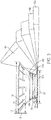
FIG. 3 is an elevation view of the anti-collision aircraft light ofFIG. 2 further illustrating a light radiation pattern. - Referring to the drawings,
FIG. 1 shows anaircraft 100. In the illustrated embodiment, theaircraft 100 includes afore portion 101, anaft portion 102,lateral portions 103 and at least oneanti-collision light 110. In the illustrated embodiment, theaircraft 100 can utilize theanti-collision light 110 to provide alight radiation pattern 112 as required by regulations and operation requirements. In the illustrated embodiment, theanti-collision light 110 can provide alight radiation pattern 112 extending between 0 and 75 degrees in both above and below the horizontal plane. Advantageously, theanti-collision light 110 can provide the requiredlight radiation pattern 112 with a minimum number ofanti-collision lights 110, a minimum part count and maximum efficiency, while reducing complexity and positional tolerances. - Referring to
FIGS. 2 and3 , theanti-collision light source 110 is shown. In the illustrated embodiment, theanti-collision light source 110 includes alight element 122 and areflector 130. In certain embodiments, anti-collision lighting systems are regulated by US Federal Aviation Regulation 14 CFR 25.1441. - Federal Aviation Regulation 14 CFR 25.1401 requires a field of coverage that must extend at least 75 degrees above and 75 degrees below the horizontal plane of the airplane. 14 CFR 25.1401 additionally requires that the field of coverage must be valid within any vertical plane, between 0 to 360 degrees. Further, 14 CFR 25.1401 requires the following intensities at the following angle above and below the horizontal plane:
Angle above or below the horizontal plane Effective intensity (candles) 0° to 5° 400 5° to 10° 240 10° to 20° 80 20° to 30° 40 30° to 75° 20 - In the illustrated embodiment, the
anti-collision light source 110 can provide a desiredlight radiation pattern 150a-150n while minimizing the number of required optical elements or additional light sources. Further, theanti-collision light 110 can increase optical efficiency and light output from a givenlight element 122 while simplifying construction, tolerances, and part count of theanti-collision light 110. - In the illustrated embodiment, the
light element 122 can provide lighting to be directed by thereflector 130. Thelight element 122 can be disposed on aboard 120. In the illustrated embodiment, thelight element 122 and thereflector 130 can be affixed to theboard 120. - In the illustrated embodiment, the
light element 122 can be formed in a circular shape having alight element diameter 123. Thelight element diameter 123 can be any suitable diameter.Light element 122 can include light emitting diodes, ring lights, strobes, or any other suitable light element. In certain embodiments, thelight element 122 can include multipleindividual lighting elements 122a to provide lighting. Advantageously,anti-collision light source 110 can utilize a lesspowerful light element 122 or a fewer number ofindividual lighting elements 122a while still providing the desired intensity output of theanti-collision light source 110. - In the illustrated embodiment, the
reflector 130 reflects light fromlight element 122 to form a desiredlight radiation pattern 150a-150n. In the illustrated embodiment, thereflector 130 has afirst end 132, asecond end 134, a plurality offacets 140a-140n, and a plurality ofslits 136. In the illustrated embodiment, the geometry and construction of thereflector 130 allows for light radiation to be guided into high intensity regions and patterns are required by regulations and operational requirements. - In the illustrated embodiment, the
reflector 130 is disposed on theboard 120 within thelight element 122. Thereflector 130 can have a generally fustro-conical shape that is concentric with thelight element 122. In certain embodiments, thereflector 130 is a parabolic reflector. In the illustrated embodiment, thefirst end 132 is generally coplanar to thelight element 122. In certain embodiments, thefirst end 132 is disposed in a plane above or below thelight element 122. In certain embodiments, thefirst end 132 is coupled to theboard 120. Thefirst end 132 has afirst diameter 133. In the illustrated embodiment, thefirst diameter 133 is smaller than thelight element diameter 123 and is disposed within thelight element 122. The opposite end of thereflector 130 is thesecond end 134. In the illustrated embodiment, thesecond end 134 is disposed away from thelight element 122. Thesecond end 134 has asecond end diameter 135 that may be greater than thelight element diameter 123. In the illustrated embodiment, thereflector 130 hassecond end diameter 135 that is larger than thefirst end diameter 133. - In the illustrated embodiment, the
reflector 130 can include a plurality offacets 140a-140n disposed between thefirst end 132 and thesecond end 134. In the illustrated embodiment, eachfacet 140n is a fustro-conical section that has a facetfirst diameter 141n and a facetsecond diameter 143n. In the illustrated embodiment,various facets 140a-140n can reflect and direct various portions of the light output fromlight element 123 to desiredradiation patterns 150a-150n. - In the illustrated embodiment, the
radiation pattern 150a-150n is illustrated. In certain embodiments, theradiation pattern 150a-150n is designed to comply with certain regulations such as Federal Aviation Regulation 14 CFR 25.1401 to provide prescribed light intensities at various angles above and below the horizontal plane within any vertical plane. Advantageously, the features of thereflector 130 allow for theradiation pattern 150a-150n to comply with the regulations while avoiding additional or higherenergy light elements 122. - In the illustrated embodiment, the orientation, position, size and the facet ratio of the
facets 140a-140n can determine the location and intensity of theradiation patterns 150a-150n. The facet ratio can be described as the ratio between the facetfirst diameter 141n and the facetsecond diameter 143n. In the illustrated embodiment, the facet ratio describes the relationship between the facetfirst diameter 141n and the facetsecond diameter 143n. The facet ratio can describe the slope of eachfacet 140n of thereflector 130. In the illustrated embodiment, eachfacet 140n has an associated facet ratio to directradiation patterns 150a-150n as desired. Advantageously,facets 140a-140n allow for light to be easily directed inradiation patterns 150a-150n without requiring precise focusing of thereflector 130. - In the illustrated embodiment, the
reflector 130 can include a plurality ofslits 136.Slits 136 can be disposed at thesecond end 134 of thereflector 130. In the illustrated embodiment, theslits 136 can each have aslit length 137 that extends inward radially toward the center of thereflector 130. In the illustrated embodiment, theslits 136 can allow for emitted light energy to selectively pass through theslits 136 instead of being reflected by thereflector 130 to allow for the desired or required light intensity at greater angles such as 75 degrees above or below the horizontal plane. In the illustrated embodiment, in the area of thesecond end 134 between theslits 136, light energy is directed to other portions of theradiation pattern 150a-150n. In the illustrated embodiment, theslits 136 are sized and spaced apart to prevent shadows or other undesirable radiation patterns. Geometric characteristics of theslits 136 can be altered to achieve the desiredradiation pattern 150a-150n. Geometric characteristics of theslits 136 include, but are not limited to slit number, slit angle, slit depth, slit size, and slit profile. Further, in certain embodiments, by introducingslits 136, thereflector height 130 can be increased to allow for more efficient operation of the anti-collisionlight source 110. In certain embodiments, withslits 136, thesecond end 134 can have a greatersecond end diameter 135 to further allow for more efficient operation of the anti-collisionlight source 110. - The terminology used herein is for the purpose of describing particular embodiments only and is not intended to be limiting of the embodiments. While the description of the present embodiments has been presented for purposes of illustration and description, it is not intended to be exhaustive or limited to the embodiments in the form disclosed. Many modifications, variations, alterations, substitutions or equivalent arrangement not hereto described will be apparent to those of ordinary skill in the art without departing from the scope and spirit of the embodiments. Additionally, while various embodiments have been described, it is to be understood that aspects may include only some of the described embodiments. Accordingly, the embodiments are not to be seen as limited by the foregoing description, but are only limited by the scope of the appended claims.
Claims (15)
- A light source, comprising:a circular light element (122) having a light source diameter (123); anda reflector (130) disposed at least partially within the circular light element (122), the reflector (130) having a first end (132) with a first diameter (133) and a second end (134) with a second diameter (135), wherein the first diameter (133) is less than the light source diameter (123) and the second diameter (135) is larger than the light source diameter (123), the second end (134) having a plurality of slits (136).
- The light source of claim 1, wherein each of the plurality of slits (136) extends radially inward from the second diameter (135).
- The light source of claim 1 or 2, wherein the reflector (130) is disposed concentrically within the circular light source.
- The light source of any preceding claim, wherein the reflector (130) is parabolic.
- The light source of any of claims 1 to 3, wherein the reflector (130) has a plurality of facets (140a-140n).
- The light source of claim 5, wherein each of the plurality of facets (140a-140n) has a facet ratio between each of a first facet diameter (141n) and a second facet diameter (143n).
- The light source of any preceding claim, wherein the light source provides a radiation pattern of at least 0 to 75 degrees above and below a horizontal plane.
- The light source of any preceding claim, wherein the circular light element includes a plurality of light emitting diodes.
- The light source of any preceding claim, wherein the circular light element is a single light element.
- The light source of any preceding claim, wherein the first end is coplanar to the circular light element.
- A light source, comprising:a circular light element (122) having a light source diameter (123); anda reflector (130) disposed at least partially within the circular light element (122)wherein the reflector (130) has a plurality of facets (140a-140n), wherein each of the plurality of facets (140a-140n) has a facet ratio between each of a first facet diameter (141 n) and a second facet diameter (143n).
- The light source of claim 11, the reflector (130) further comprising a first end (132) with a first diameter (133) and a second end (134) with a second diameter (135), wherein the first diameter (133) is less than the light source diameter (123) and the second diameter (135) is larger than the light source diameter (123), the second end (134) having a plurality of slits (136).
- The light source of claim 12, wherein each of the plurality of slits (136) extends radially inward from the second diameter (135).
- The light source of claim 11, 12 or 13, wherein the reflector (130) is disposed concentrically within the circular light source.
- The light source of any of claims 11 to 14, wherein the light source provides a radiation pattern of at least 0 to 75 degrees above and below a horizontal plane.
Applications Claiming Priority (1)
| Application Number | Priority Date | Filing Date | Title |
|---|---|---|---|
| US15/073,094 US10150575B2 (en) | 2016-03-17 | 2016-03-17 | Aircraft anti-collision light |
Publications (2)
| Publication Number | Publication Date |
|---|---|
| EP3219623A1 true EP3219623A1 (en) | 2017-09-20 |
| EP3219623B1 EP3219623B1 (en) | 2019-06-12 |
Family
ID=57821875
Family Applications (1)
| Application Number | Title | Priority Date | Filing Date |
|---|---|---|---|
| EP17151677.6A Active EP3219623B1 (en) | 2016-03-17 | 2017-01-16 | Aircraft anti-collision light |
Country Status (5)
| Country | Link |
|---|---|
| US (1) | US10150575B2 (en) |
| EP (1) | EP3219623B1 (en) |
| CN (1) | CN107202302B (en) |
| BR (1) | BR102017000811B1 (en) |
| CA (1) | CA2954880C (en) |
Cited By (2)
| Publication number | Priority date | Publication date | Assignee | Title |
|---|---|---|---|---|
| EP3476745A1 (en) * | 2017-10-24 | 2019-05-01 | Goodrich Lighting Systems GmbH | Aircraft beacon light and aircraft comprising the same |
| EP3741684A1 (en) * | 2019-05-23 | 2020-11-25 | Be Aerospace, Inc. | Vehicle anti-collision light with discontinous reflector |
Families Citing this family (3)
| Publication number | Priority date | Publication date | Assignee | Title |
|---|---|---|---|---|
| CN109519867A (en) * | 2018-11-15 | 2019-03-26 | 中国直升机设计研究所 | A kind of double light anticollision beacons |
| US11046455B2 (en) | 2019-10-23 | 2021-06-29 | B/E Aerospace, Inc. | Anti-collision light assembly |
| EP4063278B1 (en) | 2021-03-25 | 2024-08-28 | Goodrich Lighting Systems GmbH & Co. KG | Aircraft anti-collision light, aircraft comprising an aircraft anti-collision light, and method of operating an aircraft anti-collision light |
Citations (4)
| Publication number | Priority date | Publication date | Assignee | Title |
|---|---|---|---|---|
| WO2006091225A1 (en) * | 2005-01-13 | 2006-08-31 | Honeywell International, Inc. | Body mounted led-based anti-collision light for aircraft |
| US20070002572A1 (en) * | 2005-06-06 | 2007-01-04 | Pascal Ewig | Anti-collision luminous signaling device |
| WO2009084049A1 (en) * | 2007-12-28 | 2009-07-09 | Sirio Panel S.P.A. | Anti -collision light for aircraft |
| US20100027281A1 (en) * | 2008-07-31 | 2010-02-04 | Waters Stanley E | LED Anti-Collision Light for Commercial Aircraft |
Family Cites Families (9)
| Publication number | Priority date | Publication date | Assignee | Title |
|---|---|---|---|---|
| US8360615B2 (en) * | 2000-05-08 | 2013-01-29 | Farlight, Llc | LED light module for omnidirectional luminaire |
| US8033683B2 (en) | 2008-02-15 | 2011-10-11 | PerkinElmer LED Solutions, Inc. | Staggered LED based high-intensity light |
| WO2012095905A1 (en) * | 2011-01-14 | 2012-07-19 | パナソニック株式会社 | Illumination light source |
| TWI410581B (en) | 2011-06-30 | 2013-10-01 | Lextar Electronics Corp | Lamp structure |
| KR101227525B1 (en) * | 2011-08-12 | 2013-01-31 | 엘지전자 주식회사 | Lighting apparatus |
| US8672512B2 (en) * | 2011-09-23 | 2014-03-18 | Hong Kong Applied Science and Technology Research Institute Company Limited | Omni reflective optics for wide angle emission LED light bulb |
| CN103851378A (en) * | 2012-12-06 | 2014-06-11 | 展晶科技(深圳)有限公司 | Light emitting diode lamp |
| CN104344246A (en) * | 2013-08-05 | 2015-02-11 | 展晶科技(深圳)有限公司 | Light emitting diode lamp |
| CN104344247A (en) * | 2013-08-05 | 2015-02-11 | 展晶科技(深圳)有限公司 | Light emitting diode lamp |
-
2016
- 2016-03-17 US US15/073,094 patent/US10150575B2/en active Active
-
2017
- 2017-01-13 CA CA2954880A patent/CA2954880C/en active Active
- 2017-01-13 BR BR102017000811-8A patent/BR102017000811B1/en active IP Right Grant
- 2017-01-16 EP EP17151677.6A patent/EP3219623B1/en active Active
- 2017-01-17 CN CN201710032940.2A patent/CN107202302B/en active Active
Patent Citations (4)
| Publication number | Priority date | Publication date | Assignee | Title |
|---|---|---|---|---|
| WO2006091225A1 (en) * | 2005-01-13 | 2006-08-31 | Honeywell International, Inc. | Body mounted led-based anti-collision light for aircraft |
| US20070002572A1 (en) * | 2005-06-06 | 2007-01-04 | Pascal Ewig | Anti-collision luminous signaling device |
| WO2009084049A1 (en) * | 2007-12-28 | 2009-07-09 | Sirio Panel S.P.A. | Anti -collision light for aircraft |
| US20100027281A1 (en) * | 2008-07-31 | 2010-02-04 | Waters Stanley E | LED Anti-Collision Light for Commercial Aircraft |
Cited By (3)
| Publication number | Priority date | Publication date | Assignee | Title |
|---|---|---|---|---|
| EP3476745A1 (en) * | 2017-10-24 | 2019-05-01 | Goodrich Lighting Systems GmbH | Aircraft beacon light and aircraft comprising the same |
| US11072437B2 (en) | 2017-10-24 | 2021-07-27 | Goodrich Lighting Systems Gmbh | Aircraft beacon light and aircraft comprising the same |
| EP3741684A1 (en) * | 2019-05-23 | 2020-11-25 | Be Aerospace, Inc. | Vehicle anti-collision light with discontinous reflector |
Also Published As
| Publication number | Publication date |
|---|---|
| CN107202302A (en) | 2017-09-26 |
| EP3219623B1 (en) | 2019-06-12 |
| CA2954880A1 (en) | 2017-09-17 |
| US20170267375A1 (en) | 2017-09-21 |
| BR102017000811A2 (en) | 2017-09-19 |
| BR102017000811B1 (en) | 2023-04-18 |
| CA2954880C (en) | 2023-10-31 |
| CN107202302B (en) | 2021-03-16 |
| US10150575B2 (en) | 2018-12-11 |
Similar Documents
| Publication | Publication Date | Title |
|---|---|---|
| EP3219623B1 (en) | Aircraft anti-collision light | |
| EP2995501B1 (en) | Dynamic aircraft headlight and method of operating a dynamic aircraft headlight | |
| US8454212B2 (en) | Anti-collision light for aircraft | |
| CN108087834B (en) | Multi-beam lamp | |
| EP2985229B1 (en) | Exterior aircraft light unit and aircraft comprising the same | |
| EP3168160B1 (en) | Exterior aircraft light unit and aircraft comprising the same | |
| US10246199B2 (en) | Lighting device for aircraft allowing the integration of additional functions at its center | |
| EP2837566B1 (en) | Exterior aircraft light unit and aircraft comprising the exterior aircraft light unit | |
| EP2985228B1 (en) | Exterior aircraft light unit and aircraft comprising the same | |
| US10899470B2 (en) | Multifunctional aircraft landing light with static function switching | |
| US11072437B2 (en) | Aircraft beacon light and aircraft comprising the same | |
| US20180334264A1 (en) | Combined aircraft take-off and tower signal light unit and aircraft comprising the same | |
| US10435174B2 (en) | Optical device for lighting and/or signaling light for aircraft and light comprising such an optical device | |
| EP4063278B1 (en) | Aircraft anti-collision light, aircraft comprising an aircraft anti-collision light, and method of operating an aircraft anti-collision light | |
| EP3284681B1 (en) | Aircraft head light | |
| CN111981436B (en) | Multi-faceted discontinuous reflector | |
| EP3213997B1 (en) | Dual mode aft light |
Legal Events
| Date | Code | Title | Description |
|---|---|---|---|
| PUAI | Public reference made under article 153(3) epc to a published international application that has entered the european phase |
Free format text: ORIGINAL CODE: 0009012 |
|
| STAA | Information on the status of an ep patent application or granted ep patent |
Free format text: STATUS: THE APPLICATION HAS BEEN PUBLISHED |
|
| AK | Designated contracting states |
Kind code of ref document: A1 Designated state(s): AL AT BE BG CH CY CZ DE DK EE ES FI FR GB GR HR HU IE IS IT LI LT LU LV MC MK MT NL NO PL PT RO RS SE SI SK SM TR |
|
| AX | Request for extension of the european patent |
Extension state: BA ME |
|
| STAA | Information on the status of an ep patent application or granted ep patent |
Free format text: STATUS: REQUEST FOR EXAMINATION WAS MADE |
|
| 17P | Request for examination filed |
Effective date: 20180320 |
|
| RBV | Designated contracting states (corrected) |
Designated state(s): AL AT BE BG CH CY CZ DE DK EE ES FI FR GB GR HR HU IE IS IT LI LT LU LV MC MK MT NL NO PL PT RO RS SE SI SK SM TR |
|
| GRAP | Despatch of communication of intention to grant a patent |
Free format text: ORIGINAL CODE: EPIDOSNIGR1 |
|
| STAA | Information on the status of an ep patent application or granted ep patent |
Free format text: STATUS: GRANT OF PATENT IS INTENDED |
|
| INTG | Intention to grant announced |
Effective date: 20190103 |
|
| GRAS | Grant fee paid |
Free format text: ORIGINAL CODE: EPIDOSNIGR3 |
|
| GRAA | (expected) grant |
Free format text: ORIGINAL CODE: 0009210 |
|
| STAA | Information on the status of an ep patent application or granted ep patent |
Free format text: STATUS: THE PATENT HAS BEEN GRANTED |
|
| AK | Designated contracting states |
Kind code of ref document: B1 Designated state(s): AL AT BE BG CH CY CZ DE DK EE ES FI FR GB GR HR HU IE IS IT LI LT LU LV MC MK MT NL NO PL PT RO RS SE SI SK SM TR |
|
| REG | Reference to a national code |
Ref country code: GB Ref legal event code: FG4D |
|
| REG | Reference to a national code |
Ref country code: CH Ref legal event code: EP |
|
| REG | Reference to a national code |
Ref country code: AT Ref legal event code: REF Ref document number: 1142246 Country of ref document: AT Kind code of ref document: T Effective date: 20190615 |
|
| REG | Reference to a national code |
Ref country code: DE Ref legal event code: R096 Ref document number: 602017004358 Country of ref document: DE |
|
| REG | Reference to a national code |
Ref country code: IE Ref legal event code: FG4D |
|
| REG | Reference to a national code |
Ref country code: NL Ref legal event code: MP Effective date: 20190612 |
|
| REG | Reference to a national code |
Ref country code: LT Ref legal event code: MG4D |
|
| PG25 | Lapsed in a contracting state [announced via postgrant information from national office to epo] |
Ref country code: AL Free format text: LAPSE BECAUSE OF FAILURE TO SUBMIT A TRANSLATION OF THE DESCRIPTION OR TO PAY THE FEE WITHIN THE PRESCRIBED TIME-LIMIT Effective date: 20190612 Ref country code: SE Free format text: LAPSE BECAUSE OF FAILURE TO SUBMIT A TRANSLATION OF THE DESCRIPTION OR TO PAY THE FEE WITHIN THE PRESCRIBED TIME-LIMIT Effective date: 20190612 Ref country code: LT Free format text: LAPSE BECAUSE OF FAILURE TO SUBMIT A TRANSLATION OF THE DESCRIPTION OR TO PAY THE FEE WITHIN THE PRESCRIBED TIME-LIMIT Effective date: 20190612 Ref country code: HR Free format text: LAPSE BECAUSE OF FAILURE TO SUBMIT A TRANSLATION OF THE DESCRIPTION OR TO PAY THE FEE WITHIN THE PRESCRIBED TIME-LIMIT Effective date: 20190612 Ref country code: FI Free format text: LAPSE BECAUSE OF FAILURE TO SUBMIT A TRANSLATION OF THE DESCRIPTION OR TO PAY THE FEE WITHIN THE PRESCRIBED TIME-LIMIT Effective date: 20190612 Ref country code: NO Free format text: LAPSE BECAUSE OF FAILURE TO SUBMIT A TRANSLATION OF THE DESCRIPTION OR TO PAY THE FEE WITHIN THE PRESCRIBED TIME-LIMIT Effective date: 20190912 |
|
| PG25 | Lapsed in a contracting state [announced via postgrant information from national office to epo] |
Ref country code: GR Free format text: LAPSE BECAUSE OF FAILURE TO SUBMIT A TRANSLATION OF THE DESCRIPTION OR TO PAY THE FEE WITHIN THE PRESCRIBED TIME-LIMIT Effective date: 20190913 Ref country code: RS Free format text: LAPSE BECAUSE OF FAILURE TO SUBMIT A TRANSLATION OF THE DESCRIPTION OR TO PAY THE FEE WITHIN THE PRESCRIBED TIME-LIMIT Effective date: 20190612 Ref country code: BG Free format text: LAPSE BECAUSE OF FAILURE TO SUBMIT A TRANSLATION OF THE DESCRIPTION OR TO PAY THE FEE WITHIN THE PRESCRIBED TIME-LIMIT Effective date: 20190912 Ref country code: LV Free format text: LAPSE BECAUSE OF FAILURE TO SUBMIT A TRANSLATION OF THE DESCRIPTION OR TO PAY THE FEE WITHIN THE PRESCRIBED TIME-LIMIT Effective date: 20190612 |
|
| REG | Reference to a national code |
Ref country code: AT Ref legal event code: MK05 Ref document number: 1142246 Country of ref document: AT Kind code of ref document: T Effective date: 20190612 |
|
| PG25 | Lapsed in a contracting state [announced via postgrant information from national office to epo] |
Ref country code: NL Free format text: LAPSE BECAUSE OF FAILURE TO SUBMIT A TRANSLATION OF THE DESCRIPTION OR TO PAY THE FEE WITHIN THE PRESCRIBED TIME-LIMIT Effective date: 20190612 Ref country code: AT Free format text: LAPSE BECAUSE OF FAILURE TO SUBMIT A TRANSLATION OF THE DESCRIPTION OR TO PAY THE FEE WITHIN THE PRESCRIBED TIME-LIMIT Effective date: 20190612 Ref country code: PT Free format text: LAPSE BECAUSE OF FAILURE TO SUBMIT A TRANSLATION OF THE DESCRIPTION OR TO PAY THE FEE WITHIN THE PRESCRIBED TIME-LIMIT Effective date: 20191014 Ref country code: SK Free format text: LAPSE BECAUSE OF FAILURE TO SUBMIT A TRANSLATION OF THE DESCRIPTION OR TO PAY THE FEE WITHIN THE PRESCRIBED TIME-LIMIT Effective date: 20190612 Ref country code: CZ Free format text: LAPSE BECAUSE OF FAILURE TO SUBMIT A TRANSLATION OF THE DESCRIPTION OR TO PAY THE FEE WITHIN THE PRESCRIBED TIME-LIMIT Effective date: 20190612 Ref country code: RO Free format text: LAPSE BECAUSE OF FAILURE TO SUBMIT A TRANSLATION OF THE DESCRIPTION OR TO PAY THE FEE WITHIN THE PRESCRIBED TIME-LIMIT Effective date: 20190612 Ref country code: EE Free format text: LAPSE BECAUSE OF FAILURE TO SUBMIT A TRANSLATION OF THE DESCRIPTION OR TO PAY THE FEE WITHIN THE PRESCRIBED TIME-LIMIT Effective date: 20190612 |
|
| PG25 | Lapsed in a contracting state [announced via postgrant information from national office to epo] |
Ref country code: ES Free format text: LAPSE BECAUSE OF FAILURE TO SUBMIT A TRANSLATION OF THE DESCRIPTION OR TO PAY THE FEE WITHIN THE PRESCRIBED TIME-LIMIT Effective date: 20190612 Ref country code: IT Free format text: LAPSE BECAUSE OF FAILURE TO SUBMIT A TRANSLATION OF THE DESCRIPTION OR TO PAY THE FEE WITHIN THE PRESCRIBED TIME-LIMIT Effective date: 20190612 Ref country code: SM Free format text: LAPSE BECAUSE OF FAILURE TO SUBMIT A TRANSLATION OF THE DESCRIPTION OR TO PAY THE FEE WITHIN THE PRESCRIBED TIME-LIMIT Effective date: 20190612 Ref country code: IS Free format text: LAPSE BECAUSE OF FAILURE TO SUBMIT A TRANSLATION OF THE DESCRIPTION OR TO PAY THE FEE WITHIN THE PRESCRIBED TIME-LIMIT Effective date: 20191012 |
|
| REG | Reference to a national code |
Ref country code: DE Ref legal event code: R097 Ref document number: 602017004358 Country of ref document: DE |
|
| PG25 | Lapsed in a contracting state [announced via postgrant information from national office to epo] |
Ref country code: TR Free format text: LAPSE BECAUSE OF FAILURE TO SUBMIT A TRANSLATION OF THE DESCRIPTION OR TO PAY THE FEE WITHIN THE PRESCRIBED TIME-LIMIT Effective date: 20190612 |
|
| PLBE | No opposition filed within time limit |
Free format text: ORIGINAL CODE: 0009261 |
|
| STAA | Information on the status of an ep patent application or granted ep patent |
Free format text: STATUS: NO OPPOSITION FILED WITHIN TIME LIMIT |
|
| PG25 | Lapsed in a contracting state [announced via postgrant information from national office to epo] |
Ref country code: PL Free format text: LAPSE BECAUSE OF FAILURE TO SUBMIT A TRANSLATION OF THE DESCRIPTION OR TO PAY THE FEE WITHIN THE PRESCRIBED TIME-LIMIT Effective date: 20190612 Ref country code: DK Free format text: LAPSE BECAUSE OF FAILURE TO SUBMIT A TRANSLATION OF THE DESCRIPTION OR TO PAY THE FEE WITHIN THE PRESCRIBED TIME-LIMIT Effective date: 20190612 |
|
| 26N | No opposition filed |
Effective date: 20200313 |
|
| PG25 | Lapsed in a contracting state [announced via postgrant information from national office to epo] |
Ref country code: IS Free format text: LAPSE BECAUSE OF FAILURE TO SUBMIT A TRANSLATION OF THE DESCRIPTION OR TO PAY THE FEE WITHIN THE PRESCRIBED TIME-LIMIT Effective date: 20200224 Ref country code: SI Free format text: LAPSE BECAUSE OF FAILURE TO SUBMIT A TRANSLATION OF THE DESCRIPTION OR TO PAY THE FEE WITHIN THE PRESCRIBED TIME-LIMIT Effective date: 20190612 |
|
| PG2D | Information on lapse in contracting state deleted |
Ref country code: IS |
|
| REG | Reference to a national code |
Ref country code: DE Ref legal event code: R119 Ref document number: 602017004358 Country of ref document: DE |
|
| PG25 | Lapsed in a contracting state [announced via postgrant information from national office to epo] |
Ref country code: MC Free format text: LAPSE BECAUSE OF FAILURE TO SUBMIT A TRANSLATION OF THE DESCRIPTION OR TO PAY THE FEE WITHIN THE PRESCRIBED TIME-LIMIT Effective date: 20190612 |
|
| REG | Reference to a national code |
Ref country code: CH Ref legal event code: PL |
|
| REG | Reference to a national code |
Ref country code: BE Ref legal event code: MM Effective date: 20200131 |
|
| PG25 | Lapsed in a contracting state [announced via postgrant information from national office to epo] |
Ref country code: LU Free format text: LAPSE BECAUSE OF NON-PAYMENT OF DUE FEES Effective date: 20200116 Ref country code: DE Free format text: LAPSE BECAUSE OF NON-PAYMENT OF DUE FEES Effective date: 20200801 |
|
| PG25 | Lapsed in a contracting state [announced via postgrant information from national office to epo] |
Ref country code: CH Free format text: LAPSE BECAUSE OF NON-PAYMENT OF DUE FEES Effective date: 20200131 Ref country code: LI Free format text: LAPSE BECAUSE OF NON-PAYMENT OF DUE FEES Effective date: 20200131 Ref country code: BE Free format text: LAPSE BECAUSE OF NON-PAYMENT OF DUE FEES Effective date: 20200131 |
|
| PG25 | Lapsed in a contracting state [announced via postgrant information from national office to epo] |
Ref country code: IE Free format text: LAPSE BECAUSE OF NON-PAYMENT OF DUE FEES Effective date: 20200116 |
|
| PG25 | Lapsed in a contracting state [announced via postgrant information from national office to epo] |
Ref country code: MT Free format text: LAPSE BECAUSE OF FAILURE TO SUBMIT A TRANSLATION OF THE DESCRIPTION OR TO PAY THE FEE WITHIN THE PRESCRIBED TIME-LIMIT Effective date: 20190612 Ref country code: CY Free format text: LAPSE BECAUSE OF FAILURE TO SUBMIT A TRANSLATION OF THE DESCRIPTION OR TO PAY THE FEE WITHIN THE PRESCRIBED TIME-LIMIT Effective date: 20190612 |
|
| PG25 | Lapsed in a contracting state [announced via postgrant information from national office to epo] |
Ref country code: MK Free format text: LAPSE BECAUSE OF FAILURE TO SUBMIT A TRANSLATION OF THE DESCRIPTION OR TO PAY THE FEE WITHIN THE PRESCRIBED TIME-LIMIT Effective date: 20190612 |
|
| PGFP | Annual fee paid to national office [announced via postgrant information from national office to epo] |
Ref country code: GB Payment date: 20251220 Year of fee payment: 10 |
|
| PGFP | Annual fee paid to national office [announced via postgrant information from national office to epo] |
Ref country code: FR Payment date: 20251217 Year of fee payment: 10 |
|
| P01 | Opt-out of the competence of the unified patent court (upc) registered |
Free format text: CASE NUMBER: UPC_APP_0017227_3219623/2025 Effective date: 20251211 |