EP3219613A1 - Pressurized potable water system with conformal shape water storage tank - Google Patents
Pressurized potable water system with conformal shape water storage tank Download PDFInfo
- Publication number
- EP3219613A1 EP3219613A1 EP17161260.9A EP17161260A EP3219613A1 EP 3219613 A1 EP3219613 A1 EP 3219613A1 EP 17161260 A EP17161260 A EP 17161260A EP 3219613 A1 EP3219613 A1 EP 3219613A1
- Authority
- EP
- European Patent Office
- Prior art keywords
- pressure
- tank
- water
- pressure tank
- storage tank
- Prior art date
- Legal status (The legal status is an assumption and is not a legal conclusion. Google has not performed a legal analysis and makes no representation as to the accuracy of the status listed.)
- Granted
Links
Images

Classifications
-
- B—PERFORMING OPERATIONS; TRANSPORTING
- B60—VEHICLES IN GENERAL
- B60R—VEHICLES, VEHICLE FITTINGS, OR VEHICLE PARTS, NOT OTHERWISE PROVIDED FOR
- B60R15/00—Arrangements or adaptations of sanitation devices
- B60R15/02—Washing facilities
-
- B—PERFORMING OPERATIONS; TRANSPORTING
- B64—AIRCRAFT; AVIATION; COSMONAUTICS
- B64D—EQUIPMENT FOR FITTING IN OR TO AIRCRAFT; FLIGHT SUITS; PARACHUTES; ARRANGEMENT OR MOUNTING OF POWER PLANTS OR PROPULSION TRANSMISSIONS IN AIRCRAFT
- B64D11/00—Passenger or crew accommodation; Flight-deck installations not otherwise provided for
- B64D11/02—Toilet fittings
-
- E—FIXED CONSTRUCTIONS
- E03—WATER SUPPLY; SEWERAGE
- E03B—INSTALLATIONS OR METHODS FOR OBTAINING, COLLECTING, OR DISTRIBUTING WATER
- E03B11/00—Arrangements or adaptations of tanks for water supply
- E03B11/02—Arrangements or adaptations of tanks for water supply for domestic or like local water supply
- E03B11/06—Arrangements or adaptations of tanks for water supply for domestic or like local water supply with air regulators
- E03B11/08—Air regulators
-
- B—PERFORMING OPERATIONS; TRANSPORTING
- B60—VEHICLES IN GENERAL
- B60R—VEHICLES, VEHICLE FITTINGS, OR VEHICLE PARTS, NOT OTHERWISE PROVIDED FOR
- B60R15/00—Arrangements or adaptations of sanitation devices
- B60R15/04—Toilet facilities
-
- B—PERFORMING OPERATIONS; TRANSPORTING
- B61—RAILWAYS
- B61D—BODY DETAILS OR KINDS OF RAILWAY VEHICLES
- B61D35/00—Sanitation
-
- B—PERFORMING OPERATIONS; TRANSPORTING
- B64—AIRCRAFT; AVIATION; COSMONAUTICS
- B64D—EQUIPMENT FOR FITTING IN OR TO AIRCRAFT; FLIGHT SUITS; PARACHUTES; ARRANGEMENT OR MOUNTING OF POWER PLANTS OR PROPULSION TRANSMISSIONS IN AIRCRAFT
- B64D11/00—Passenger or crew accommodation; Flight-deck installations not otherwise provided for
-
- B—PERFORMING OPERATIONS; TRANSPORTING
- B64—AIRCRAFT; AVIATION; COSMONAUTICS
- B64D—EQUIPMENT FOR FITTING IN OR TO AIRCRAFT; FLIGHT SUITS; PARACHUTES; ARRANGEMENT OR MOUNTING OF POWER PLANTS OR PROPULSION TRANSMISSIONS IN AIRCRAFT
- B64D11/00—Passenger or crew accommodation; Flight-deck installations not otherwise provided for
- B64D11/04—Galleys
-
- B—PERFORMING OPERATIONS; TRANSPORTING
- B67—OPENING, CLOSING OR CLEANING BOTTLES, JARS OR SIMILAR CONTAINERS; LIQUID HANDLING
- B67D—DISPENSING, DELIVERING OR TRANSFERRING LIQUIDS, NOT OTHERWISE PROVIDED FOR
- B67D7/00—Apparatus or devices for transferring liquids from bulk storage containers or reservoirs into vehicles or into portable containers, e.g. for retail sale purposes
- B67D7/02—Apparatus or devices for transferring liquids from bulk storage containers or reservoirs into vehicles or into portable containers, e.g. for retail sale purposes for transferring liquids other than fuel or lubricants
- B67D7/0238—Apparatus or devices for transferring liquids from bulk storage containers or reservoirs into vehicles or into portable containers, e.g. for retail sale purposes for transferring liquids other than fuel or lubricants utilising compressed air or other gas acting directly or indirectly on liquids in storage containers
- B67D7/0266—Apparatus or devices for transferring liquids from bulk storage containers or reservoirs into vehicles or into portable containers, e.g. for retail sale purposes for transferring liquids other than fuel or lubricants utilising compressed air or other gas acting directly or indirectly on liquids in storage containers by gas acting directly on the liquid
-
- B—PERFORMING OPERATIONS; TRANSPORTING
- B67—OPENING, CLOSING OR CLEANING BOTTLES, JARS OR SIMILAR CONTAINERS; LIQUID HANDLING
- B67D—DISPENSING, DELIVERING OR TRANSFERRING LIQUIDS, NOT OTHERWISE PROVIDED FOR
- B67D7/00—Apparatus or devices for transferring liquids from bulk storage containers or reservoirs into vehicles or into portable containers, e.g. for retail sale purposes
- B67D7/06—Details or accessories
- B67D7/36—Arrangements of flow- or pressure-control valves
-
- B—PERFORMING OPERATIONS; TRANSPORTING
- B67—OPENING, CLOSING OR CLEANING BOTTLES, JARS OR SIMILAR CONTAINERS; LIQUID HANDLING
- B67D—DISPENSING, DELIVERING OR TRANSFERRING LIQUIDS, NOT OTHERWISE PROVIDED FOR
- B67D7/00—Apparatus or devices for transferring liquids from bulk storage containers or reservoirs into vehicles or into portable containers, e.g. for retail sale purposes
- B67D7/06—Details or accessories
- B67D7/58—Arrangements of pumps
- B67D7/62—Arrangements of pumps power operated
-
- B—PERFORMING OPERATIONS; TRANSPORTING
- B67—OPENING, CLOSING OR CLEANING BOTTLES, JARS OR SIMILAR CONTAINERS; LIQUID HANDLING
- B67D—DISPENSING, DELIVERING OR TRANSFERRING LIQUIDS, NOT OTHERWISE PROVIDED FOR
- B67D7/00—Apparatus or devices for transferring liquids from bulk storage containers or reservoirs into vehicles or into portable containers, e.g. for retail sale purposes
- B67D7/06—Details or accessories
- B67D7/72—Devices for applying air or other gas pressure for forcing liquid to delivery point
-
- E—FIXED CONSTRUCTIONS
- E03—WATER SUPPLY; SEWERAGE
- E03B—INSTALLATIONS OR METHODS FOR OBTAINING, COLLECTING, OR DISTRIBUTING WATER
- E03B11/00—Arrangements or adaptations of tanks for water supply
- E03B11/02—Arrangements or adaptations of tanks for water supply for domestic or like local water supply
-
- E—FIXED CONSTRUCTIONS
- E03—WATER SUPPLY; SEWERAGE
- E03B—INSTALLATIONS OR METHODS FOR OBTAINING, COLLECTING, OR DISTRIBUTING WATER
- E03B11/00—Arrangements or adaptations of tanks for water supply
- E03B2011/005—Tanks with two or more separate compartments divided by, e.g. a flexible membrane
-
- Y—GENERAL TAGGING OF NEW TECHNOLOGICAL DEVELOPMENTS; GENERAL TAGGING OF CROSS-SECTIONAL TECHNOLOGIES SPANNING OVER SEVERAL SECTIONS OF THE IPC; TECHNICAL SUBJECTS COVERED BY FORMER USPC CROSS-REFERENCE ART COLLECTIONS [XRACs] AND DIGESTS
- Y02—TECHNOLOGIES OR APPLICATIONS FOR MITIGATION OR ADAPTATION AGAINST CLIMATE CHANGE
- Y02A—TECHNOLOGIES FOR ADAPTATION TO CLIMATE CHANGE
- Y02A20/00—Water conservation; Efficient water supply; Efficient water use
Definitions
- the subject matter disclosed herein relates to water systems. More specifically, the present disclosure relates to potable water systems utilizing conformal-shaped water storage tanks.
- potable water systems to provide water for use by passengers during operation.
- some potable water systems include a large water storage tank which is pressurized with air. The air typically is bleed air from an auxiliary power unit or is provided by a standalone air compressor for the potable water system.
- Aircraft operators typically desire the tank to maximize water volume storage capability, while also minimizing interior aircraft space utilized by the water storage tank. For this reason, the water storage tank is often made to an irregular or conformal shape, meant to fit in an irregular-shaped space allotted for the water storage tank at the interior of the aircraft.
- the water storage tank When pressurized, however, it is difficult to maintain the conformal shape of the water storage tank as the pressure inside the tank attempts to force the tank into a spherical shape. As such, it is required to form the tank from high-strength pressure resistant materials, and it may also be necessary to include external and/or internal structural reinforcement or baffles to the tank to maintain the tank shape when the tank is pressurized. As a result, the water storage tank adversely affects the cost and weight of the potable water system.
- a water supply system in one embodiment, includes a water storage tank having a storage tank outlet, the water storage tank configured to store a volume of water at a first pressure.
- a pressure tank is in fluid communication with the water storage tank and is periodically fillable with water from the water storage tank.
- An air source is fluidly connected to the pressure tank to pressurize the volume of water in the pressure tank to a second pressure greater than the first pressure.
- a pressure tank output line is fluidly connected to the pressure tank to output water from the pressure tank.
- the first pressure is substantially ambient pressure.
- a level sensor is located at the pressure tank to detect when a water level in the pressure tank is such that the pressure tank is in need of refill.
- the level sensor is operably connected to the water storage tank to initiate refill of the pressure tank from the water storage tank when the level sensor detects the pressure tank is in need of refill.
- the pressure tank is two pressure tanks arranged in parallel and flow through the pressure tank output line is switchable between a first pressure tank of the two pressure tanks and a second pressure tank of the two pressure tanks.
- an air valve is operably connected to the air source and the two pressure tanks to selectably admit pressurizing air to the first pressure tank and/or the second pressure tank.
- a storage output valve is operably connected to the water storage tank and the two pressure tanks to selectably admit water into the first pressure tank and/or the second storage tank from the water storage tank.
- a pump urges water from the water storage tank to the pressure tank.
- the water storage tank is formed from one of a plastic or composite material.
- the water storage tank is non-spherical and non-cylindrical.
- the second pressure is in the range of 20-45 pounds per square inch (138-310 MPa).
- a method of operating a water supply system includes storing a volume of water at a first pressure at a water storage tank, urging a portion of the volume of water from the water storage tank into a first pressure tank, urging a volume of air from an air source into the first pressure tank to pressurize the first pressure tank to a second pressure greater than the first pressure, and releasing a flow of water from the first pressure tank via a pressure tank output line fluidly connected to the first pressure tank.
- a water level at the first pressure tank is detected, and the first pressure tank is refilled from the water storage tank based on the detected water level.
- a portion of the volume of water is urged from the water storage tank into a second pressure tank arranged in parallel with the first pressure tank.
- a volume of air is urged from the air source into the second pressure tank to pressurize the second pressure tank to a second pressure greater than the first pressure.
- a flow of water is selectably released from the first pressure tank and/or the second pressure tank via a pressure tank output line fluidly connected to the first pressure tank and the second pressure tank.
- first pressure tank and/or the second pressure tank are selectably filled from the water storage tank through operation of a storage output valve operably connected to the first pressure tank and the second pressure tank.
- first pressure tank and/or the second pressure tank are selectably pressurized through operation of an air valve operably connected to the air source, first pressure tank and second pressure tank.
- water is urged from the water storage tank via a pump.
- the PWS 10 includes a water storage tank 12, configured to contain a volume of water 14 or other fluid at ambient pressure, or at about 1 atmosphere.
- the water storage tank 12 is not constructed as a pressure vessel.
- the water storage tank 12 may have an interior volume of between 10 and 30 gallons.
- the water storage tank 12 may be of a substantially uniform shape, such as a cylinder, or as shown in FIG. 1 may be irregularly-shaped to fit or conform to an aircraft space 16 in which the water storage tank 12 is located.
- the water storage tank 12 may be formed from relatively low strength materials, such as lightweight metals, plastic, composite or rubber materials. Further, because the water storage tank 12 is not constructed as a pressure vessel, it may be formed without internal baffles or internal or external ribs for strength, thereby simplifying construction of the water storage tank 12 and reducing its cost compared to an equivalently-sized pressure vessel.
- the water storage tank 12 includes a storage tank fill port 18, in some embodiments located at an uppermost tank surface 20.
- the water storage tank 12 further includes a storage tank outlet 22, in some embodiments located at a lowermost tank surface 24.
- the water storage tank 12 may include one or more storage tank level sensors 26, to detect a level of the water volume 14 inside the water storage tank 12.
- the water storage tank 12 is connected to a pressure tank 28 via a storage tank output line 30.
- the pressure tank 28 is a pressure vessel configured to hold a volume of between one quart and one gallon of water at any one time.
- the flow of water through the storage tank output line 30 from the water storage tank 12 to the pressure tank 28 may be controlled by a storage output valve 32 located along the storage tank output line 30. While in the embodiment of FIG. 1 , it is located along the storage tank output line, it is to be appreciated that in other embodiments the storage output valve 32 may be positioned elsewhere, for example, at the water storage tank 12 or at the pressure tank 28.
- Flow of water from the water storage tank 12 and the pressure tank 28 may be achieved through gravity if, for example, the storage tank outlet 22 is at a higher elevation that the pressure tank 28, or may be achieved via a motorized pump 34 which may be located, for example, a submersible pump located inside of the water storage tank 12 or may be located along storage tank output line 30.
- the pressure tank 28 further includes one or more level sensors, for example a full level sensor 36 that indicates when pressure tank 28 is full of water, and a refill level sensor 38 that indicates when the water level in the pressure tank 28 is at a level such that it should be refilled from the water storage tank 12.
- the pressure tank 28 is pressurized to a pressure above ambient, or above 1 atmosphere through the introduction of air pressure from an air source 40.
- the air source may be, for example, bleed air from an aircraft engine or auxiliary power unit compressor (not shown).
- the air flow is urged from the air source 40 along an air line 42 and into the pressure tank 28, under the control of an air valve 44 located along the air line 42.
- Further components such as an air pressure regulator 46 to control the air pressure entering the air line 42, a check valve 48 to protect the air line 42 from reversing flow, and an air filter 50 to remove contaminants from the air, may also be located along the air line 42.
- a vent 52 is connected to the air valve 44 to allow for venting air from the pressure tank 28 to reduce the pressure in the pressure tank 28.
- the pressure tank 28 is connected to a pressure tank output line 54 through a water valve 56 to provide a pressurized water supply upon request.
- the water storage tank 12 is filled with the water volume 14, controller 58 reads the level sensors 36, 38 at the pressure tank 28 and determines that pressure tank 28 needs to be refilled.
- Storage output valve 32 is opened and the pressure tank 28 is filled until level sensor 36 indicates a full condition.
- storage output valve 32 is closed and air valve 44 is opened, providing air pressure to pressure tank 28 which is pressurized to the selected pressure.
- the selected pressure of the pressure tank 28 is in the range of about 20 to 45 pounds per square inch (psi) (138 to 310 MPa).
- psi pounds per square inch
- water valve 56 is opened allowing the flow of water from pressure tank 28 as needed.
- pressure tank 28 During the time pressure tank 28 is vented, refilled and re-pressurized, the water supply will be unavailable for use.
- additional level sensors may be utilized in pressure tank 28 to refill the pressure tank 28 before it is fully emptied.
- seamless continuous operation of the PWS 10 may be achieved by adding one or more additional pressure tanks 28.
- the embodiment shown includes two pressure tanks, 28a and 28b. It is to be appreciated, however, that other embodiments may include three or more pressure tanks 28.
- Storage output valve 32 has four positions: fully closed, open to both pressure tank 28a and pressure tank 28b, open to pressure tank 28a and closed to pressure tank 28b, and open to pressure tank 28b and closed to pressure tank 28a. Alternatively, individual storage output valves 32 may be utilized.
- the air valve 44 and water valve 56 similarly have multiple operating positions.
- Initial startup operation is similar to the embodiment of FIG. 1 , except that both pressure tanks 28a and 28b are filled by actuation of storage output valve 32 and pressurized via the air valve 44 and air line 42.
- the pressure tanks 28a and 28b may be filled and pressurized either simultaneously with each other, or one after another.
- water is initially drawn off of one pressure tank, for example pressure tank 28a, for use by actuation of water valve 56.
- controller 58 switches water valve 56 to draw off pressure tank 28b, instead of pressure tank 28a.
- Air valve 44 is switched to vent pressure tank 28a and storage output valve 32 is switched to allow water to fill pressure tank 28a.
- pressure tank 28a Once pressure tank 28a is refilled, storage output valve 32 is closed and air valve 44 is operated to pressurize pressure tank 28a.
- pressure tank 28b reaches an empty level, a similar process is used to refill pressure tank 28b while water is drawn from pressure tank 28a for use. This process may be repeated as needed until water volume 14 in water storage tank 12 is depleted.
- the potable water system 10 disclosed herein allows for lower cost and lower weight conformal water storage tank because there is no need for pressurization of the water storage tank, since the pressurization is performed at smaller pressure tanks downstream of the water storage tank. Further, in some embodiments, uninterrupted operation of the potable water system is provided by switching between two or more pressure tanks.
Landscapes
- Engineering & Computer Science (AREA)
- Mechanical Engineering (AREA)
- Health & Medical Sciences (AREA)
- Public Health (AREA)
- Aviation & Aerospace Engineering (AREA)
- General Health & Medical Sciences (AREA)
- Epidemiology (AREA)
- Hydrology & Water Resources (AREA)
- Water Supply & Treatment (AREA)
- Life Sciences & Earth Sciences (AREA)
- Structural Engineering (AREA)
- Compressors, Vaccum Pumps And Other Relevant Systems (AREA)
- Structures Of Non-Positive Displacement Pumps (AREA)
- Jet Pumps And Other Pumps (AREA)
- Other Liquid Machine Or Engine Such As Wave Power Use (AREA)
- Devices For Dispensing Beverages (AREA)
Abstract
Description
- The subject matter disclosed herein relates to water systems. More specifically, the present disclosure relates to potable water systems utilizing conformal-shaped water storage tanks.
- Many applications, such passenger aircraft, passenger trains, or the like often include potable water systems to provide water for use by passengers during operation. In an aircraft, for example, some potable water systems include a large water storage tank which is pressurized with air. The air typically is bleed air from an auxiliary power unit or is provided by a standalone air compressor for the potable water system. Aircraft operators typically desire the tank to maximize water volume storage capability, while also minimizing interior aircraft space utilized by the water storage tank. For this reason, the water storage tank is often made to an irregular or conformal shape, meant to fit in an irregular-shaped space allotted for the water storage tank at the interior of the aircraft. When pressurized, however, it is difficult to maintain the conformal shape of the water storage tank as the pressure inside the tank attempts to force the tank into a spherical shape. As such, it is required to form the tank from high-strength pressure resistant materials, and it may also be necessary to include external and/or internal structural reinforcement or baffles to the tank to maintain the tank shape when the tank is pressurized. As a result, the water storage tank adversely affects the cost and weight of the potable water system.
- In one embodiment, a water supply system includes a water storage tank having a storage tank outlet, the water storage tank configured to store a volume of water at a first pressure. A pressure tank is in fluid communication with the water storage tank and is periodically fillable with water from the water storage tank. An air source is fluidly connected to the pressure tank to pressurize the volume of water in the pressure tank to a second pressure greater than the first pressure. A pressure tank output line is fluidly connected to the pressure tank to output water from the pressure tank.
- Additionally or alternatively, in this or other embodiments the first pressure is substantially ambient pressure.
- Additionally or alternatively, in this or other embodiments a level sensor is located at the pressure tank to detect when a water level in the pressure tank is such that the pressure tank is in need of refill.
- Additionally or alternatively, in this or other embodiments the level sensor is operably connected to the water storage tank to initiate refill of the pressure tank from the water storage tank when the level sensor detects the pressure tank is in need of refill.
- Additionally or alternatively, in this or other embodiments the pressure tank is two pressure tanks arranged in parallel and flow through the pressure tank output line is switchable between a first pressure tank of the two pressure tanks and a second pressure tank of the two pressure tanks.
- Additionally or alternatively, in this or other embodiments an air valve is operably connected to the air source and the two pressure tanks to selectably admit pressurizing air to the first pressure tank and/or the second pressure tank.
- Additionally or alternatively, in this or other embodiments a storage output valve is operably connected to the water storage tank and the two pressure tanks to selectably admit water into the first pressure tank and/or the second storage tank from the water storage tank.
- Additionally or alternatively, in this or other embodiments a pump urges water from the water storage tank to the pressure tank.
- Additionally or alternatively, in this or other embodiments the water storage tank is formed from one of a plastic or composite material.
- Additionally or alternatively, in this or other embodiments the water storage tank is non-spherical and non-cylindrical.
- Additionally or alternatively, in this or other embodiments the second pressure is in the range of 20-45 pounds per square inch (138-310 MPa).
- In another embodiment, a method of operating a water supply system includes storing a volume of water at a first pressure at a water storage tank, urging a portion of the volume of water from the water storage tank into a first pressure tank, urging a volume of air from an air source into the first pressure tank to pressurize the first pressure tank to a second pressure greater than the first pressure, and releasing a flow of water from the first pressure tank via a pressure tank output line fluidly connected to the first pressure tank.
- Additionally or alternatively, in this or other embodiments a water level at the first pressure tank is detected, and the first pressure tank is refilled from the water storage tank based on the detected water level.
- Additionally or alternatively, in this or other embodiments a portion of the volume of water is urged from the water storage tank into a second pressure tank arranged in parallel with the first pressure tank. A volume of air is urged from the air source into the second pressure tank to pressurize the second pressure tank to a second pressure greater than the first pressure. A flow of water is selectably released from the first pressure tank and/or the second pressure tank via a pressure tank output line fluidly connected to the first pressure tank and the second pressure tank.
- Additionally or alternatively, in this or other embodiments the first pressure tank and/or the second pressure tank are selectably filled from the water storage tank through operation of a storage output valve operably connected to the first pressure tank and the second pressure tank.
- Additionally or alternatively, in this or other embodiments the first pressure tank and/or the second pressure tank are selectably pressurized through operation of an air valve operably connected to the air source, first pressure tank and second pressure tank.
- Additionally or alternatively, in this or other embodiments water is urged from the water storage tank via a pump.
- The subject matter is particularly pointed out and distinctly claimed at the conclusion of the specification. The foregoing and other features, and advantages of the present disclosure are apparent from the following detailed description taken in conjunction with the accompanying drawings in which:
-
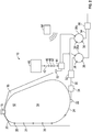
FIG. 1 is a schematic view of an embodiment of a potable water system; and -
FIG. 2 is a schematic view of another embodiment of a potable water system. - Referring now to
FIG. 1 , shown is an exemplary embodiment of potable water system (PWS) 10 for use in, for example, a passenger aircraft cabin. The PWS 10 includes awater storage tank 12, configured to contain a volume ofwater 14 or other fluid at ambient pressure, or at about 1 atmosphere. Thewater storage tank 12 is not constructed as a pressure vessel. In some embodiments, thewater storage tank 12 may have an interior volume of between 10 and 30 gallons. Thewater storage tank 12 may be of a substantially uniform shape, such as a cylinder, or as shown inFIG. 1 may be irregularly-shaped to fit or conform to anaircraft space 16 in which thewater storage tank 12 is located. Since it is not configured as a pressure vessel, thewater storage tank 12 may be formed from relatively low strength materials, such as lightweight metals, plastic, composite or rubber materials. Further, because thewater storage tank 12 is not constructed as a pressure vessel, it may be formed without internal baffles or internal or external ribs for strength, thereby simplifying construction of thewater storage tank 12 and reducing its cost compared to an equivalently-sized pressure vessel. - The
water storage tank 12 includes a storagetank fill port 18, in some embodiments located at anuppermost tank surface 20. Thewater storage tank 12 further includes astorage tank outlet 22, in some embodiments located at alowermost tank surface 24. Further, thewater storage tank 12 may include one or more storagetank level sensors 26, to detect a level of thewater volume 14 inside thewater storage tank 12. - The
water storage tank 12 is connected to apressure tank 28 via a storagetank output line 30. In some embodiments, thepressure tank 28 is a pressure vessel configured to hold a volume of between one quart and one gallon of water at any one time. The flow of water through the storagetank output line 30 from thewater storage tank 12 to thepressure tank 28 may be controlled by astorage output valve 32 located along the storagetank output line 30. While in the embodiment ofFIG. 1 , it is located along the storage tank output line, it is to be appreciated that in other embodiments thestorage output valve 32 may be positioned elsewhere, for example, at thewater storage tank 12 or at thepressure tank 28. Flow of water from thewater storage tank 12 and thepressure tank 28 may be achieved through gravity if, for example, thestorage tank outlet 22 is at a higher elevation that thepressure tank 28, or may be achieved via a motorizedpump 34 which may be located, for example, a submersible pump located inside of thewater storage tank 12 or may be located along storagetank output line 30. Thepressure tank 28 further includes one or more level sensors, for example afull level sensor 36 that indicates whenpressure tank 28 is full of water, and arefill level sensor 38 that indicates when the water level in thepressure tank 28 is at a level such that it should be refilled from thewater storage tank 12. - The
pressure tank 28 is pressurized to a pressure above ambient, or above 1 atmosphere through the introduction of air pressure from anair source 40. The air source may be, for example, bleed air from an aircraft engine or auxiliary power unit compressor (not shown). The air flow is urged from theair source 40 along anair line 42 and into thepressure tank 28, under the control of anair valve 44 located along theair line 42. Further components, such as anair pressure regulator 46 to control the air pressure entering theair line 42, acheck valve 48 to protect theair line 42 from reversing flow, and anair filter 50 to remove contaminants from the air, may also be located along theair line 42. Avent 52 is connected to theair valve 44 to allow for venting air from thepressure tank 28 to reduce the pressure in thepressure tank 28. Thepressure tank 28 is connected to a pressuretank output line 54 through awater valve 56 to provide a pressurized water supply upon request. - At initial start-up of the
PWS 10, thewater storage tank 12 is filled with thewater volume 14,controller 58 reads thelevel sensors pressure tank 28 and determines thatpressure tank 28 needs to be refilled.Storage output valve 32 is opened and thepressure tank 28 is filled untillevel sensor 36 indicates a full condition. Oncepressure tank 28 is filled,storage output valve 32 is closed andair valve 44 is opened, providing air pressure topressure tank 28 which is pressurized to the selected pressure. In some embodiments, the selected pressure of thepressure tank 28 is in the range of about 20 to 45 pounds per square inch (psi) (138 to 310 MPa). In operation,water valve 56 is opened allowing the flow of water frompressure tank 28 as needed. When the water level inpressure tank 28 reachesrefill level sensor 38, indicating need for a refill ofpressure tank 28,water valve 56 is closed, andair valve 44 is switched to a vent position, allowing the air frompressure tank 28 to proceed throughvent 52.Storage output valve 32 is opened to refillpressure tank 28 with water fromwater storage tank 12 and then closed to stop the flow of water from thewater storage tank 12 when the water in thepressure tank 28 reaches a selected level. Thepressure tank 28 is then re-pressurized viaair valve 44 andair line 42. Once refilled and re-pressurized,water valve 56 is opened, allowing for the use of water frompressure tank 28. - During the
time pressure tank 28 is vented, refilled and re-pressurized, the water supply will be unavailable for use. Alternatively, additional level sensors may be utilized inpressure tank 28 to refill thepressure tank 28 before it is fully emptied. Additionally, as shown inFIG. 2 , seamless continuous operation of thePWS 10 may be achieved by adding one or moreadditional pressure tanks 28. - Referring to
FIG. 2 , the embodiment shown includes two pressure tanks, 28a and 28b. It is to be appreciated, however, that other embodiments may include three ormore pressure tanks 28.Storage output valve 32 has four positions: fully closed, open to bothpressure tank 28a andpressure tank 28b, open topressure tank 28a and closed topressure tank 28b, and open topressure tank 28b and closed topressure tank 28a. Alternatively, individualstorage output valves 32 may be utilized. Theair valve 44 andwater valve 56 similarly have multiple operating positions. - Initial startup operation is similar to the embodiment of
FIG. 1 , except that bothpressure tanks storage output valve 32 and pressurized via theair valve 44 andair line 42. Thepressure tanks example pressure tank 28a, for use by actuation ofwater valve 56. When thelevel sensor 38 ofpressure tank 28a indicates a need to refillpressure tank 28a,controller 58switches water valve 56 to draw offpressure tank 28b, instead ofpressure tank 28a.Air valve 44 is switched to ventpressure tank 28a andstorage output valve 32 is switched to allow water to fillpressure tank 28a. Oncepressure tank 28a is refilled,storage output valve 32 is closed andair valve 44 is operated to pressurizepressure tank 28a. Whenpressure tank 28b reaches an empty level, a similar process is used to refillpressure tank 28b while water is drawn frompressure tank 28a for use. This process may be repeated as needed untilwater volume 14 inwater storage tank 12 is depleted. - The
potable water system 10 disclosed herein allows for lower cost and lower weight conformal water storage tank because there is no need for pressurization of the water storage tank, since the pressurization is performed at smaller pressure tanks downstream of the water storage tank. Further, in some embodiments, uninterrupted operation of the potable water system is provided by switching between two or more pressure tanks. - While the present disclosure has been described in detail in connection with only a limited number of embodiments, it should be readily understood that the present disclosure is not limited to such disclosed embodiments. Rather, the present disclosure can be modified to incorporate any number of variations, alterations, substitutions or equivalent arrangements not heretofore described, but which are commensurate in scope. Additionally, while various embodiments have been described, it is to be understood that aspects of the present disclosure may include only some of the described embodiments. Accordingly, the present disclosure is not to be seen as limited by the foregoing description, but is only limited by the scope of the appended claims.
Claims (15)
- A water supply system (10), comprising:a water storage tank (12) having a storage tank outlet (22), the water storage tank (12) configured to store a volume of water (14) at a first pressure;a pressure tank (28) in fluid communication with the water storage tank (12) and periodically fillable with water from the water storage tank (12); andan air source (40) fluidly connected to the pressure tank (28) to pressurize the volume of water in the pressure tank (28) to a second pressure greater than the first pressure; andand a pressure tank output line (54) fluidly connected to the pressure tank (28) to output water from the pressure tank (28).
- The water supply system of claim 1, wherein the first pressure is substantially ambient pressure.
- The water supply system of claim 1 or 2, further comprising a level sensor (38) disposed at the pressure tank (28) to detect when a water level in the pressure tank (28) is such that the pressure tank (28) is in need of refill.
- The water supply system of claim 3, wherein the level sensor (38) is operably connected to the water storage tank (12) to initiate refill of the pressure tank (28) from the water storage tank (12) when the level sensor (38) detects the pressure tank (28) is in need of refill.
- The water supply system of any preceding claim, wherein the pressure tank (28) is two pressure tanks (28a,b) arranged in parallel and flow through the pressure tank output line (54) is switchable between a first pressure tank (28a) of the two pressure tanks (28a,b) and a second pressure tank (28b) of the two pressure tanks (28b).
- The water supply system of claim 5, further comprising an air valve (44) operably connected to the air source (40) and the two pressure tanks (28a,b), to selectably admit pressurizing air to the first pressure tank (28a) and/or the second pressure tank (28b).
- The water supply system of claim 5 or 6, further comprising a storage output valve (32) operably connected to the water storage tank (12) and the two pressure tanks (28a,b) to selectably admit water into the first pressure tank (28a) and/or the second pressure tank (28b) from the water storage tank (12).
- The water supply system of any preceding claim, further comprising a pump (34) for urging water from the water storage tank (12) to the pressure tank (28).
- The water supply system of any preceding claim, wherein the water storage tank (12) is formed from one of a plastic or composite material.
- The water supply system of any preceding claim, wherein the water storage tank (12) is non-spherical and non-cylindrical.
- The water supply system of any preceding claim, wherein the second pressure is in the range of 20-45 pounds per square inch (138 to 310 MPa).
- A method of operating a water supply system (10), comprising:storing a volume of water (14) at a first pressure at a water storage tank (12);urging a portion of the volume of water (14) from the water storage tank (12) into a first pressure tank (28;28a);urging a volume of air from an air source (40) into the first pressure tank (28;28a) to pressurize the first pressure tank (28;28a) to a second pressure greater than the first pressure; andreleasing a flow of water from the first pressure tank (28;28a) via a pressure tank output line (54) fluidly connected to the first pressure tank (28;28a).
- The method of claim 12, further comprising;
detecting a water level at the first pressure tank (28;28a); and
refilling the first pressure tank (28;28a) from the water storage tank (12) based on the detected water level. - The method of claim 12, further comprising:urging a portion of the volume of water (14) from the water storage tank (12) into a second pressure tank (28b) arranged in parallel with the first pressure tank (28a);urging a volume of air from the air source (40) into the second pressure tank (28b) to pressurize the second pressure tank (28b) to a second pressure greater than the first pressure; andselectably releasing a flow of water from the first pressure tank (28a) and/or the second pressure tank (28b) via a pressure tank output line (54) fluidly connected to the first pressure tank (28a) and the second pressure tank (28b).
- The method of claim 14, further comprising selectably filling the first pressure tank (28a) and/or the second pressure tank (28b) from the water storage tank (12) through operation of a storage output valve (32) operably connected to the first pressure tank (28a) and the second pressure tank (28b).
Applications Claiming Priority (1)
| Application Number | Priority Date | Filing Date | Title |
|---|---|---|---|
| US15/071,860 US10590634B2 (en) | 2016-03-16 | 2016-03-16 | Pressurized potable water system with conformal shape water storage tank |
Publications (2)
| Publication Number | Publication Date |
|---|---|
| EP3219613A1 true EP3219613A1 (en) | 2017-09-20 |
| EP3219613B1 EP3219613B1 (en) | 2021-12-01 |
Family
ID=58360879
Family Applications (1)
| Application Number | Title | Priority Date | Filing Date |
|---|---|---|---|
| EP17161260.9A Active EP3219613B1 (en) | 2016-03-16 | 2017-03-16 | Pressurized potable water system with conformal shape water storage tank |
Country Status (3)
| Country | Link |
|---|---|
| US (1) | US10590634B2 (en) |
| EP (1) | EP3219613B1 (en) |
| CA (1) | CA2961054C (en) |
Cited By (2)
| Publication number | Priority date | Publication date | Assignee | Title |
|---|---|---|---|---|
| EP3666651A1 (en) * | 2018-12-12 | 2020-06-17 | Goodrich Corporation | Composite potable water tank and method of forming |
| EP3684580A4 (en) * | 2017-09-22 | 2021-06-23 | Murray, Howard | Water barrel |
Families Citing this family (12)
| Publication number | Priority date | Publication date | Assignee | Title |
|---|---|---|---|---|
| US10703481B2 (en) * | 2017-08-29 | 2020-07-07 | Goodrich Corporation | Conformable tank with sandwich structure walls |
| US11091266B2 (en) * | 2017-08-29 | 2021-08-17 | Goodrich Corporation | Conformable tank fabricated using additive manufacturing |
| US11939105B2 (en) | 2017-08-29 | 2024-03-26 | Goodrich Corporation | 3D woven conformable tank |
| US10816138B2 (en) | 2017-09-15 | 2020-10-27 | Goodrich Corporation | Manufacture of a conformable pressure vessel |
| US20210031923A1 (en) * | 2019-07-30 | 2021-02-04 | B/E Aerospace, Inc. | Aircraft Galley Plumbing System |
| US20210033206A1 (en) * | 2019-07-30 | 2021-02-04 | B/E Aerospace, Inc. | Four-Way Rotary Valve for an Aircraft Galley Plumbing System |
| CN111733933B (en) * | 2020-07-02 | 2021-05-18 | 广州百畅信息科技有限公司 | Security protection monitoring thermodynamic diagram statistical system |
| US11826776B2 (en) | 2020-07-21 | 2023-11-28 | Goodrich Corporation | Liner systems and methods for high-pressure fluid vessels |
| CN113073711B (en) * | 2021-04-23 | 2022-09-06 | 海丝埃睿迪数字科技有限公司 | Secondary water supply system and method based on big data |
| EP4389602A1 (en) * | 2022-12-20 | 2024-06-26 | Airbus Operations GmbH | Water supply and distribution system on-board an aircraft and method for operating such system |
| EP4389601A1 (en) * | 2022-12-20 | 2024-06-26 | Airbus Operations GmbH | Water supply and distribution system on-board an aircraft and method for operating such system |
| DE102023109511B3 (en) * | 2023-04-14 | 2024-07-11 | Alexander Mayerhofer | Medium installation of a vehicle and such |
Citations (5)
| Publication number | Priority date | Publication date | Assignee | Title |
|---|---|---|---|---|
| US4063315A (en) * | 1974-12-13 | 1977-12-20 | The Boeing Company | Vacuum toilet system |
| US5261440A (en) * | 1992-01-31 | 1993-11-16 | Deutsche Aerospace Airbus Gmbh | Water supply system for an aircraft |
| US5303739A (en) * | 1991-09-30 | 1994-04-19 | Deutsche Aerospace Airbus Gmbh | Fresh water supply system for an aircraft |
| US20070069078A1 (en) * | 2005-09-21 | 2007-03-29 | Airbus Deutschland Gmbh | Water-wastewater module for aircraft |
| CN201330438Y (en) * | 2008-12-30 | 2009-10-21 | 安徽金诚汽车科技有限公司 | Vehicle toilet air blasting system |
Family Cites Families (14)
| Publication number | Priority date | Publication date | Assignee | Title |
|---|---|---|---|---|
| US3788343A (en) * | 1972-07-03 | 1974-01-29 | Bar O Matic Sales Co | Liquid dispensing apparatus |
| DE3715759A1 (en) * | 1987-05-12 | 1988-12-01 | Messerschmitt Boelkow Blohm | WATER SUPPLY ARRANGEMENT, IN PARTICULAR ON BOARD A PLANE |
| US5358009A (en) * | 1991-11-06 | 1994-10-25 | Cambell Gary J | Liquid storage vessel venting system |
| US5992684A (en) * | 1996-01-26 | 1999-11-30 | Russell; Larry L. | Water dispensing device |
| US5901879A (en) * | 1997-10-17 | 1999-05-11 | Duhaime; Richard | Precision liquid dispenser device |
| US6463956B2 (en) * | 1998-09-29 | 2002-10-15 | International Water-Guard Industries Inc. | Method of water distribution and apparatus therefor |
| DE102005006136B4 (en) * | 2005-02-10 | 2010-02-04 | Airbus Deutschland Gmbh | Airplane with gray water utilization system |
| US20070130684A1 (en) * | 2005-12-14 | 2007-06-14 | Watts Timothy M | Trailered mobile showering facility |
| FR2912822B1 (en) * | 2007-02-20 | 2009-05-08 | Serac Group Soc Par Actions Si | METHOD AND DEVICE FOR PRESSURE CONTROL IN A TANK |
| DE102007018549A1 (en) * | 2007-04-19 | 2008-10-30 | Airbus Deutschland Gmbh | Vacuum toilet system for waste water transport and sewage collection in an airplane |
| CA2686836C (en) * | 2008-12-01 | 2017-04-11 | International Water-Guard Industries, Inc. | Water distribution system with dual use water treatment unit |
| KR20110109088A (en) * | 2010-03-30 | 2011-10-06 | 웅진코웨이주식회사 | Apparatus for storing and discharging water |
| DE102011109943A1 (en) * | 2011-08-10 | 2013-02-14 | Airbus Operations Gmbh | Pressure supply for a water system |
| US10334776B2 (en) * | 2013-06-12 | 2019-07-02 | Agco Corporation | Method and system having an intermediate holding vessel for combining chemical injection substances for a spray system |
-
2016
- 2016-03-16 US US15/071,860 patent/US10590634B2/en active Active
-
2017
- 2017-03-13 CA CA2961054A patent/CA2961054C/en active Active
- 2017-03-16 EP EP17161260.9A patent/EP3219613B1/en active Active
Patent Citations (5)
| Publication number | Priority date | Publication date | Assignee | Title |
|---|---|---|---|---|
| US4063315A (en) * | 1974-12-13 | 1977-12-20 | The Boeing Company | Vacuum toilet system |
| US5303739A (en) * | 1991-09-30 | 1994-04-19 | Deutsche Aerospace Airbus Gmbh | Fresh water supply system for an aircraft |
| US5261440A (en) * | 1992-01-31 | 1993-11-16 | Deutsche Aerospace Airbus Gmbh | Water supply system for an aircraft |
| US20070069078A1 (en) * | 2005-09-21 | 2007-03-29 | Airbus Deutschland Gmbh | Water-wastewater module for aircraft |
| CN201330438Y (en) * | 2008-12-30 | 2009-10-21 | 安徽金诚汽车科技有限公司 | Vehicle toilet air blasting system |
Cited By (2)
| Publication number | Priority date | Publication date | Assignee | Title |
|---|---|---|---|---|
| EP3684580A4 (en) * | 2017-09-22 | 2021-06-23 | Murray, Howard | Water barrel |
| EP3666651A1 (en) * | 2018-12-12 | 2020-06-17 | Goodrich Corporation | Composite potable water tank and method of forming |
Also Published As
| Publication number | Publication date |
|---|---|
| CA2961054A1 (en) | 2017-09-16 |
| US10590634B2 (en) | 2020-03-17 |
| CA2961054C (en) | 2026-03-31 |
| EP3219613B1 (en) | 2021-12-01 |
| BR102017005220A2 (en) | 2017-09-19 |
| US20170268206A1 (en) | 2017-09-21 |
Similar Documents
| Publication | Publication Date | Title |
|---|---|---|
| EP3219613B1 (en) | Pressurized potable water system with conformal shape water storage tank | |
| USRE35874E (en) | LNG delivery system for gas powered vehicles | |
| CN205350853U (en) | Cryrogenic fluid conveying system | |
| CA2830709C (en) | Fuel storage device, aircraft and method | |
| US9873519B2 (en) | Tanker aircraft capacity extension system and method | |
| NL1036706C2 (en) | INFLATABLE ELEMENT FOR USE IN THE INSIDE OF A FUEL HOLDER OF A VEHICLE, VESSEL OR AIRCRAFT. | |
| US20140137572A1 (en) | Natural Gas Vehicle Vented Gas Capture System | |
| US20170114961A1 (en) | Valve unit for gas container with a pressure-indicating or autonomy-indication device near the top | |
| EP3918188B1 (en) | Oil storage and filtration system | |
| US10850971B1 (en) | Mobile fuel dispenser | |
| EP3102832A1 (en) | Foot valve for submergible pumps | |
| US11617971B2 (en) | Method for degassing flowable fluids | |
| CN106460874A (en) | Hydraulic system | |
| EP4303174A1 (en) | System for preventing the formation of fuel vapour | |
| CN101643112A (en) | Conversion cabin device for underwater vehicle personnel to get out of cabin | |
| US9884754B2 (en) | Dispensing gun | |
| US20200182409A1 (en) | Cryogenic Liquid Dispensing System Having a Raised Basin | |
| US20230287665A1 (en) | Buffer for storing liquid at a consumer pressure | |
| BR102017005220B1 (en) | WATER SUPPLY SYSTEM, AND METHOD OF OPERATION OF A WATER SUPPLY SYSTEM | |
| KR20120091658A (en) | System for main air compressing in vessel and the controlling method thereof | |
| EP0861206B1 (en) | Filling of tanks with volatile liquids | |
| US11377225B2 (en) | Fuel supply system for aerial vehicle | |
| PL1676063T3 (en) | Overfill protection device | |
| KR102941853B1 (en) | Apparatus and method for dispensing a cryogenic fluid | |
| RU150329U1 (en) | FUEL AIRCRAFT SYSTEM (OPTIONS) |
Legal Events
| Date | Code | Title | Description |
|---|---|---|---|
| PUAI | Public reference made under article 153(3) epc to a published international application that has entered the european phase |
Free format text: ORIGINAL CODE: 0009012 |
|
| STAA | Information on the status of an ep patent application or granted ep patent |
Free format text: STATUS: THE APPLICATION HAS BEEN PUBLISHED |
|
| AK | Designated contracting states |
Kind code of ref document: A1 Designated state(s): AL AT BE BG CH CY CZ DE DK EE ES FI FR GB GR HR HU IE IS IT LI LT LU LV MC MK MT NL NO PL PT RO RS SE SI SK SM TR |
|
| AX | Request for extension of the european patent |
Extension state: BA ME |
|
| STAA | Information on the status of an ep patent application or granted ep patent |
Free format text: STATUS: REQUEST FOR EXAMINATION WAS MADE |
|
| 17P | Request for examination filed |
Effective date: 20180320 |
|
| RBV | Designated contracting states (corrected) |
Designated state(s): AL AT BE BG CH CY CZ DE DK EE ES FI FR GB GR HR HU IE IS IT LI LT LU LV MC MK MT NL NO PL PT RO RS SE SI SK SM TR |
|
| STAA | Information on the status of an ep patent application or granted ep patent |
Free format text: STATUS: EXAMINATION IS IN PROGRESS |
|
| 17Q | First examination report despatched |
Effective date: 20190820 |
|
| GRAP | Despatch of communication of intention to grant a patent |
Free format text: ORIGINAL CODE: EPIDOSNIGR1 |
|
| RIC1 | Information provided on ipc code assigned before grant |
Ipc: B64D 11/04 20060101AFI20210519BHEP Ipc: B61D 35/00 20060101ALI20210519BHEP Ipc: B60R 15/02 20060101ALI20210519BHEP Ipc: B60R 15/04 20060101ALI20210519BHEP Ipc: E03B 7/07 20060101ALI20210519BHEP Ipc: E03B 11/02 20060101ALI20210519BHEP Ipc: B64D 11/00 20060101ALI20210519BHEP Ipc: B64D 11/02 20060101ALI20210519BHEP |
|
| STAA | Information on the status of an ep patent application or granted ep patent |
Free format text: STATUS: GRANT OF PATENT IS INTENDED |
|
| INTG | Intention to grant announced |
Effective date: 20210624 |
|
| GRAS | Grant fee paid |
Free format text: ORIGINAL CODE: EPIDOSNIGR3 |
|
| GRAA | (expected) grant |
Free format text: ORIGINAL CODE: 0009210 |
|
| STAA | Information on the status of an ep patent application or granted ep patent |
Free format text: STATUS: THE PATENT HAS BEEN GRANTED |
|
| AK | Designated contracting states |
Kind code of ref document: B1 Designated state(s): AL AT BE BG CH CY CZ DE DK EE ES FI FR GB GR HR HU IE IS IT LI LT LU LV MC MK MT NL NO PL PT RO RS SE SI SK SM TR |
|
| REG | Reference to a national code |
Ref country code: GB Ref legal event code: FG4D |
|
| REG | Reference to a national code |
Ref country code: AT Ref legal event code: REF Ref document number: 1451537 Country of ref document: AT Kind code of ref document: T Effective date: 20211215 Ref country code: CH Ref legal event code: EP |
|
| REG | Reference to a national code |
Ref country code: IE Ref legal event code: FG4D |
|
| REG | Reference to a national code |
Ref country code: DE Ref legal event code: R096 Ref document number: 602017050043 Country of ref document: DE |
|
| REG | Reference to a national code |
Ref country code: LT Ref legal event code: MG9D |
|
| REG | Reference to a national code |
Ref country code: NL Ref legal event code: MP Effective date: 20211201 |
|
| REG | Reference to a national code |
Ref country code: AT Ref legal event code: MK05 Ref document number: 1451537 Country of ref document: AT Kind code of ref document: T Effective date: 20211201 |
|
| PG25 | Lapsed in a contracting state [announced via postgrant information from national office to epo] |
Ref country code: RS Free format text: LAPSE BECAUSE OF FAILURE TO SUBMIT A TRANSLATION OF THE DESCRIPTION OR TO PAY THE FEE WITHIN THE PRESCRIBED TIME-LIMIT Effective date: 20211201 Ref country code: LT Free format text: LAPSE BECAUSE OF FAILURE TO SUBMIT A TRANSLATION OF THE DESCRIPTION OR TO PAY THE FEE WITHIN THE PRESCRIBED TIME-LIMIT Effective date: 20211201 Ref country code: FI Free format text: LAPSE BECAUSE OF FAILURE TO SUBMIT A TRANSLATION OF THE DESCRIPTION OR TO PAY THE FEE WITHIN THE PRESCRIBED TIME-LIMIT Effective date: 20211201 Ref country code: BG Free format text: LAPSE BECAUSE OF FAILURE TO SUBMIT A TRANSLATION OF THE DESCRIPTION OR TO PAY THE FEE WITHIN THE PRESCRIBED TIME-LIMIT Effective date: 20220301 Ref country code: AT Free format text: LAPSE BECAUSE OF FAILURE TO SUBMIT A TRANSLATION OF THE DESCRIPTION OR TO PAY THE FEE WITHIN THE PRESCRIBED TIME-LIMIT Effective date: 20211201 |
|
| PG25 | Lapsed in a contracting state [announced via postgrant information from national office to epo] |
Ref country code: SE Free format text: LAPSE BECAUSE OF FAILURE TO SUBMIT A TRANSLATION OF THE DESCRIPTION OR TO PAY THE FEE WITHIN THE PRESCRIBED TIME-LIMIT Effective date: 20211201 Ref country code: PL Free format text: LAPSE BECAUSE OF FAILURE TO SUBMIT A TRANSLATION OF THE DESCRIPTION OR TO PAY THE FEE WITHIN THE PRESCRIBED TIME-LIMIT Effective date: 20211201 Ref country code: NO Free format text: LAPSE BECAUSE OF FAILURE TO SUBMIT A TRANSLATION OF THE DESCRIPTION OR TO PAY THE FEE WITHIN THE PRESCRIBED TIME-LIMIT Effective date: 20220301 Ref country code: LV Free format text: LAPSE BECAUSE OF FAILURE TO SUBMIT A TRANSLATION OF THE DESCRIPTION OR TO PAY THE FEE WITHIN THE PRESCRIBED TIME-LIMIT Effective date: 20211201 Ref country code: HR Free format text: LAPSE BECAUSE OF FAILURE TO SUBMIT A TRANSLATION OF THE DESCRIPTION OR TO PAY THE FEE WITHIN THE PRESCRIBED TIME-LIMIT Effective date: 20211201 Ref country code: GR Free format text: LAPSE BECAUSE OF FAILURE TO SUBMIT A TRANSLATION OF THE DESCRIPTION OR TO PAY THE FEE WITHIN THE PRESCRIBED TIME-LIMIT Effective date: 20220302 Ref country code: ES Free format text: LAPSE BECAUSE OF FAILURE TO SUBMIT A TRANSLATION OF THE DESCRIPTION OR TO PAY THE FEE WITHIN THE PRESCRIBED TIME-LIMIT Effective date: 20211201 |
|
| PG25 | Lapsed in a contracting state [announced via postgrant information from national office to epo] |
Ref country code: NL Free format text: LAPSE BECAUSE OF FAILURE TO SUBMIT A TRANSLATION OF THE DESCRIPTION OR TO PAY THE FEE WITHIN THE PRESCRIBED TIME-LIMIT Effective date: 20211201 |
|
| PG25 | Lapsed in a contracting state [announced via postgrant information from national office to epo] |
Ref country code: SM Free format text: LAPSE BECAUSE OF FAILURE TO SUBMIT A TRANSLATION OF THE DESCRIPTION OR TO PAY THE FEE WITHIN THE PRESCRIBED TIME-LIMIT Effective date: 20211201 Ref country code: SK Free format text: LAPSE BECAUSE OF FAILURE TO SUBMIT A TRANSLATION OF THE DESCRIPTION OR TO PAY THE FEE WITHIN THE PRESCRIBED TIME-LIMIT Effective date: 20211201 Ref country code: RO Free format text: LAPSE BECAUSE OF FAILURE TO SUBMIT A TRANSLATION OF THE DESCRIPTION OR TO PAY THE FEE WITHIN THE PRESCRIBED TIME-LIMIT Effective date: 20211201 Ref country code: PT Free format text: LAPSE BECAUSE OF FAILURE TO SUBMIT A TRANSLATION OF THE DESCRIPTION OR TO PAY THE FEE WITHIN THE PRESCRIBED TIME-LIMIT Effective date: 20220401 Ref country code: EE Free format text: LAPSE BECAUSE OF FAILURE TO SUBMIT A TRANSLATION OF THE DESCRIPTION OR TO PAY THE FEE WITHIN THE PRESCRIBED TIME-LIMIT Effective date: 20211201 Ref country code: CZ Free format text: LAPSE BECAUSE OF FAILURE TO SUBMIT A TRANSLATION OF THE DESCRIPTION OR TO PAY THE FEE WITHIN THE PRESCRIBED TIME-LIMIT Effective date: 20211201 |
|
| REG | Reference to a national code |
Ref country code: DE Ref legal event code: R097 Ref document number: 602017050043 Country of ref document: DE |
|
| PG25 | Lapsed in a contracting state [announced via postgrant information from national office to epo] |
Ref country code: IS Free format text: LAPSE BECAUSE OF FAILURE TO SUBMIT A TRANSLATION OF THE DESCRIPTION OR TO PAY THE FEE WITHIN THE PRESCRIBED TIME-LIMIT Effective date: 20220401 |
|
| PLBE | No opposition filed within time limit |
Free format text: ORIGINAL CODE: 0009261 |
|
| STAA | Information on the status of an ep patent application or granted ep patent |
Free format text: STATUS: NO OPPOSITION FILED WITHIN TIME LIMIT |
|
| PG25 | Lapsed in a contracting state [announced via postgrant information from national office to epo] |
Ref country code: MC Free format text: LAPSE BECAUSE OF FAILURE TO SUBMIT A TRANSLATION OF THE DESCRIPTION OR TO PAY THE FEE WITHIN THE PRESCRIBED TIME-LIMIT Effective date: 20211201 Ref country code: DK Free format text: LAPSE BECAUSE OF FAILURE TO SUBMIT A TRANSLATION OF THE DESCRIPTION OR TO PAY THE FEE WITHIN THE PRESCRIBED TIME-LIMIT Effective date: 20211201 Ref country code: AL Free format text: LAPSE BECAUSE OF FAILURE TO SUBMIT A TRANSLATION OF THE DESCRIPTION OR TO PAY THE FEE WITHIN THE PRESCRIBED TIME-LIMIT Effective date: 20211201 |
|
| REG | Reference to a national code |
Ref country code: CH Ref legal event code: PL |
|
| 26N | No opposition filed |
Effective date: 20220902 |
|
| PG25 | Lapsed in a contracting state [announced via postgrant information from national office to epo] |
Ref country code: SI Free format text: LAPSE BECAUSE OF FAILURE TO SUBMIT A TRANSLATION OF THE DESCRIPTION OR TO PAY THE FEE WITHIN THE PRESCRIBED TIME-LIMIT Effective date: 20211201 |
|
| REG | Reference to a national code |
Ref country code: BE Ref legal event code: MM Effective date: 20220331 |
|
| PG25 | Lapsed in a contracting state [announced via postgrant information from national office to epo] |
Ref country code: LU Free format text: LAPSE BECAUSE OF NON-PAYMENT OF DUE FEES Effective date: 20220316 Ref country code: LI Free format text: LAPSE BECAUSE OF NON-PAYMENT OF DUE FEES Effective date: 20220331 Ref country code: IE Free format text: LAPSE BECAUSE OF NON-PAYMENT OF DUE FEES Effective date: 20220316 Ref country code: CH Free format text: LAPSE BECAUSE OF NON-PAYMENT OF DUE FEES Effective date: 20220331 |
|
| PG25 | Lapsed in a contracting state [announced via postgrant information from national office to epo] |
Ref country code: BE Free format text: LAPSE BECAUSE OF NON-PAYMENT OF DUE FEES Effective date: 20220331 |
|
| PG25 | Lapsed in a contracting state [announced via postgrant information from national office to epo] |
Ref country code: IT Free format text: LAPSE BECAUSE OF FAILURE TO SUBMIT A TRANSLATION OF THE DESCRIPTION OR TO PAY THE FEE WITHIN THE PRESCRIBED TIME-LIMIT Effective date: 20211201 |
|
| P01 | Opt-out of the competence of the unified patent court (upc) registered |
Effective date: 20230522 |
|
| PG25 | Lapsed in a contracting state [announced via postgrant information from national office to epo] |
Ref country code: HU Free format text: LAPSE BECAUSE OF FAILURE TO SUBMIT A TRANSLATION OF THE DESCRIPTION OR TO PAY THE FEE WITHIN THE PRESCRIBED TIME-LIMIT; INVALID AB INITIO Effective date: 20170316 |
|
| PG25 | Lapsed in a contracting state [announced via postgrant information from national office to epo] |
Ref country code: MK Free format text: LAPSE BECAUSE OF FAILURE TO SUBMIT A TRANSLATION OF THE DESCRIPTION OR TO PAY THE FEE WITHIN THE PRESCRIBED TIME-LIMIT Effective date: 20211201 Ref country code: CY Free format text: LAPSE BECAUSE OF FAILURE TO SUBMIT A TRANSLATION OF THE DESCRIPTION OR TO PAY THE FEE WITHIN THE PRESCRIBED TIME-LIMIT Effective date: 20211201 |
|
| PG25 | Lapsed in a contracting state [announced via postgrant information from national office to epo] |
Ref country code: MT Free format text: LAPSE BECAUSE OF FAILURE TO SUBMIT A TRANSLATION OF THE DESCRIPTION OR TO PAY THE FEE WITHIN THE PRESCRIBED TIME-LIMIT Effective date: 20211201 |
|
| PG25 | Lapsed in a contracting state [announced via postgrant information from national office to epo] |
Ref country code: TR Free format text: LAPSE BECAUSE OF FAILURE TO SUBMIT A TRANSLATION OF THE DESCRIPTION OR TO PAY THE FEE WITHIN THE PRESCRIBED TIME-LIMIT Effective date: 20211201 |
|
| PGFP | Annual fee paid to national office [announced via postgrant information from national office to epo] |
Ref country code: GB Payment date: 20260220 Year of fee payment: 10 |
|
| PGFP | Annual fee paid to national office [announced via postgrant information from national office to epo] |
Ref country code: DE Payment date: 20260219 Year of fee payment: 10 |
|
| PGFP | Annual fee paid to national office [announced via postgrant information from national office to epo] |
Ref country code: FR Payment date: 20260219 Year of fee payment: 10 |