EP3219542A2 - Transportation vehicle - Google Patents
Transportation vehicle Download PDFInfo
- Publication number
- EP3219542A2 EP3219542A2 EP17152393.9A EP17152393A EP3219542A2 EP 3219542 A2 EP3219542 A2 EP 3219542A2 EP 17152393 A EP17152393 A EP 17152393A EP 3219542 A2 EP3219542 A2 EP 3219542A2
- Authority
- EP
- European Patent Office
- Prior art keywords
- vessel
- lubricant
- hoist cylinder
- hoist
- valve
- Prior art date
- Legal status (The legal status is an assumption and is not a legal conclusion. Google has not performed a legal analysis and makes no representation as to the accuracy of the status listed.)
- Granted
Links
- 239000000314 lubricant Substances 0.000 claims abstract description 65
- 239000010720 hydraulic oil Substances 0.000 claims abstract description 49
- 238000001514 detection method Methods 0.000 claims abstract description 13
- 230000005484 gravity Effects 0.000 claims description 2
- 239000004519 grease Substances 0.000 description 77
- 239000003921 oil Substances 0.000 description 76
- 230000007935 neutral effect Effects 0.000 description 14
- 239000011435 rock Substances 0.000 description 9
- 238000010586 diagram Methods 0.000 description 6
- 238000005299 abrasion Methods 0.000 description 4
- 239000000725 suspension Substances 0.000 description 4
- 238000007599 discharging Methods 0.000 description 3
- 230000000694 effects Effects 0.000 description 3
- 230000032258 transport Effects 0.000 description 3
- 239000006096 absorbing agent Substances 0.000 description 2
- 238000006243 chemical reaction Methods 0.000 description 2
- 230000008602 contraction Effects 0.000 description 2
- 238000005461 lubrication Methods 0.000 description 2
- 230000007246 mechanism Effects 0.000 description 2
- 239000012466 permeate Substances 0.000 description 2
- 230000004044 response Effects 0.000 description 2
- 230000035939 shock Effects 0.000 description 2
- 239000007858 starting material Substances 0.000 description 2
- 230000001133 acceleration Effects 0.000 description 1
- 230000007423 decrease Effects 0.000 description 1
- 230000003247 decreasing effect Effects 0.000 description 1
- -1 earth Substances 0.000 description 1
- 238000012986 modification Methods 0.000 description 1
- 230000004048 modification Effects 0.000 description 1
- 230000002093 peripheral effect Effects 0.000 description 1
- 239000004576 sand Substances 0.000 description 1
- 238000000638 solvent extraction Methods 0.000 description 1
Images




Classifications
-
- B—PERFORMING OPERATIONS; TRANSPORTING
- B60—VEHICLES IN GENERAL
- B60P—VEHICLES ADAPTED FOR LOAD TRANSPORTATION OR TO TRANSPORT, TO CARRY, OR TO COMPRISE SPECIAL LOADS OR OBJECTS
- B60P1/00—Vehicles predominantly for transporting loads and modified to facilitate loading, consolidating the load, or unloading
- B60P1/04—Vehicles predominantly for transporting loads and modified to facilitate loading, consolidating the load, or unloading with a tipping movement of load-transporting element
- B60P1/16—Vehicles predominantly for transporting loads and modified to facilitate loading, consolidating the load, or unloading with a tipping movement of load-transporting element actuated by fluid-operated mechanisms
- B60P1/22—Vehicles predominantly for transporting loads and modified to facilitate loading, consolidating the load, or unloading with a tipping movement of load-transporting element actuated by fluid-operated mechanisms with cables, chains, or the like
-
- B—PERFORMING OPERATIONS; TRANSPORTING
- B60—VEHICLES IN GENERAL
- B60P—VEHICLES ADAPTED FOR LOAD TRANSPORTATION OR TO TRANSPORT, TO CARRY, OR TO COMPRISE SPECIAL LOADS OR OBJECTS
- B60P1/00—Vehicles predominantly for transporting loads and modified to facilitate loading, consolidating the load, or unloading
- B60P1/04—Vehicles predominantly for transporting loads and modified to facilitate loading, consolidating the load, or unloading with a tipping movement of load-transporting element
- B60P1/16—Vehicles predominantly for transporting loads and modified to facilitate loading, consolidating the load, or unloading with a tipping movement of load-transporting element actuated by fluid-operated mechanisms
-
- B—PERFORMING OPERATIONS; TRANSPORTING
- B60—VEHICLES IN GENERAL
- B60P—VEHICLES ADAPTED FOR LOAD TRANSPORTATION OR TO TRANSPORT, TO CARRY, OR TO COMPRISE SPECIAL LOADS OR OBJECTS
- B60P1/00—Vehicles predominantly for transporting loads and modified to facilitate loading, consolidating the load, or unloading
- B60P1/04—Vehicles predominantly for transporting loads and modified to facilitate loading, consolidating the load, or unloading with a tipping movement of load-transporting element
- B60P1/16—Vehicles predominantly for transporting loads and modified to facilitate loading, consolidating the load, or unloading with a tipping movement of load-transporting element actuated by fluid-operated mechanisms
- B60P1/162—Vehicles predominantly for transporting loads and modified to facilitate loading, consolidating the load, or unloading with a tipping movement of load-transporting element actuated by fluid-operated mechanisms the hydraulic system itself
-
- B—PERFORMING OPERATIONS; TRANSPORTING
- B60—VEHICLES IN GENERAL
- B60R—VEHICLES, VEHICLE FITTINGS, OR VEHICLE PARTS, NOT OTHERWISE PROVIDED FOR
- B60R17/00—Arrangements or adaptations of lubricating systems or devices
- B60R17/02—Systems, e.g. central lubrication systems
Definitions
- the present invention relates to a haulage vehicle.
- a dump truck with a vessel provided to be able to rise and fall on a vehicle.
- the dump truck transports a large amount of transportation objects such as crushed rocks, earth, sand and so on loaded in the vessel.
- the dump truck is provided with a hoist cylinder that is telescopically provided between the vessel and the vehicle and that extends to tilt the vessel when discharging the transportation objects from the vessel, as described in International Application Publication No. WO2008/099691 .
- the hoist cylinder is connected at its lower end with a hoist shaft provided in the vehicle and is connected at its upper end with the vessel by means of a pin.
- the hoist cylinder has a rod head disposed at its lower end, the rod head is provided with a bore through which the hoist shaft passes, and a cylindrical bushing is arranged in the bore.
- the hoist shaft is mounted on the rod head through the cylindrical bushing.
- the inside diameter of the bushing provided on the rod head is set to be smaller slightly than the outside diameter of the hoist shaft.
- the hoist shaft supports the dead weight of those including the vessel and the hoist cylinder. That is, the hoist shaft supports the load directed downward (toward the ground under the vehicle). In this state, a tight contact is held between an internal surface upper part of the bushing and a surface upper part of the hoist shaft, and this gives rise to a problem that it is unable to supply lubricant to the tight contact portion between the hoist shaft and the bushing and hence, that the upper parts of the hoist shaft and the bushing abrade easier than other parts thereof.
- a haulage vehicle which is provided with: a vessel pivotably provided relative to a vehicle; a hoist cylinder provided telescopically between the vessel and the vehicle; a hydraulic power source that supplies the host cylinder with hydraulic oil; and a valve provided between the hydraulic power source and the hoist cylinder for controlling the flow of hydraulic oil supplied to the hoist cylinder
- the haulage vehicle is further provided with: a bushing provided at one end portion of the hoist cylinder; a hoist shaft provided in the vehicle and mounted in a through bore of the bushing; a lubricant supplier that supplies lubricant to a clearance between a surface of the hoist shaft and an internal surface of the through bore of the bushing; a seating detection device that detects whether the vessel is seated on the vehicle or not; and/or a controller that when the vessel is seated on the vehicle, controls the valve to make the hoist cylinder contract and also controls the lubricant supplier to supply lubricant to the clearance.
- the hoist shaft and the bushing of the hoist cylinder it is possible to restrain the hoist shaft and the bushing of the hoist cylinder from abrading, so that the hoist shaft and the bushing can be extended in service life.
- FIG. 1 is a side view (as viewed from left side of the vehicle) of a dump truck 1 according to one embodiment of the present invention.
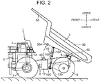
- FIG. 2 is a side view (as viewed from left side of the vehicle) of the dump truck 1 with a vessel 3 tilted obliquely rearward.
- the front-rear direction and the upper-lower (upward-downward) direction are prescribed as indicated in these figures.
- the dump truck 1 is provided with a self-propellable vehicle, the vessel 3 as a loading platform that is provided to be able to rise and fall (i.e., to be pivotable) on a vehicle frame 2 constituting the vehicle, a cab (driver's cab) 6 provided at the front part of the vehicle frame 2, and hoist cylinders 10 that pivotably move the vessel 3 (i.e., that make the vessel 3 rise or fall) in the upward-downward direction.
- the vessel 3 as a loading platform that is provided to be able to rise and fall (i.e., to be pivotable) on a vehicle frame 2 constituting the vehicle
- a cab (driver's cab) 6 provided at the front part of the vehicle frame 2
- hoist cylinders 10 that pivotably move the vessel 3 (i.e., that make the vessel 3 rise or fall) in the upward-downward direction.
- the vessel 3 is formed as , for example, a giant-sized container of 10-13 meters long in entire length for loading thereon a large amount of heavy transportation objects such as crushed rocks and the like (hereafter referred to as crushed rocks 4).
- the vessel 3 is integrally provided with a container section 3B for containing the crushed rocks 4 and a canopy section 3A which is provided at the front side of the container section 3B and which covers the upper part of the cab 6 to protect the cab 6 from scattering rocks.
- a bottom part on the rear side of the vessel 3 is coupled with the vehicle frame 2 to be pivotable (to be able to rise and fall) relative to the vehicle frame 2 through a connecting pin 5 provided in the vicinity of the rear end of the vehicle frame 2.
- the vessel 3 rises or falls so that the canopy section 3A on the front side of the vessel 3 pivots in the upward-downward about the connecting pin 5 serving as a fulcrum.
- the vessel 3 is pivoted between a transportation position shown in FIG. 1 and a dumping position shown in FIG. 2 .
- the crushed rocks 4 loaded in the vessel 3 are discharged to a predetermined pickup/collection point as they slip down from the vessel 3 that is tilted obliquely rearward to have the rear side positioned below the front side as shown in FIG. 2 .
- the vessel 3 is held in the seated state with the bottom portion on the front side of the container section 3B seated on a chassis table (not shown) of the vehicle frame 2.
- a driver's seat on which an operator is seated, a starter switch for starting an engine 9, an acceleration pedal for causing the vehicle to travel, a brake pedal for giving the vehicle a brake force, a steering handle for steering operation (all not shown) and an operating lever device 28 (refer to FIG. 4 ) for making the vessel 3 to rise or fall.
- the dump truck 1 is provided with front wheels 7 and rear wheels 8.
- the front wheels 7 constitute steered wheels which are steerable (can be given a steering operation) by the operator of the dump truck 1.
- front wheel side suspensions 7A constituted by hydraulic shock absorbers, and the front part side of the vehicle frame 2 is supported by the front wheel side suspensions 7A.
- the rear wheels 8 constitute drive wheels of the dump truck 1 and are rotationally driven by a traveling drive device (not shown). Between the rear wheels 8 and the rear part of the vehicle frame 2, there are provide rear wheel side suspensions 8A constituted by hydraulic shock absorbers and the like, so that the rear part side of the vehicle frame 2 is supported by the rear wheel side suspensions 8A.
- the outside diameter of the front wheels 7 and the rear wheels 8 is up to the range of 2 to 4 meters.
- the engine 9 is provided as a prime mover.
- the engine 9 is constituted by, for example, a large-sized diesel engine and the like.
- Each hoist cylinder 10 is a hydraulic cylinder of a multistage type (e.g., a two-stage type).
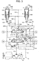
- FIG. 3 shows a hydraulic circuit diagram for driving the hoist cylinders 10.
- the hoist cylinders 10 are paired to have the same configuration.
- the hoist cylinders 10 are each provided with a cylindrical outer tube portion 10A, a cylindrical inner tube portion 10B provided telescopically inside the outer tube portion 10A and partitioning the interior of the outer tube portion 10A into an upper side oil chamber A and a lower side oil chamber B, and a piston rod 10C provided telescopically in the interior of the inner tube portion 10B.
- the pair of the hoist cylinders 10 are identical in its configuration and operation as well as in connection relation with the hydraulic circuit shown in FIG. 3 . Therefore, as a matter of convenience, the following description will be directed typically to one only of the hoist cylinders 10 unless otherwise specified to the contrary, and such description directed to one hoist cylinder 10 will be equally applied to the other hoist cylinder 10.
- the hoist cylinder 10 extends the piston rod 10C when supplied at the oil chamber A with hydraulic oil from the main pump 11 and when discharging hydraulic oil from the oil chamber B, and makes the piston rod 10C contract when supplied at the oil chamber B with hydraulic oil from the main pump 11 and when discharging hydraulic oil from the oil chamber A.
- the vessel 3 is pivoted about the connecting pin 5 severing as a fulcrum toward the dumping position (refer to FIG. 2 ).
- the hoist cylinder 10 contracts, the vessel 3 is pivoted about the connecting pin 5 severing as the fulcrum toward the transportation position (refer to FIG. 1 ).
- the vehicle frame 2 is provided with a hoist shaft 133 being a cylindrical member extending horizontally in the right-left direction (refer to FIG. 1 ).
- the hoist cylinder 10 is provided with a bore 102 (refer to FIG. 7A ) at an extreme end portion of the piston rod 10c (hereafter referred to as "rod head 101"), and a cylindrical bushing 134 is press-fitted in this bore 102.
- the bushing 134 is provided with a through bore 134h into which the hoist shaft 133 is inserted.
- a bore is provided at an upper end part of the outer tube portion 10A of the hoist cylinder 10, and a cylindrical bushing 154 is press-fitted in this bore.
- the bushing 154 is provided with a through bore 154h into which a vessel mounting pin (not shown) provided in a bracket (not shown) of the vessel 3 is inserted.
- the hoist shaft 133 is mounted with itself inserted into the through bore 134h of the bushing 134 in the rod head 101 of the piston rod 10C.
- the vessel mounting pin (not shown) is mounted with itself inserted into the through bore 154h of the bushing 154 on the outer tube portion 10A.
- the hoist cylinder 10 is pivotably mounted to the vessel 3 at its one end part and is pivotably mounted to the vehicle frame 2 at the other end part and is able to extend and contract between the vessel 3 and the vehicle frame 2.
- the engine 9 has an output shaft coupled with a main pump 11 and a pilot pump 34.
- the main pump 11 and the pilot pump 34 are rotationally driven by the engine 9, and are each a hydraulic pump that discharges hydraulic oil stored in a hydraulic oil reservoir 12.
- the main pump 11 and the hydraulic oil reservoir 12 configure a hydraulic power source that supplies hydraulic oil to the hoist cylinder 10.
- the hydraulic oil reservoir 12 is located under the vessel 3 and is attached to a lateral surface of the vehicle frame 2 (refer to FIG. 1 and FIG. 2 ).
- the hydraulic oil stored in the hydraulic oil reservoir 12 is discharged as pressurized oil from a discharge side of the main pump 11 into a high-pressure pump pipe conduit 13 when the main pump 11 is rotationally driven by the engine 9. Further, the return oil from the hoist cylinder 10 is discharged to the hydraulic oil reservoir 12 through a low-pressure reservoir pipe conduit 14.
- the hoist cylinder 10 is connected with a hydraulic pipe conduit 15A at the oil chamber A and with a hydraulic pipe conduit 15B at the oil chamber B.
- the hydraulic pipe conduits 15A, 15B are connected to the main pump 11 and the hydraulic oil reservoir 12 constituting the hydraulic power source through the valve 16.
- the valve 16 is provided between the hydraulic power source (i.e., the main pump 11 and the hydraulic oil reservoir 12) and the hoist cylinder 10.
- the valve 16 when switched in response to a pilot pressure from a pilot pressure generation device 33 (refer to FIG. 4 ) described later, controls the flow of the hydraulic oil supplied from the main pump 11 to the hoist cylinder 10 and the flow of the hydraulic oil discharged from the hoist cylinder 10 to the hydraulic oil reservoir 12.
- the valve 16 is provided with a high-pressure side oil passage 17, a low-pressure side oil passage 18, a bypass oil passage 19, a first directional control valve 20, and a second directional control valve 21.
- the first directional control valve 20 and the second directional control valve 21 are connected in parallel to each other through the high-pressure side oil passage 17 and the low-pressure side oil passage 18 and further, are in a tandem connection through the bypass oil passage 19.
- the high-pressure side oil passage 17 is connected to the discharge side of the main pump 11 through the pump pipe conduit 13, while the low-pressure side oil passage 18 is connected to the hydraulic oil reservoir 12 through the reservoir pipe conduit 14.
- the bypass oil passage 19 makes the high-pressure side oil passage 17 communicate with the low-pressure side oil passage 18 to bring the main pump 11 into an unloaded state, so that the discharge pressure (the pressure in the pump pipe conduit 13) is kept in a low-pressure state being close to the reservoir pressure.
- the first directional control valve 20 is provided on the output side with a pair of actuator-side oil passages 22A, 22B.
- the actuator-side oil passages 22A, 22B are connected to the oil chambers A, B of the hoist cylinder 10 through the hydraulic pipe conduits 15A, 15B, respectively.
- the second directional control valve 21 is provided on the output side with a pair of actuator-side oil passages 23A, 23B.
- the actuator-side oil passages 23A, 23B are connected to the oil chambers A, B of the hoist cylinder 10 through the hydraulic pipe conduits 15A, 15B, respectively.
- the first directional control valve 20 and the second directional control valve 21 are each a hydraulically piloted 6-port 3-position directional control valve.
- the first directional control valve 20 is provided with a pair of hydraulic pilot portions 20A, 20B.
- the first directional control valve 20 is switched from the neutral position (a) to a rise position (b) when supplied with a pilot pressure Pb at the hydraulic pilot portion 20A and is switched from the neutral position (a) to a floating position (c) when supplied with a pilot pressure Pc at the hydraulic pilot portion 20B.
- the second directional control valve 21 is provided with a pair of hydraulic pilot portions 21A, 21B.
- the second directional control valve 21 is switched from the neutral position (a) to a rise position (b) when supplied with the pilot pressure Pb at the hydraulic pilot portion 21A and is switched from the neutral position (a) to a fall position (d) when supplied with a pilot pressure Pd at the hydraulic pilot portion 21B.
- a pilot pressure generation device 33 that generates the pilot pressures Pb, Pc and Pd for switching the first directional control valve 20 and the second directional control valve 21.
- the valve 16 is provided with check valves 24A, 24B for makeup purpose that are arranged on the first directional control valve 20 side.
- the check valves 24A, 24B are provided between the actuator-side oil passages 22A, 22B and the low-pressure side oil passage 18 to detour the first directional control valve 20.
- the check valves 24A, 24B are non-return valves that allow the hydraulic oil in the hydraulic oil reservoir 12 to flow from the low-pressure side oil passage 18 through the actuator-side oil passages 22A, 22B and the hydraulic pipe conduits 15A, 15B to the oil chambers A, B of the hoist cylinder 10, but prevent the flow in the opposite direction.
- the oil chambers A, B of the hoist cylinder 10 are replenished with hydraulic oil and are prevented from becoming a negative pressure.
- the valve 16 is provided with relief valves 25A, 25B for overload protection.
- the relief valves 25A, 25B are provided between the actuator-side oil passages 22A, 22B and the low-pressure side oil passage 18 to detour the first directional control valve 20.
- the relief valves 25A, 25B are connected in parallel relation with the check valves 24A, 24B.
- the relief valve 25A opens when an overload in the contract direction acts on the hoist cylinder 10, to release the excess pressure on the oil chamber A side.
- the relief valve 25B opens when an overload in the extension direction acts on the hoist cylinder 10, to release the excess pressure on the oil chamber B side.
- the valve 16 is provided with check valves 26A, 26B for makeup purpose that are arranged on the second directional control valve 21 side.
- the check valves 26A, 26B are provided between the actuator-side oil passages 23A, 23B and the low-pressure side oil passage 18 to detour the second directional control valve 21.
- the check valves 26A, 26B are non-return valves that allow the hydraulic oil in the hydraulic oil reservoir 12 to flow from the low-pressure side oil passage 18 through the actuator-side oil passages 23A, 23B and the hydraulic pipe conduits 15A, 15B to the oil chambers A, B of the hoist cylinder 10, but prevent the flow in the opposite direction.
- the oil chambers A, B of the hoist cylinder 10 are replenished with hydraulic oil and are prevented from becoming a negative pressure.
- the valve 16 is provided with a relief valve 27 arranged between the high-pressure side oil passage 17 and the low-pressure side oil passage 18.
- the relief valve 27 is a relief valve which is variable in relief set pressure and prescribes the maximum discharge pressure of the main pump 11. When a pressure exceeding the maximum discharge pressure is generated, the relief valve 27 releases the excess pressure to the hydraulic oil reservoir 12.
- the relief valve 27 has a variable pressure setting portion 27A supplied with the pilot pressure Pb.
- the pilot pressure Pb acts on the variable pressure setting portion 27A, the relief set pressure is switched to a high-pressure setting.
- the relief set pressure of the relief valve 27 is switched to a low-pressure setting.
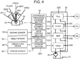
- FIG. 4 is a control block diagram of the dump truck 1.
- the dump truck 1 is provided with a controller (control device) 32, an operating lever device 28, a pilot pressure generation device 33, a grease feed device (lubricant supplier) 36, a seating sensor (seating detection device) 30, an angle sensor 59, and a stroke sensor 69.
- the controller 32 is connected on the input side with detection devices such as a lever sensor 29, the seating sensor 30, the angle sensor 59, the stroke sensor 69 and the like and is connected on the output side with the pilot pressure generation device 33, the grease feed device 36 and the like.
- the controller 32 is configured to include an arithmetic processing device having a CPU, a storage section 32A such as a ROM, a RAM and the like, and other peripheral circuits and executes the control of the overall system of the dump truck 1.
- the operating lever device 28 is operator means for operating the vessel 3 and is composed of, for example, an electric lever device.
- the operating lever device 28 has an operating lever 28A and the lever sensor 29 that detects the operating position of the operating lever 28A.
- the operating lever 28A is an operation member that the operator in the cab 6 pivotally operates by hand.
- the operating lever 28A can take a hold position 28A1 indicated by the solid line in FIG. 4 and a floating position 28A2 indicated by the two-dot-chain line and usually takes the hold position 28A1.
- the hold position 28A1 is an operation position that makes the vessel 3 to be stopped and held at a desired position.
- the operating lever 28A is automatically returned by a first return spring (not shown) to the hold position 28A1.
- the operating lever 28A When the operator operates the operating lever 28A from the hold position 28A1 to the floating position 28A2, the operating lever 28A is self-held at the floating position 28A2 by a well-known detent mechanism (not shown). When the operator releases the operating lever 28A from his/her hand in the state that the operating lever 28A is pivotally operated from the floating position 28A2 in the arrow L direction, the operating lever 28A is automatically returned by a second return spring (not shown) to the floating position 28A2.
- the lever sensor 29 detects the operation position of the operating lever 28A pivotally operated by the operator and outputs its detection signal to the controller 32.
- the controller 32 determines the switching position of the valve 16 in dependence on the operation position of the operating lever 28A and outputs a control signal corresponding to the switching position to the pilot pressure generation device 33.
- the pilot pressure generation device 33 is, for example, an electric-hydraulic conversion device constituted by an electromagnetic proportional valve and converts control signals (electric signals) from the controller 32 into the pilot pressures (hydraulic signals) Pb, Pc and Pd.
- the pilot pressure generation device 33 is provided with four operation sections comprising a hold operation section 33A, a rise operation section 33B, a floating operation section 33C, and a fall operation section 33D.
- the pilot pump 34 is rotationally driven by the engine 9 to supply the pilot pressure generation device 33 with pressurized oil of the degree ranging, for example, from 0.5 to 5.0 MPa (Mega-pascal).
- the pilot pressure generation device 33 outputs the pressurized oil from the pilot pump 34 as the pilot pressures Pb, Pc and Pd to the valve 16 (refer to FIG. 3 ).
- the controller 32 outputs a control signal to any one only at a time of the hold operation section 33A, the rise operation section 33B, the floating operation section 33C and the fall operation section 33D, during which the controller 32 does not output the control signal to any other operation section.
- the controller 32 When the operating lever 28A is placed at the hold position 28A1, the controller 32 outputs the control signal to the hold operation section 33A of the pilot pressure generation device 33.
- the pilot pressure generation device 33 does not output any of the pilot pressures Pb, Pc and Pd while the control signal is inputted to the hold operation section 33A.
- the valve 16 shown in FIG. 3 turns to "hold position" with the first directional control valve 20 and the second directional control valve 21 each taking the hold position assigned to the neutral position (a).
- the switching of the valve 16 to the hold position stops the supply of the hydraulic oil from the main pump 11 to the hoist cylinder 10 and the discharge of hydraulic oil from the hoist cylinder 10 to the hydraulic oil reservoir 12. That is, with the valve 16 switched to "hold position", the hoist cylinder 10 is stopped from movement to be held, whereby the vessel 3 is stopped and held at the present position.
- the controller 32 when the operating lever 28A is operated from the hold position 28A1 to the rise side (in the arrow R direction), the controller 32 outputs the control signal to the rise operation section 33B of the pilot pressure generation device 33.
- the rise operation section 33B when given the control signal inputted from the controller 32, outputs the pilot pressure Pb to the hydraulic pilot portion 20A of the first directional control valve 20 and the hydraulic pilot portion 21A of the second directional control valve 21 which are shown in FIG. 3 .
- a pressure close to the reservoir pressure acts as the pilot pressure on the hydraulic pilot portion 20B of the first directional control valve 20 and the hydraulic pilot portion 21B of the second directional control valve 21.
- valve 16 turns to "rise position" with the first directional control valve 20 and the second directional control valve 21 each switched from the neutral position (a) to the rise position (b).
- the pressurized oil discharged from the main pump 11 is supplied to the oil chamber A of the hoist cylinder 10 through the pump pipe conduit 13, the high-pressure side oil passage 17, the second directional control valve 21, the actuator-side oil passage 23A and the hydraulic pipe conduit 15A.
- the hydraulic oil in the oil chamber B is discharged to the hydraulic oil reservoir 12 through the hydraulic pipe conduit 15B, the actuator-side oil passage 22B, the first directional control valve 20, the low-pressure side oil passage 18 and the reservoir pipe conduit 14.
- the valve 16 is switched to "rise position"
- the piston rod 10C of the hoist cylinder 10 continues to extend and lifts up the front part side of the vessel 3, and thus, the vessel 3 is pivotally moved toward the dumping position (refer to FIG. 2 ). That is, the vessel 3 rises up.
- the controller 32 when the operating lever 28A is operated from the hold position 28A1 to the floating position 28A2, the controller 32 outputs the control signal to the floating operation section 33C of the pilot pressure generation device 33. With the control signal inputted from the controller 32, the floating operation section 33C outputs the pilot pressure Pc to the hydraulic pilot portion 20B of the first directional control valve 20 shown in FIG. 3 . At this time, a pressure close to the reservoir pressure acts as the pilot pressure on the hydraulic pilot portion 20A of the first directional control valve 20 and the hydraulic pilot portions 21A, 21B of the second directional control valve 21.
- the valve 16 turns to "floating position" with the first directional control valve 20 switched from the neutral position (a) to the floating position (c) and with the second directional control valve 21 switched to the neutral position (a).
- the actuator-side oil passage 22A is connected to the the low-pressure side oil passage 18 and the reservoir pipe conduit 14 through the first directional control valve 20.
- the actuator-side oil passage 22B is connected to the the low-pressure side oil passage 18 and the reservoir pipe conduit 14 through the check valve 24B, and at the same time, the actuator-side oil passage 23B is connected to the low-pressure side oil passage 18 and the reservoir pipe conduit 14 through the check valve 26B.
- the hoist cylinder 10 contracts by virtue of the load (dead weight) of the vessel 3, and this causes the hydraulic oil in the oil chamber A to be discharged to the hydraulic oil reservoir 12 through the hydraulic pipe conduit 15A, the actuator-side oil passage 22A, the first directional control valve 20, the low-pressure side oil passage 18 and the reservoir pipe conduit 14. Further, the oil chamber B is replenished with the hydraulic oil in the hydraulic oil reservoir 12 from the check valves 24B, 26B through the actuator-side oil passages 22B, 23B and the hydraulic pipe conduit 15B. In short, with the valve 16 switched to "floating position", the vessel 3 is allowed to fall by virtue of its dead weight. Therefore, the vessel 3 pivotally moves (is tilted) downward to lower the front part side, so that the vessel 3 is seated on the vehicle frame 2 (refer to FIG. 1 ).
- the controller 32 when the operating lever 28A is operated from the floating position 28A2 toward the fall side (in the arrow L direction), the controller 32 outputs the control signal to the fall operation section 33D of the pilot pressure generation device 33.
- the fall operation section 33D When given the control signal inputted from the controller 32, the fall operation section 33D outputs the pilot pressure Pd to the hydraulic pilot portion 21B of the second directional control valve 21 shown in FIG. 3 .
- a pressure close to the reservoir pressure acts as the pilot pressure on the hydraulic pilot portion 21A of the second directional control valve 21 and the hydraulic pilot portions 20A, 20B of the first directional control valve 20.
- the valve 16 turns to "fall position" with the first directional control valve 20 switched to the neutral position (a) and with the second directional control valve 21 switched from the neutral position (a) to the fall position (d).
- the hydraulic oil from the main pump 11 is supplied to the oil chamber B of the hoist cylinder 10 through the pump pipe conduit 13, the high-pressure side oil passage 17, the second directional control valve 21, the actuator-side oil passage 23B and the hydraulic pipe conduit 15B.
- the hydraulic oil in the oil chamber A is discharged to the hydraulic oil reservoir 12 through the hydraulic pipe conduit 15A, the actuator-side oil passage 23A, the second directional control valve 21, the low-pressure side oil passage 18 and the reservoir pipe conduit 14.
- the hoist cylinder 10 causes the cylindrical inner tube portion 10B to contract together with the piston rod 10C into the cylindrical outer tube portion 10A due to the pressurized oil supplied in the oil chamber B.
- the hoist cylinder 10 causes the vessel 3 to pivotally move (tilt) downward to lower the front part side of the vessel 3 by the hydraulic power, whereby the vessel 3 is seated on the vehicle frame 2 (refer to FIG. 1 ).
- the angle sensor 59 is provided at the connection portion of the vessel 3 with the vehicle frame 2 and detects the pivotal angle of the vessel 3 that pivotally moves about the connecting pin 5 serving as the pivotal fulcrum, to output a detection signal to the controller 32.
- the pivotal angle ⁇ is set to become ⁇ min when the vessel 3 is in the seated state of being at the transportation position, become larger in its value as the vessel 3 is pivotally moved toward the dumping position, and become ⁇ max when the vessel 3 is positioned to the dumping position.
- the stroke sensor 69 detects the stroke position S of the hoist cylinder 10 and outputs a detection signal to the controller 32.
- the stroke position S is set so that, for example, the value becomes Smin with the hoist cylinder 10 made to contract most, becomes larger with the extension of the hoist cylinder 10 and becomes Smax in the state that the hoist cylinder 10 extends to its extreme end.
- the seating sensor 30 detects whether the vessel 3 is seated on the vehicle frame 2 or not, and outputs a detection signal to the controller 32. As shown in FIG. 1 and FIG. 2 , the seating sensor 30 is disposed on an upper part of the hydraulic oil reservoir 12.
- FIG. 5 is a side view showing the configuration of the seating sensor 30. As shown in FIG. 5 , the seating sensor 30 is a touch-type sensor installed on the vehicle frame 2 side and is provided with a rod-like touch terminal 30B. At the bottom part 3c of the vessel 3, a protruding portion 30A is provided that is arranged to brought into contact with the touch terminal 30B when the vessel 3 is seated on the vehicle frame 2.
- the seating sensor 30 When the protruding portion 30A being a target to be detected is in contact with the touch terminal 30B, the seating sensor 30 outputs an ON-signal to the controller 32. When the protruding portion 30A is separated from the touch terminal 30B not to effect the contact between the both members, the the seating sensor 30 outputs an OFF-signal to the controller 32.
- outputting the OFF-signal means that the ON-signal (control current) is not outputted to the controller 32, and this encompasses outputting a control current differing from the ON-signal and not outputting the control current.
- FIG. 6 is a circuit diagram showing the configuration of the grease feed device 36.
- the grease feed device 36 is provided with a grease feed control valve 360, a grease feed motor 361, a grease feed pump 362 and a grease feed reservoir 369 storing lubricant (lubrication oil) such as grease.
- the grease feed control valve 360 is an electromagnetic changeover valve that is switched between a closed position (g) and an open position (h) in response to a control signal (exciting current to a solenoid) outputted from the controller 32.
- a control signal exciting current to a solenoid
- the grease feed control valve 360 excites the solenoid to be switched to the open position (h).
- an OFF-signal is outputted from the controller 32, the grease feed control valve 360 demagnetizes the solenoid to be switched by a spring force to the closed position (g).
- the grease feed motor 361 is a hydraulic motor for lubricant supply that is driven by the pressurized oil discharged from the main pump 11.
- the grease feed motor 361 is coupled at its rotational shaft to a rotational shaft of the grease feed pump 362.
- the grease feed pump 362 discharges lubricant stored in the grease feed reservoir 369 when rotationally driven by the grease feed motor 361.
- a discharge side of the grease feed pump 362 is connected through a grease feed hose 35 to a grease feed hole 111 in the rod head 101 of the hoist cylinder 10.
- the grease feed motor 361 When the grease feed control valve 360 is switched to the open position (h), the grease feed motor 361 is driven by the pressurized oil discharged from the main pump 11. The driving of the grease feed motor 361 effects the driving of the grease feed pump 362, whereby lubricant discharged from the grease feed pump 362 is supplied to the rod head 101 of the hoist cylinder 10 through the grease feed hose 35.
- the grease feed control valve 360 is switched to the closed position (g)
- the rotation of the grease feed pump 362 is stopped, whereby the supply of the lubricant to the rod head 101 is discontinued.
- FIG. 7A is a schematic longitudinal-sectional view of the connection portion between the hoist cylinder 10 and the hoist shaft 133, taken along an imaginary plane parallel to the center axis CL of the hoist shaft 133.
- FIG. 7B is a fragmentary enlarged view of a portion C in FIG. 7A .
- the rod head 101 of the hoist cylinder 10 is provided with the bore 102 into which the cylindrical bushing 134 is press-fitted.
- the bushing 134 is provided with the cylindrical through bore 134h that enables the hoist shaft 133 to pass through.
- the hoist shaft 133 is inserted into the through bore 134h of the bushing 134, which connects the hoist cylinder 10 with the vehicle frame 2. Sliding is enabled between the internal surface of the bushing 134 and the surface of the hoist shaft 133, so that the hoist cylinder 10 is pivotable about the hoist shaft 133 serving as the pivotal fulcrum.
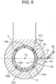
- FIG. 8 and FIG. 9 are each a fragmentary cross-sectional view of the connection portion between the hoist cylinder 10 and the hoist shaft 133, taken along an imaginary plane (A-A plane in FIG. 7A ) perpendicular to the center axis CL of the hoist shaft 133.
- A-A plane in FIG. 7A an imaginary plane perpendicular to the center axis CL of the hoist shaft 133.
- FIG. 8 shows the positional relation between the bushing 134 and the hoist shaft 133 in the state that the vessel 3 is seated on the vehicle frame 2 and that the valve 16 is placed at the floating position.
- FIG. 9 shows the positional relation between the bushing 134 and the hoist shaft 133 in the state that the hoist cylinder 10 is made to contract by a predetermined amount from the state shown in FIG. 8 .
- the hoist cylinder 10 is provided with the grease feed hole 111 being a through hole for grease feed.
- the grease feed hole 111 is connected to the grease feed hose 35.
- the grease feed hose 35 is connected at one end to the grease feed hole 111 and at the other end to the discharge side of the grease feed pump 362 of the grease feed device 36 (refer to FIG. 6 ).
- a groove (hereafter noted as an outer circumferential groove 134a) that leads lubricant supplied from the grease feed device 36 is provided on the surface of the bushing 134 in the circumferential direction.
- a plurality (four in the example shown in FIG. 8 and FIG. 9 ) of communication holes 134t that make a gap in the outer circumferential groove 134a communicate with a clearance between the surface of the hoist shaft 133 and the internal surface of the through bore 134h of the bushing 134 are provided in the outer circumferential groove 134a at equiangular intervals.
- a groove (hereafter noted as an inner circumferential groove 134b) that leads the lubricant introduced from the outer circumferential groove 134a through the plurality of the communication holes 134t to the whole circumference between the surface of the hoist shaft 133 and the internal surface of the through bore 134h of the bushing 134.
- the valve 16 is switched to the floating position to let the vessel 3 to be seated on the vehicle frame 2 by virtue of the dead weight. Further, it is also conventional that also during the traveling of the vehicle, the valve 16 is held to remain at the floating position to keep the contraction state of the hoist cylinder 10 by making use of the dead weight of the hoist cylinder 10. As shown in FIG. 1 , where the valve 16 has been switched to the floating position with the vessel 3 seated on the vehicle frame 2, the dead weight of the hoist cylinder 10 is supported by the hoist shaft 133, as shown in FIG. 8 . Thus, a surface upper part ⁇ of the hoist shaft 133 comes to close contact with the internal surface upper part of the through bore 134h of the bushing 134.
- the hoist shaft 133 and the bushing 134 are in close contact at the upper parts thereof during the dumping work and the traveling as shown in FIG. 8 . Accordingly, even when lubricant is supplied between the hoist shaft 133 and the bushing 134, it is unable for the lubricant to permeate satisfactorily into the close-contact portion at the upper parts. As a result, the progress of abrasion of the bushing 134 at the upper close-contact portion becomes faster than other portions (for example, the internal surface lower part of the bushing 134).
- the hoist cylinder 10 is made to contract slightly with the vessel 3 seated on the vehicle frame 2, and lubricant is supplied in the state that as shown in FIG. 9 , a clearance CS2 is formed between the surface upper part ⁇ of the hoist shaft 133 and the internal surface upper part of the through bore 134h of the bushing 134.
- a lubricant supply control i.e., the contract control of the hoist cylinder 10 and the driving control of the grease feed device 36
- the controller 32 executes the lubricant supply control in accordance with a lubricant supply control program stored in the storage section 32A.
- the controller 32 is provided as functions thereof with an operation judgment section 320, a seating judgment section 321, a valve control section (lubricant supply control section) 322 and a grease feed control section (lubricant supply control section) 323.
- the operation judgment section 320 judges based on information on the pivotal angle of the vessel 3 detected by the angle sensor 59 whether or not, the vessel 3 is pivoting from the dumping position side in the direction toward the transportation position, that is, whether or not, the vessel 3 is being operated to fall.
- the operation judgment section 320 judges that the fall operation of the vessel 3 is being performed.
- that the fall operation of the vessel 3 is being performed means the operation being in a non-seated state that the vessel 3 is not seated on the vehicle frame 2, and thus, the judgment whether the vessel 3 is being operated to fall or not corresponds to making a judgment whether to be in the non-seated state or not.
- the seating judgment section 321 judges based on the signal from the seating sensor 30 whether the vessels 3 is seated or not. When given the ON-signal inputted from the seating sensor 30, the seating judgment section 321 judges that the vessel 3 is seated, that is, the vessel 3 is at the transportation position. When given the OFF-signal outputted from the seating sensor 30, the seating judgment section 321 judges that the vessel 3 is not seated, that is, the vessel 3 is not at the transportation position.
- the valve control section 322 When the vessel 3 is judged to be seated, the valve control section 322 outputs a control signal to the fall operation section 33D of the pilot pressure generation device 33 to switch the second directional control valve 21 of the valve 16 to the fall position (d), and this causes the hoist cylinder 10 to contract until the stroke position S of the hoist cylinder 10 becomes a threshold value S0.
- the valve control section 322 When the stroke position S detected by the stroke sensor 69 becomes equal to or less than the threshold value S0, the valve control section 322 outputs a control signal to the hold operation section 33A of the pilot pressure generation device 33 to switch the first directional control valve 20 and the second directional control valve 21 of the valve 16 to the neutral position (a), whereby the hoist cylinder 10 discontinues the operation to keep the contraction state.
- the threshold value S0 designates the stroke position S that the hoist cylinder 10 has when the vessel 3 is seated on the vehicle frame 2 and when as shown in FIG. 9 , the surface lower part ⁇ of the hoist shaft 133 contacts the internal surface lower part of the bushing 134 of the rod head 101, and is stored beforehand in the storage section 32A of the controller 32 (Smin ⁇ S0 ⁇ Smax).
- the grease feed control section 323 When the vessel 3 is judged to be seated, the grease feed control section 323 outputs the ON-signal to the grease feed control valve 360 of the grease feed device 36 to switch the grease feed control valve 360 to the open position (h) and drives the grease feed device 36 until the driving period of time (i.e., greasing period of time) of the grease feed device 36 becomes a time threshold value t0 or longer.
- the time threshold value t0 is stored beforehand in the storage section 32A of the controller 32.
- the grease feed control section 323 judges whether the state that the grease feed pump 362 is supplying lubricant to the hoist cylinder 10 has been continued for the period of the time threshold value t0 or longer.
- the grease feed control section 323 judges that a grease feed end condition is satisfied, and outputs the OFF-signal to the grease feed control valve 360, whereby the grease feed control valve 360 is switched to the closed position (g) to stop the grease feed device 36.
- valve control section 322 After the supply of lubricant by the grease feed device 36 is discontinued upon satisfaction of the grease feed end condition, the valve control section 322 outputs the control signal to the floating operation section 33C of the pilot pressure generation device 33 to switch the first directional control valve 20 of the valve 16 to the floating position (c).
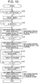
- FIG. 10 is a flowchart showing the processing details of the lubricant supply control by the controller 32 according to the present embodiment.
- the processing shown in this flowchart is started for example by turning a starter switch (i.e., ignition switch, not shown) to ON and is repetitively executed in a predetermined control cycle after the execution of an initial setting (not shown).
- a starter switch i.e., ignition switch, not shown
- the controller 32 is designed to acquire information from various sensors such as the seating sensor 30, the angle sensor 59, the lever sensor 29, the stroke sensor 69 and the like on a predetermined control cycle.
- step S110 the controller 32 judges based on the signal from the angle sensor 59 whether the vessel 3 is being operated to fall or not. The step S110 is repeated until an affirmative judgment is made, and the processing proceeds to step S120 when the affirmative judgment is made.
- step 120 the controller 32 sets to 0 (zero) a grease feed period of time t that is counted by a timer built in the controller 32, that is, initializes the grease feed period of time t (i.e., resets the timer) and then, advances the processing to step 130.
- step S130 the controller 32 judges based on the signal from the seating sensor 30 whether the vessel 3 is seated on the vehicle frame 2 or not. The step S130 is repeated until an affirmative judgment is made, and the processing proceeds to step S140 when the affirmative judgment is made.
- the controller 32 judges that the vessel 3 has turned from the non-seated state in which the vessel 3 is not seated on the vehicle frame 2 to the seated state in which it is seated, and then executes the lubricant supply control (steps S140 through S170).
- step S140 the controller 32 outputs a control signal to the fall operation section 33D (refer to FIG. 4 ) of the pilot pressure generation device 33 and proceeds to step S143.
- the pilot pressure Pd is outputted from the pilot pressure generation device 33 to the hydraulic pilot portion 21B of the second directional control valve 21 of the valve 16, and thus, the second directional control valve 21 is switched to the fall position (d) (refer to FIG. 3 ).
- a pressure close to the reservoir pressure acts on the hydraulic pilot portions 20A, 20B of the first directional control valve 20, and thus, the first directional control valve 20 is held switched to the neutral position (a).
- step S143 the controller 32 judges whether the stroke position S is equal to or less than the threshold value S0 or not. An affirmative judgment at step S143 results in going to step S147, while a negative judgment at step S143 results in returning to step S140.
- step S147 the controller 32 outputs a control signal to the hold operation section 33A (refer to FIG. 4 ) of the pilot pressure generation device 33 and proceeds to step S150.
- the pressure acting on the hydraulic pilot portions 21A, 21B of the second directional control valve 21 goes down to a pressure close to the reservoir pressure, so that the second directional control valve 21 is switched to the neutral position (a) (refer to FIG. 3 ).
- step S150 the controller 32 outputs the ON-signal to the grease feed control valve 360 to switch the same to the open position (h) (refer to FIG. 6 ) and then proceeds to step S153.
- step S157 the controller 32 judges whether the grease feed period of time t has become equal to or longer than the time threshold value t0 or not. An affirmative judgment at step S157 results in going to step S160, while a negative judgment at step S157 results in returning to step S150.
- step S160 the controller 32 outputs the OFF-signal to the grease feed control valve 360 (i.e., discontinues the outputting of the ON-signal (i.e., exciting current)) to switch the grease feed control valve 360 to the closed position (g) (refer to FIG. 6 ) and then proceeds to step S170.
- the controller 32 outputs the OFF-signal to the grease feed control valve 360 (i.e., discontinues the outputting of the ON-signal (i.e., exciting current)) to switch the grease feed control valve 360 to the closed position (g) (refer to FIG. 6 ) and then proceeds to step S170.
- the controller 32 outputs a control signal to the floating operation section 33C (refer to FIG. 4 ) of the pilot pressure generation device 33 and terminates the processing shown as the flowchart in FIG. 10 .
- the pilot pressure Pc is outputted from the pilot pressure generation device 33 to the hydraulic pilot portion 20B of the first directional control valve 20 of the valve 16, whereby the first directional control valve 20 is switched to the floating position (c) (refer to FIG. 3 ).
- the vessel 3 falls by virtue of its dead (empty) weight about the connecting pin 5 acting as the pivotal fulcrum, and when the vessel 3 is moved from the non-seated state in which the protruding portion 30A provided as a target for detection on the vessel 3 side is spaced from the seating sensor 30, to the seated state in which the protruding portion 30A is in contact with the touch terminal 30B (refer to FIG. 5 ) of the seating sensor 30, the lubricant supply control is executed by the controller 32. In the lubricant supply control, a switching control is executed to switch the switching position of the pilot pressure generation device 33 to the fall position (from Yes at step S110 through Yes at step S130 to step S140).
- the hoist cylinder 10 contracts further than it does in the usual seated state with the valve 16 having been switched to the floating position.
- the contract operation of the hoist cylinder 10 is discontinued, and the same is held at the discontinued position (from Yes at step S143 to step S147).
- the surface lower part ⁇ of the hoist shaft 133 and the internal surface lower part of the through bore 134h of the bushing 134 contact each other at a predetermined contact pressure, so that the clearance CS2 is formed between the internal surface upper part of the through bore 134h of the bushing 134 and the surface upper part ⁇ of the hoist shaft 133.
- lubricant is supplied from the grease feed device 36 through the grease feed hose 35 to the grease supply hole 111 of the rod head 101 (from step S150 through step S153 to No at step S157).
- the lubricant supplied to the rod head 101 is filled up in the outer circumferential groove 134a of the bushing 134 shown in FIG. 7B and is supplied to the clearance CS2 through the communication holes 134t extending radially inward from the outer circumferential groove 134a.
- the lubricant supplied to the clearance CS2 permeates into the whole circumference of the hoist shaft 133 through the inner circumferential groove 134b. As a result, lubrication is given over the surface of the hoist shaft 133 and the internal surface of the through bore 134h of the bushing 134.
- the surface upper part ⁇ of the hoist shaft 133 contacts the internal surface upper part of the through bore 134h of the bushing 134 at a predetermined contact pressure, whereby the clearance CS1 is formed between the internal surface lower part of the through bore 134h of the bushing 134 and the surface lower part ⁇ of the hoist shaft 133.
- the present embodiment is applied to the dump truck 1 having the vessel 3 provided pivotably relative to the vehicle frame 2, the hoist cylinder 10 telescopically provided between the vessel 3 and the vehicle frame 2, the main pump 11 for supplying hydraulic oil to the hoist cylinder 10, and the valve 16 provided between the main pump 11 and the hoist cylinder 10 for controlling the flow of hydraulic oil supplied to the hoist cylinder 10.
- the angle sensor 59 that detects the pivotal angle ⁇ of the vessel 3 using the connecting pin 5 as the pivotal fulcrum may be used as the seating sensor 30.
- the controller 32 judges that the vessel 3 is seated on the vehicle frame 2 when the pivotal angle ⁇ of the vessel 3 detected by the angle sensor 59 becomes equal to or less than the angle threshold value ⁇ 0.
- the angle threshold value ⁇ 0 is determined as a pivotal angle which is made by adding a tolerance (e.g., one degree or so) to the angle ⁇ min that the vessel 3 has when seated, and is stored beforehand in the storage section 32A of the controller 32.
- the controller 32 may control the valve 16 to make the hoist cylinder 10 contract and may control the grease feed device 36 to supply lubricant to the clearance CS2 between the hoist shaft 133 and the bushing 134.
- the controller 32 may control the valve 16 to make the hoist cylinder 10 contract and may control the grease feed device 36 to supply lubricant to the clearance CS2 between the hoist shaft 133 and the bushing 134.
- a grease feed switch (not shown) may be provided in the cab 6, in which case the lubricant supply control may be executed when the grease feed switch is operated in the state that the vessel 3 is judged to be in the seated state with itself being seated on the vehicle frame 2.
- the threshold value S0 of the stroke position S is used as the stroke position S that the rod head 101 takes at a position where the surface lower part ⁇ of the hoist shaft 133 and the internal surface lower part of the bushing 134 in the rod head 101 contact each other.
- the threshold value S0 may be such a stroke position S that can provide a clearance at least between the surface upper part ⁇ of the hoist shaft 133 and the internal surface upper part of the bushing 134.
- a stroke position S at which the center axis CL of the hoist shaft 133 becomes concentric with the center axis of the bore 102 of the rod head 101 may be stored as the threshold value S0 in the storage section 32A.
- the storage section 32A beforehand stores as the threshold value S0 such a stroke position S that makes the height dimension of the upper clearance CS2 between the hoist shaft 133 and the bushing 134 longer than the height dimension of the lower clearance CS1.
- the operation judgment section 320 judges based on the detection signal from the angle sensor 59 whether the vessel 3 is being operated to fall or not.
- the operation judgment section 320 may judge based on the detection signal from the lever sensor 29 whether the operating lever 28A has been operated from the state of being operated to the operation position on the rise side or the hold position to the operation position on the fall side or to the floating position, and when an affirmative judgment is made, may judge that the vessel 3 is being operated to fall, that is, the vessel 3 is in the non-seated state.
- the controller 32 may judge based on the detection signal from the seating sensor 30 whether the vessel 3 is in the non-seated state or not. In the present modified form, when the vessel 3 is judged to be in the seated state following the judgment of the vessel 3 being in the non-seated state, the controller 32 may judge that the vessel 3 has proceeded from the non-seated state to the seated state.
- step S110 in FIG. 10 there may be added a floating position operation judgment step of judging whether the operating lever 28A is being operated to the floating position 28A2 or not.
- This floating position operation judgment step is repeated until an affirmative judgment is made, and when the operating lever 28A is judged to have been operated to the floating position 28A2 (in the case of the affirmative judgment), the processing proceeds to step S110.
- the present invention is not limited to the dump truck 1.
- the present invention is also applicable to a haulage vehicle such as a crawler carrier which mounts a vessel on a vehicle provided with a crawler-type traveling mechanism.
Landscapes
- Engineering & Computer Science (AREA)
- Mechanical Engineering (AREA)
- Transportation (AREA)
- Fluid-Pressure Circuits (AREA)
- Vehicle Cleaning, Maintenance, Repair, Refitting, And Outriggers (AREA)
- Forklifts And Lifting Vehicles (AREA)
Abstract
Description
- The present invention relates to a haulage vehicle.
- There has been known a dump truck with a vessel provided to be able to rise and fall on a vehicle. The dump truck transports a large amount of transportation objects such as crushed rocks, earth, sand and so on loaded in the vessel. The dump truck is provided with a hoist cylinder that is telescopically provided between the vessel and the vehicle and that extends to tilt the vessel when discharging the transportation objects from the vessel, as described in International Application Publication No.
WO2008/099691 . - The hoist cylinder is connected at its lower end with a hoist shaft provided in the vehicle and is connected at its upper end with the vessel by means of a pin. The hoist cylinder has a rod head disposed at its lower end, the rod head is provided with a bore through which the hoist shaft passes, and a cylindrical bushing is arranged in the bore.
- The hoist shaft is mounted on the rod head through the cylindrical bushing. The inside diameter of the bushing provided on the rod head is set to be smaller slightly than the outside diameter of the hoist shaft.
- The hoist shaft supports the dead weight of those including the vessel and the hoist cylinder. That is, the hoist shaft supports the load directed downward (toward the ground under the vehicle). In this state, a tight contact is held between an internal surface upper part of the bushing and a surface upper part of the hoist shaft, and this gives rise to a problem that it is unable to supply lubricant to the tight contact portion between the hoist shaft and the bushing and hence, that the upper parts of the hoist shaft and the bushing abrade easier than other parts thereof.
- In one aspect of the present invention, there is provided with a haulage vehicle, which is provided with: a vessel pivotably provided relative to a vehicle; a hoist cylinder provided telescopically between the vessel and the vehicle; a hydraulic power source that supplies the host cylinder with hydraulic oil; and a valve provided between the hydraulic power source and the hoist cylinder for controlling the flow of hydraulic oil supplied to the hoist cylinder, wherein the haulage vehicle is further provided with: a bushing provided at one end portion of the hoist cylinder; a hoist shaft provided in the vehicle and mounted in a through bore of the bushing; a lubricant supplier that supplies lubricant to a clearance between a surface of the hoist shaft and an internal surface of the through bore of the bushing; a seating detection device that detects whether the vessel is seated on the vehicle or not; and/or a controller that when the vessel is seated on the vehicle, controls the valve to make the hoist cylinder contract and also controls the lubricant supplier to supply lubricant to the clearance.
- According to the present invention, it is possible to restrain the hoist shaft and the bushing of the hoist cylinder from abrading, so that the hoist shaft and the bushing can be extended in service life.
- A non-limiting and non-exhaustive embodiment of the present invention will be described with reference to the following drawings, wherein like reference signs refer to like parts throughout various views unless otherwise specified.
-
FIG. 1 is a side view of a dump truck according to one embodiment of the present invention, -
FIG. 2 is a side view of the dump truck with a vessel tilted obliquely rearward, -
FIG. 3 is a hydraulic circuit diagram for driving a hoist cylinder, -
FIG. 4 is a control block diagram for the dump truck, -
FIG. 5 is a side view showing the configuration of a seating sensor, -
FIG. 6 is a circuit diagram showing a grease feed device, -
FIG. 7A is a schematic longitudinal-sectional view of a connection portion between the hoist cylinder and the hoist shaft, taken along an imaginary plane parallel to the axis of the hoist shaft, -
FIG. 7B is a fragmentary enlarged view of a portion C inFIG. 7A , -
FIG. 8 is a fragmentary cross-sectional view showing the positional relation between a bushing and the hoist shaft in the state that the vessel is seated on a vehicle and that a valve is operated in a float position, -
FIG. 9 is another fragmentary cross-sectional view showing the positional relation between the bushing and the hoist shaft in the state that the hoist cylinder is made to contract by a predetermined amount from the state shown inFIG. 8 , and -
FIG. 10 is a flowchart showing the processing details of a lubricant supply control by a controller according to the present embodiment. - Hereafter, with reference to the drawings, one embodiment of a haulage vehicle according to the present invention will be described by taking as example a heavy-duty dump truck that transports crushed rocks and the like mined in mines and the like.
FIG. 1 is a side view (as viewed from left side of the vehicle) of adump truck 1 according to one embodiment of the present invention.FIG. 2 is a side view (as viewed from left side of the vehicle) of thedump truck 1 with avessel 3 tilted obliquely rearward. For convenience in description, the front-rear direction and the upper-lower (upward-downward) direction are prescribed as indicated in these figures. - As shown in
FIG. 1 andFIG. 2 , thedump truck 1 is provided with a self-propellable vehicle, thevessel 3 as a loading platform that is provided to be able to rise and fall (i.e., to be pivotable) on avehicle frame 2 constituting the vehicle, a cab (driver's cab) 6 provided at the front part of thevehicle frame 2, and hoistcylinders 10 that pivotably move the vessel 3 (i.e., that make thevessel 3 rise or fall) in the upward-downward direction. - The
vessel 3 is formed as , for example, a giant-sized container of 10-13 meters long in entire length for loading thereon a large amount of heavy transportation objects such as crushed rocks and the like (hereafter referred to as crushed rocks 4). Thevessel 3 is integrally provided with acontainer section 3B for containing the crushedrocks 4 and acanopy section 3A which is provided at the front side of thecontainer section 3B and which covers the upper part of thecab 6 to protect thecab 6 from scattering rocks. - A bottom part on the rear side of the
vessel 3 is coupled with thevehicle frame 2 to be pivotable (to be able to rise and fall) relative to thevehicle frame 2 through a connectingpin 5 provided in the vicinity of the rear end of thevehicle frame 2. When thehoist cylinders 10 expand or contract, thevessel 3 rises or falls so that thecanopy section 3A on the front side of thevessel 3 pivots in the upward-downward about the connectingpin 5 serving as a fulcrum. Thevessel 3 is pivoted between a transportation position shown inFIG. 1 and a dumping position shown inFIG. 2 . When thehoist cylinders 10 expand to make thevessel 3 pivot toward the dumping position, the crushedrocks 4 loaded in thevessel 3 are discharged to a predetermined pickup/collection point as they slip down from thevessel 3 that is tilted obliquely rearward to have the rear side positioned below the front side as shown inFIG. 2 . When being at the transportation position as shown inFIG. 1 , thevessel 3 is held in the seated state with the bottom portion on the front side of thecontainer section 3B seated on a chassis table (not shown) of thevehicle frame 2. - In the
cab 6, there are provided a driver's seat on which an operator is seated, a starter switch for starting anengine 9, an acceleration pedal for causing the vehicle to travel, a brake pedal for giving the vehicle a brake force, a steering handle for steering operation (all not shown) and an operating lever device 28 (refer toFIG. 4 ) for making thevessel 3 to rise or fall. - The
dump truck 1 is provided withfront wheels 7 and rear wheels 8. Thefront wheels 7 constitute steered wheels which are steerable (can be given a steering operation) by the operator of thedump truck 1. Between the front part of thevehicle frame 2 and thefront wheels 7, there are provided frontwheel side suspensions 7A constituted by hydraulic shock absorbers, and the front part side of thevehicle frame 2 is supported by the frontwheel side suspensions 7A. - The rear wheels 8 constitute drive wheels of the
dump truck 1 and are rotationally driven by a traveling drive device (not shown). Between the rear wheels 8 and the rear part of thevehicle frame 2, there are provide rearwheel side suspensions 8A constituted by hydraulic shock absorbers and the like, so that the rear part side of thevehicle frame 2 is supported by the rearwheel side suspensions 8A. The outside diameter of thefront wheels 7 and the rear wheels 8 is up to the range of 2 to 4 meters. - Inside the
vehicle frame 2 under thecab 6, theengine 9 is provided as a prime mover. Theengine 9 is constituted by, for example, a large-sized diesel engine and the like. - Between the
vehicle frame 2 and thevessel 3, a pair of the hoist cylinders 10 (the hoist cylinder on the left side only is shown inFIG. 1 ) are provided telescopically. Eachhoist cylinder 10 is a hydraulic cylinder of a multistage type (e.g., a two-stage type). -
FIG. 3 shows a hydraulic circuit diagram for driving thehoist cylinders 10. Thehoist cylinders 10 are paired to have the same configuration. As shown inFIG. 3 , thehoist cylinders 10 are each provided with a cylindricalouter tube portion 10A, a cylindricalinner tube portion 10B provided telescopically inside theouter tube portion 10A and partitioning the interior of theouter tube portion 10A into an upper side oil chamber A and a lower side oil chamber B, and apiston rod 10C provided telescopically in the interior of theinner tube portion 10B. As mentioned, the pair of thehoist cylinders 10 are identical in its configuration and operation as well as in connection relation with the hydraulic circuit shown inFIG. 3 . Therefore, as a matter of convenience, the following description will be directed typically to one only of thehoist cylinders 10 unless otherwise specified to the contrary, and such description directed to onehoist cylinder 10 will be equally applied to theother hoist cylinder 10. - The
hoist cylinder 10 extends thepiston rod 10C when supplied at the oil chamber A with hydraulic oil from themain pump 11 and when discharging hydraulic oil from the oil chamber B, and makes thepiston rod 10C contract when supplied at the oil chamber B with hydraulic oil from themain pump 11 and when discharging hydraulic oil from the oil chamber A. When thehoist cylinder 10 extends, thevessel 3 is pivoted about the connectingpin 5 severing as a fulcrum toward the dumping position (refer toFIG. 2 ). When the hoistcylinder 10 contracts, thevessel 3 is pivoted about the connectingpin 5 severing as the fulcrum toward the transportation position (refer toFIG. 1 ). - The
vehicle frame 2 is provided with a hoistshaft 133 being a cylindrical member extending horizontally in the right-left direction (refer toFIG. 1 ). As shown inFIG. 3 , the hoistcylinder 10 is provided with a bore 102 (refer toFIG. 7A ) at an extreme end portion of the piston rod 10c (hereafter referred to as "rod head 101"), and acylindrical bushing 134 is press-fitted in thisbore 102. Thebushing 134 is provided with a throughbore 134h into which the hoistshaft 133 is inserted. Likewise, a bore is provided at an upper end part of theouter tube portion 10A of the hoistcylinder 10, and acylindrical bushing 154 is press-fitted in this bore. Thebushing 154 is provided with a throughbore 154h into which a vessel mounting pin (not shown) provided in a bracket (not shown) of thevessel 3 is inserted. - The hoist
shaft 133 is mounted with itself inserted into the throughbore 134h of thebushing 134 in therod head 101 of thepiston rod 10C. The vessel mounting pin (not shown) is mounted with itself inserted into the throughbore 154h of thebushing 154 on theouter tube portion 10A. Like this, the hoistcylinder 10 is pivotably mounted to thevessel 3 at its one end part and is pivotably mounted to thevehicle frame 2 at the other end part and is able to extend and contract between thevessel 3 and thevehicle frame 2. - The
engine 9 has an output shaft coupled with amain pump 11 and apilot pump 34. Themain pump 11 and thepilot pump 34 are rotationally driven by theengine 9, and are each a hydraulic pump that discharges hydraulic oil stored in ahydraulic oil reservoir 12. - The
main pump 11 and thehydraulic oil reservoir 12 configure a hydraulic power source that supplies hydraulic oil to the hoistcylinder 10. Thehydraulic oil reservoir 12 is located under thevessel 3 and is attached to a lateral surface of the vehicle frame 2 (refer toFIG. 1 andFIG. 2 ). - The hydraulic oil stored in the
hydraulic oil reservoir 12 is discharged as pressurized oil from a discharge side of themain pump 11 into a high-pressurepump pipe conduit 13 when themain pump 11 is rotationally driven by theengine 9. Further, the return oil from the hoistcylinder 10 is discharged to thehydraulic oil reservoir 12 through a low-pressurereservoir pipe conduit 14. - The hoist
cylinder 10 is connected with ahydraulic pipe conduit 15A at the oil chamber A and with ahydraulic pipe conduit 15B at the oil chamber B. Thehydraulic pipe conduits main pump 11 and thehydraulic oil reservoir 12 constituting the hydraulic power source through thevalve 16. - The
valve 16 is provided between the hydraulic power source (i.e., themain pump 11 and the hydraulic oil reservoir 12) and the hoistcylinder 10. Thevalve 16, when switched in response to a pilot pressure from a pilot pressure generation device 33 (refer toFIG. 4 ) described later, controls the flow of the hydraulic oil supplied from themain pump 11 to the hoistcylinder 10 and the flow of the hydraulic oil discharged from the hoistcylinder 10 to thehydraulic oil reservoir 12. Thevalve 16 is provided with a high-pressureside oil passage 17, a low-pressureside oil passage 18, abypass oil passage 19, a firstdirectional control valve 20, and a seconddirectional control valve 21. The firstdirectional control valve 20 and the seconddirectional control valve 21 are connected in parallel to each other through the high-pressureside oil passage 17 and the low-pressureside oil passage 18 and further, are in a tandem connection through thebypass oil passage 19. - The high-pressure
side oil passage 17 is connected to the discharge side of themain pump 11 through thepump pipe conduit 13, while the low-pressureside oil passage 18 is connected to thehydraulic oil reservoir 12 through thereservoir pipe conduit 14. When the firstdirectional control valve 20 and the seconddirectional control valve 21 are both at a neutral position (a), thebypass oil passage 19 makes the high-pressureside oil passage 17 communicate with the low-pressureside oil passage 18 to bring themain pump 11 into an unloaded state, so that the discharge pressure (the pressure in the pump pipe conduit 13) is kept in a low-pressure state being close to the reservoir pressure. - The first
directional control valve 20 is provided on the output side with a pair of actuator-side oil passages side oil passages cylinder 10 through thehydraulic pipe conduits directional control valve 21 is provided on the output side with a pair of actuator-side oil passages side oil passages cylinder 10 through thehydraulic pipe conduits - The first
directional control valve 20 and the seconddirectional control valve 21 are each a hydraulically piloted 6-port 3-position directional control valve. The firstdirectional control valve 20 is provided with a pair ofhydraulic pilot portions directional control valve 20 is switched from the neutral position (a) to a rise position (b) when supplied with a pilot pressure Pb at thehydraulic pilot portion 20A and is switched from the neutral position (a) to a floating position (c) when supplied with a pilot pressure Pc at thehydraulic pilot portion 20B. The seconddirectional control valve 21 is provided with a pair ofhydraulic pilot portions directional control valve 21 is switched from the neutral position (a) to a rise position (b) when supplied with the pilot pressure Pb at thehydraulic pilot portion 21A and is switched from the neutral position (a) to a fall position (d) when supplied with a pilot pressure Pd at thehydraulic pilot portion 21B. Description will later be made regarding the configuration of a pilotpressure generation device 33 that generates the pilot pressures Pb, Pc and Pd for switching the firstdirectional control valve 20 and the seconddirectional control valve 21. - As shown in
FIG. 3 , thevalve 16 is provided withcheck valves directional control valve 20 side. Thecheck valves side oil passages side oil passage 18 to detour the firstdirectional control valve 20. Thecheck valves hydraulic oil reservoir 12 to flow from the low-pressureside oil passage 18 through the actuator-side oil passages hydraulic pipe conduits cylinder 10, but prevent the flow in the opposite direction. Thus, the oil chambers A, B of the hoistcylinder 10 are replenished with hydraulic oil and are prevented from becoming a negative pressure. - The
valve 16 is provided withrelief valves relief valves side oil passages side oil passage 18 to detour the firstdirectional control valve 20. Therelief valves check valves relief valve 25A opens when an overload in the contract direction acts on the hoistcylinder 10, to release the excess pressure on the oil chamber A side. Therelief valve 25B opens when an overload in the extension direction acts on the hoistcylinder 10, to release the excess pressure on the oil chamber B side. - The
valve 16 is provided withcheck valves directional control valve 21 side. Thecheck valves side oil passages side oil passage 18 to detour the seconddirectional control valve 21. Thecheck valves hydraulic oil reservoir 12 to flow from the low-pressureside oil passage 18 through the actuator-side oil passages hydraulic pipe conduits cylinder 10, but prevent the flow in the opposite direction. Thus, the oil chambers A, B of the hoistcylinder 10 are replenished with hydraulic oil and are prevented from becoming a negative pressure. - The
valve 16 is provided with arelief valve 27 arranged between the high-pressureside oil passage 17 and the low-pressureside oil passage 18. Therelief valve 27 is a relief valve which is variable in relief set pressure and prescribes the maximum discharge pressure of themain pump 11. When a pressure exceeding the maximum discharge pressure is generated, therelief valve 27 releases the excess pressure to thehydraulic oil reservoir 12. - The
relief valve 27 has a variable pressure setting portion 27A supplied with the pilot pressure Pb. When the pilot pressure Pb acts on the variable pressure setting portion 27A, the relief set pressure is switched to a high-pressure setting. On the contrary, when the supply of the pilot pressure Pb is stopped, the relief set pressure of therelief valve 27 is switched to a low-pressure setting. -
FIG. 4 is a control block diagram of thedump truck 1. As shown inFIG. 4 , thedump truck 1 is provided with a controller (control device) 32, an operatinglever device 28, a pilotpressure generation device 33, a grease feed device (lubricant supplier) 36, a seating sensor (seating detection device) 30, anangle sensor 59, and astroke sensor 69. - The
controller 32 is connected on the input side with detection devices such as alever sensor 29, theseating sensor 30, theangle sensor 59, thestroke sensor 69 and the like and is connected on the output side with the pilotpressure generation device 33, thegrease feed device 36 and the like. Thecontroller 32 is configured to include an arithmetic processing device having a CPU, astorage section 32A such as a ROM, a RAM and the like, and other peripheral circuits and executes the control of the overall system of thedump truck 1. - The operating
lever device 28 is operator means for operating thevessel 3 and is composed of, for example, an electric lever device. The operatinglever device 28 has an operatinglever 28A and thelever sensor 29 that detects the operating position of the operatinglever 28A. The operatinglever 28A is an operation member that the operator in thecab 6 pivotally operates by hand. - The operating
lever 28A can take a hold position 28A1 indicated by the solid line inFIG. 4 and a floating position 28A2 indicated by the two-dot-chain line and usually takes the hold position 28A1. The hold position 28A1 is an operation position that makes thevessel 3 to be stopped and held at a desired position. When the operator releases the operatinglever 28A from his/her hand in the state that the operatinglever 28A is pivotally operated from the hold position 28A1 in the arrow R direction, the operatinglever 28A is automatically returned by a first return spring (not shown) to the hold position 28A1. When the operator operates the operatinglever 28A from the hold position 28A1 to the floating position 28A2, the operatinglever 28A is self-held at the floating position 28A2 by a well-known detent mechanism (not shown). When the operator releases the operatinglever 28A from his/her hand in the state that the operatinglever 28A is pivotally operated from the floating position 28A2 in the arrow L direction, the operatinglever 28A is automatically returned by a second return spring (not shown) to the floating position 28A2. - The
lever sensor 29 detects the operation position of the operatinglever 28A pivotally operated by the operator and outputs its detection signal to thecontroller 32. Thecontroller 32 determines the switching position of thevalve 16 in dependence on the operation position of the operatinglever 28A and outputs a control signal corresponding to the switching position to the pilotpressure generation device 33. - The pilot
pressure generation device 33 is, for example, an electric-hydraulic conversion device constituted by an electromagnetic proportional valve and converts control signals (electric signals) from thecontroller 32 into the pilot pressures (hydraulic signals) Pb, Pc and Pd. The pilotpressure generation device 33 is provided with four operation sections comprising ahold operation section 33A, arise operation section 33B, a floatingoperation section 33C, and afall operation section 33D. - The
pilot pump 34 is rotationally driven by theengine 9 to supply the pilotpressure generation device 33 with pressurized oil of the degree ranging, for example, from 0.5 to 5.0 MPa (Mega-pascal). On the basis of the operation position of the operatinglever 28A, the pilotpressure generation device 33 outputs the pressurized oil from thepilot pump 34 as the pilot pressures Pb, Pc and Pd to the valve 16 (refer toFIG. 3 ). - The
controller 32 outputs a control signal to any one only at a time of thehold operation section 33A, therise operation section 33B, the floatingoperation section 33C and thefall operation section 33D, during which thecontroller 32 does not output the control signal to any other operation section. - When the operating
lever 28A is placed at the hold position 28A1, thecontroller 32 outputs the control signal to thehold operation section 33A of the pilotpressure generation device 33. The pilotpressure generation device 33 does not output any of the pilot pressures Pb, Pc and Pd while the control signal is inputted to thehold operation section 33A. - Thus, the
valve 16 shown inFIG. 3 turns to "hold position" with the firstdirectional control valve 20 and the seconddirectional control valve 21 each taking the hold position assigned to the neutral position (a). The switching of thevalve 16 to the hold position stops the supply of the hydraulic oil from themain pump 11 to the hoistcylinder 10 and the discharge of hydraulic oil from the hoistcylinder 10 to thehydraulic oil reservoir 12. That is, with thevalve 16 switched to "hold position", the hoistcylinder 10 is stopped from movement to be held, whereby thevessel 3 is stopped and held at the present position. - As shown in
FIG. 4 , when the operatinglever 28A is operated from the hold position 28A1 to the rise side (in the arrow R direction), thecontroller 32 outputs the control signal to therise operation section 33B of the pilotpressure generation device 33. Therise operation section 33B, when given the control signal inputted from thecontroller 32, outputs the pilot pressure Pb to thehydraulic pilot portion 20A of the firstdirectional control valve 20 and thehydraulic pilot portion 21A of the seconddirectional control valve 21 which are shown inFIG. 3 . At this time, a pressure close to the reservoir pressure acts as the pilot pressure on thehydraulic pilot portion 20B of the firstdirectional control valve 20 and thehydraulic pilot portion 21B of the seconddirectional control valve 21. - Thus, the
valve 16 turns to "rise position" with the firstdirectional control valve 20 and the seconddirectional control valve 21 each switched from the neutral position (a) to the rise position (b). With the switching of the seconddirectional control valve 21 to the rise position (b), the pressurized oil discharged from themain pump 11 is supplied to the oil chamber A of the hoistcylinder 10 through thepump pipe conduit 13, the high-pressureside oil passage 17, the seconddirectional control valve 21, the actuator-side oil passage 23A and thehydraulic pipe conduit 15A. With the switching of the firstdirectional control valve 20 to the rise position (b), the hydraulic oil in the oil chamber B is discharged to thehydraulic oil reservoir 12 through thehydraulic pipe conduit 15B, the actuator-side oil passage 22B, the firstdirectional control valve 20, the low-pressureside oil passage 18 and thereservoir pipe conduit 14. While thevalve 16 is switched to "rise position", thepiston rod 10C of the hoistcylinder 10 continues to extend and lifts up the front part side of thevessel 3, and thus, thevessel 3 is pivotally moved toward the dumping position (refer toFIG. 2 ). That is, thevessel 3 rises up. - As shown in
FIG. 4 , when the operatinglever 28A is operated from the hold position 28A1 to the floating position 28A2, thecontroller 32 outputs the control signal to the floatingoperation section 33C of the pilotpressure generation device 33. With the control signal inputted from thecontroller 32, the floatingoperation section 33C outputs the pilot pressure Pc to thehydraulic pilot portion 20B of the firstdirectional control valve 20 shown inFIG. 3 . At this time, a pressure close to the reservoir pressure acts as the pilot pressure on thehydraulic pilot portion 20A of the firstdirectional control valve 20 and thehydraulic pilot portions directional control valve 21. - Thus, the
valve 16 turns to "floating position" with the firstdirectional control valve 20 switched from the neutral position (a) to the floating position (c) and with the seconddirectional control valve 21 switched to the neutral position (a). When the firstdirectional control valve 20 is switched to the floating position (c), the actuator-side oil passage 22A is connected to the the low-pressureside oil passage 18 and thereservoir pipe conduit 14 through the firstdirectional control valve 20. Further, the actuator-side oil passage 22B is connected to the the low-pressureside oil passage 18 and thereservoir pipe conduit 14 through thecheck valve 24B, and at the same time, the actuator-side oil passage 23B is connected to the low-pressureside oil passage 18 and thereservoir pipe conduit 14 through thecheck valve 26B. When thevalve 16 is switched to "floating position", the hoistcylinder 10 contracts by virtue of the load (dead weight) of thevessel 3, and this causes the hydraulic oil in the oil chamber A to be discharged to thehydraulic oil reservoir 12 through thehydraulic pipe conduit 15A, the actuator-side oil passage 22A, the firstdirectional control valve 20, the low-pressureside oil passage 18 and thereservoir pipe conduit 14. Further, the oil chamber B is replenished with the hydraulic oil in thehydraulic oil reservoir 12 from thecheck valves side oil passages hydraulic pipe conduit 15B. In short, with thevalve 16 switched to "floating position", thevessel 3 is allowed to fall by virtue of its dead weight. Therefore, thevessel 3 pivotally moves (is tilted) downward to lower the front part side, so that thevessel 3 is seated on the vehicle frame 2 (refer toFIG. 1 ). - As shown in
FIG. 4 , when the the operatinglever 28A is operated from the floating position 28A2 toward the fall side (in the arrow L direction), thecontroller 32 outputs the control signal to thefall operation section 33D of the pilotpressure generation device 33. When given the control signal inputted from thecontroller 32, thefall operation section 33D outputs the pilot pressure Pd to thehydraulic pilot portion 21B of the seconddirectional control valve 21 shown inFIG. 3 . At this time, a pressure close to the reservoir pressure acts as the pilot pressure on thehydraulic pilot portion 21A of the seconddirectional control valve 21 and thehydraulic pilot portions directional control valve 20. - Thus, the
valve 16 turns to "fall position" with the firstdirectional control valve 20 switched to the neutral position (a) and with the seconddirectional control valve 21 switched from the neutral position (a) to the fall position (d). When the seconddirectional control valve 21 is switched to the fall position (d), the hydraulic oil from themain pump 11 is supplied to the oil chamber B of the hoistcylinder 10 through thepump pipe conduit 13, the high-pressureside oil passage 17, the seconddirectional control valve 21, the actuator-side oil passage 23B and thehydraulic pipe conduit 15B. Further, the hydraulic oil in the oil chamber A is discharged to thehydraulic oil reservoir 12 through thehydraulic pipe conduit 15A, the actuator-side oil passage 23A, the seconddirectional control valve 21, the low-pressureside oil passage 18 and thereservoir pipe conduit 14. While thevalve 16 is switched to "fall position", the hoistcylinder 10 causes the cylindricalinner tube portion 10B to contract together with thepiston rod 10C into the cylindricalouter tube portion 10A due to the pressurized oil supplied in the oil chamber B. In short, the hoistcylinder 10 causes thevessel 3 to pivotally move (tilt) downward to lower the front part side of thevessel 3 by the hydraulic power, whereby thevessel 3 is seated on the vehicle frame 2 (refer toFIG. 1 ). - As shown in
FIG. 4 , theangle sensor 59 is provided at the connection portion of thevessel 3 with thevehicle frame 2 and detects the pivotal angle of thevessel 3 that pivotally moves about the connectingpin 5 serving as the pivotal fulcrum, to output a detection signal to thecontroller 32. The pivotal angle θ is set to become θmin when thevessel 3 is in the seated state of being at the transportation position, become larger in its value as thevessel 3 is pivotally moved toward the dumping position, and become θmax when thevessel 3 is positioned to the dumping position. - The
stroke sensor 69 detects the stroke position S of the hoistcylinder 10 and outputs a detection signal to thecontroller 32. The stroke position S is set so that, for example, the value becomes Smin with the hoistcylinder 10 made to contract most, becomes larger with the extension of the hoistcylinder 10 and becomes Smax in the state that the hoistcylinder 10 extends to its extreme end. - The
seating sensor 30 detects whether thevessel 3 is seated on thevehicle frame 2 or not, and outputs a detection signal to thecontroller 32. As shown inFIG. 1 andFIG. 2 , theseating sensor 30 is disposed on an upper part of thehydraulic oil reservoir 12.FIG. 5 is a side view showing the configuration of theseating sensor 30. As shown inFIG. 5 , theseating sensor 30 is a touch-type sensor installed on thevehicle frame 2 side and is provided with a rod-like touch terminal 30B. At thebottom part 3c of thevessel 3, a protrudingportion 30A is provided that is arranged to brought into contact with thetouch terminal 30B when thevessel 3 is seated on thevehicle frame 2. When the protrudingportion 30A being a target to be detected is in contact with thetouch terminal 30B, theseating sensor 30 outputs an ON-signal to thecontroller 32. When the protrudingportion 30A is separated from thetouch terminal 30B not to effect the contact between the both members, the theseating sensor 30 outputs an OFF-signal to thecontroller 32. In the present specification, outputting the OFF-signal means that the ON-signal (control current) is not outputted to thecontroller 32, and this encompasses outputting a control current differing from the ON-signal and not outputting the control current. -
FIG. 6 is a circuit diagram showing the configuration of thegrease feed device 36. As shown inFIG. 6 , thegrease feed device 36 is provided with a greasefeed control valve 360, agrease feed motor 361, agrease feed pump 362 and agrease feed reservoir 369 storing lubricant (lubrication oil) such as grease. The greasefeed control valve 360 is an electromagnetic changeover valve that is switched between a closed position (g) and an open position (h) in response to a control signal (exciting current to a solenoid) outputted from thecontroller 32. When an ON-signal is outputted from thecontroller 32, the greasefeed control valve 360 excites the solenoid to be switched to the open position (h). When an OFF-signal is outputted from thecontroller 32, the greasefeed control valve 360 demagnetizes the solenoid to be switched by a spring force to the closed position (g). - The
grease feed motor 361 is a hydraulic motor for lubricant supply that is driven by the pressurized oil discharged from themain pump 11. Thegrease feed motor 361 is coupled at its rotational shaft to a rotational shaft of thegrease feed pump 362. Thegrease feed pump 362 discharges lubricant stored in thegrease feed reservoir 369 when rotationally driven by thegrease feed motor 361. A discharge side of thegrease feed pump 362 is connected through agrease feed hose 35 to agrease feed hole 111 in therod head 101 of the hoistcylinder 10. - When the grease
feed control valve 360 is switched to the open position (h), thegrease feed motor 361 is driven by the pressurized oil discharged from themain pump 11. The driving of thegrease feed motor 361 effects the driving of thegrease feed pump 362, whereby lubricant discharged from thegrease feed pump 362 is supplied to therod head 101 of the hoistcylinder 10 through thegrease feed hose 35. When the greasefeed control valve 360 is switched to the closed position (g), the rotation of thegrease feed pump 362 is stopped, whereby the supply of the lubricant to therod head 101 is discontinued. - The details of the connection portion between the hoist
cylinder 10 and the hoistshaft 133 will be described with reference toFIG. 7A to FIG. 9 .FIG. 7A is a schematic longitudinal-sectional view of the connection portion between the hoistcylinder 10 and the hoistshaft 133, taken along an imaginary plane parallel to the center axis CL of the hoistshaft 133.FIG. 7B is a fragmentary enlarged view of a portion C inFIG. 7A . As mentioned earlier, therod head 101 of the hoistcylinder 10 is provided with thebore 102 into which thecylindrical bushing 134 is press-fitted. Thebushing 134 is provided with the cylindrical throughbore 134h that enables the hoistshaft 133 to pass through. The hoistshaft 133 is inserted into the throughbore 134h of thebushing 134, which connects the hoistcylinder 10 with thevehicle frame 2. Sliding is enabled between the internal surface of thebushing 134 and the surface of the hoistshaft 133, so that the hoistcylinder 10 is pivotable about the hoistshaft 133 serving as the pivotal fulcrum. -
FIG. 8 andFIG. 9 are each a fragmentary cross-sectional view of the connection portion between the hoistcylinder 10 and the hoistshaft 133, taken along an imaginary plane (A-A plane inFIG. 7A ) perpendicular to the center axis CL of the hoistshaft 133. For the convenience in description, a clearance between the surface of the hoistshaft 133 and the internal surface of the throughbore 134h of thebushing 134 is illustrated in an exaggerated scale.FIG. 8 shows the positional relation between thebushing 134 and the hoistshaft 133 in the state that thevessel 3 is seated on thevehicle frame 2 and that thevalve 16 is placed at the floating position.FIG. 9 shows the positional relation between thebushing 134 and the hoistshaft 133 in the state that the hoistcylinder 10 is made to contract by a predetermined amount from the state shown inFIG. 8 . - As shown in
FIG. 8 andFIG. 9 , the hoistcylinder 10 is provided with thegrease feed hole 111 being a through hole for grease feed. Thegrease feed hole 111 is connected to thegrease feed hose 35. As mentioned before, thegrease feed hose 35 is connected at one end to thegrease feed hole 111 and at the other end to the discharge side of thegrease feed pump 362 of the grease feed device 36 (refer toFIG. 6 ). - As shown in
FIG. 7B , a groove (hereafter noted as an outercircumferential groove 134a) that leads lubricant supplied from thegrease feed device 36 is provided on the surface of thebushing 134 in the circumferential direction. A plurality (four in the example shown inFIG. 8 andFIG. 9 ) ofcommunication holes 134t that make a gap in the outercircumferential groove 134a communicate with a clearance between the surface of the hoistshaft 133 and the internal surface of the throughbore 134h of thebushing 134 are provided in the outercircumferential groove 134a at equiangular intervals. - On the internal surface of the
bushing 134 on the opposite side of the outercircumferential groove 134a, there is provided in the circumferential direction a groove (hereafter noted as an innercircumferential groove 134b) that leads the lubricant introduced from the outercircumferential groove 134a through the plurality of the communication holes 134t to the whole circumference between the surface of the hoistshaft 133 and the internal surface of the throughbore 134h of thebushing 134. - In the haulage vehicle, it is conventional that the
valve 16 is switched to the floating position to let thevessel 3 to be seated on thevehicle frame 2 by virtue of the dead weight. Further, it is also conventional that also during the traveling of the vehicle, thevalve 16 is held to remain at the floating position to keep the contraction state of the hoistcylinder 10 by making use of the dead weight of the hoistcylinder 10. As shown inFIG. 1 , where thevalve 16 has been switched to the floating position with thevessel 3 seated on thevehicle frame 2, the dead weight of the hoistcylinder 10 is supported by the hoistshaft 133, as shown inFIG. 8 . Thus, a surface upper part α of the hoistshaft 133 comes to close contact with the internal surface upper part of the throughbore 134h of thebushing 134. Incidentally, similarly to this, when the hoistshaft 133 supports the load of thevessel 3 as shown inFIG. 2 , the surface upper part α of the hoistshaft 133 is in close contact with the internal surface upper part of the throughbore 134h of thebushing 134. When the hoistshaft 133 and thebushing 134 are in close contact at the upper parts thereof, a clearance CS1 is formed between a surface lower part β of the hoistshaft 133 and an internal surface lower part of the throughbore 134h of thebushing 134. - Like this, in the haulage vehicle, the hoist
shaft 133 and thebushing 134 are in close contact at the upper parts thereof during the dumping work and the traveling as shown inFIG. 8 . Accordingly, even when lubricant is supplied between the hoistshaft 133 and thebushing 134, it is unable for the lubricant to permeate satisfactorily into the close-contact portion at the upper parts. As a result, the progress of abrasion of thebushing 134 at the upper close-contact portion becomes faster than other portions (for example, the internal surface lower part of the bushing 134). Because it becomes necessary to replace thebushing 134 when the same reaches the limit of abrasion even partly, it is undesirable that abrasion being uneven or not uniform from those at other potions proceeds at the close-contact portion. Therefore, in the present embodiment, the hoistcylinder 10 is made to contract slightly with thevessel 3 seated on thevehicle frame 2, and lubricant is supplied in the state that as shown inFIG. 9 , a clearance CS2 is formed between the surface upper part α of the hoistshaft 133 and the internal surface upper part of the throughbore 134h of thebushing 134. Hereafter, description will be made regarding the details of a lubricant supply control (i.e., the contract control of the hoistcylinder 10 and the driving control of the grease feed device 36) by thecontroller 32. - As shown in
FIG. 4 , thecontroller 32 executes the lubricant supply control in accordance with a lubricant supply control program stored in thestorage section 32A. Thecontroller 32 is provided as functions thereof with anoperation judgment section 320, aseating judgment section 321, a valve control section (lubricant supply control section) 322 and a grease feed control section (lubricant supply control section) 323. - The
operation judgment section 320 judges based on information on the pivotal angle of thevessel 3 detected by theangle sensor 59 whether or not, thevessel 3 is pivoting from the dumping position side in the direction toward the transportation position, that is, whether or not, thevessel 3 is being operated to fall. When the pivotal angle θ decreases, theoperation judgment section 320 judges that the fall operation of thevessel 3 is being performed. Incidentally, that the fall operation of thevessel 3 is being performed means the operation being in a non-seated state that thevessel 3 is not seated on thevehicle frame 2, and thus, the judgment whether thevessel 3 is being operated to fall or not corresponds to making a judgment whether to be in the non-seated state or not. - When the
vessel 3 is judged to be in a fall operation, theseating judgment section 321 judges based on the signal from theseating sensor 30 whether thevessels 3 is seated or not. When given the ON-signal inputted from theseating sensor 30, theseating judgment section 321 judges that thevessel 3 is seated, that is, thevessel 3 is at the transportation position. When given the OFF-signal outputted from theseating sensor 30, theseating judgment section 321 judges that thevessel 3 is not seated, that is, thevessel 3 is not at the transportation position. - When the
vessel 3 is judged to be seated, thevalve control section 322 outputs a control signal to thefall operation section 33D of the pilotpressure generation device 33 to switch the seconddirectional control valve 21 of thevalve 16 to the fall position (d), and this causes the hoistcylinder 10 to contract until the stroke position S of the hoistcylinder 10 becomes a threshold value S0. When the stroke position S detected by thestroke sensor 69 becomes equal to or less than the threshold value S0, thevalve control section 322 outputs a control signal to thehold operation section 33A of the pilotpressure generation device 33 to switch the firstdirectional control valve 20 and the seconddirectional control valve 21 of thevalve 16 to the neutral position (a), whereby the hoistcylinder 10 discontinues the operation to keep the contraction state. Incidentally, the threshold value S0 designates the stroke position S that the hoistcylinder 10 has when thevessel 3 is seated on thevehicle frame 2 and when as shown inFIG. 9 , the surface lower part β of the hoistshaft 133 contacts the internal surface lower part of thebushing 134 of therod head 101, and is stored beforehand in thestorage section 32A of the controller 32 (Smin ≤ S0 < Smax). - When the
vessel 3 is judged to be seated, the greasefeed control section 323 outputs the ON-signal to the greasefeed control valve 360 of thegrease feed device 36 to switch the greasefeed control valve 360 to the open position (h) and drives thegrease feed device 36 until the driving period of time (i.e., greasing period of time) of thegrease feed device 36 becomes a time threshold value t0 or longer. The time threshold value t0 is stored beforehand in thestorage section 32A of thecontroller 32. The greasefeed control section 323 judges whether the state that thegrease feed pump 362 is supplying lubricant to the hoistcylinder 10 has been continued for the period of the time threshold value t0 or longer. If the grease feed time t counted by a timer built in thecontroller 32 becomes the time threshold value t0 or longer, the greasefeed control section 323 judges that a grease feed end condition is satisfied, and outputs the OFF-signal to the greasefeed control valve 360, whereby the greasefeed control valve 360 is switched to the closed position (g) to stop thegrease feed device 36. - After the supply of lubricant by the
grease feed device 36 is discontinued upon satisfaction of the grease feed end condition, thevalve control section 322 outputs the control signal to the floatingoperation section 33C of the pilotpressure generation device 33 to switch the firstdirectional control valve 20 of thevalve 16 to the floating position (c). -
FIG. 10 is a flowchart showing the processing details of the lubricant supply control by thecontroller 32 according to the present embodiment. The processing shown in this flowchart is started for example by turning a starter switch (i.e., ignition switch, not shown) to ON and is repetitively executed in a predetermined control cycle after the execution of an initial setting (not shown). Although not shown, thecontroller 32 is designed to acquire information from various sensors such as theseating sensor 30, theangle sensor 59, thelever sensor 29, thestroke sensor 69 and the like on a predetermined control cycle. - At step S110, the
controller 32 judges based on the signal from theangle sensor 59 whether thevessel 3 is being operated to fall or not. The step S110 is repeated until an affirmative judgment is made, and the processing proceeds to step S120 when the affirmative judgment is made. At step 120, thecontroller 32 sets to 0 (zero) a grease feed period of time t that is counted by a timer built in thecontroller 32, that is, initializes the grease feed period of time t (i.e., resets the timer) and then, advances the processing to step 130. - At step S130, the
controller 32 judges based on the signal from theseating sensor 30 whether thevessel 3 is seated on thevehicle frame 2 or not. The step S130 is repeated until an affirmative judgment is made, and the processing proceeds to step S140 when the affirmative judgment is made. When the affirmative judgment is made at step 130, thecontroller 32 judges that thevessel 3 has turned from the non-seated state in which thevessel 3 is not seated on thevehicle frame 2 to the seated state in which it is seated, and then executes the lubricant supply control (steps S140 through S170). - At step S140, the
controller 32 outputs a control signal to thefall operation section 33D (refer toFIG. 4 ) of the pilotpressure generation device 33 and proceeds to step S143. Thus, the pilot pressure Pd is outputted from the pilotpressure generation device 33 to thehydraulic pilot portion 21B of the seconddirectional control valve 21 of thevalve 16, and thus, the seconddirectional control valve 21 is switched to the fall position (d) (refer toFIG. 3 ). At this time, a pressure close to the reservoir pressure acts on thehydraulic pilot portions directional control valve 20, and thus, the firstdirectional control valve 20 is held switched to the neutral position (a). - At step S143, the
controller 32 judges whether the stroke position S is equal to or less than the threshold value S0 or not. An affirmative judgment at step S143 results in going to step S147, while a negative judgment at step S143 results in returning to step S140. - At step S147, the
controller 32 outputs a control signal to thehold operation section 33A (refer toFIG. 4 ) of the pilotpressure generation device 33 and proceeds to step S150. Thus, the pressure acting on thehydraulic pilot portions directional control valve 21 goes down to a pressure close to the reservoir pressure, so that the seconddirectional control valve 21 is switched to the neutral position (a) (refer toFIG. 3 ). - At step S150, the
controller 32 outputs the ON-signal to the greasefeed control valve 360 to switch the same to the open position (h) (refer toFIG. 6 ) and then proceeds to step S153. At step S153, thecontroller 32 executes a time counter increment processing (t = t + Δt) in which the time Δt representing the control cycle is added to the grease feed period of time t of the built-in timer, and then proceeds to step S157. - At step S157, the
controller 32 judges whether the grease feed period of time t has become equal to or longer than the time threshold value t0 or not. An affirmative judgment at step S157 results in going to step S160, while a negative judgment at step S157 results in returning to step S150. - At step S160, the
controller 32 outputs the OFF-signal to the grease feed control valve 360 (i.e., discontinues the outputting of the ON-signal (i.e., exciting current)) to switch the greasefeed control valve 360 to the closed position (g) (refer toFIG. 6 ) and then proceeds to step S170. - At step S170, the
controller 32 outputs a control signal to the floatingoperation section 33C (refer toFIG. 4 ) of the pilotpressure generation device 33 and terminates the processing shown as the flowchart inFIG. 10 . Thus, the pilot pressure Pc is outputted from the pilotpressure generation device 33 to thehydraulic pilot portion 20B of the firstdirectional control valve 20 of thevalve 16, whereby the firstdirectional control valve 20 is switched to the floating position (c) (refer toFIG. 3 ). - The operation in the present embodiment will be summarized as follows:
- As shown in
FIG. 1 , the operator operates thedump truck 1 to transport the crushedrocks 4 loaded on thevessel 3 to a designated place. As shown inFIG. 2 , the operator operates the operatinglever 28A to the operation position on the rise side, whereby thevessel 3 is tilted to dump the crushed rocks 4. Upon completion of the dumping, the operator operates the operatinglever 28A to the floating position 28A2 (refer toFIG. 4 ) to let thevessel 3 operate to fall by virtue of the dead weight. - The
vessel 3 falls by virtue of its dead (empty) weight about the connectingpin 5 acting as the pivotal fulcrum, and when thevessel 3 is moved from the non-seated state in which the protrudingportion 30A provided as a target for detection on thevessel 3 side is spaced from theseating sensor 30, to the seated state in which the protrudingportion 30A is in contact with thetouch terminal 30B (refer toFIG. 5 ) of theseating sensor 30, the lubricant supply control is executed by thecontroller 32. In the lubricant supply control, a switching control is executed to switch the switching position of the pilotpressure generation device 33 to the fall position (from Yes at step S110 through Yes at step S130 to step S140). - Therefore, the hoist
cylinder 10 contracts further than it does in the usual seated state with thevalve 16 having been switched to the floating position. When the hoistcylinder 10 contracts to have the stroke position S equal to or less than the threshold value S0, the contract operation of the hoistcylinder 10 is discontinued, and the same is held at the discontinued position (from Yes at step S143 to step S147). At this time, as shown inFIG. 9 , the surface lower part β of the hoistshaft 133 and the internal surface lower part of the throughbore 134h of thebushing 134 contact each other at a predetermined contact pressure, so that the clearance CS2 is formed between the internal surface upper part of the throughbore 134h of thebushing 134 and the surface upper part α of the hoistshaft 133. - In this state, lubricant is supplied from the
grease feed device 36 through thegrease feed hose 35 to thegrease supply hole 111 of the rod head 101 (from step S150 through step S153 to No at step S157). The lubricant supplied to therod head 101 is filled up in the outercircumferential groove 134a of thebushing 134 shown inFIG. 7B and is supplied to the clearance CS2 through the communication holes 134t extending radially inward from the outercircumferential groove 134a. The lubricant supplied to the clearance CS2 permeates into the whole circumference of the hoistshaft 133 through the innercircumferential groove 134b. As a result, lubrication is given over the surface of the hoistshaft 133 and the internal surface of the throughbore 134h of thebushing 134. - The
grease feed device 36 is automatically stopped after being operated for a predetermined period of time (from Yes at step S157 to step S160). Further, a switching control is performed to switch the switching position of thevalve 16 to the floating position, whereby a reaction force accumulated at the contact portion between thevessel 3 and thevehicle frame 2 causes the hoistcylinder 10 to extend to a usual stroke position S = S1 (Smin ≤ S0 < S1 < Smax) (step S170). Thus, as shown inFIG. 8 , the surface upper part α of the hoistshaft 133 contacts the internal surface upper part of the throughbore 134h of thebushing 134 at a predetermined contact pressure, whereby the clearance CS1 is formed between the internal surface lower part of the throughbore 134h of thebushing 134 and the surface lower part β of the hoistshaft 133. - As described above, the present embodiment is applied to the
dump truck 1 having thevessel 3 provided pivotably relative to thevehicle frame 2, the hoistcylinder 10 telescopically provided between thevessel 3 and thevehicle frame 2, themain pump 11 for supplying hydraulic oil to the hoistcylinder 10, and thevalve 16 provided between themain pump 11 and the hoistcylinder 10 for controlling the flow of hydraulic oil supplied to the hoistcylinder 10. - According to the present embodiment like this, advantageous effects can be accomplished as follows:
- (1) The hoist
shaft 133 provided in thevehicle frame 2 is mounted with itself passing through the throughbore 134h of thebushing 134 provided at one end portion of the hoistcylinder 10. When theseating sensor 30 detects thevessel 3 seated on thevehicle frame 2, thecontroller 32 controls thevalve 16 to make the hoistcylinder 10 contract and also controls thegrease feed device 36 to supply lubricant to the clearance between the surface of the hoistshaft 133 and the internal surface of the throughbore 134h of thebushing 134.
Thus, since the hoistcylinder 10 contracts further than it does in the usual seated state with thevalve 16 switched to the floating position, the clearance CS2 is formed between the surface upper part α of the hoistshaft 133 and the internal surface upper part of the throughbore 134h of thebushing 134 which have been held in close contact until then. In the present embodiment, the hoistcylinder 10 is made to contract until the close contact is made between the surface lower part β of the hoistshaft 133 and the internal surface lower part of the throughbore 134h of thebushing 134, so that the clearance CS2 at the upper part is made to be large. Thus, as shown inFIG. 9 , the volume of the clearance on the upper side of the imaginary horizontal plane H encompassing the center axis CL of the hoistshaft 133 is made to be larger than that on the lower side of the imaginary horizontal plane H.
Lubricant is supplied in the state that the clearance CS2 at the upper part is formed, and thus, the surface upper part α of the hoistshaft 133 and the internal surface upper part of the throughbore 134h of thebushing 134 can be lubricated satisfactorily, so that the upper parts of thebushing 134 and the hoistshaft 133 can be restrained from abrading. As a result, an uneven abrasion of thebushing 134 and the hoistshaft 133 can be restrained, and hence, it is possible to improve the service lives of thebushing 134 and the hoistshaft 133. - (2) When judging that movement progresses from the non-seated state that the
vessel 3 is not seated on thevehicle frame 2 to the seated state that it is seated thereon, thecontroller 32 controls thevalve 16 to make the hoistcylinder 10 contract and also controls thegrease feed device 36 to supply the clearance CS2 with lubricant. Because the lubricant supply control for the hoistcylinder 10 is executed to come upon the completion of the dumping work, an unpleasant feeling that might be given to the operator can be decreased in comparison with the case that the lubricant supply control is executed during the traveling. - (3) After controlling the
grease feed device 36 to supply lubricant to the clearance CS2, thecontroller 32 switches thevalve 16 to the floating position (the usual seated position). In the grease feeding, the hoistcylinder 10 is made to contract, and this makes it possible to reduce the period of time in the state that the surface lower part β of the hoistshaft 133 is held in contact with the internal surface lower part of thebushing 134, that is, in the state that a load is applied to the hoistcylinder 10. Thus, the hoistcylinder 10 is improved in service life. Further, when thevalve 16 is switched to the floating position, the clearance CS1 is formed as shown inFIG. 8 between the surface lower part β of the hoistshaft 133 and the internal surface lower part of the throughbore 134h of thebushing 134. Thus, the lubricant flows by virtue of its gravity and can satisfactorily lubricates the surface lower part β of the hoistshaft 133 and the internal surface lower part of the throughbore 134h of thebushing 134, so that the lower parts of thebushing 134 and the hoistshaft 133 can be restrained from abrading. - (4) The outer
circumferential groove 134a that leads the lubricant supplied from thegrease feed device 36 is provided in the circumferential direction over the whole circumference of the surface of thebushing 134 being a cylindrical member. The outercircumferential groove 134a has the plurality ofcommunication holes 134t opening therein, and the lubricant supplied to the outercircumferential groove 134a is led through the communication holes 134t to the clearance CS2 between the internal surface of thebushing 134 and the surface of the hoistshaft 133. Thus, during the lubricant supply control, it is possible to supply lubricant smoothly between the hoistshaft 133 and thebushing 134. - The following modified forms are also within the scope of the present invention, and it is also possible to combine one or some of the modified forms with the foregoing embodiment.
- Although in the foregoing embodiment, description has been made about the example that uses the touch type sensor as the
seating sensor 30, the present invention is not limited to this. Theangle sensor 59 that detects the pivotal angle θ of thevessel 3 using the connectingpin 5 as the pivotal fulcrum may be used as theseating sensor 30. In this case, thecontroller 32 judges that thevessel 3 is seated on thevehicle frame 2 when the pivotal angle θ of thevessel 3 detected by theangle sensor 59 becomes equal to or less than the angle threshold value θ0. The angle threshold value θ0 is determined as a pivotal angle which is made by adding a tolerance (e.g., one degree or so) to the angle θmin that thevessel 3 has when seated, and is stored beforehand in thestorage section 32A of thecontroller 32. - In the foregoing embodiment, description has been made regarding the example wherein when movement progresses from the non-seated state of the
vessel 3 being not seated on thevehicle frame 2 to the seated state of thevessel 3 being seated thereon, thevalve 16 makes the hoistcylinder 10 contract and thegrease feed device 36 supplies lubricant to the clearance CS2 between the hoistshaft 133 and thebushing 134. However, the present invention is not limited to this example. - For example, each time a predetermined period of time elapses in the seated state of the
vessel 3 being seated on thevehicle frame 2, thecontroller 32 may control thevalve 16 to make the hoistcylinder 10 contract and may control thegrease feed device 36 to supply lubricant to the clearance CS2 between the hoistshaft 133 and thebushing 134. By supplying lubricant at regular intervals, it is possible to lubricate the surface of the hoistshaft 133 and the internal surface of the throughbore 134h of thebushing 134. - A grease feed switch (not shown) may be provided in the
cab 6, in which case the lubricant supply control may be executed when the grease feed switch is operated in the state that thevessel 3 is judged to be in the seated state with itself being seated on thevehicle frame 2. - In the foregoing embodiment, description has been made regarding the example wherein the threshold value S0 of the stroke position S is used as the stroke position S that the
rod head 101 takes at a position where the surface lower part β of the hoistshaft 133 and the internal surface lower part of thebushing 134 in therod head 101 contact each other. However, the present invention is not limited to this example. The threshold value S0 may be such a stroke position S that can provide a clearance at least between the surface upper part α of the hoistshaft 133 and the internal surface upper part of thebushing 134. For example, a stroke position S at which the center axis CL of the hoistshaft 133 becomes concentric with the center axis of thebore 102 of therod head 101 may be stored as the threshold value S0 in thestorage section 32A. Incidentally, it is preferable that thestorage section 32A beforehand stores as the threshold value S0 such a stroke position S that makes the height dimension of the upper clearance CS2 between the hoistshaft 133 and thebushing 134 longer than the height dimension of the lower clearance CS1. - In the foregoing embodiment, description has been made regarding the example wherein the
operation judgment section 320 judges based on the detection signal from theangle sensor 59 whether thevessel 3 is being operated to fall or not. However, the present invention is not limited to this example. Theoperation judgment section 320 may judge based on the detection signal from thelever sensor 29 whether the operatinglever 28A has been operated from the state of being operated to the operation position on the rise side or the hold position to the operation position on the fall side or to the floating position, and when an affirmative judgment is made, may judge that thevessel 3 is being operated to fall, that is, thevessel 3 is in the non-seated state. - In the foregoing embodiment, description has been made regarding the example wherein the judgment of whether the
vessel 3 is in the non-seated state or not is made in dependence on whether thevessel 3 is being operated to fall or not. However, the present invention is not limited to this example. Thecontroller 32 may judge based on the detection signal from theseating sensor 30 whether thevessel 3 is in the non-seated state or not. In the present modified form, when thevessel 3 is judged to be in the seated state following the judgment of thevessel 3 being in the non-seated state, thecontroller 32 may judge that thevessel 3 has proceeded from the non-seated state to the seated state. - Before step S110 in
FIG. 10 , there may be added a floating position operation judgment step of judging whether the operatinglever 28A is being operated to the floating position 28A2 or not. This floating position operation judgment step is repeated until an affirmative judgment is made, and when the operatinglever 28A is judged to have been operated to the floating position 28A2 (in the case of the affirmative judgment), the processing proceeds to step S110. - Although the
dump truck 1 that supports thevessel 3 on thevehicle frame 2 of the wheel type having thefront wheels 7 and the rear wheels 8 has been described by way of example in the foregoing embodiment, the present invention is not limited to thedump truck 1. For example, the present invention is also applicable to a haulage vehicle such as a crawler carrier which mounts a vessel on a vehicle provided with a crawler-type traveling mechanism. - Although various embodiments and modified forms have been described as above, the present invention is not limited to these embodiment and modified forms. It is to be noted that other forms and/or combinations of the embodiments and modified forms conceivable within the technical concept of the present invention may be encompassed in the scope of the present invention.
- Features, components and specific details of the structures of the above-described embodiments may be exchanged or combined to form further embodiments optimized for the respective application. As far as those modifications are readily apparent for an expert skilled in the art they shall be disclosed implicitly by the above description without specifying explicitly every possible combination, for the sake of conciseness of the present description.
Claims (5)
- A haulage vehicle having a vessel (3) pivotably provided relative to a vehicle, a hoist cylinder (10) provided telescopically between the vessel (3) and the vehicle, a hydraulic power source that supplies the host cylinder (10) with hydraulic oil, and a valve (16) provided between the hydraulic power source and the hoist cylinder (10) for controlling the flow of hydraulic oil supplied to the hoist cylinder (10), the haulage vehicle comprising:a bushing (134) provided at one end portion of the hoist cylinder (10);a hoist shaft (133) provided in the vehicle and mounted in a through bore (134h) of the bushing (134);a lubricant supplier (36) that supplies lubricant to a clearance between a surface of the hoist shaft (133) and an internal surface of the through bore (134h) of the bushing (134);a seating detection device (30) that detects whether the vessel (3) is seated on the vehicle or not; anda controller (32) that when the vessel (3) is seated on the vehicle, controls the valve (16) to make the hoist cylinder (10) contract and also controls the lubricant supplier (36) to supply lubricant to the clearance.
- The haulage vehicle according to Claim 1, wherein the controller (32) is provided with:a seating judgment section for judging that the vessel (3) has proceeded from a non-seated state of the vessel (3) being not seated on the vehicle to a seated state of the vessel (3) being seated on the vehicle; anda lubricant supply control section that when a movement from the non-seated state to the seated state is judged by the seating judgment section, controls the valve (16) to make the hoist cylinder (10) contract and then controls the lubricant supplier (36) to supply lubricant to the clearance.
- The haulage vehicle according to Claim 1, wherein
the controller (32) is provided with a lubricant supply control section that each time a predetermined period of time elapses with the vessel (3) seated on the vehicle, controls the valve (16) to make the hoist cylinder (10) contract and then controls the lubricant supplier (36) to supply lubricant to the clearance. - The haulage vehicle according to Claim 1, wherein:the valve (16) has a plurality of switching positions including a rise position in which the hoist cylinder (10) is extended through the supply and discharge of hydraulic oil to lift up the vessel (3), a fall position in which the hoist cylinder (10) is made to contract through the supply and discharge of hydraulic oil to pivotally move the vessel (3) downward, a floating position in which the vessel (3) is allowed to fall by its gravity, and a hold position in which the movement of the hoist cylinder (10) is discontinued by stopping the supply and discharge of hydraulic oil; andthe controller (32) is provided with a valve control section that switches the switching position of the valve (16) to the floating position after the lubricant supplier (36) supplies lubricant to the clearance.
- The haulage vehicle according to Claim 1, wherein
the bushing (134) is a cylindrical member, and is provided with: a groove (134a) that is provided on a surface of the bushing (134) in the circumferential direction for leading the lubricant supplied from the lubricant supplier (36); and a hole provided in the groove (134a) for leading the lubricant supplied to the groove (134a) to the clearance.
Applications Claiming Priority (1)
| Application Number | Priority Date | Filing Date | Title |
|---|---|---|---|
| JP2016050300A JP6370325B2 (en) | 2016-03-14 | 2016-03-14 | Transport vehicle |
Publications (3)
| Publication Number | Publication Date |
|---|---|
| EP3219542A2 true EP3219542A2 (en) | 2017-09-20 |
| EP3219542A3 EP3219542A3 (en) | 2017-09-27 |
| EP3219542B1 EP3219542B1 (en) | 2019-07-03 |
Family
ID=57906442
Family Applications (1)
| Application Number | Title | Priority Date | Filing Date |
|---|---|---|---|
| EP17152393.9A Active EP3219542B1 (en) | 2016-03-14 | 2017-01-20 | Transportation vehicle |
Country Status (4)
| Country | Link |
|---|---|
| US (1) | US9764672B1 (en) |
| EP (1) | EP3219542B1 (en) |
| JP (1) | JP6370325B2 (en) |
| CN (1) | CN107187365B (en) |
Cited By (1)
| Publication number | Priority date | Publication date | Assignee | Title |
|---|---|---|---|---|
| GB2630376A (en) * | 2023-05-26 | 2024-11-27 | Caterpillar Sarl | Hydraulic system |
Families Citing this family (4)
| Publication number | Priority date | Publication date | Assignee | Title |
|---|---|---|---|---|
| CN108327600B (en) * | 2018-02-09 | 2020-06-19 | 乐清海创智能科技有限公司 | Energy-saving lubrication method for chassis of dump truck |
| CN108394360B (en) * | 2018-02-09 | 2021-10-29 | 合肥派霸电气科技有限公司 | A kind of dump truck chassis energy-saving lubrication system |
| JP6857148B2 (en) * | 2018-03-16 | 2021-04-14 | 日立建機株式会社 | Dump truck suspension device |
| CN112706684A (en) * | 2020-12-29 | 2021-04-27 | 三一专用汽车有限责任公司 | Vehicle and control method of vehicle |
Citations (1)
| Publication number | Priority date | Publication date | Assignee | Title |
|---|---|---|---|---|
| WO2008099691A1 (en) | 2007-02-16 | 2008-08-21 | Hitachi Construction Machinery Co., Ltd. | Transportation vehicle |
Family Cites Families (15)
| Publication number | Priority date | Publication date | Assignee | Title |
|---|---|---|---|---|
| US2897791A (en) * | 1957-01-24 | 1959-08-04 | Int Harvester Co | Cushioning means for hydraulic actuating means |
| GB819569A (en) * | 1957-05-03 | 1959-09-02 | Tatra Np | Improved lifting device for tipping vehicles |
| US3501027A (en) * | 1968-03-11 | 1970-03-17 | Kendrick Cattle Co | Pipe racking and transfer assembly |
| JPS58180332A (en) * | 1982-04-16 | 1983-10-21 | Shin Meiwa Ind Co Ltd | Automatic greasing equipment for dump trucks, etc. |
| JPS5972135U (en) * | 1982-11-06 | 1984-05-16 | 株式会社クボタ | Automatic refueling device for dump trucks |
| JPS59120554A (en) * | 1982-12-27 | 1984-07-12 | Shin Meiwa Ind Co Ltd | Automatic grease feed device for machine with dump mechanism |
| JPS60143998U (en) * | 1984-03-02 | 1985-09-24 | 三菱農機株式会社 | Greasing device |
| JP3165361B2 (en) * | 1995-11-27 | 2001-05-14 | 極東開発工業株式会社 | Centralized lubrication system for dump trucks |
| JP2002004335A (en) * | 2000-06-26 | 2002-01-09 | Hitachi Constr Mach Co Ltd | Automatic lubrication system for construction machinery |
| JP4324582B2 (en) * | 2005-09-02 | 2009-09-02 | 日立建機株式会社 | Hydraulic drive device for vertical swing of cargo bed |
| KR100848374B1 (en) * | 2007-07-24 | 2008-07-24 | 안방수 | Lubrication Mechanism |
| AU2010214533B2 (en) * | 2009-02-16 | 2012-01-19 | Hitachi Construction Machinery Co., Ltd. | Transporter vehicle |
| JP5174742B2 (en) * | 2009-05-19 | 2013-04-03 | 日立建機株式会社 | Grease equipment for construction machinery |
| JP5119363B2 (en) * | 2010-01-20 | 2013-01-16 | 日立建機株式会社 | Transport vehicle |
| JP6006252B2 (en) * | 2014-03-28 | 2016-10-12 | 日立建機株式会社 | Dump truck hoist equipment |
-
2016
- 2016-03-14 JP JP2016050300A patent/JP6370325B2/en not_active Expired - Fee Related
-
2017
- 2017-01-19 CN CN201710044637.4A patent/CN107187365B/en not_active Expired - Fee Related
- 2017-01-19 US US15/409,571 patent/US9764672B1/en not_active Expired - Fee Related
- 2017-01-20 EP EP17152393.9A patent/EP3219542B1/en active Active
Patent Citations (1)
| Publication number | Priority date | Publication date | Assignee | Title |
|---|---|---|---|---|
| WO2008099691A1 (en) | 2007-02-16 | 2008-08-21 | Hitachi Construction Machinery Co., Ltd. | Transportation vehicle |
Cited By (1)
| Publication number | Priority date | Publication date | Assignee | Title |
|---|---|---|---|---|
| GB2630376A (en) * | 2023-05-26 | 2024-11-27 | Caterpillar Sarl | Hydraulic system |
Also Published As
| Publication number | Publication date |
|---|---|
| JP6370325B2 (en) | 2018-08-08 |
| EP3219542A3 (en) | 2017-09-27 |
| EP3219542B1 (en) | 2019-07-03 |
| CN107187365B (en) | 2019-07-05 |
| US9764672B1 (en) | 2017-09-19 |
| US20170259721A1 (en) | 2017-09-14 |
| JP2017165160A (en) | 2017-09-21 |
| CN107187365A (en) | 2017-09-22 |
Similar Documents
| Publication | Publication Date | Title |
|---|---|---|
| EP3219542B1 (en) | Transportation vehicle | |
| JP5119363B2 (en) | Transport vehicle | |
| EP2167346B1 (en) | A method and a device for controlling a vehicle comprising a dump body | |
| US8328291B2 (en) | Transporter vehicle | |
| US8731787B2 (en) | Transporter vehicle | |
| US9120416B2 (en) | Conveyance vehicle | |
| JP5497271B2 (en) | Dump truck | |
| AU2008215649B2 (en) | Transportation vehicle | |
| CN107923152B (en) | Hydraulic system and method for moving tools of construction machinery | |
| EP3514009A1 (en) | Transportation vehicle | |
| JP2007224511A (en) | Bucket attitude control device for loader type work machine | |
| JP6805122B2 (en) | Transport vehicle | |
| CN114040863B (en) | Methods for determining the condition of dump body arrangements | |
| JP2009023595A (en) | Suspension device of carrier vehicle | |
| KR100295865B1 (en) | Combine |
Legal Events
| Date | Code | Title | Description |
|---|---|---|---|
| PUAI | Public reference made under article 153(3) epc to a published international application that has entered the european phase |
Free format text: ORIGINAL CODE: 0009012 |
|
| STAA | Information on the status of an ep patent application or granted ep patent |
Free format text: STATUS: REQUEST FOR EXAMINATION WAS MADE |
|
| PUAL | Search report despatched |
Free format text: ORIGINAL CODE: 0009013 |
|
| 17P | Request for examination filed |
Effective date: 20170220 |
|
| AK | Designated contracting states |
Kind code of ref document: A2 Designated state(s): AL AT BE BG CH CY CZ DE DK EE ES FI FR GB GR HR HU IE IS IT LI LT LU LV MC MK MT NL NO PL PT RO RS SE SI SK SM TR |
|
| AX | Request for extension of the european patent |
Extension state: BA ME |
|
| AK | Designated contracting states |
Kind code of ref document: A3 Designated state(s): AL AT BE BG CH CY CZ DE DK EE ES FI FR GB GR HR HU IE IS IT LI LT LU LV MC MK MT NL NO PL PT RO RS SE SI SK SM TR |
|
| AX | Request for extension of the european patent |
Extension state: BA ME |
|
| RIC1 | Information provided on ipc code assigned before grant |
Ipc: B60P 1/16 20060101AFI20170821BHEP |
|
| STAA | Information on the status of an ep patent application or granted ep patent |
Free format text: STATUS: EXAMINATION IS IN PROGRESS |
|
| 17Q | First examination report despatched |
Effective date: 20180618 |
|
| GRAP | Despatch of communication of intention to grant a patent |
Free format text: ORIGINAL CODE: EPIDOSNIGR1 |
|
| STAA | Information on the status of an ep patent application or granted ep patent |
Free format text: STATUS: GRANT OF PATENT IS INTENDED |
|
| INTG | Intention to grant announced |
Effective date: 20190305 |
|
| GRAS | Grant fee paid |
Free format text: ORIGINAL CODE: EPIDOSNIGR3 |
|
| GRAA | (expected) grant |
Free format text: ORIGINAL CODE: 0009210 |
|
| STAA | Information on the status of an ep patent application or granted ep patent |
Free format text: STATUS: THE PATENT HAS BEEN GRANTED |
|
| AK | Designated contracting states |
Kind code of ref document: B1 Designated state(s): AL AT BE BG CH CY CZ DE DK EE ES FI FR GB GR HR HU IE IS IT LI LT LU LV MC MK MT NL NO PL PT RO RS SE SI SK SM TR |
|
| REG | Reference to a national code |
Ref country code: GB Ref legal event code: FG4D |
|
| REG | Reference to a national code |
Ref country code: AT Ref legal event code: REF Ref document number: 1150587 Country of ref document: AT Kind code of ref document: T Effective date: 20190715 Ref country code: CH Ref legal event code: EP |
|
| REG | Reference to a national code |
Ref country code: DE Ref legal event code: R096 Ref document number: 602017004883 Country of ref document: DE |
|
| REG | Reference to a national code |
Ref country code: IE Ref legal event code: FG4D |
|
| REG | Reference to a national code |
Ref country code: NL Ref legal event code: MP Effective date: 20190703 |
|
| REG | Reference to a national code |
Ref country code: LT Ref legal event code: MG4D |
|
| REG | Reference to a national code |
Ref country code: AT Ref legal event code: MK05 Ref document number: 1150587 Country of ref document: AT Kind code of ref document: T Effective date: 20190703 |
|
| PG25 | Lapsed in a contracting state [announced via postgrant information from national office to epo] |
Ref country code: LT Free format text: LAPSE BECAUSE OF FAILURE TO SUBMIT A TRANSLATION OF THE DESCRIPTION OR TO PAY THE FEE WITHIN THE PRESCRIBED TIME-LIMIT Effective date: 20190703 Ref country code: CZ Free format text: LAPSE BECAUSE OF FAILURE TO SUBMIT A TRANSLATION OF THE DESCRIPTION OR TO PAY THE FEE WITHIN THE PRESCRIBED TIME-LIMIT Effective date: 20190703 Ref country code: NL Free format text: LAPSE BECAUSE OF FAILURE TO SUBMIT A TRANSLATION OF THE DESCRIPTION OR TO PAY THE FEE WITHIN THE PRESCRIBED TIME-LIMIT Effective date: 20190703 Ref country code: PT Free format text: LAPSE BECAUSE OF FAILURE TO SUBMIT A TRANSLATION OF THE DESCRIPTION OR TO PAY THE FEE WITHIN THE PRESCRIBED TIME-LIMIT Effective date: 20191104 Ref country code: HR Free format text: LAPSE BECAUSE OF FAILURE TO SUBMIT A TRANSLATION OF THE DESCRIPTION OR TO PAY THE FEE WITHIN THE PRESCRIBED TIME-LIMIT Effective date: 20190703 Ref country code: AT Free format text: LAPSE BECAUSE OF FAILURE TO SUBMIT A TRANSLATION OF THE DESCRIPTION OR TO PAY THE FEE WITHIN THE PRESCRIBED TIME-LIMIT Effective date: 20190703 Ref country code: NO Free format text: LAPSE BECAUSE OF FAILURE TO SUBMIT A TRANSLATION OF THE DESCRIPTION OR TO PAY THE FEE WITHIN THE PRESCRIBED TIME-LIMIT Effective date: 20191003 Ref country code: SE Free format text: LAPSE BECAUSE OF FAILURE TO SUBMIT A TRANSLATION OF THE DESCRIPTION OR TO PAY THE FEE WITHIN THE PRESCRIBED TIME-LIMIT Effective date: 20190703 Ref country code: BG Free format text: LAPSE BECAUSE OF FAILURE TO SUBMIT A TRANSLATION OF THE DESCRIPTION OR TO PAY THE FEE WITHIN THE PRESCRIBED TIME-LIMIT Effective date: 20191003 Ref country code: FI Free format text: LAPSE BECAUSE OF FAILURE TO SUBMIT A TRANSLATION OF THE DESCRIPTION OR TO PAY THE FEE WITHIN THE PRESCRIBED TIME-LIMIT Effective date: 20190703 |
|
| PG25 | Lapsed in a contracting state [announced via postgrant information from national office to epo] |
Ref country code: IS Free format text: LAPSE BECAUSE OF FAILURE TO SUBMIT A TRANSLATION OF THE DESCRIPTION OR TO PAY THE FEE WITHIN THE PRESCRIBED TIME-LIMIT Effective date: 20191103 Ref country code: GR Free format text: LAPSE BECAUSE OF FAILURE TO SUBMIT A TRANSLATION OF THE DESCRIPTION OR TO PAY THE FEE WITHIN THE PRESCRIBED TIME-LIMIT Effective date: 20191004 Ref country code: AL Free format text: LAPSE BECAUSE OF FAILURE TO SUBMIT A TRANSLATION OF THE DESCRIPTION OR TO PAY THE FEE WITHIN THE PRESCRIBED TIME-LIMIT Effective date: 20190703 Ref country code: ES Free format text: LAPSE BECAUSE OF FAILURE TO SUBMIT A TRANSLATION OF THE DESCRIPTION OR TO PAY THE FEE WITHIN THE PRESCRIBED TIME-LIMIT Effective date: 20190703 Ref country code: LV Free format text: LAPSE BECAUSE OF FAILURE TO SUBMIT A TRANSLATION OF THE DESCRIPTION OR TO PAY THE FEE WITHIN THE PRESCRIBED TIME-LIMIT Effective date: 20190703 Ref country code: RS Free format text: LAPSE BECAUSE OF FAILURE TO SUBMIT A TRANSLATION OF THE DESCRIPTION OR TO PAY THE FEE WITHIN THE PRESCRIBED TIME-LIMIT Effective date: 20190703 |
|
| PG25 | Lapsed in a contracting state [announced via postgrant information from national office to epo] |
Ref country code: TR Free format text: LAPSE BECAUSE OF FAILURE TO SUBMIT A TRANSLATION OF THE DESCRIPTION OR TO PAY THE FEE WITHIN THE PRESCRIBED TIME-LIMIT Effective date: 20190703 |
|
| PG25 | Lapsed in a contracting state [announced via postgrant information from national office to epo] |
Ref country code: EE Free format text: LAPSE BECAUSE OF FAILURE TO SUBMIT A TRANSLATION OF THE DESCRIPTION OR TO PAY THE FEE WITHIN THE PRESCRIBED TIME-LIMIT Effective date: 20190703 Ref country code: DK Free format text: LAPSE BECAUSE OF FAILURE TO SUBMIT A TRANSLATION OF THE DESCRIPTION OR TO PAY THE FEE WITHIN THE PRESCRIBED TIME-LIMIT Effective date: 20190703 Ref country code: RO Free format text: LAPSE BECAUSE OF FAILURE TO SUBMIT A TRANSLATION OF THE DESCRIPTION OR TO PAY THE FEE WITHIN THE PRESCRIBED TIME-LIMIT Effective date: 20190703 Ref country code: IT Free format text: LAPSE BECAUSE OF FAILURE TO SUBMIT A TRANSLATION OF THE DESCRIPTION OR TO PAY THE FEE WITHIN THE PRESCRIBED TIME-LIMIT Effective date: 20190703 Ref country code: PL Free format text: LAPSE BECAUSE OF FAILURE TO SUBMIT A TRANSLATION OF THE DESCRIPTION OR TO PAY THE FEE WITHIN THE PRESCRIBED TIME-LIMIT Effective date: 20190703 |
|
| PG25 | Lapsed in a contracting state [announced via postgrant information from national office to epo] |
Ref country code: IS Free format text: LAPSE BECAUSE OF FAILURE TO SUBMIT A TRANSLATION OF THE DESCRIPTION OR TO PAY THE FEE WITHIN THE PRESCRIBED TIME-LIMIT Effective date: 20200224 Ref country code: SM Free format text: LAPSE BECAUSE OF FAILURE TO SUBMIT A TRANSLATION OF THE DESCRIPTION OR TO PAY THE FEE WITHIN THE PRESCRIBED TIME-LIMIT Effective date: 20190703 Ref country code: SK Free format text: LAPSE BECAUSE OF FAILURE TO SUBMIT A TRANSLATION OF THE DESCRIPTION OR TO PAY THE FEE WITHIN THE PRESCRIBED TIME-LIMIT Effective date: 20190703 |
|
| REG | Reference to a national code |
Ref country code: DE Ref legal event code: R097 Ref document number: 602017004883 Country of ref document: DE |
|
| PLBE | No opposition filed within time limit |
Free format text: ORIGINAL CODE: 0009261 |
|
| STAA | Information on the status of an ep patent application or granted ep patent |
Free format text: STATUS: NO OPPOSITION FILED WITHIN TIME LIMIT |
|
| PG2D | Information on lapse in contracting state deleted |
Ref country code: IS |
|
| 26N | No opposition filed |
Effective date: 20200603 |
|
| PG25 | Lapsed in a contracting state [announced via postgrant information from national office to epo] |
Ref country code: SI Free format text: LAPSE BECAUSE OF FAILURE TO SUBMIT A TRANSLATION OF THE DESCRIPTION OR TO PAY THE FEE WITHIN THE PRESCRIBED TIME-LIMIT Effective date: 20190703 Ref country code: MC Free format text: LAPSE BECAUSE OF FAILURE TO SUBMIT A TRANSLATION OF THE DESCRIPTION OR TO PAY THE FEE WITHIN THE PRESCRIBED TIME-LIMIT Effective date: 20190703 |
|
| REG | Reference to a national code |
Ref country code: CH Ref legal event code: PL |
|
| REG | Reference to a national code |
Ref country code: BE Ref legal event code: MM Effective date: 20200131 |
|
| PG25 | Lapsed in a contracting state [announced via postgrant information from national office to epo] |
Ref country code: LU Free format text: LAPSE BECAUSE OF NON-PAYMENT OF DUE FEES Effective date: 20200120 Ref country code: FR Free format text: LAPSE BECAUSE OF NON-PAYMENT OF DUE FEES Effective date: 20200131 |
|
| PG25 | Lapsed in a contracting state [announced via postgrant information from national office to epo] |
Ref country code: BE Free format text: LAPSE BECAUSE OF NON-PAYMENT OF DUE FEES Effective date: 20200131 Ref country code: CH Free format text: LAPSE BECAUSE OF NON-PAYMENT OF DUE FEES Effective date: 20200131 Ref country code: LI Free format text: LAPSE BECAUSE OF NON-PAYMENT OF DUE FEES Effective date: 20200131 |
|
| PG25 | Lapsed in a contracting state [announced via postgrant information from national office to epo] |
Ref country code: IE Free format text: LAPSE BECAUSE OF NON-PAYMENT OF DUE FEES Effective date: 20200120 |
|
| GBPC | Gb: european patent ceased through non-payment of renewal fee |
Effective date: 20210120 |
|
| PG25 | Lapsed in a contracting state [announced via postgrant information from national office to epo] |
Ref country code: GB Free format text: LAPSE BECAUSE OF NON-PAYMENT OF DUE FEES Effective date: 20210120 |
|
| PG25 | Lapsed in a contracting state [announced via postgrant information from national office to epo] |
Ref country code: MT Free format text: LAPSE BECAUSE OF FAILURE TO SUBMIT A TRANSLATION OF THE DESCRIPTION OR TO PAY THE FEE WITHIN THE PRESCRIBED TIME-LIMIT Effective date: 20190703 Ref country code: CY Free format text: LAPSE BECAUSE OF FAILURE TO SUBMIT A TRANSLATION OF THE DESCRIPTION OR TO PAY THE FEE WITHIN THE PRESCRIBED TIME-LIMIT Effective date: 20190703 |
|
| PG25 | Lapsed in a contracting state [announced via postgrant information from national office to epo] |
Ref country code: MK Free format text: LAPSE BECAUSE OF FAILURE TO SUBMIT A TRANSLATION OF THE DESCRIPTION OR TO PAY THE FEE WITHIN THE PRESCRIBED TIME-LIMIT Effective date: 20190703 |
|
| PGFP | Annual fee paid to national office [announced via postgrant information from national office to epo] |
Ref country code: DE Payment date: 20221130 Year of fee payment: 7 |
|
| REG | Reference to a national code |
Ref country code: DE Ref legal event code: R119 Ref document number: 602017004883 Country of ref document: DE |
|
| PG25 | Lapsed in a contracting state [announced via postgrant information from national office to epo] |
Ref country code: DE Free format text: LAPSE BECAUSE OF NON-PAYMENT OF DUE FEES Effective date: 20240801 |
|
| PG25 | Lapsed in a contracting state [announced via postgrant information from national office to epo] |
Ref country code: DE Free format text: LAPSE BECAUSE OF NON-PAYMENT OF DUE FEES Effective date: 20240801 |