EP3218876B1 - X-ray imaging based on image data from a photon-counting multi bin x-ray detector - Google Patents
X-ray imaging based on image data from a photon-counting multi bin x-ray detector Download PDFInfo
- Publication number
- EP3218876B1 EP3218876B1 EP14905824.0A EP14905824A EP3218876B1 EP 3218876 B1 EP3218876 B1 EP 3218876B1 EP 14905824 A EP14905824 A EP 14905824A EP 3218876 B1 EP3218876 B1 EP 3218876B1
- Authority
- EP
- European Patent Office
- Prior art keywords
- ray
- spectrum
- pulse height
- energy
- accumulated
- Prior art date
- Legal status (The legal status is an assumption and is not a legal conclusion. Google has not performed a legal analysis and makes no representation as to the accuracy of the status listed.)
- Active
Links
Images



Classifications
-
- A—HUMAN NECESSITIES
- A61—MEDICAL OR VETERINARY SCIENCE; HYGIENE
- A61B—DIAGNOSIS; SURGERY; IDENTIFICATION
- A61B6/00—Apparatus or devices for radiation diagnosis; Apparatus or devices for radiation diagnosis combined with radiation therapy equipment
- A61B6/02—Arrangements for diagnosis sequentially in different planes; Stereoscopic radiation diagnosis
- A61B6/03—Computed tomography [CT]
-
- A—HUMAN NECESSITIES
- A61—MEDICAL OR VETERINARY SCIENCE; HYGIENE
- A61B—DIAGNOSIS; SURGERY; IDENTIFICATION
- A61B6/00—Apparatus or devices for radiation diagnosis; Apparatus or devices for radiation diagnosis combined with radiation therapy equipment
- A61B6/42—Arrangements for detecting radiation specially adapted for radiation diagnosis
-
- A—HUMAN NECESSITIES
- A61—MEDICAL OR VETERINARY SCIENCE; HYGIENE
- A61B—DIAGNOSIS; SURGERY; IDENTIFICATION
- A61B6/00—Apparatus or devices for radiation diagnosis; Apparatus or devices for radiation diagnosis combined with radiation therapy equipment
- A61B6/42—Arrangements for detecting radiation specially adapted for radiation diagnosis
- A61B6/4208—Arrangements for detecting radiation specially adapted for radiation diagnosis characterised by using a particular type of detector
- A61B6/4241—Arrangements for detecting radiation specially adapted for radiation diagnosis characterised by using a particular type of detector using energy resolving detectors, e.g. photon counting
-
- A—HUMAN NECESSITIES
- A61—MEDICAL OR VETERINARY SCIENCE; HYGIENE
- A61B—DIAGNOSIS; SURGERY; IDENTIFICATION
- A61B6/00—Apparatus or devices for radiation diagnosis; Apparatus or devices for radiation diagnosis combined with radiation therapy equipment
- A61B6/48—Diagnostic techniques
- A61B6/482—Diagnostic techniques involving multiple energy imaging
-
- A—HUMAN NECESSITIES
- A61—MEDICAL OR VETERINARY SCIENCE; HYGIENE
- A61B—DIAGNOSIS; SURGERY; IDENTIFICATION
- A61B6/00—Apparatus or devices for radiation diagnosis; Apparatus or devices for radiation diagnosis combined with radiation therapy equipment
- A61B6/52—Devices using data or image processing specially adapted for radiation diagnosis
- A61B6/5205—Devices using data or image processing specially adapted for radiation diagnosis involving processing of raw data to produce diagnostic data
-
- A—HUMAN NECESSITIES
- A61—MEDICAL OR VETERINARY SCIENCE; HYGIENE
- A61B—DIAGNOSIS; SURGERY; IDENTIFICATION
- A61B6/00—Apparatus or devices for radiation diagnosis; Apparatus or devices for radiation diagnosis combined with radiation therapy equipment
- A61B6/58—Testing, adjusting or calibrating thereof
- A61B6/582—Calibration
- A61B6/583—Calibration using calibration phantoms
-
- A—HUMAN NECESSITIES
- A61—MEDICAL OR VETERINARY SCIENCE; HYGIENE
- A61B—DIAGNOSIS; SURGERY; IDENTIFICATION
- A61B6/00—Apparatus or devices for radiation diagnosis; Apparatus or devices for radiation diagnosis combined with radiation therapy equipment
- A61B6/58—Testing, adjusting or calibrating thereof
- A61B6/582—Calibration
- A61B6/585—Calibration of detector units
-
- G—PHYSICS
- G01—MEASURING; TESTING
- G01N—INVESTIGATING OR ANALYSING MATERIALS BY DETERMINING THEIR CHEMICAL OR PHYSICAL PROPERTIES
- G01N23/00—Investigating or analysing materials by the use of wave or particle radiation, e.g. X-rays or neutrons, not covered by groups G01N3/00 – G01N17/00, G01N21/00 or G01N22/00
- G01N23/02—Investigating or analysing materials by the use of wave or particle radiation, e.g. X-rays or neutrons, not covered by groups G01N3/00 – G01N17/00, G01N21/00 or G01N22/00 by transmitting the radiation through the material
- G01N23/04—Investigating or analysing materials by the use of wave or particle radiation, e.g. X-rays or neutrons, not covered by groups G01N3/00 – G01N17/00, G01N21/00 or G01N22/00 by transmitting the radiation through the material and forming images of the material
-
- G—PHYSICS
- G01—MEASURING; TESTING
- G01N—INVESTIGATING OR ANALYSING MATERIALS BY DETERMINING THEIR CHEMICAL OR PHYSICAL PROPERTIES
- G01N23/00—Investigating or analysing materials by the use of wave or particle radiation, e.g. X-rays or neutrons, not covered by groups G01N3/00 – G01N17/00, G01N21/00 or G01N22/00
- G01N23/02—Investigating or analysing materials by the use of wave or particle radiation, e.g. X-rays or neutrons, not covered by groups G01N3/00 – G01N17/00, G01N21/00 or G01N22/00 by transmitting the radiation through the material
- G01N23/06—Investigating or analysing materials by the use of wave or particle radiation, e.g. X-rays or neutrons, not covered by groups G01N3/00 – G01N17/00, G01N21/00 or G01N22/00 by transmitting the radiation through the material and measuring the absorption
- G01N23/083—Investigating or analysing materials by the use of wave or particle radiation, e.g. X-rays or neutrons, not covered by groups G01N3/00 – G01N17/00, G01N21/00 or G01N22/00 by transmitting the radiation through the material and measuring the absorption the radiation being X-rays
- G01N23/087—Investigating or analysing materials by the use of wave or particle radiation, e.g. X-rays or neutrons, not covered by groups G01N3/00 – G01N17/00, G01N21/00 or G01N22/00 by transmitting the radiation through the material and measuring the absorption the radiation being X-rays using polyenergetic X-rays
-
- G—PHYSICS
- G01—MEASURING; TESTING
- G01T—MEASUREMENT OF NUCLEAR OR X-RADIATION
- G01T1/00—Measuring X-radiation, gamma radiation, corpuscular radiation, or cosmic radiation
- G01T1/16—Measuring radiation intensity
- G01T1/17—Circuit arrangements not adapted to a particular type of detector
-
- G—PHYSICS
- G01—MEASURING; TESTING
- G01T—MEASUREMENT OF NUCLEAR OR X-RADIATION
- G01T1/00—Measuring X-radiation, gamma radiation, corpuscular radiation, or cosmic radiation
- G01T1/16—Measuring radiation intensity
- G01T1/17—Circuit arrangements not adapted to a particular type of detector
- G01T1/171—Compensation of dead-time counting losses
-
- G—PHYSICS
- G01—MEASURING; TESTING
- G01T—MEASUREMENT OF NUCLEAR OR X-RADIATION
- G01T1/00—Measuring X-radiation, gamma radiation, corpuscular radiation, or cosmic radiation
- G01T1/16—Measuring radiation intensity
- G01T1/24—Measuring radiation intensity with semiconductor detectors
-
- G—PHYSICS
- G01—MEASURING; TESTING
- G01T—MEASUREMENT OF NUCLEAR OR X-RADIATION
- G01T1/00—Measuring X-radiation, gamma radiation, corpuscular radiation, or cosmic radiation
- G01T1/16—Measuring radiation intensity
- G01T1/24—Measuring radiation intensity with semiconductor detectors
- G01T1/247—Detector read-out circuitry
-
- G—PHYSICS
- G01—MEASURING; TESTING
- G01T—MEASUREMENT OF NUCLEAR OR X-RADIATION
- G01T7/00—Details of radiation-measuring instruments
- G01T7/005—Details of radiation-measuring instruments calibration techniques
-
- G—PHYSICS
- G01—MEASURING; TESTING
- G01V—GEOPHYSICS; GRAVITATIONAL MEASUREMENTS; DETECTING MASSES OR OBJECTS; TAGS
- G01V5/00—Prospecting or detecting by the use of ionising radiation, e.g. of natural or induced radioactivity
- G01V5/20—Detecting prohibited goods, e.g. weapons, explosives, hazardous substances, contraband or smuggled objects
- G01V5/22—Active interrogation, i.e. by irradiating objects or goods using external radiation sources, e.g. using gamma rays or cosmic rays
- G01V5/224—Multiple energy techniques using one type of radiation, e.g. X-rays of different energies
-
- G—PHYSICS
- G06—COMPUTING OR CALCULATING; COUNTING
- G06T—IMAGE DATA PROCESSING OR GENERATION, IN GENERAL
- G06T12/00—Tomographic reconstruction from projections
-
- G—PHYSICS
- G06—COMPUTING OR CALCULATING; COUNTING
- G06T—IMAGE DATA PROCESSING OR GENERATION, IN GENERAL
- G06T12/00—Tomographic reconstruction from projections
- G06T12/10—Image preprocessing, e.g. calibration, positioning of sources or scatter correction
-
- H—ELECTRICITY
- H04—ELECTRIC COMMUNICATION TECHNIQUE
- H04N—PICTORIAL COMMUNICATION, e.g. TELEVISION
- H04N23/00—Cameras or camera modules comprising electronic image sensors; Control thereof
- H04N23/30—Cameras or camera modules comprising electronic image sensors; Control thereof for generating image signals from X-rays
-
- H—ELECTRICITY
- H04—ELECTRIC COMMUNICATION TECHNIQUE
- H04N—PICTORIAL COMMUNICATION, e.g. TELEVISION
- H04N25/00—Circuitry of solid-state image sensors [SSIS]; Control thereof
- H04N25/70—SSIS architectures; Circuits associated therewith
- H04N25/76—Addressed sensors, e.g. MOS or CMOS sensors
- H04N25/77—Pixel circuitry, e.g. memories, A/D converters, pixel amplifiers, shared circuits or shared components
-
- H—ELECTRICITY
- H05—ELECTRIC TECHNIQUES NOT OTHERWISE PROVIDED FOR
- H05G—X-RAY TECHNIQUE
- H05G1/00—X-ray apparatus involving X-ray tubes; Circuits therefor
- H05G1/08—Electrical details
- H05G1/60—Circuit arrangements for obtaining a series of X-ray photographs or for X-ray cinematography
-
- H—ELECTRICITY
- H10—SEMICONDUCTOR DEVICES; ELECTRIC SOLID-STATE DEVICES NOT OTHERWISE PROVIDED FOR
- H10F—INORGANIC SEMICONDUCTOR DEVICES SENSITIVE TO INFRARED RADIATION, LIGHT, ELECTROMAGNETIC RADIATION OF SHORTER WAVELENGTH OR CORPUSCULAR RADIATION
- H10F39/00—Integrated devices, or assemblies of multiple devices, comprising at least one element covered by group H10F30/00, e.g. radiation detectors comprising photodiode arrays
- H10F39/10—Integrated devices
- H10F39/12—Image sensors
- H10F39/18—Complementary metal-oxide-semiconductor [CMOS] image sensors; Photodiode array image sensors
- H10F39/189—X-ray, gamma-ray or corpuscular radiation imagers
-
- G—PHYSICS
- G01—MEASURING; TESTING
- G01N—INVESTIGATING OR ANALYSING MATERIALS BY DETERMINING THEIR CHEMICAL OR PHYSICAL PROPERTIES
- G01N2223/00—Investigating materials by wave or particle radiation
- G01N2223/20—Sources of radiation
- G01N2223/206—Sources of radiation sources operating at different energy levels
-
- G—PHYSICS
- G01—MEASURING; TESTING
- G01N—INVESTIGATING OR ANALYSING MATERIALS BY DETERMINING THEIR CHEMICAL OR PHYSICAL PROPERTIES
- G01N2223/00—Investigating materials by wave or particle radiation
- G01N2223/40—Imaging
- G01N2223/401—Imaging image processing
-
- G—PHYSICS
- G01—MEASURING; TESTING
- G01N—INVESTIGATING OR ANALYSING MATERIALS BY DETERMINING THEIR CHEMICAL OR PHYSICAL PROPERTIES
- G01N2223/00—Investigating materials by wave or particle radiation
- G01N2223/40—Imaging
- G01N2223/423—Imaging multispectral imaging-multiple energy imaging
Definitions
- the proposed technology generally relates to x-ray imaging and corresponding imaging reconstruction and imaging tasks.
- the proposed technology relates to a method of image reconstruction based on image data from a photon-counting multi-bin x-ray detector, and a corresponding image reconstruction system and apparatus for image reconstruction, and a corresponding computer program and computer-program product, as well as apparatus for supporting image reconstruction based on image data from a photon-counting x-ray detector.
- Radiographic imaging such as x-ray imaging has been used for years in medical applications and for non-destructive testing.
- an x-ray imaging system includes an x-ray source and an x-ray detector consisting of multiple detector elements.
- the x-ray source emits x-rays, which pass through a subject or object to be imaged and are then registered by the detector. Since some materials absorb a larger fraction of the x-rays than others, an image is formed of the subject or object.
- the interacting x-ray quantum In the electronic read out chain of a direct conversion energy-sensitive multi-bin detector, the interacting x-ray quantum generates a voltage pulse the height of which is proportional to the energy deposited in the sensor by the incident x-ray quantum. This height is compared in a multitude of comparators with tunable voltage settings. These comparator settings are often denoted thresholds and the voltage span between adjacent thresholds defines a so-called bin. When an x-ray deposits energy that results in a voltage pulse falling within a certain bin, a corresponding counter is incremented and this is how energy information is extracted in a photon-counting multi-bin detector.
- x-ray imaging systems based on photon-counting multi-bin detectors still suffer from artifacts in the reconstructed image and also make material basis decomposition of the spectral data difficult.
- a method of image reconstruction based on image data from a photon-counting multi-bin x-ray detector comprises:
- an image reconstruction system configured to perform the above method.
- an apparatus for image reconstruction based on image data from a photon-counting multi-bin x-ray detector configured to determine parameters of a given functional form of the relationship between assigned comparator settings expressed in voltage in the read-out chain of the x-ray detector and the corresponding energy threshold values expressed in energy based on a fitting procedure between a first set of data representative of a measured pulse height spectrum and a second set of data representative of a reference pulse height spectrum.
- the apparatus is further configured to perform image reconstruction based on the image data and the determined parameters.
- a computer program for use with a photon-counting multi-bin x-ray detector.
- the computer program comprises instructions, which when executed by at least one processor, cause the at least one processor to:
- a computer-program product comprising a computer-readable medium having stored thereon a computer program as defined above.
- an apparatus for supporting image reconstruction based on image data from a photon-counting x-ray detector.
- the apparatus comprises a determination module for determining parameters of a given functional form of the relationship between assigned comparator settings expressed in voltage in the read-out chain of the x-ray detector and the corresponding energy threshold values expressed in energy based on a fitting procedure between a first set of data representative of a measured pulse height spectrum and a second set of data representative of a reference pulse height spectrum.
- the apparatus also comprises an output module for outputting the determined parameters to an image reconstruction system for enabling adjustments in the image reconstruction procedure based on the determined parameters.
- the determined parameter(s) may be used for adjustments in the image reconstruction procedure, e.g. to enable accurate material basis decomposition and/or artifact reduction. This may be important, e.g. in spectral computed tomography.
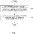
- FIG. 1 is a schematic flow diagram illustrating an example of a method of image reconstruction based on image data from a photon-counting multi-bin x-ray detector according to an embodiment.
- the method basically comprises the following steps:
- the determined parameter(s) may be used for adjustments in the image reconstruction procedure, e.g. to enable accurate material basis decomposition and/or artifact reduction. This may be important, e.g. in spectral computed tomography.
- the determined parameter(s) may be used with any suitable conventional image reconstruction procedure, including e.g. material basis decomposition methods and/or methods for artifact reduction.
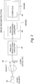
- an x-ray imaging system comprises an x-ray source 10, which emits x-rays; an x-ray detector 20, which detects the x-rays after they have passed through the object; analog processing circuitry 30, which processes the raw electrical signal from the detector and digitizes it; digital processing circuitry 40 which may carry out further processing operations on the measured data such as applying corrections, storing it temporarily, or filtering; and a digital computer 50 which stores the processed data and may perform further post-processing and/or image reconstruction.
- the overall detector may be regarded as the x-ray detector 20, or the x-ray detector 20 combined with the associated analog processing circuitry 30.
- the digital part including the digital processing circuitry 40 and/or the computer 50 may be regarded as an image reconstruction system 100/200, which performs image reconstruction based on the image data from the x-ray detector.
- the image reconstruction system 100/200 may thus be seen as the computer 50, or alternatively the combined system of the digital processing circuitry 40 and the computer 50, or possibly the digital processing circuitry 40 by itself if the digital processing circuitry is further specialized also for image reconstruction.
- the detector is a photon-counting detector as shown in Fig. 3 together with associated analog processing electronics.
- the detector 20 includes a reverse-biased photodiode where the photons interact and generate current pulses which are amplified by an amplifier and further processed by a filter to attain a desired pulse shape.
- Each pulse is then compared to a number N of thresholds T 1 ,..., T N using comparators, and a decoder circuit processes the comparator output signals and increments one of several counters, corresponding to the highest threshold which is lower than the pulse height.
- the incident x-ray spectrum is divided into a number N of energy bins with one counter each counting the number of registered photons in that bin.
- the counter values form the raw data that is read out from the detector and, possibly after further processing in digital processing circuitry, stored by the computer.
- the proposed technology provides parameter(s) of a given functional form of the relationship between comparator settings expressed in voltage in the read-out chain of the x-ray detector and the corresponding energy threshold values. Then resulting parameter(s) are then used in the subsequent image reconstruction procedure.
- the proposed technology thus partly relates to a mapping between threshold settings and corresponding energy.
- the reference pulse height spectrum may be expressed in units of energy and the measured pulse height spectrum expressed in units of voltage.
- the first set of data representative of a measured pulse height spectrum is based on a measured x-ray spectrum
- the second set of data representative of a reference pulse height spectrum is based on a previously acquired reference x-ray spectrum or a simulated x-ray spectrum.
- the fitting procedure may be performed between a measured accumulated x-ray spectrum and a simulated accumulated x-ray spectrum, taking physical detector characteristics into consideration in the simulation.
- the fitting procedure is performed between a measured accumulated x-ray spectrum and a previously acquired accumulated x-ray spectrum.
- the first set of data representative of a measured pulse height spectrum corresponds to a differentiated version of a measured accumulated x-ray spectrum
- the second set of data representative of an accumulated reference pulse height spectrum corresponds to a differentiated version of the accumulated reference x-ray spectrum.
- a measured accumulated x-ray spectrum, and a corresponding reference accumulated x-ray spectrum may be differentiated, and the fitting procedure may then be performed between the differentiated measured accumulated x-ray spectrum and the differentiated accumulated reference x-ray spectrum.
- the number of measurement points and their setting in voltage are chosen so that the corresponding differentiated x-ray spectrum is a histogram of counts in each detection bin, and the parameter(s) is/are determined based on histogram data for each of a number of channels in the read-out chain of the x-ray detector and corresponding reference histogram data.
- a broad x-ray spectrum of the x-ray source associated with the imaging modality is used to acquire an accumulated spectrum of counts as a function of comparator voltage, and the first set of data representative of a measured pulse height spectrum is based on the acquired accumulated spectrum of counts.
- the fitting procedure may be performed for each of a number of channels in the read-out chain of the x-ray detector.
- the interacting x-ray quantum generates a voltage pulse the height of which is proportional to the energy deposited in the sensor by the incident x-ray quantum. This height is compared to a multitude of comparators with tunable voltages. These comparators are denoted thresholds and the voltage span between adjacent thresholds defines a bin. When an x-ray deposits energy that results in a voltage pulse falling within a certain bin, the corresponding counter is incremented and this is how energy information is extracted in a photon counting multi-bin detector.
- the gain and the offset can differ between channels as illustrated in FIG. 4 and FIG. 5 .
- An event depositing E in channel i results in a pulse amplitude U i whereas in channel j an amplitude U j is obtained.
- One method to remove ring artifacts is by means of post processing the sinogram or the reconstructed image; in essence an algorithm searches for stripes or circles and applies some correction scheme on the thus identified pixels.
- Another method to reduce is to "reshuffle" the raw counts among the bins using an affine transformation. This is described, e.g. in reference: M. Persson and H. Bornefalk, "A Framework for Evaluating Threshold Variation Compensation Methods in Photon Counting Spectral CT", IEEE Transactions on Medical Imaging, vol. 31, no. 10, pp. 1861-1874, Oct. 2012 .
- the method either requires excessive calibration measurements, where the relative spectral response of all channels is determined for a multitude of combinations of x-ray spectral shape, tissue combinations and thicknesses, or the method requires accurate knowledge of the thresholds for each channel in keV. Utilizing the latter information the spectral response, i.e.
- r is the position vector, ⁇ T k ⁇ the set of thresholds in keV, ⁇ ( E ) the x-ray spectrum (number of photons per unit energy), R ( E,E ') the energy response function of the detector (such that R ( E,E ') denotes the probability of an incident x-ray photon of energy E deposits energy E' in the detector).
- N 0 is the unattenuated fluence directed towards the detector element x' at rotation angle ⁇ . Details can be found in reference: E. Roessl and R. Proksa, "K-edge imaging in x-ray computed tomography using multi-bin photon counting detectors", Phys. Med. Biol. 52 (2007) 4679-4696 .
- each voxel V ( r ) can be broken down into soft tissue content, bone content and lipid content. Such a break down can be beneficial for Monte Carlo based dose planning programs and has the potential to improve dose planning for radiation treatment purposes.
- a second use of basis decomposition is to reconstruct the entire energy dependence of the linear attenuation coefficient of each voxel.
- a i can be determined via an implementation of the inverse radon transform (in tomographic imaging) to generate the ML estimates of a 1 ⁇ and a 2 ⁇ .
- ⁇ * ( r ; E ) of Eq. (5) can for instance be used for displaying synthetic monoenergetic images by selecting a display energy E" and insert in Eq. (4). This is a popular method for contrast enhancement and is implemented on the work stations of some CT vendors.
- the set of thresholds in keV need to be known accurately.
- these thresholds can be determined with arbitrary accuracy by threshold scans utilizing synchrotron radiation, as set forth in reference Liu et al, "A silicon-strip detector for photon-counting spectral CT: energy resolution from 40 keV to 120 keV," IEEE Transactions on Nuclear Science, 61(3):1099-1105, 2014 , or with radioactive isotopes.
- the threshold is initially set to a high value resulting in zero registered counts since the monochromatic radiation results in pulses lower than the threshold.
- the dots are measurements and the solid line is fitted to the data. Given a constant flux and detector read out time, the number of detected counts will increase as the threshold is decreased. The point on the x-axis that corresponds to the point on the curve with the steepest slope is the threshold that corresponds to the particular monoenergetic energy applied.
- the value at the x-axis of the point of maximum slope corresponds is the DAC-setting or mV that corresponds to the monochromatic beam energy. If the beam energy is now changed and the procedure repeated, the DAC-settings or threshold voltages that correspond to a range of monochromatic beam energies can be determined from which the gain and offset of Eq. (1) can be determined from a linear regression.
- CT-detectors are known to drift over time (for instance the set of thresholds ⁇ T i ⁇ for each channel can change somewhat from day-to-day). For that reason it is common practice to perform a detector calibration each morning. Since high-flux monochromatic radiation sources are not readily available in the clinics there is a need for an accurate method of threshold determination or, equivalently, determining the gain and threshold of each channel according to Eq. (2), utilizing something other than monochromatic x-ray radiation.
- parameters such as gain and offset for each channel can be accurately determined, e.g. using the broad x-ray spectrum of the x-ray imaging modality.
- the method is robust and also fast and can therefore be performed in daily routine.
- the method allows the comparator thresholds to first be set in millivolts or DAC-values and the exact corresponding threshold in kilo electron volts (keV) can then be determined from Eq. (1).
- the material basis decomposition can be performed using the forward model of Eq. (2) and there is no reason to revert to procedures that utilize physical calibration phantoms.
- An alternative but more time consuming method of mapping the internal thresholds against x-ray photon energy is to use several exposures with different applied x-ray tube acceleration voltages. It is then possible to scan a threshold from a low setting to a higher and note the threshold setting when the detected fluence suddenly drops to zero; the last threshold that registered counts then corresponds to an x-ray energy equal to the x-ray tube acceleration voltage multiplied with the charge of one electron (if the acceleration voltage is 100 kV the threshold corresponds to 100 keV). This method however requires multiple threshold scans for many different x-ray spectra.
- a method to determine parameters such as the gain and offset of individual detector channels by fitting a reference pulse-height spectrum to a measured pulse height spectrum.
- the measured spectrum may be obtained by scanning a comparator threshold across a range of pulse height amplitudes, resulting in an accumulated x-ray spectrum in units of mV (denoted S-curve).
- the reference spectrum is tabulated. Such tabulation can be achieved by means of either detailed Monte Carlo simulations that takes into account the physical characteristics of the detector, such as charge sharing, response function, detection efficiency, pileup etc, or by measuring the x-ray spectrum with a reference detector.
- parts of the reference spectrum is generated in real time using the known detector characteristics as input.
- the measured pulse height spectrum will differ from the reference spectrum in two ways; the amplitude and the scale of the abscissa. Whereas the simulated spectrum is determined in units of keV the measures is in units of mV or comparator settings (DAC).
- DAC comparator settings
- a method to determine the gain and offset according to Eq. (1) whereby the parameters g i and m i of each channel i is determined by adjusting a simulated pulse-height spectrum to a measured one.
- the measured spectrum is obtained by scanning a comparator threshold across the range of detectable pulse amplitudes given a specified x-ray input spectrum (typically assumed a 120 kVp Tungsten spectrum with added aluminum filtration).
- a specified x-ray input spectrum typically assumed a 120 kVp Tungsten spectrum with added aluminum filtration.
- the total number of counts above threshold is accumulated during a fixed measurement time, resulting in an integral spectrum in units of mV ( FIG. 6 ).
- a simulated spectrum is generated with the aid of a detailed Monte Carlo simulation that takes into account all physical characteristics of the x-ray imaging chain. These include but are not limited to x-ray spectrum, detection efficiency, charge sharing, flux and accompanied pileup, possible fluorescent emission, incomplete charge collection, object scatter, detector response function, diode misalignment, electronic noise and interaction depth in the detector as captured by the depth segment number.
- the total number of x-ray events simulated is left as an open parameter (scale factor), affecting only the amplitude of the accumulated pulse height spectrum.
- the simulated photon interactions are used to form an integral spectrum of deposited energies in units of keV ( FIG 7 ). Note that low energy photons are preferentially absorbed in the top layer, with segment number 1.
- Equation (1) now directly represents the relationship between the abscissae of the measured and simulated spectrum, such that gain and offset (and the amplitude scale factor) can be estimated using a fitting procedure.
- gain and offset and the amplitude scale factor
- Several such fitting procedures are possible; the least squares, the weighted least square and the maximum likelihood are all common and plausible choices. Below we show how the weighted least squares method can be implemented.
- x l mV y l be the set of measured data points of FIG. 8 .
- the scale of the x-axis corresponds to the keV-scale of the model. This means that x l mV are the threshold settings in mV (or possible DAC settings) and ⁇ y l ⁇ the corresponding counts above the threshold.
- l is a measurement index ranging from 1 to the maximum number of measurements performed.
- the set ⁇ ⁇ j ⁇ i comprises all forward model parameters characteristic for channel i, such as detection efficiency, threshold setting in mV, charge sharing, scatter, depth segment, etc and are assumed to be known (as in the case of applied voltage to the comparators to determine the thresholds in mV) or to follow first principles as common in Monte Carlo simulation work (for the detection efficiency). Note that parameters will differ from channel to channel due to inhomogeneities such as different degree of electronic noise, possible misalignment of sensor diodes etc.
- ⁇ is a scale factor dependent on x-ray flux and measurement window time.
- x-ray spectra for instance varying kVp, filter thickness and material and flux
- a reference detector acting as ground truth
- lookup tables a previously acquired spectrum is used for the function F in Eq. (7), effectively mapping measured accumulated spectra to a common default accumulated spectra thereby achieving the goal of minimizing the effect of channel-to-channel differences.
- FIG. 9 the effect of high flux on pileup, and the resulting shift of the accumulated spectrum, is shown.
- Three x-ray spectra with input count rates of 2.5 Mcps/mm 2 , 25 Mcps/mm 2 and 250 Mcps/mm 2 are used. This particular illustration shows the distributions are shown for segment 7.
- FIG. 7 the dependence of interaction depth in the sensor diode is shown (for larger segment numbers, i.e. deeper interaction location, the spectrum is shifted toward higher energies a mechanism commonly denoted beam hardening).
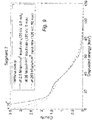
- FIG. 8 The results of the actual fitting procedure are shown in FIG. 8 , showing an excellent agreement between the simulated and measured spectra.
- ⁇ j 2 is the estimated variance (mean square error or the parameter estimate) for parameter j in ⁇ ⁇ j ⁇ i .
- tabulated linear attenuation coefficient needed for deriving the detection efficiency of the detector material is stated to have an error in the order of 1%.
- bias in the estimated keV-thresholds might not be the only limitation to the practical usefulness of the technique.
- the variance i.e. statistical uncertainty around the bias
- x l mV is needed to push the statistical component of the total threshold uncertainty down to close to zero.
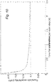
- FIG. 10 This is illustrated in FIG. 10 and indicates that the method not only has the capability to determine photon counting multi-bin spectral CT thresholds accurately enough, but also quickly, such that a the entire procedure can be carried on in a matter of minutes and thus allow careful recalibration of energy threshold in the clinical routine, a key advantage to other methods requiring time consuming procedures.
- Using a calibration time of 2 second per 1-keV scan step at the particular count rate used in the simulations resulting in this result the statistical contribution is negligible and the keV-uncertainty of a calibrated threshold is only limited by systematics.
- U k is the externally applied comparator setting in mV which via Eq. (1) is converted to a corresponding energy threshold setting in keV.
- Fitting the measured histogram data to simulated data using Eq. (2), and keeping m i and g i as free parameters, is therefore clearly a closely related implementation to the disclosed invention.
- the difference lies only in differentiating the s-curve measurement and selecting the sampling points x l mV such that they coincide with the desired bin edges.
- embodiments may be implemented in hardware, or in software for execution by suitable processing circuitry, or a combination thereof.
- Particular examples include one or more suitably configured digital signal processors and other known electronic circuits, e.g. discrete logic gates interconnected to perform a specialized function, or Application Specific Integrated Circuits (ASICs).
- digital signal processors and other known electronic circuits, e.g. discrete logic gates interconnected to perform a specialized function, or Application Specific Integrated Circuits (ASICs).
- ASICs Application Specific Integrated Circuits
- At least some of the steps, functions, procedures, modules and/or blocks described herein may be implemented in software such as a computer program for execution by suitable processing circuitry such as one or more processors or processing units.
- processing circuitry includes, but is not limited to, one or more microprocessors, one or more Digital Signal Processors (DSPs), one or more Central Processing Units (CPUs), video acceleration hardware, and/or any suitable programmable logic circuitry such as one or more Field Programmable Gate Arrays (FPGAs), or one or more Programmable Logic Controllers (PLCs).
- DSPs Digital Signal Processors
- CPUs Central Processing Units
- FPGAs Field Programmable Gate Arrays
- PLCs Programmable Logic Controllers
- the proposed technology thus provides an image reconstruction system configured to perform the method described herein.
- an apparatus for image reconstruction based on image data from a photon-counting multi-bin x-ray detector configured to determine parameters of a given functional form of the relationship between assigned comparator settings expressed in voltage in the read-out chain of the x-ray detector and the corresponding energy threshold values expressed in energy based on a fitting procedure between a first set of data representative of a measured pulse height spectrum and a second set of data representative of a reference pulse height spectrum.
- the apparatus is further configured to perform image reconstruction based on the image data and the determined parameters.
- the apparatus 100 comprises a processor 110 and a memory 120, the memory comprising instructions executable by the processor, whereby the processor is operative to determine the parameters and perform the image reconstruction, as illustrated in FIG. 11 .
- the apparatus comprises an input/output interface for receiving input data and outputting resulting output data.
- processors including one or more processors.
- the processor(s) and memory are interconnected to each other to enable normal software execution.
- An optional input/output device may also be interconnected to the processor(s) and/or the memory to enable input and/or output of relevant data such as input parameter(s) and/or resulting output parameter(s).
- processor' should be interpreted in a general sense as any system or device capable of executing program code or computer program instructions to perform a particular processing, determining or computing task.
- the processing circuitry including one or more processors is thus configured to perform, when executing the computer program, well-defined processing tasks such as those described herein.
- the processing circuitry does not have to be dedicated to only execute the above-described steps, functions, procedure and/or blocks, but may also execute other tasks.
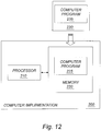
- FIG. 12 is a schematic diagram illustrating another example of computer implementation according to an embodiment.
- a computer program 225; 235 for use with a photon-counting multi-bin x-ray detector.
- the computer program 225; 235 comprises instructions, which when executed by at least one processor 110; 210, cause the at least one processor to:
- the proposed technology also provides a computer-program product comprising a computer-readable medium 220; 230) having stored thereon such a computer program.
- the software or computer program 225; 235 may be realized as a computer program product, which is normally carried or stored on a computer-readable medium 220; 230, in particular a non-volatile medium.
- the computer-readable medium may include one or more removable or non-removable memory devices including, but not limited to a Read-Only Memory (ROM), a Random Access Memory (RAM), a Compact Disc (CD), a Digital Versatile Disc (DVD), a Blu-ray disc, a Universal Serial Bus (USB) memory, a Hard Disk Drive (HDD) storage device, a flash memory, a magnetic tape, or any other conventional memory device.
- the computer program may thus be loaded into the operating memory of a computer or equivalent processing device for execution by the processing circuitry thereof.
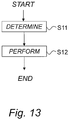
- the flow diagram or diagrams presented herein may be regarded as a computer flow diagram or diagrams, an example of which is illustrated in FIG. 13 , when performed by one or more processors.
- a corresponding device, system and/or apparatus may be defined as a group of function modules, where each step performed by the processor corresponds to a function module.
- the function modules are implemented as a computer program running on the processor.
- the device, system and/or apparatus may alternatively be defined as a group of function modules, where the function modules are implemented as a computer program running on at least one processor.
- the computer program residing in memory may thus be organized as appropriate function modules configured to perform, when executed by the processor, at least part of the steps and/or tasks described herein.
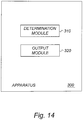
- FIG. 14 is a schematic diagram illustrating an example of an apparatus for supporting image reconstruction.
- the apparatus 300 is adapted for supporting image reconstruction based on image data from a photon-counting x-ray detector.
- the apparatus 300 comprises a determination module 310 for determining parameters of a given functional form of the relationship between assigned comparator settings expressed in voltage in the read-out chain of the x-ray detector and the corresponding energy threshold values expressed in energy based on a fitting procedure between a first set of data representative of a measured pulse height spectrum and a second set of data representative of a reference pulse height spectrum.
- the apparatus 300 also comprises an output module 320 for outputting the determined parameters to an image reconstruction system for enabling adjustments in the image reconstruction procedure based on the determined parameters.
- modules in FIG. 14 may be realized predominantly by hardware modules, or alternatively by hardware.
- the extent of software versus hardware is purely implementation selection.
Landscapes
- Health & Medical Sciences (AREA)
- Life Sciences & Earth Sciences (AREA)
- Engineering & Computer Science (AREA)
- Physics & Mathematics (AREA)
- Medical Informatics (AREA)
- High Energy & Nuclear Physics (AREA)
- Molecular Biology (AREA)
- General Health & Medical Sciences (AREA)
- Pathology (AREA)
- General Physics & Mathematics (AREA)
- Optics & Photonics (AREA)
- Biophysics (AREA)
- Heart & Thoracic Surgery (AREA)
- Radiology & Medical Imaging (AREA)
- Surgery (AREA)
- Animal Behavior & Ethology (AREA)
- Nuclear Medicine, Radiotherapy & Molecular Imaging (AREA)
- Public Health (AREA)
- Veterinary Medicine (AREA)
- Biomedical Technology (AREA)
- Spectroscopy & Molecular Physics (AREA)
- Chemical & Material Sciences (AREA)
- Analytical Chemistry (AREA)
- Biochemistry (AREA)
- Immunology (AREA)
- Signal Processing (AREA)
- Theoretical Computer Science (AREA)
- Multimedia (AREA)
- Computer Vision & Pattern Recognition (AREA)
- Toxicology (AREA)
- General Life Sciences & Earth Sciences (AREA)
- Geophysics (AREA)
- Apparatus For Radiation Diagnosis (AREA)
- Measurement Of Radiation (AREA)
Description
- The proposed technology generally relates to x-ray imaging and corresponding imaging reconstruction and imaging tasks. In particular, the proposed technology relates to a method of image reconstruction based on image data from a photon-counting multi-bin x-ray detector, and a corresponding image reconstruction system and apparatus for image reconstruction, and a corresponding computer program and computer-program product, as well as apparatus for supporting image reconstruction based on image data from a photon-counting x-ray detector.
- Radiographic imaging such as x-ray imaging has been used for years in medical applications and for non-destructive testing.
- Normally, an x-ray imaging system includes an x-ray source and an x-ray detector consisting of multiple detector elements. The x-ray source emits x-rays, which pass through a subject or object to be imaged and are then registered by the detector. Since some materials absorb a larger fraction of the x-rays than others, an image is formed of the subject or object.
- In the electronic read out chain of a direct conversion energy-sensitive multi-bin detector, the interacting x-ray quantum generates a voltage pulse the height of which is proportional to the energy deposited in the sensor by the incident x-ray quantum. This height is compared in a multitude of comparators with tunable voltage settings. These comparator settings are often denoted thresholds and the voltage span between adjacent thresholds defines a so-called bin. When an x-ray deposits energy that results in a voltage pulse falling within a certain bin, a corresponding counter is incremented and this is how energy information is extracted in a photon-counting multi-bin detector.
- However, x-ray imaging systems based on photon-counting multi-bin detectors still suffer from artifacts in the reconstructed image and also make material basis decomposition of the spectral data difficult.
- There is thus a general demand to improve radiographic imaging such as x-ray imaging.
- It is an object to provide an improved method of image reconstruction.
- These and other objects are met by embodiments of the proposed technology.
- According to a first aspect, there is provided a method of image reconstruction based on image data from a photon-counting multi-bin x-ray detector. The method comprises:
- determining parameter(s) of a given functional form of the relationship between comparator settings expressed in voltage in the read-out chain of the x-ray detector and the corresponding energy threshold values expressed in energy based on a fitting procedure between a first set of data representative of a measured pulse height spectrum and a second set of data representative of a reference pulse height spectrum;
- performing image reconstruction based on the image data and the determined parameter(s).
- According to a second aspect, there is provided an image reconstruction system configured to perform the above method.
- According to a third aspect, there is provided an apparatus for image reconstruction based on image data from a photon-counting multi-bin x-ray detector. The apparatus is configured to determine parameters of a given functional form of the relationship between assigned comparator settings expressed in voltage in the read-out chain of the x-ray detector and the corresponding energy threshold values expressed in energy based on a fitting procedure between a first set of data representative of a measured pulse height spectrum and a second set of data representative of a reference pulse height spectrum. The apparatus is further configured to perform image reconstruction based on the image data and the determined parameters.
- According to a fourth aspect, there is provided a computer program for use with a photon-counting multi-bin x-ray detector. The computer program comprises instructions, which when executed by at least one processor, cause the at least one processor to:
- determine parameters of a given functional form of the relationship between assigned comparator settings expressed in voltage in the read-out chain of the x-ray detector and the corresponding energy threshold values expressed in energy based on a fitting procedure between a first set of data representative of a measured pulse height spectrum and a second set of data representative of a reference pulse height spectrum, and
- perform image reconstruction based on image data from the x-ray detector and the determined parameters.
- According to a fifth aspect, there is provided a computer-program product comprising a computer-readable medium having stored thereon a computer program as defined above.
- According to a sixth aspect, there is provided an apparatus for supporting image reconstruction based on image data from a photon-counting x-ray detector. The apparatus comprises a determination module for determining parameters of a given functional form of the relationship between assigned comparator settings expressed in voltage in the read-out chain of the x-ray detector and the corresponding energy threshold values expressed in energy based on a fitting procedure between a first set of data representative of a measured pulse height spectrum and a second set of data representative of a reference pulse height spectrum. The apparatus also comprises an output module for outputting the determined parameters to an image reconstruction system for enabling adjustments in the image reconstruction procedure based on the determined parameters.
- In this way, efficient high-quality image reconstruction can be achieved. By way of example, the determined parameter(s) may be used for adjustments in the image reconstruction procedure, e.g. to enable accurate material basis decomposition and/or artifact reduction. This may be important, e.g. in spectral computed tomography.
- Other advantages will be appreciated when reading the detailed description.
- The invention is defined by the independent claim, with further embodiments in the dependent claims.
- The embodiments, together with further objects and advantages thereof, may best be understood by making reference to the following description taken together with the accompanying drawings, in which:
-
FIG. 1 is a schematic flow diagram illustrating an example of a method of image reconstruction based on image data from a photon-counting multi-bin x-ray detector according to an embodiment. -
FIG. 2 is a schematic diagram illustrating an example of an x-ray imaging system. -
FIG. 3 is a schematic diagram illustrating an example of a photon-counting detector with several energy thresholds. -
FIG. 4 is a schematic diagram illustrating an example of how gain values as determined from multiple s-curve scans with monochromatic rays of different energy differ between channels, where the error bars indicate the statistical uncertainty. -
FIG. 5 is a schematic diagram illustrating an example of how offset values as determined from multiple s-curve scans with monochromatic rays of different energy differ between channels. -
FIG. 6 is a schematic diagram illustrating an example of the result of a threshold scan of a monochromatic source. -
FIG. 7 is a schematic diagram illustrating an example of cumulative (integrated) spectra of deposited energies, as obtained in three different depth segments. -
FIG. 8 is a schematic diagram illustrating an example of a particular measured accumulated pulse-height spectra and corresponding fitted models for three segments. -
FIG. 9 is a schematic diagram illustrating an example of a cumulative (integrated) spectra of deposited energies with and without pileup effect. -
FIG. 10 is a schematic diagram illustrating an example of the threshold uncertainty as a function of measurement time per scan step, evaluated for a systematic uncertainty of 0.1 keV. -
FIG. 11 is a schematic diagram illustrating an example of a system/apparatus for image reconstruction according to an embodiment. -
FIG. 12 is a schematic diagram illustrating an example of computer implementation according to an embodiment. -
FIG. 13 is a schematic diagram illustrating an example of a computer flow diagram according to an embodiment. -
FIG. 14 is a schematic diagram illustrating an example of an apparatus for supporting image reconstruction. - Throughout the drawings, the same reference designations are used for similar or corresponding elements.
-
FIG. 1 is a schematic flow diagram illustrating an example of a method of image reconstruction based on image data from a photon-counting multi-bin x-ray detector according to an embodiment. - The method basically comprises the following steps:
- S1: Determining parameter(s) of a given functional form of the relationship between comparator settings expressed in voltage in the read-out chain of the x-ray detector and the corresponding energy threshold values expressed in energy based on a fitting procedure between a first set of data representative of a measured pulse height spectrum and a second set of data representative of a reference pulse height spectrum.
- S2: Performing image reconstruction based on the image data and the determined parameter(s).
- In this way, efficient high-quality image reconstruction can be achieved. By way of example, the determined parameter(s) may be used for adjustments in the image reconstruction procedure, e.g. to enable accurate material basis decomposition and/or artifact reduction. This may be important, e.g. in spectral computed tomography. The determined parameter(s) may be used with any suitable conventional image reconstruction procedure, including e.g. material basis decomposition methods and/or methods for artifact reduction.
- For a better understanding of the invention it may be useful to briefly describe a non-limiting example of an x-ray imaging system.
- As illustrated in the example of
Fig. 2 , an x-ray imaging system comprises anx-ray source 10, which emits x-rays; anx-ray detector 20, which detects the x-rays after they have passed through the object;analog processing circuitry 30, which processes the raw electrical signal from the detector and digitizes it;digital processing circuitry 40 which may carry out further processing operations on the measured data such as applying corrections, storing it temporarily, or filtering; and adigital computer 50 which stores the processed data and may perform further post-processing and/or image reconstruction. The overall detector may be regarded as thex-ray detector 20, or thex-ray detector 20 combined with the associatedanalog processing circuitry 30. The digital part including thedigital processing circuitry 40 and/or thecomputer 50 may be regarded as animage reconstruction system 100/200, which performs image reconstruction based on the image data from the x-ray detector. Theimage reconstruction system 100/200 may thus be seen as thecomputer 50, or alternatively the combined system of thedigital processing circuitry 40 and thecomputer 50, or possibly thedigital processing circuitry 40 by itself if the digital processing circuitry is further specialized also for image reconstruction. - In a particular example, the detector is a photon-counting detector as shown in
Fig. 3 together with associated analog processing electronics. In this example, thedetector 20 includes a reverse-biased photodiode where the photons interact and generate current pulses which are amplified by an amplifier and further processed by a filter to attain a desired pulse shape. Each pulse is then compared to a number N of thresholds T 1,...,TN using comparators, and a decoder circuit processes the comparator output signals and increments one of several counters, corresponding to the highest threshold which is lower than the pulse height. In this way, the incident x-ray spectrum is divided into a number N of energy bins with one counter each counting the number of registered photons in that bin. The counter values form the raw data that is read out from the detector and, possibly after further processing in digital processing circuitry, stored by the computer. - As indicated, the proposed technology provides parameter(s) of a given functional form of the relationship between comparator settings expressed in voltage in the read-out chain of the x-ray detector and the corresponding energy threshold values. Then resulting parameter(s) are then used in the subsequent image reconstruction procedure.
The proposed technology thus partly relates to a mapping between threshold settings and corresponding energy.
By way of example, the reference pulse height spectrum may be expressed in units of energy and the measured pulse height spectrum expressed in units of voltage.
In a particular example, the first set of data representative of a measured pulse height spectrum is based on a measured x-ray spectrum, and the second set of data representative of a reference pulse height spectrum is based on a previously acquired reference x-ray spectrum or a simulated x-ray spectrum.
For example, the fitting procedure may be performed between a measured accumulated x-ray spectrum and a simulated accumulated x-ray spectrum, taking physical detector characteristics into consideration in the simulation. - The fitting procedure is performed between a measured accumulated x-ray spectrum and a previously acquired accumulated x-ray spectrum.
- In a particular example, the first set of data representative of a measured pulse height spectrum corresponds to a differentiated version of a measured accumulated x-ray spectrum, and the second set of data representative of an accumulated reference pulse height spectrum corresponds to a differentiated version of the accumulated reference x-ray spectrum.
For example, a measured accumulated x-ray spectrum, and a corresponding reference accumulated x-ray spectrum may be differentiated, and the fitting procedure may then be performed between the differentiated measured accumulated x-ray spectrum and the differentiated accumulated reference x-ray spectrum. - Optionally, the number of measurement points and their setting in voltage are chosen so that the corresponding differentiated x-ray spectrum is a histogram of counts in each detection bin, and the parameter(s) is/are determined based on histogram data for each of a number of channels in the read-out chain of the x-ray detector and corresponding reference histogram data.
- By way of example, a broad x-ray spectrum of the x-ray source associated with the imaging modality is used to acquire an accumulated spectrum of counts as a function of comparator voltage, and the first set of data representative of a measured pulse height spectrum is based on the acquired accumulated spectrum of counts.
- With regard to the parameter(s) of the functional form of the relationship between comparator settings expressed in voltage in the read-out chain of the x-ray detector and the corresponding energy threshold values, different options exist.
- By way of example, the parameter(s) may include an array pi of one or more parameters relating the voltage Ui of the measured pulse height spectrum with the energy Ei of the reference pulse height spectrum according to:

- As an example, the parameters may include gain gi and offset mi relating the voltage Ui of the measured pulse height spectrum with the energy Ei of the reference pulse height spectrum according to:

- For example, the fitting procedure may be performed for each of a number of channels in the read-out chain of the x-ray detector.
- In the following, the proposed technology will be described with reference to various non-limiting examples. It should though be understood that the invention is not limited thereto.
- As discussed, in the electronic read out chain of direct conversion energy sensitive multi-bin detectors the interacting x-ray quantum generates a voltage pulse the height of which is proportional to the energy deposited in the sensor by the incident x-ray quantum. This height is compared to a multitude of comparators with tunable voltages. These comparators are denoted thresholds and the voltage span between adjacent thresholds defines a bin. When an x-ray deposits energy that results in a voltage pulse falling within a certain bin, the corresponding counter is incremented and this is how energy information is extracted in a photon counting multi-bin detector.
- The tunable comparators or thresholds are set in millivolts. For the same deposited energy in the sensor (typically in the range of 30-140 keV), inhomogeneities in the electronic components result in slightly different pulse heights in millivolts. Typically each channel presents a linear relationship between deposited energy in keV and the pulse height. For channel i it thus holds that a deposited energy E (keV) results in a peak amplitude of Ui (mV), where:

- The gain and the offset can differ between channels as illustrated in
FIG. 4 andFIG. 5 . Reference can be made to, e.g. C. Xu et al. "Evaluation of a second-generation ultra-fast energy-resolved ASIC for photon-counting spectral CT" IEEE Transactions on Nuclear Science, vol. 60, no. 1, pp. 437-445, Feb. 2013. An event depositing E in channel i results in a pulse amplitude Ui whereas in channel j an amplitude Uj is obtained. If an internal threshold T is located such that Ui < T < Uj, or Uj< T < Ui , the same energy photon will result in a signal in different bins in different channels (pixel location). This will result in ring artifacts in the reconstructed image and also make material basis decomposition of the spectral data difficult. - One method to remove ring artifacts is by means of post processing the sinogram or the reconstructed image; in essence an algorithm searches for stripes or circles and applies some correction scheme on the thus identified pixels. Another method to reduce is to "reshuffle" the raw counts among the bins using an affine transformation. This is described, e.g. in reference: M. Persson and H. Bornefalk, "A Framework for Evaluating Threshold Variation Compensation Methods in Photon Counting Spectral CT", IEEE Transactions on Medical Imaging, vol. 31, no. 10, pp. 1861-1874, Oct. 2012. While more direct (as no search of relative contrast changes is performed as in post-processing methods) the method either requires excessive calibration measurements, where the relative spectral response of all channels is determined for a multitude of combinations of x-ray spectral shape, tissue combinations and thicknesses, or the method requires accurate knowledge of the thresholds for each channel in keV. Utilizing the latter information the spectral response, i.e. distribution of counts across the bins, can be derived using a typical so called forward model of the imaging system where the expected number of counts in bin k, λk , after passage through an object with distribution of linear attenuation coefficients µ( r; E) is given by:

- In Eq. (2) r is the position vector, {Tk } the set of thresholds in keV, Φ (E) the x-ray spectrum (number of photons per unit energy), R(E,E') the energy response function of the detector (such that R(E,E') denotes the probability of an incident x-ray photon of energy E deposits energy E' in the detector). N 0 is the unattenuated fluence directed towards the detector element x' at rotation angle θ. Details can be found in reference: E. Roessl and R. Proksa, "K-edge imaging in x-ray computed tomography using multi-bin photon counting detectors", Phys. Med. Biol. 52 (2007) 4679-4696.
- In basis decomposition techniques applied to energy resolved CT the goal can be to break down the content of each voxel V( r ) into soft tissue content, bone content and lipid content. Such a break down can be beneficial for Monte Carlo based dose planning programs and has the potential to improve dose planning for radiation treatment purposes.
- A second use of basis decomposition, also well known to those skilled in the art, is to reconstruct the entire energy dependence of the linear attenuation coefficient of each voxel.
- Whereas standard energy integrating CT reconstructs the linear attenuation coefficient at each voxel at some average energy Ê the use of the Ansatz that µ(r; E) is written as a separable linear combination of two or more known energy bases:


- After



- The expression µ*( r; E) of Eq. (5) can for instance be used for displaying synthetic monoenergetic images by selecting a display energy E" and insert in Eq. (4). This is a popular method for contrast enhancement and is implemented on the work stations of some CT vendors.
- If the ML method is going to be used for accurate material decomposition, the parameters of the forward model (2) have to be known with a high degree of certainty. The same holds for the determination of the affine transformation to remove ring artifacts in energy weighting schemes as described in reference M. Persson and H. Bornefalk, "A Framework for Evaluating Threshold Variation Compensation Methods in Photon Counting Spectral CT", IEEE Transactions on Medical Imaging, vol. 31, no. 10, pp. 1861-1874, Oct. 2012.
- In particular {Ti }, the set of thresholds in keV, need to be known accurately. For detector prototypes these thresholds can be determined with arbitrary accuracy by threshold scans utilizing synchrotron radiation, as set forth in reference Liu et al, "A silicon-strip detector for photon-counting spectral CT: energy resolution from 40 keV to 120 keV," IEEE Transactions on Nuclear Science, 61(3):1099-1105, 2014, or with radioactive isotopes. In such a threshold scan (also known as s-curve measurement), the threshold is initially set to a high value resulting in zero registered counts since the monochromatic radiation results in pulses lower than the threshold. It is then lowered stepwise (in digital-to-analog converter (DAC) setting or mV) and the counts at each threshold are registered. When the there is no increase in counts any more the procedure is discontinued and the result is an s-curve as in
FIG. 6 . - The dots are measurements and the solid line is fitted to the data. Given a constant flux and detector read out time, the number of detected counts will increase as the threshold is decreased. The point on the x-axis that corresponds to the point on the curve with the steepest slope is the threshold that corresponds to the particular monoenergetic energy applied.
- The value at the x-axis of the point of maximum slope corresponds is the DAC-setting or mV that corresponds to the monochromatic beam energy. If the beam energy is now changed and the procedure repeated, the DAC-settings or threshold voltages that correspond to a range of monochromatic beam energies can be determined from which the gain and offset of Eq. (1) can be determined from a linear regression.
- The above method is time consuming and difficult to perform in clinical routine. CT-detectors are known to drift over time (for instance the set of thresholds {Ti } for each channel can change somewhat from day-to-day). For that reason it is common practice to perform a detector calibration each morning. Since high-flux monochromatic radiation sources are not readily available in the clinics there is a need for an accurate method of threshold determination or, equivalently, determining the gain and threshold of each channel according to Eq. (2), utilizing something other than monochromatic x-ray radiation.
- Preferably, one would want to use the x-ray spectrum of the existing x-ray tube attached to the system. Thus far, this has not been possible and instead one has had to revert to the use of calibration phantoms. The main idea in methods based on calibration phantoms is to obtain several x-ray exposures with differently composed objects in the beam path. Typically two or three basis materials are used with varying thicknesses. In the below example two basis functions f 1(E) and f 2(E) are used but the method is easily extended to higher dimensionality.
- Let [c 1,0,c 2,0 c 3,0 ,...,cN,0 ] T be the unattenuated counts in each
bin 

- If F is linear (a matrix) the system (6) can be solved in the least squares sense.
- Other functional forms have been suggested (polynomials) and variations of the method are described in at least the following publications:
- T. G. Schmidt, "An empirical method for correcting the detector spectral response in energy-resolved CT," in Medical Imaging 2012: Physics of Medical Imaging, Proc. SPIE 8313, 831312, SPIE 2012.
- R. E. Alvarez, "Estimator for photon counting energy selective x-ray imaging with multi-bin pulse height analysis", in Medical Physics, 38 (5), May 2011, p 2324
- S. Lee et al, "Quantitative material decomposition using spectral computed tomography with an energy-resolved photon-counting detector", Physics in Medicine and Biology, vol 59(18), p. 5457
- J. Jakubek, "Data processing and image reconstruction methods for pixel detectors," Nucl. Instr. and Meth. A, vol. 576, no. 1, pp. 223 - 234, Jun. 2007, proceedings of the 8th International Workshop on Radiation Imaging Detectors.
- Other examples of related prior art include:
-
US Patent 7,756,239 relates to a calibration procedure for multi-bin spectral x-ray imaging based on measuring the response in a plurality of energy bins of different combinations of materials and thicknesses and relating the bin response to the line integrals of the materials. -
US Patent 8,422,636 relates to a procedure in which discriminator thresholds are set in mV or DAC settings and shifting the thresholds relative to each other in order to minimize noise in the bin images. -
US Patent 7,983,397 relates to a method and apparatus for determining one or more characteristics of radiation based on a calibration operation to determine a transform from measured counts in bins to an estimate of the absorbed dose. -
US Patent 8,000,434 relates to method of reconstructing an energy spectrum that is distorted from charge sharing. -
US 2014/0105369 relates to a calibration apparatus and method that may be used for setting a magnitude of an electric pulse based on a result obtained by imaging at least one imaging object, and that may be used for mapping and calibrating a photon energy corresponding to an absorption edge of at least one calibration object. -
JP 2011/085479 -
US 2013/0301798 relates to a calibration method of a radiation detecting apparatus, a control method of a radiation imaging apparatus and a radiation imaging apparatus. The control method of the radiation imaging apparatus includes performing prior information acquisition by obtaining at least one correction threshold energy, at which a theoretical radiation intensity of at least one threshold energy is measured, and performing radiation image acquisition by obtaining at least one radiation image at the at least one threshold energy using the at least one correction threshold energy. - According to an example embodiment of the proposed technology, parameters such as gain and offset for each channel can be accurately determined, e.g. using the broad x-ray spectrum of the x-ray imaging modality. The method is robust and also fast and can therefore be performed in daily routine. The method allows the comparator thresholds to first be set in millivolts or DAC-values and the exact corresponding threshold in kilo electron volts (keV) can then be determined from Eq. (1). With accurate knowledge of individual channel thresholds, the material basis decomposition can be performed using the forward model of Eq. (2) and there is no reason to revert to procedures that utilize physical calibration phantoms.
- An alternative but more time consuming method of mapping the internal thresholds against x-ray photon energy, and not forming part of the claimed invention, is to use several exposures with different applied x-ray tube acceleration voltages. It is then possible to scan a threshold from a low setting to a higher and note the threshold setting when the detected fluence suddenly drops to zero; the last threshold that registered counts then corresponds to an x-ray energy equal to the x-ray tube acceleration voltage multiplied with the charge of one electron (if the acceleration voltage is 100 kV the threshold corresponds to 100 keV). This method however requires multiple threshold scans for many different x-ray spectra.
- In another example embodiment, there is no need for a threshold scan and instead the spread among the different energy bins is used to infer gain and offset (according to Eq. (1)) for each channel.
- In a non-limiting example embodiment, there is provided a method to determine parameters such as the gain and offset of individual detector channels by fitting a reference pulse-height spectrum to a measured pulse height spectrum. The measured spectrum may be obtained by scanning a comparator threshold across a range of pulse height amplitudes, resulting in an accumulated x-ray spectrum in units of mV (denoted S-curve). In a preferred embodiment, the reference spectrum is tabulated. Such tabulation can be achieved by means of either detailed Monte Carlo simulations that takes into account the physical characteristics of the detector, such as charge sharing, response function, detection efficiency, pileup etc, or by measuring the x-ray spectrum with a reference detector. In another embodiment, parts of the reference spectrum is generated in real time using the known detector characteristics as input.
- The measured pulse height spectrum will differ from the reference spectrum in two ways; the amplitude and the scale of the abscissa. Whereas the simulated spectrum is determined in units of keV the measures is in units of mV or comparator settings (DAC). This allows a fitting procedure of the measured data to the reference data with three free parameters; an amplitude scale factor and the gain gi and offset mi relating the coordinate Ui (in mV or DAC) of the abscissa of the measured pulse height spectrum with the energy E of the reference spectrum: Ui = giE + mi . Subscript i indicates that the fitting procedure is carried out individually for each channel i. The exact nature of the fitting procedure is not important; the least squares method and maximum likelihood methods are two popular choices.
- In this particular example, a method to determine the gain and offset according to Eq. (1) is disclosed whereby the parameters gi and mi of each channel i is determined by adjusting a simulated pulse-height spectrum to a measured one. The measured spectrum is obtained by scanning a comparator threshold across the range of detectable pulse amplitudes given a specified x-ray input spectrum (typically assumed a 120 kVp Tungsten spectrum with added aluminum filtration). At each scanned threshold position, expressed in a voltage in mV or a DAC setting, the total number of counts above threshold is accumulated during a fixed measurement time, resulting in an integral spectrum in units of mV (
FIG. 6 ). - In a preferred embodiment of the invention a simulated spectrum is generated with the aid of a detailed Monte Carlo simulation that takes into account all physical characteristics of the x-ray imaging chain. These include but are not limited to x-ray spectrum, detection efficiency, charge sharing, flux and accompanied pileup, possible fluorescent emission, incomplete charge collection, object scatter, detector response function, diode misalignment, electronic noise and interaction depth in the detector as captured by the depth segment number. The total number of x-ray events simulated is left as an open parameter (scale factor), affecting only the amplitude of the accumulated pulse height spectrum.
- The simulated photon interactions are used to form an integral spectrum of deposited energies in units of keV (
FIG 7 ). Note that low energy photons are preferentially absorbed in the top layer, withsegment number 1. - Equation (1) now directly represents the relationship between the abscissae of the measured and simulated spectrum, such that gain and offset (and the amplitude scale factor) can be estimated using a fitting procedure. Several such fitting procedures are possible; the least squares, the weighted least square and the maximum likelihood are all common and plausible choices. Below we show how the weighted least squares method can be implemented.
- Let

FIG. 8 . The scale of the x-axis corresponds to the keV-scale of the model. This means that
- The weighted least squares optimization problem for each channel can now be expressed as:


- In another embodiment of the invention a multitude of x-ray spectra (for instance varying kVp, filter thickness and material and flux) have been collected by a reference detector (acting as ground truth) and stored in lookup tables. In such an embodiment a previously acquired spectrum is used for the function F in Eq. (7), effectively mapping measured accumulated spectra to a common default accumulated spectra thereby achieving the goal of minimizing the effect of channel-to-channel differences.
- In
FIG. 9 the effect of high flux on pileup, and the resulting shift of the accumulated spectrum, is shown. Three x-ray spectra with input count rates of 2.5 Mcps/mm2, 25 Mcps/mm2 and 250 Mcps/mm2 are used. This particular illustration shows the distributions are shown forsegment 7. - In
FIG. 7 , the dependence of interaction depth in the sensor diode is shown (for larger segment numbers, i.e. deeper interaction location, the spectrum is shifted toward higher energies a mechanism commonly denoted beam hardening). The results of the actual fitting procedure are shown inFIG. 8 , showing an excellent agreement between the simulated and measured spectra. - Any misspecifications of the parameter set {φj } i will result in biased estimates of


- Naturally, bias in the estimated keV-thresholds might not be the only limitation to the practical usefulness of the technique. The variance (i.e. statistical uncertainty around the bias) may affect the ability to produce meaningful estimates. However, under typical x-ray exposure settings a mere one to two seconds of x-ray exposure for each mV-threshold setting

- This is illustrated in
FIG. 10 and indicates that the method not only has the capability to determine photon counting multi-bin spectral CT thresholds accurately enough, but also quickly, such that a the entire procedure can be carried on in a matter of minutes and thus allow careful recalibration of energy threshold in the clinical routine, a key advantage to other methods requiring time consuming procedures. Using a calibration time of 2 second per 1-keV scan step at the particular count rate used in the simulations resulting in this result, the statistical contribution is negligible and the keV-uncertainty of a calibrated threshold is only limited by systematics. - A slight verification of the described procedure would be to acquire not accumulated spectra as in
FIG. 6 through FIG. 9 , but instead use the distribution-like function of the x-ray energies (i.e. the differentiated version of the accumulated spectrum). If such a method is used, and the electronic comparator values applied (xmv ) are fixed and equal in number to the number of comparators/bins in the system, it is clear that the measured spectrum would correspond to a histogram of counts in each bin. Since gain and offset would differ between channels, and comparator settings are applied globally, one would expect the histograms of bin counts to differ from channel to channel. Using Eq. (2), the forward model could be changed to encompass the free parameters gi and mi of each channel, i.e. setting

- It will be appreciated that the methods and devices described herein can be combined and re-arranged in a variety of ways.
- For example, embodiments may be implemented in hardware, or in software for execution by suitable processing circuitry, or a combination thereof.
- The steps, functions, procedures, modules and/or blocks described herein may be implemented in hardware using any conventional technology, such as discrete circuit or integrated circuit technology, including both general-purpose electronic circuitry and application-specific circuitry.
- Particular examples include one or more suitably configured digital signal processors and other known electronic circuits, e.g. discrete logic gates interconnected to perform a specialized function, or Application Specific Integrated Circuits (ASICs).
- Alternatively, at least some of the steps, functions, procedures, modules and/or blocks described herein may be implemented in software such as a computer program for execution by suitable processing circuitry such as one or more processors or processing units.
- Examples of processing circuitry includes, but is not limited to, one or more microprocessors, one or more Digital Signal Processors (DSPs), one or more Central Processing Units (CPUs), video acceleration hardware, and/or any suitable programmable logic circuitry such as one or more Field Programmable Gate Arrays (FPGAs), or one or more Programmable Logic Controllers (PLCs).
- It should also be understood that it may be possible to re-use the general processing capabilities of any conventional device or unit in which the proposed technology is implemented. It may also be possible to re-use existing software, e.g. by reprogramming of the existing software or by adding new software components.
- The proposed technology thus provides an image reconstruction system configured to perform the method described herein.
- In particular, there is provided an apparatus for image reconstruction based on image data from a photon-counting multi-bin x-ray detector. The apparatus is configured to determine parameters of a given functional form of the relationship between assigned comparator settings expressed in voltage in the read-out chain of the x-ray detector and the corresponding energy threshold values expressed in energy based on a fitting procedure between a first set of data representative of a measured pulse height spectrum and a second set of data representative of a reference pulse height spectrum. The apparatus is further configured to perform image reconstruction based on the image data and the determined parameters.
- In a particular example, the
apparatus 100 comprises aprocessor 110 and amemory 120, the memory comprising instructions executable by the processor, whereby the processor is operative to determine the parameters and perform the image reconstruction, as illustrated inFIG. 11 . Optionally, the apparatus comprises an input/output interface for receiving input data and outputting resulting output data. - In this particular example, at least some of the steps, functions, procedures, modules and/or blocks described herein are implemented in a computer program, which is loaded into the memory for execution by processing circuitry including one or more processors. The processor(s) and memory are interconnected to each other to enable normal software execution. An optional input/output device may also be interconnected to the processor(s) and/or the memory to enable input and/or output of relevant data such as input parameter(s) and/or resulting output parameter(s).
- The term 'processor' should be interpreted in a general sense as any system or device capable of executing program code or computer program instructions to perform a particular processing, determining or computing task.
- The processing circuitry including one or more processors is thus configured to perform, when executing the computer program, well-defined processing tasks such as those described herein.
- The processing circuitry does not have to be dedicated to only execute the above-described steps, functions, procedure and/or blocks, but may also execute other tasks.
-
FIG. 12 is a schematic diagram illustrating another example of computer implementation according to an embodiment. - In a particular embodiment, there is provided a
computer program 225; 235 for use with a photon-counting multi-bin x-ray detector. Thecomputer program 225; 235 comprises instructions, which when executed by at least oneprocessor 110; 210, cause the at least one processor to: - determine parameters of a given functional form of the relationship between assigned comparator settings expressed in voltage in the read-out chain of the x-ray detector and the corresponding energy threshold values expressed in energy based on a fitting procedure between a first set of data representative of a measured pulse height spectrum and a second set of data representative of a reference pulse height spectrum, and
- perform image reconstruction based on image data from the x-ray detector and the determined parameters.
- The proposed technology also provides a computer-program product comprising a computer-
readable medium 220; 230) having stored thereon such a computer program. - By way of example, the software or
computer program 225; 235 may be realized as a computer program product, which is normally carried or stored on a computer-readable medium 220; 230, in particular a non-volatile medium. The computer-readable medium may include one or more removable or non-removable memory devices including, but not limited to a Read-Only Memory (ROM), a Random Access Memory (RAM), a Compact Disc (CD), a Digital Versatile Disc (DVD), a Blu-ray disc, a Universal Serial Bus (USB) memory, a Hard Disk Drive (HDD) storage device, a flash memory, a magnetic tape, or any other conventional memory device. The computer program may thus be loaded into the operating memory of a computer or equivalent processing device for execution by the processing circuitry thereof. - The flow diagram or diagrams presented herein may be regarded as a computer flow diagram or diagrams, an example of which is illustrated in
FIG. 13 , when performed by one or more processors. A corresponding device, system and/or apparatus may be defined as a group of function modules, where each step performed by the processor corresponds to a function module. In this case, the function modules are implemented as a computer program running on the processor. Hence, the device, system and/or apparatus may alternatively be defined as a group of function modules, where the function modules are implemented as a computer program running on at least one processor. - The computer program residing in memory may thus be organized as appropriate function modules configured to perform, when executed by the processor, at least part of the steps and/or tasks described herein.
-
FIG. 14 is a schematic diagram illustrating an example of an apparatus for supporting image reconstruction. - The
apparatus 300 is adapted for supporting image reconstruction based on image data from a photon-counting x-ray detector. Theapparatus 300 comprises adetermination module 310 for determining parameters of a given functional form of the relationship between assigned comparator settings expressed in voltage in the read-out chain of the x-ray detector and the corresponding energy threshold values expressed in energy based on a fitting procedure between a first set of data representative of a measured pulse height spectrum and a second set of data representative of a reference pulse height spectrum. Theapparatus 300 also comprises anoutput module 320 for outputting the determined parameters to an image reconstruction system for enabling adjustments in the image reconstruction procedure based on the determined parameters. - Alternatively it is possibly to realize the modules in
FIG. 14 predominantly by hardware modules, or alternatively by hardware. The extent of software versus hardware is purely implementation selection. - The embodiments described above are merely given as examples, and it should be understood that the proposed technology is not limited thereto. It will be understood by those skilled in the art that various modifications, combinations and changes may be made to the embodiments without departing from the present scope as defined by the appended claims.
-
- 1. C. Xu et al. "Evaluation of a second-generation ultra-fast energy-resolved ASIC for photon-counting spectral CT" IEEE Transactions on Nuclear Science, vol. 60, no. 1, pp. 437-445, Feb. 2013
- 2. M. Persson and H. Bornefalk, "A Framework for Evaluating Threshold Variation Compensation Methods in Photon Counting Spectral CT", IEEE Transactions on Medical Imaging, vol. 31, no. 10, pp. 1861-1874, Oct. 2012
- 3. E. Roessl and R. Proksa, "K-edge imaging in x-ray computed tomography using multi-bin photon counting detectors", Phys. Med. Biol. 52 (2007) 4679-4696
- 4. X. Liu, H. Bornefalk, H. Chen, M. Danielsson, S. Karlsson, M. Persson, X. Cheng, and B. Huber, "A silicon-strip detector for photon-counting spectral CT: energy resolution from 40 keV to 120 keV," IEEE Transactions on Nuclear Science, 61(3):1099-1105, 2014
- 5. T. G. Schmidt, "An empirical method for correcting the detector spectral response in energy-resolved CT," in Medical Imaging 2012: Physics of Medical Imaging, Proc. SPIE 8313, 831312, SPIE 2012.
- 6. Seungwan Lee et al " Quantitative material decomposition using spectral computed tomography with an energy-resolved photon-counting detector" Phys. Med. Biol. 59 5457, 2014
- 7. J. Jakubek, "Data processing and image reconstruction methods for pixel detectors," Nucl. Instr. and Meth. A, vol. 576, no. 1, pp. 223 - 234, Jun. 2007, proceedings of the 8th International Workshop on Radiation Imaging Detectors.
- 8. R. E. Alvarez, "Estimator for photon counting energy selective x-ray imaging with multi-bin pulse height analysis" Med. Phys. 38 (5), 2324-2334, 2011
- 9. H. Bornefalk, M. Persson and M. Danielsson, "Necessary forward model specification accuracy for basis material decomposition in spectral CT", Proc. of SPIE, Physics of Medical Imaging, San Diego Feb. 2014, vol: 9033, pp. 90332I-1-9
- 10.
US Patent 7,756,239 B2 - 11.
US Patent 8,422,636 B2 - 12.
US Patent 7,983,397 B2 - 13.
US Patent 8,000,434 B2 - 14.
US 2014/0105369 - 15.
JP 2011/085479 - 16.
US 2013/0301798
Claims (10)
- A method of image reconstruction based on image data from a photon-counting multi-bin x-ray detector (20), wherein each pulse originating from a photon interaction is compared using comparators with tunable voltage settings, denoted thresholds, wherein the threshold values change from day-to-day, said change being a drift of the detector over time, wherein said method comprises:- determining (S1) parameter(s) of a given functional form of the relationship between comparator settings expressed in voltage in the read-out chain of the x-ray detector and the corresponding energy threshold values expressed in energy based on a fitting procedure between i) a first set of data representative of a measured pulse height spectrum based on a measured x-ray spectrum and ii) a second set of data representative of a reference pulse height spectrum based on a previously acquired reference x-ray spectrum or a simulated x-ray spectrum, wherein a broad x-ray spectrum of an x-ray source (10) associated with the imaging modality is used in a single x-ray exposure from an x-ray tube to acquire an accumulated spectrum of counts as a function of comparator voltage, and the first set of data representative of a measured pulse height spectrum is based on the acquired accumulated spectrum of counts;- performing (S2) image reconstruction based on the image data and the determined parameter(s).
- The method of claim 1, wherein the determined parameter(s) is/are used for adjustments in the image reconstruction procedure.
- The method of claim 1 or 2, wherein the reference pulse height spectrum is expressed in units of energy and the measured pulse height spectrum is expressed in units of voltage.
- The method of claim 1, wherein the fitting procedure is performed between a measured accumulated x-ray spectrum and a simulated accumulated x-ray spectrum, taking physical detector characteristics into consideration in the simulation.
- The method of claim 1, wherein the first set of data representative of a measured pulse height spectrum corresponds to a differentiated version of a measured accumulated x-ray spectrum, and the second set of data representative of a reference pulse height spectrum corresponds to a differentiated version of an accumulated reference x-ray spectrum.
- The method of claim 5, wherein a measured accumulated x-ray spectrum, and a corresponding accumulated reference x-ray spectrum are differentiated, and the fitting procedure is performed between the differentiated measured accumulated x-ray spectrum and the differentiated reference accumulated x-ray spectrum.
- The method of claim 6, wherein the number of measurement points and their setting in voltage are chosen so that the corresponding differentiated x-ray spectrum is a histogram of counts in each detection bin, and the parameter(s) is/are determined based on histogram data for each of a number of channels in the read-out chain of the x-ray detector and corresponding reference histogram data.
- The method of any of the claims 1 to 7, wherein the parameter(s) include an array pi of one or more parameters relating the voltage Ui of the measured pulse height spectrum with the energy Ei of the reference pulse height spectrum according to Ui = f(Ei; pi), where f is a given function and the subscript i denotes the read-out channel.
- The method of any of the claims 1 to 8, wherein the parameters include gain gi and offset mi relating the voltage Ui of the measured pulse height spectrum with the energy Ei of the reference pulse height spectrum according to Ui = giEi + mi , where the subscript i denotes the read-out channel.
- The method of any of the claims 1 to 9, wherein the fitting procedure is performed for each of a number of channels in the read-out chain of the x-ray detector (20).
Applications Claiming Priority (1)
| Application Number | Priority Date | Filing Date | Title |
|---|---|---|---|
| PCT/SE2014/051330 WO2016076767A1 (en) | 2014-11-10 | 2014-11-10 | X-ray imaging based on image data from a photon-counting multi bin x-ray detector |
Publications (3)
| Publication Number | Publication Date |
|---|---|
| EP3218876A1 EP3218876A1 (en) | 2017-09-20 |
| EP3218876A4 EP3218876A4 (en) | 2018-07-18 |
| EP3218876B1 true EP3218876B1 (en) | 2020-04-08 |
Family
ID=55954719
Family Applications (1)
| Application Number | Title | Priority Date | Filing Date |
|---|---|---|---|
| EP14905824.0A Active EP3218876B1 (en) | 2014-11-10 | 2014-11-10 | X-ray imaging based on image data from a photon-counting multi bin x-ray detector |
Country Status (6)
| Country | Link |
|---|---|
| US (1) | US9867580B2 (en) |
| EP (1) | EP3218876B1 (en) |
| JP (1) | JP6495450B2 (en) |
| KR (1) | KR102266123B1 (en) |
| CN (1) | CN107004281B (en) |
| WO (1) | WO2016076767A1 (en) |
Families Citing this family (25)
| Publication number | Priority date | Publication date | Assignee | Title |
|---|---|---|---|---|
| DE102015202999B4 (en) * | 2015-02-19 | 2019-12-05 | Siemens Healthcare Gmbh | Automated adjustment of signal analysis parameters for X-ray detectors |
| US10721082B2 (en) * | 2016-07-18 | 2020-07-21 | International Business Machines Corporation | Screen printed phosphors for intrinsic chip identifiers |
| CN107688194B (en) * | 2016-08-03 | 2020-12-29 | 清华大学 | Data processing method and data processing device |
| CN109844568B (en) * | 2016-08-31 | 2023-05-16 | 棱镜传感器公司 | Method and system for estimating relative gain and offset of a converter |
| US10507005B2 (en) * | 2016-09-22 | 2019-12-17 | General Electric Company | Spectral calibration of spectral computed tomography (CT) |
| US10067240B1 (en) * | 2017-03-06 | 2018-09-04 | Prismatic Sensors Ab | X-ray detector system based on photon counting |
| US10575800B2 (en) * | 2017-03-08 | 2020-03-03 | Prismatic Sensors Ab | Increased spatial resolution for photon-counting edge-on x-ray detectors |
| US11076823B2 (en) * | 2017-06-28 | 2021-08-03 | Canon Medical Systems Corporation | X-ray CT apparatus including a photon-counting detector and circuitry configured to set a control parameter corresponding to a position of each detecting element in the photon-counting detector |
| WO2019102636A1 (en) * | 2017-11-24 | 2019-05-31 | 浜松ホトニクス株式会社 | Photon counting device and photon counting method |
| EP3514577A1 (en) * | 2018-01-19 | 2019-07-24 | Koninklijke Philips N.V. | Apparatus, system, method and computer program for reconstructing a spectral image of a region of interest of an object |
| JP7095328B2 (en) * | 2018-03-15 | 2022-07-05 | 富士電機株式会社 | Radiation measuring device |
| US11071514B2 (en) * | 2018-11-16 | 2021-07-27 | Varex Imaging Corporation | Imaging system with energy sensing and method for operation |
| US10679385B1 (en) * | 2018-12-17 | 2020-06-09 | General Electric Company | System and method for statistical iterative reconstruction and material decomposition |
| DE102019111567A1 (en) * | 2019-05-03 | 2020-11-05 | Wipotec Gmbh | Method and device for X-ray inspection of products, in particular food |
| CN110161549B (en) * | 2019-05-07 | 2020-07-31 | 东软医疗系统股份有限公司 | A method and apparatus for controlling pulse stacking |
| CN110916697B (en) * | 2019-11-11 | 2023-05-02 | 东软医疗系统股份有限公司 | Imaging method, device and image processing equipment |
| US11058369B2 (en) * | 2019-11-15 | 2021-07-13 | GE Precision Healthcare LLC | Systems and methods for coherent scatter imaging using a segmented photon-counting detector for computed tomography |
| EP3838154A1 (en) * | 2019-12-16 | 2021-06-23 | Koninklijke Philips N.V. | Apparatus for generating photon counting spectral image data |
| WO2021158153A1 (en) * | 2020-02-05 | 2021-08-12 | Prismatic Sensors Ab | Total time-over-threshold (ttot) processing for a photon-counting x-ray detector |
| DE102020210957B4 (en) * | 2020-08-31 | 2025-08-14 | Siemens Healthineers Ag | Evaluation unit for an X-ray detector, X-ray detector, medical imaging device and method for operating an X-ray detector |
| CN113473048B (en) * | 2021-06-16 | 2022-08-30 | 天津大学 | Non-uniformity correction method for pulse array image sensor |
| CN114650092B (en) * | 2022-03-16 | 2023-07-21 | 中山大学 | A single photon avalanche diode optical signal receiving circuit based on adaptive adjustment of ambient light intensity |
| JP2025002556A (en) * | 2023-06-22 | 2025-01-09 | キヤノンメディカルシステムズ株式会社 | Photon counting CT device and medical image processing method |
| CN117289748A (en) * | 2023-10-13 | 2023-12-26 | 东软医疗系统股份有限公司 | Threshold voltage determination method and system |
| WO2026010914A1 (en) * | 2024-07-02 | 2026-01-08 | Rapiscan Holdings, Inc. | Systems and methods for enhanced material classification using on-the-fly energy thresholding |
Family Cites Families (20)
| Publication number | Priority date | Publication date | Assignee | Title |
|---|---|---|---|---|
| IL109143A (en) * | 1993-04-05 | 1999-03-12 | Cardiac Mariners Inc | X-ray detector for a low dosage scanning beam digital x-ray imaging system |
| CN101228437A (en) * | 2005-07-22 | 2008-07-23 | 皇家飞利浦电子股份有限公司 | X-ray detector imaging using polychromatic spectroscopy |
| US7498581B2 (en) * | 2005-10-05 | 2009-03-03 | Koninklijke Philips Electronics N.V. | Distributed iterative image reconstruction |
| US7696483B2 (en) | 2007-08-10 | 2010-04-13 | General Electric Company | High DQE photon counting detector using statistical recovery of pile-up events |
| EP2265936A2 (en) * | 2008-04-01 | 2010-12-29 | Koninklijke Philips Electronics N.V. | Spectral detector calibration |
| CN101569530B (en) * | 2008-04-30 | 2013-03-27 | Ge医疗系统环球技术有限公司 | X-ray detector and x-ray ct equipment |
| US8378310B2 (en) * | 2009-02-11 | 2013-02-19 | Prismatic Sensors Ab | Image quality in photon counting-mode detector systems |
| WO2013095706A1 (en) * | 2011-12-21 | 2013-06-27 | Carestream Health, Inc. | Dental imaging with photon-counting detector |
| WO2012144589A1 (en) * | 2011-04-21 | 2012-10-26 | 株式会社テレシステムズ | Calibration device for photon counting radiation detector and calibration method thereof |
| JP5875790B2 (en) * | 2011-07-07 | 2016-03-02 | 株式会社東芝 | Photon counting type image detector, X-ray diagnostic apparatus, and X-ray computed tomography apparatus |
| US9301378B2 (en) * | 2011-10-19 | 2016-03-29 | Koninklijke Philips N.V. | Photon counting detector |
| EP2748594B1 (en) * | 2011-10-26 | 2016-06-08 | Koninklijke Philips N.V. | Radiographic apparatus for detecting photons with offset correction |
| US8488854B2 (en) * | 2011-12-07 | 2013-07-16 | Ge Medical Systems Israel, Ltd. | System and apparatus for classifying x-ray energy into discrete levels |
| US9801605B2 (en) | 2011-12-21 | 2017-10-31 | Koninklijke Philips N.V. | Detection apparatus for detecting photons taking pile-up events into account |
| JP5917157B2 (en) | 2012-01-13 | 2016-05-11 | 株式会社東芝 | X-ray CT system |
| CN103295289B (en) * | 2012-03-01 | 2016-02-24 | 深圳光启智能光子技术有限公司 | Based on the photon lock door control system of wireless network |
| US20130301799A1 (en) * | 2012-05-14 | 2013-11-14 | Samsung Electronics Co., Ltd. | X-ray imaging apparatus and control method therefor |
| WO2014098196A1 (en) * | 2012-12-19 | 2014-06-26 | 株式会社東芝 | X-ray ct apparatus, image processing apparatus, and image processing method |
| US9020092B2 (en) | 2013-02-19 | 2015-04-28 | Kabushiki Kaisha Toshiba | Apparatus and method for angular response calibration of photon-counting detectors in sparse spectral computed tomography imaging |
| CN104021582A (en) * | 2014-05-28 | 2014-09-03 | 山东大学 | CT (Computed Tomography) iterative image reconstruction method |
-
2014
- 2014-11-10 WO PCT/SE2014/051330 patent/WO2016076767A1/en not_active Ceased
- 2014-11-10 CN CN201480083319.3A patent/CN107004281B/en active Active
- 2014-11-10 KR KR1020177015567A patent/KR102266123B1/en active Active
- 2014-11-10 EP EP14905824.0A patent/EP3218876B1/en active Active
- 2014-11-10 JP JP2017525076A patent/JP6495450B2/en active Active
- 2014-11-10 US US15/504,159 patent/US9867580B2/en active Active
Non-Patent Citations (1)
| Title |
|---|
| None * |
Also Published As
| Publication number | Publication date |
|---|---|
| JP6495450B2 (en) | 2019-04-03 |
| US9867580B2 (en) | 2018-01-16 |
| KR20170097646A (en) | 2017-08-28 |
| US20170273640A1 (en) | 2017-09-28 |
| CN107004281A (en) | 2017-08-01 |
| KR102266123B1 (en) | 2021-06-16 |
| EP3218876A1 (en) | 2017-09-20 |
| EP3218876A4 (en) | 2018-07-18 |
| CN107004281B (en) | 2021-02-05 |
| WO2016076767A1 (en) | 2016-05-19 |
| JP2017533055A (en) | 2017-11-09 |
Similar Documents
| Publication | Publication Date | Title |
|---|---|---|
| US9867580B2 (en) | X-ray imaging based on image data from a photon-counting multi-bin X-ray detector | |
| US11331064B2 (en) | Method and apparatus for computed tomography (CT) and material decomposition with pile-up correction calibrated using real pulse pileup effect and detector response | |
| US11255985B2 (en) | Method and apparatus to use a broad-spectrum energy source to correct a nonlinear energy response of a gamma-ray detector | |
| RU2620863C2 (en) | Method for energy calibrating digital positron emission tomography (dpet) | |
| RU2414724C2 (en) | Method and apparatus for spectral computer tomography | |
| AU2009230876B2 (en) | Radiation imaging method with individual signal resolution | |
| US20200390413A1 (en) | Photon-counting computed tomography | |
| JP6076363B2 (en) | Photon detection device with offset determination, imaging device having the detection device, photon detection method, imaging method using the method, and computer program relating to the detection method / imaging method | |
| JP7317586B2 (en) | MEDICAL IMAGE PROCESSING APPARATUS, METHOD AND PROGRAM | |
| US11543545B2 (en) | Method and apparatus to use a broad-spectrum energy source to correct a nonlinear energy response of a gamma-ray detector | |
| EP3745161B1 (en) | A radiation detection apparatus, a method, and a non-transitory computer-readable storage medium including executable instructions | |
| CN112562025B (en) | Data Correction in X-Ray Imaging | |
| JP2022113115A (en) | Beam hardening calibration method, x-ray ct apparatus and beam hardening calibration program | |
| US10782429B2 (en) | Method and apparatus to use a single energy source to determine energy correction for a gamma detector | |
| EP3819675B1 (en) | Imaging of photon-counting ct system | |
| WO2015186117A1 (en) | Gamma camera dead time determination in real time using long lived radioisotopes | |
| Lin et al. | Recovering the triple coincidence of non-pure positron emitters in preclinical PET | |
| CN113253330B (en) | Gamma-ray radiation imaging device and energy calibration method | |
| Bentourkia et al. | Simultaneous attenuation and scatter corrections in small animal PET imaging | |
| Raptis et al. | Validation of a realistic simulation of the HRRT using SimSET | |
| Belzunce et al. | An attenuated projector for iterative reconstruction algorithm of a high sensitivity tomographic gamma scanner |
Legal Events
| Date | Code | Title | Description |
|---|---|---|---|
| STAA | Information on the status of an ep patent application or granted ep patent |
Free format text: STATUS: THE INTERNATIONAL PUBLICATION HAS BEEN MADE |
|
| PUAI | Public reference made under article 153(3) epc to a published international application that has entered the european phase |
Free format text: ORIGINAL CODE: 0009012 |
|
| STAA | Information on the status of an ep patent application or granted ep patent |
Free format text: STATUS: REQUEST FOR EXAMINATION WAS MADE |
|
| 17P | Request for examination filed |
Effective date: 20170612 |
|
| AK | Designated contracting states |
Kind code of ref document: A1 Designated state(s): AL AT BE BG CH CY CZ DE DK EE ES FI FR GB GR HR HU IE IS IT LI LT LU LV MC MK MT NL NO PL PT RO RS SE SI SK SM TR |
|
| AX | Request for extension of the european patent |
Extension state: BA ME |
|
| RIN1 | Information on inventor provided before grant (corrected) |
Inventor name: LIU, XUEJIN Inventor name: BORNEFALK, HANS Inventor name: HUBER, BEN Inventor name: DANIELSSON, MATS Inventor name: CHEN, HAN |
|
| DAX | Request for extension of the european patent (deleted) | ||
| A4 | Supplementary search report drawn up and despatched |
Effective date: 20180618 |
|
| RIC1 | Information provided on ipc code assigned before grant |
Ipc: H04N 5/32 20060101ALI20180612BHEP Ipc: G01V 5/00 20060101ALI20180612BHEP Ipc: A61B 6/00 20060101ALI20180612BHEP Ipc: G01T 1/24 20060101ALI20180612BHEP Ipc: G01N 23/087 20060101ALI20180612BHEP Ipc: G01N 23/04 20060101ALI20180612BHEP Ipc: H01L 27/146 20060101ALI20180612BHEP Ipc: H04N 5/3745 20110101ALI20180612BHEP Ipc: H05G 1/60 20060101ALI20180612BHEP Ipc: A61B 6/03 20060101ALI20180612BHEP Ipc: G01T 1/17 20060101ALI20180612BHEP Ipc: G06T 11/00 20060101AFI20180612BHEP |
|
| STAA | Information on the status of an ep patent application or granted ep patent |
Free format text: STATUS: EXAMINATION IS IN PROGRESS |
|
| 17Q | First examination report despatched |
Effective date: 20191001 |
|
| GRAP | Despatch of communication of intention to grant a patent |
Free format text: ORIGINAL CODE: EPIDOSNIGR1 |
|
| STAA | Information on the status of an ep patent application or granted ep patent |
Free format text: STATUS: GRANT OF PATENT IS INTENDED |
|
| INTG | Intention to grant announced |
Effective date: 20200110 |
|
| GRAS | Grant fee paid |
Free format text: ORIGINAL CODE: EPIDOSNIGR3 |
|
| GRAA | (expected) grant |
Free format text: ORIGINAL CODE: 0009210 |
|
| STAA | Information on the status of an ep patent application or granted ep patent |
Free format text: STATUS: THE PATENT HAS BEEN GRANTED |
|
| AK | Designated contracting states |
Kind code of ref document: B1 Designated state(s): AL AT BE BG CH CY CZ DE DK EE ES FI FR GB GR HR HU IE IS IT LI LT LU LV MC MK MT NL NO PL PT RO RS SE SI SK SM TR |
|
| REG | Reference to a national code |
Ref country code: CH Ref legal event code: EP Ref country code: AT Ref legal event code: REF Ref document number: 1255398 Country of ref document: AT Kind code of ref document: T Effective date: 20200415 |
|
| REG | Reference to a national code |
Ref country code: NL Ref legal event code: FP |
|
| REG | Reference to a national code |
Ref country code: FI Ref legal event code: FGE |
|
| REG | Reference to a national code |
Ref country code: DE Ref legal event code: R096 Ref document number: 602014063674 Country of ref document: DE |
|
| REG | Reference to a national code |
Ref country code: SE Ref legal event code: TRGR |
|
| REG | Reference to a national code |
Ref country code: IE Ref legal event code: FG4D |
|
| REG | Reference to a national code |
Ref country code: LT Ref legal event code: MG4D |
|
| PG25 | Lapsed in a contracting state [announced via postgrant information from national office to epo] |
Ref country code: IS Free format text: LAPSE BECAUSE OF FAILURE TO SUBMIT A TRANSLATION OF THE DESCRIPTION OR TO PAY THE FEE WITHIN THE PRESCRIBED TIME-LIMIT Effective date: 20200808 Ref country code: NO Free format text: LAPSE BECAUSE OF FAILURE TO SUBMIT A TRANSLATION OF THE DESCRIPTION OR TO PAY THE FEE WITHIN THE PRESCRIBED TIME-LIMIT Effective date: 20200708 Ref country code: GR Free format text: LAPSE BECAUSE OF FAILURE TO SUBMIT A TRANSLATION OF THE DESCRIPTION OR TO PAY THE FEE WITHIN THE PRESCRIBED TIME-LIMIT Effective date: 20200709 Ref country code: PT Free format text: LAPSE BECAUSE OF FAILURE TO SUBMIT A TRANSLATION OF THE DESCRIPTION OR TO PAY THE FEE WITHIN THE PRESCRIBED TIME-LIMIT Effective date: 20200817 Ref country code: LT Free format text: LAPSE BECAUSE OF FAILURE TO SUBMIT A TRANSLATION OF THE DESCRIPTION OR TO PAY THE FEE WITHIN THE PRESCRIBED TIME-LIMIT Effective date: 20200408 |
|
| REG | Reference to a national code |
Ref country code: AT Ref legal event code: MK05 Ref document number: 1255398 Country of ref document: AT Kind code of ref document: T Effective date: 20200408 |
|
| PG25 | Lapsed in a contracting state [announced via postgrant information from national office to epo] |
Ref country code: LV Free format text: LAPSE BECAUSE OF FAILURE TO SUBMIT A TRANSLATION OF THE DESCRIPTION OR TO PAY THE FEE WITHIN THE PRESCRIBED TIME-LIMIT Effective date: 20200408 Ref country code: RS Free format text: LAPSE BECAUSE OF FAILURE TO SUBMIT A TRANSLATION OF THE DESCRIPTION OR TO PAY THE FEE WITHIN THE PRESCRIBED TIME-LIMIT Effective date: 20200408 Ref country code: BG Free format text: LAPSE BECAUSE OF FAILURE TO SUBMIT A TRANSLATION OF THE DESCRIPTION OR TO PAY THE FEE WITHIN THE PRESCRIBED TIME-LIMIT Effective date: 20200708 Ref country code: HR Free format text: LAPSE BECAUSE OF FAILURE TO SUBMIT A TRANSLATION OF THE DESCRIPTION OR TO PAY THE FEE WITHIN THE PRESCRIBED TIME-LIMIT Effective date: 20200408 |
|
| PG25 | Lapsed in a contracting state [announced via postgrant information from national office to epo] |
Ref country code: AL Free format text: LAPSE BECAUSE OF FAILURE TO SUBMIT A TRANSLATION OF THE DESCRIPTION OR TO PAY THE FEE WITHIN THE PRESCRIBED TIME-LIMIT Effective date: 20200408 |
|
| REG | Reference to a national code |
Ref country code: DE Ref legal event code: R097 Ref document number: 602014063674 Country of ref document: DE |
|
| PG25 | Lapsed in a contracting state [announced via postgrant information from national office to epo] |
Ref country code: SM Free format text: LAPSE BECAUSE OF FAILURE TO SUBMIT A TRANSLATION OF THE DESCRIPTION OR TO PAY THE FEE WITHIN THE PRESCRIBED TIME-LIMIT Effective date: 20200408 Ref country code: IT Free format text: LAPSE BECAUSE OF FAILURE TO SUBMIT A TRANSLATION OF THE DESCRIPTION OR TO PAY THE FEE WITHIN THE PRESCRIBED TIME-LIMIT Effective date: 20200408 Ref country code: EE Free format text: LAPSE BECAUSE OF FAILURE TO SUBMIT A TRANSLATION OF THE DESCRIPTION OR TO PAY THE FEE WITHIN THE PRESCRIBED TIME-LIMIT Effective date: 20200408 Ref country code: DK Free format text: LAPSE BECAUSE OF FAILURE TO SUBMIT A TRANSLATION OF THE DESCRIPTION OR TO PAY THE FEE WITHIN THE PRESCRIBED TIME-LIMIT Effective date: 20200408 Ref country code: ES Free format text: LAPSE BECAUSE OF FAILURE TO SUBMIT A TRANSLATION OF THE DESCRIPTION OR TO PAY THE FEE WITHIN THE PRESCRIBED TIME-LIMIT Effective date: 20200408 Ref country code: AT Free format text: LAPSE BECAUSE OF FAILURE TO SUBMIT A TRANSLATION OF THE DESCRIPTION OR TO PAY THE FEE WITHIN THE PRESCRIBED TIME-LIMIT Effective date: 20200408 Ref country code: CZ Free format text: LAPSE BECAUSE OF FAILURE TO SUBMIT A TRANSLATION OF THE DESCRIPTION OR TO PAY THE FEE WITHIN THE PRESCRIBED TIME-LIMIT Effective date: 20200408 Ref country code: RO Free format text: LAPSE BECAUSE OF FAILURE TO SUBMIT A TRANSLATION OF THE DESCRIPTION OR TO PAY THE FEE WITHIN THE PRESCRIBED TIME-LIMIT Effective date: 20200408 |
|
| PLBE | No opposition filed within time limit |
Free format text: ORIGINAL CODE: 0009261 |
|
| STAA | Information on the status of an ep patent application or granted ep patent |
Free format text: STATUS: NO OPPOSITION FILED WITHIN TIME LIMIT |
|
| PG25 | Lapsed in a contracting state [announced via postgrant information from national office to epo] |
Ref country code: SK Free format text: LAPSE BECAUSE OF FAILURE TO SUBMIT A TRANSLATION OF THE DESCRIPTION OR TO PAY THE FEE WITHIN THE PRESCRIBED TIME-LIMIT Effective date: 20200408 Ref country code: PL Free format text: LAPSE BECAUSE OF FAILURE TO SUBMIT A TRANSLATION OF THE DESCRIPTION OR TO PAY THE FEE WITHIN THE PRESCRIBED TIME-LIMIT Effective date: 20200408 |
|
| 26N | No opposition filed |
Effective date: 20210112 |
|
| PG25 | Lapsed in a contracting state [announced via postgrant information from national office to epo] |
Ref country code: SI Free format text: LAPSE BECAUSE OF FAILURE TO SUBMIT A TRANSLATION OF THE DESCRIPTION OR TO PAY THE FEE WITHIN THE PRESCRIBED TIME-LIMIT Effective date: 20200408 |
|
| PG25 | Lapsed in a contracting state [announced via postgrant information from national office to epo] |
Ref country code: MC Free format text: LAPSE BECAUSE OF FAILURE TO SUBMIT A TRANSLATION OF THE DESCRIPTION OR TO PAY THE FEE WITHIN THE PRESCRIBED TIME-LIMIT Effective date: 20200408 |
|
| REG | Reference to a national code |
Ref country code: CH Ref legal event code: PL |
|
| PG25 | Lapsed in a contracting state [announced via postgrant information from national office to epo] |
Ref country code: LU Free format text: LAPSE BECAUSE OF NON-PAYMENT OF DUE FEES Effective date: 20201110 |
|
| REG | Reference to a national code |
Ref country code: BE Ref legal event code: MM Effective date: 20201130 |
|
| PG25 | Lapsed in a contracting state [announced via postgrant information from national office to epo] |
Ref country code: CH Free format text: LAPSE BECAUSE OF NON-PAYMENT OF DUE FEES Effective date: 20201130 Ref country code: LI Free format text: LAPSE BECAUSE OF NON-PAYMENT OF DUE FEES Effective date: 20201130 |
|
| PG25 | Lapsed in a contracting state [announced via postgrant information from national office to epo] |
Ref country code: IE Free format text: LAPSE BECAUSE OF NON-PAYMENT OF DUE FEES Effective date: 20201110 |
|
| PG25 | Lapsed in a contracting state [announced via postgrant information from national office to epo] |
Ref country code: TR Free format text: LAPSE BECAUSE OF FAILURE TO SUBMIT A TRANSLATION OF THE DESCRIPTION OR TO PAY THE FEE WITHIN THE PRESCRIBED TIME-LIMIT Effective date: 20200408 Ref country code: MT Free format text: LAPSE BECAUSE OF FAILURE TO SUBMIT A TRANSLATION OF THE DESCRIPTION OR TO PAY THE FEE WITHIN THE PRESCRIBED TIME-LIMIT Effective date: 20200408 Ref country code: CY Free format text: LAPSE BECAUSE OF FAILURE TO SUBMIT A TRANSLATION OF THE DESCRIPTION OR TO PAY THE FEE WITHIN THE PRESCRIBED TIME-LIMIT Effective date: 20200408 |
|
| PG25 | Lapsed in a contracting state [announced via postgrant information from national office to epo] |
Ref country code: MK Free format text: LAPSE BECAUSE OF FAILURE TO SUBMIT A TRANSLATION OF THE DESCRIPTION OR TO PAY THE FEE WITHIN THE PRESCRIBED TIME-LIMIT Effective date: 20200408 |
|
| PG25 | Lapsed in a contracting state [announced via postgrant information from national office to epo] |
Ref country code: BE Free format text: LAPSE BECAUSE OF NON-PAYMENT OF DUE FEES Effective date: 20201130 |
|
| P01 | Opt-out of the competence of the unified patent court (upc) registered |
Effective date: 20230528 |
|
| REG | Reference to a national code |
Ref country code: GB Ref legal event code: 732E Free format text: REGISTERED BETWEEN 20250424 AND 20250430 |
|
| REG | Reference to a national code |
Ref country code: FI Ref legal event code: PCE Owner name: GE PRECISION HEALTHCARE LLC |
|
| REG | Reference to a national code |
Ref country code: NL Ref legal event code: PD Owner name: GE PRECISION HEALTHCARE LLC; US Free format text: DETAILS ASSIGNMENT: CHANGE OF OWNER(S), ASSIGNMENT; FORMER OWNER NAME: PRISMATIC SENSORS AB Effective date: 20250604 |
|
| REG | Reference to a national code |
Ref country code: DE Ref legal event code: R081 Ref document number: 602014063674 Country of ref document: DE Owner name: GE PRECISION HEALTHCARE LLC, WAUKESHA, US Free format text: FORMER OWNER: PRISMATIC SENSORS AB, STOCKHOLM, SE |
|
| PGFP | Annual fee paid to national office [announced via postgrant information from national office to epo] |
Ref country code: NL Payment date: 20251022 Year of fee payment: 12 |
|
| PGFP | Annual fee paid to national office [announced via postgrant information from national office to epo] |
Ref country code: DE Payment date: 20251022 Year of fee payment: 12 |
|
| PGFP | Annual fee paid to national office [announced via postgrant information from national office to epo] |
Ref country code: GB Payment date: 20251023 Year of fee payment: 12 |
|
| PGFP | Annual fee paid to national office [announced via postgrant information from national office to epo] |
Ref country code: FI Payment date: 20251022 Year of fee payment: 12 |
|
| PGFP | Annual fee paid to national office [announced via postgrant information from national office to epo] |
Ref country code: FR Payment date: 20251022 Year of fee payment: 12 |
|
| PGFP | Annual fee paid to national office [announced via postgrant information from national office to epo] |
Ref country code: SE Payment date: 20251022 Year of fee payment: 12 |