EP3218664B1 - Fin for a finned pack for heat exchangers, as well as heat exchanger - Google Patents
Fin for a finned pack for heat exchangers, as well as heat exchanger Download PDFInfo
- Publication number
- EP3218664B1 EP3218664B1 EP15818036.4A EP15818036A EP3218664B1 EP 3218664 B1 EP3218664 B1 EP 3218664B1 EP 15818036 A EP15818036 A EP 15818036A EP 3218664 B1 EP3218664 B1 EP 3218664B1
- Authority
- EP
- European Patent Office
- Prior art keywords
- fin
- baffles
- holes
- fluid
- section
- Prior art date
- Legal status (The legal status is an assumption and is not a legal conclusion. Google has not performed a legal analysis and makes no representation as to the accuracy of the status listed.)
- Active
Links
Images


Classifications
-
- F—MECHANICAL ENGINEERING; LIGHTING; HEATING; WEAPONS; BLASTING
- F28—HEAT EXCHANGE IN GENERAL
- F28F—DETAILS OF HEAT-EXCHANGE AND HEAT-TRANSFER APPARATUS, OF GENERAL APPLICATION
- F28F1/00—Tubular elements; Assemblies of tubular elements
- F28F1/10—Tubular elements and assemblies thereof with means for increasing heat-transfer area, e.g. with fins, with projections, with recesses
- F28F1/12—Tubular elements and assemblies thereof with means for increasing heat-transfer area, e.g. with fins, with projections, with recesses the means being only outside the tubular element
- F28F1/24—Tubular elements and assemblies thereof with means for increasing heat-transfer area, e.g. with fins, with projections, with recesses the means being only outside the tubular element and extending transversely
- F28F1/32—Tubular elements and assemblies thereof with means for increasing heat-transfer area, e.g. with fins, with projections, with recesses the means being only outside the tubular element and extending transversely the means having portions engaging further tubular elements
-
- F—MECHANICAL ENGINEERING; LIGHTING; HEATING; WEAPONS; BLASTING
- F28—HEAT EXCHANGE IN GENERAL
- F28F—DETAILS OF HEAT-EXCHANGE AND HEAT-TRANSFER APPARATUS, OF GENERAL APPLICATION
- F28F1/00—Tubular elements; Assemblies of tubular elements
- F28F1/10—Tubular elements and assemblies thereof with means for increasing heat-transfer area, e.g. with fins, with projections, with recesses
- F28F1/12—Tubular elements and assemblies thereof with means for increasing heat-transfer area, e.g. with fins, with projections, with recesses the means being only outside the tubular element
- F28F1/24—Tubular elements and assemblies thereof with means for increasing heat-transfer area, e.g. with fins, with projections, with recesses the means being only outside the tubular element and extending transversely
- F28F1/32—Tubular elements and assemblies thereof with means for increasing heat-transfer area, e.g. with fins, with projections, with recesses the means being only outside the tubular element and extending transversely the means having portions engaging further tubular elements
- F28F1/325—Fins with openings
-
- F—MECHANICAL ENGINEERING; LIGHTING; HEATING; WEAPONS; BLASTING
- F28—HEAT EXCHANGE IN GENERAL
- F28F—DETAILS OF HEAT-EXCHANGE AND HEAT-TRANSFER APPARATUS, OF GENERAL APPLICATION
- F28F13/00—Arrangements for modifying heat-transfer, e.g. increasing, decreasing
- F28F13/02—Arrangements for modifying heat-transfer, e.g. increasing, decreasing by influencing fluid boundary
-
- F—MECHANICAL ENGINEERING; LIGHTING; HEATING; WEAPONS; BLASTING
- F28—HEAT EXCHANGE IN GENERAL
- F28F—DETAILS OF HEAT-EXCHANGE AND HEAT-TRANSFER APPARATUS, OF GENERAL APPLICATION
- F28F13/00—Arrangements for modifying heat-transfer, e.g. increasing, decreasing
- F28F13/06—Arrangements for modifying heat-transfer, e.g. increasing, decreasing by affecting the pattern of flow of the heat-exchange media
-
- F—MECHANICAL ENGINEERING; LIGHTING; HEATING; WEAPONS; BLASTING
- F28—HEAT EXCHANGE IN GENERAL
- F28F—DETAILS OF HEAT-EXCHANGE AND HEAT-TRANSFER APPARATUS, OF GENERAL APPLICATION
- F28F2215/00—Fins
- F28F2215/10—Secondary fins, e.g. projections or recesses on main fins
Definitions
- the present invention relates to a fin for a finned pack for heat exchangers, a finned pack and a heat exchanger including the latter.
- Heat exchangers are used in many applications for heating or cooling a first fluid, by placing it in heat exchange communication with a second fluid. This is usually obtained by conveying a first fluid into tubes which cross passage zones of the second fluid.
- the fins can have substantially smooth or corrugated geometry, in particular if it is desired to increase the surface area or the efficiency of the heat exchange.
- One object of the present invention is to provide a new fin of a finned pack for heat exchangers as well as a new finned pack and a new heat exchanger obtainable starting from one such fin.
- Another object of the present invention is to provide a new fin of a finned pack that is able to ensure an improved heat exchange efficiency.
- Another object of the present invention is to provide a fin as stated above which allows affecting the external surface of the tubes of the exchanger in a uniform manner.
- a fin is provided according to claim 1.
- a finned pack is provided according to claim 20.
- a heat exchanger is provided according to claim 21.
- a fin 1 for a finned pack for heat exchangers which comprises a plate 2 in which a plurality of through holes 3 is made for the positioning of tubes 4 intended to convey a first heat exchange fluid, e.g. a liquid.
- the plate 2 has an edge 5 as well as two main faces 6 each intended to be licked or affected by a second heat exchange fluid, such as air, in a crossing direction A-A from an inlet portion 5a to an outlet portion 5b of the edge 5 of the plate 2.
- a second heat exchange fluid such as air
- the facing main faces 6 of two adjacent and successive fins 1 delimit, between them, a respective area of passage or crossing of a second fluid which hits respective sections of the tubes 4 engaged in such fins.
- the edge 5 actually constitutes an external connection face between the two main faces 6 and the same can be provided with two main sides main sides 5a, 5b, e.g. parallel, which are connected like a bridge by means of secondary or smaller sides 5c, 5d, if desired these too parallel and orthogonal to the main sides.
- the main sides 5a, 5b actually respectively constitute the inlet portion 5a and the outlet portion 5b.
- the holes 3 are delimited by a respective inner delimiting wall 7 of the plate 2, which includes a first portion 7a facing towards the inlet portion 5a and a second portion 7b facing towards the outlet portion 5b.
- the delimiting wall 7 of the holes 3 can be substantially cylindrical.
- the fin 1 then comprises one or more confinement units 8, 9 for the flow of the second fluid, each confinement unit being arranged around a respective section of the second portion 7b of the delimiting wall 7 of a hole 3 of the plurality of holes so as to obtain or define a partially surrounded hole or better yet a respective partially surrounded hole 3.
- a confinement unit 8, 9 is provided for each hole 3 of the fin 1 or in any case for most of the holes 3 of the fin itself.
- the confinement units do not affect or better yet are not arranged around the first portion 7a of the respective delimiting wall 7.
- At least one confinement unit comprises two first baffles 8, 9 or two through housing recesses for housing second baffles arranged one opposite the other with respect to a respective partially surrounded hole 3, as well as each surrounding and spaced from a respective section of the second portion 7b of the delimiting wall 7 of the partially surrounded hole 3, so as to confine, during use, on the plate 2 a first flow zone FZ1 of the second fluid between each baffle 8 or recess and a respective section of the second portion 7b of the delimiting wall 7.
- first baffles in substance also applied to the second baffles and vice versa, if it is considered that, once a finned pack is assembled, such components (first or second baffles) are intended to carry out the same task in substantially the same manner.
- the first flow zone FZ1 comprises an introduction mouth for the second fluid, delimited between the plate 2, the first baffles 8, 9 and a part of the delimiting wall 7 as well as a delivery mouth for the second fluid leading into an area downstream of the respective hole 3, i.e. an area subsequent to the hole 3 in the sense of the crossing direction A-A.
- the first flow zone FZ1 or better yet the walls thereof are fluid-tight so as to prevent leaks or exits of liquid between the introduction mouth and the delivery mouth.
- this is preferably delimited between the plate 2, a first end 8a, 9a of the first baffles 8, 9 or recesses and a part of the second portion 7b of the delimiting wall 7.
- the first baffles 8 or the recesses can also be extended beyond a respective hole, i.e. have end sections closer to the outlet portion 5b with respect to a respective hole and hence define a second flow zone FZ2, which actually constitutes a continuation of the first flow zone FZ1, such second flow zone FZ2 being delimited between end sections of the first baffles 8, 9 or recesses.
- the second flow zone FZ2 has a feeding mouth corresponding to the delivery mouth of the first flow zone FZ1 as well as a mouth for discharging the second fluid towards subsequent holes or parts of the fin with reference to the crossing direction A-A.
- the holes 3 are each extended around a respective axis of symmetry x-x, with the axes of symmetry x-x of the holes 3 being substantially parallel to each other, while the first baffles 8, 9 or the housing recesses for second baffles of a confinement unit 8, 9 are substantially symmetrical to one another with respect to a plane passing through the crossing direction A-A from an inlet portion 5a to an outlet portion 5b of the edge 5 and (passing) through the axis of symmetry x-x of the respective at least partially surrounded hole 3.
- the delimiting wall 7 can have a collar section 7c projecting upward with respect to one of the main faces 6, while the first baffles 8, 9 of the partially surrounded hole 3 with collar section 7c are extended around at least one part of the collar section 7c distal from the inlet portion 5a and facing towards the outlet portion 5b, the first or second baffles having height or thickness equal to or less than the collar section 7c.
- the collar section 7c of the delimiting walls 7 mainly carries out the function of spacer between two adjacent and successive fins 1 of a finned pack.
- the first baffles 8, 9 or the recesses of one or more confinement units 8, 9 have a first end 8a, 9a proximal to the inlet portion 5a as well as a second end 8b, 9b distal from the inlet portion 5a of the plate 2.
- the proximal ends 8a, 9a of the first baffles 8, 9 or housing recesses are at a first distance D1 from each other, while the distal ends 8b, 9b of the first baffles 8, 9 or recesses of a confinement unit are at a second distance D2 from each other which is advantageously less than the first distance D1, such that the first baffles or recesses delimit between them a first area substantially tapered going away from the inlet portion 5a.
- the distance between the first baffles 8 could initially decrease going away from the inlet portion 5a and then, once a minimum value is attained at an intermediate portion of the first baffles, once again increase up to the second end 8b, 9b, in which case the distance between the first baffles at the respective second end 8b, 9b could also be greater than the distance D1.
- the area between the proximal ends and the intermediate portions of the first baffles or of the housing recesses is substantially tapered in the direction going away from the inlet portion 5a, while a second area would be provided between the intermediate portions and the second ends of the first baffles or of the housing recesses with an initial section with decreasing cross section and then an end section with increasing cross section going away from the inlet portion 5a.
- the (first and/or second) baffles can have a flat or slightly curved laminar body with position, preferably, orthogonal or projecting upward with respect to the plate 2.
- the (first and/or second) baffles are, preferably, fluid-tight (if desired they are not perforated) so as to prevent the passage of the second fluid through them.
- each baffle is preferably formed in a single piece.
- the first baffles comprise a drawn portion, or sheared and bent portion of the plate 2, i.e. the baffles 8, 9 are obtained by means of drawing of the plate 2 itself. If a collar section 7c is provided, then both the first baffles 8, 9 and the collar sections 7c are obtained by means of drawing of a respective plate 2.
- the (first and/or second) baffles 8, 9 can comprise a laminar body with position substantially orthogonal to the plate 2; such laminar body can be in part or separately formed with respect to the plate 2 and connected, if desired via welding or fitting, with the plate 2.
- second baffles could be separately formed, each inserted in a respective housing recess of a confinement unit 8, 9; such baffles could have configuration and, during use, arrangement substantially corresponding to the baffles 8, 9.
- the height or thickness of the (first and/or second) baffles 8, 9 could vary from about 0.1 mm to about 12 mm.
- one or more holes 3 with substantially circular cross section, and the first portion 7a and the second portion 7b with substantially semi-circular cross section, will be considered.
- first straight line L1 that defined by the crossing direction A-A and passing through the axis of symmetry x-x
- second straight line L2 that orthogonal to the first straight line L1 and always passing through the axis of symmetry x-x.
- Quadrants will then be defined, which are always delimited in a plane transverse or orthogonal to the axis x-x, between the first L1 and the second L2 straight line and , more particularly, first Q1 and second Q2 quadrant are those defined between first L1 and second L2 straight line and enclosing a respective half or part of the first portion 7a (or within which such portion lies), and third Q3 and fourth Q4 quadrant are those defined between first L1 and second L2 straight line and enclosing a respective half or part of the second portion 7b.
- the baffles 8, 9 or the housing recesses can then each be advantageously positioned with one in the third quadrant Q3 and the other in the fourth quadrant Q4, and still more advantageously, each in a circular-sector shaped area defined by a straight line coming out from the axis x-x and tilted at a tilt angle IA1 between 10° and 80° with respect to the second straight line L2.
- each baffle 8, 9 or recess can be at a third distance D3 from the delimiting wall 7 and more particularly from a section of the second portion 7b of the delimiting wall 7 between about 1 mm and about 10 mm.
- a fin like that illustrated in figures 1 to 5 allows reducing the so-called “dead zone” downstream of the tubes, with reference to the direction A-A of the flow of the second fluid.
- baffles 8, 9 or in any case the baffles engageable in the housing recesses in fact determine, as can be ascertained, a conveying or confinement of the second fluid on the second portion 7b of the respective delimiting wall 7 and then towards the respective tube 4, which ensures that each portion of the delimiting wall 7 and hence of the respective tube is affected by the second fluid.
- the baffles 81, 91 or recesses have a first section 81c, 91c surrounding and spaced from a respective section of the second portion 7b of the delimiting wall 7 of a partially surrounded hole 3 as well as a second section 81d, 91d projecting upward from the first section 8c and for example substantially parallel to the direction A-A.
- baffles 81, 91 in addition to reducing the "dead zone", increase the surface heat exchange coefficient around the zones of the tubes 4 with high temperature.
- baffles 81, 91 could be metal sections obtained via extrusion, molding or shaping and mechanically inserted in the fins of a finned pack or better yet in the plates thereof, e.g. with forced insertion or insertion via interference or by means of the use of welding materials or alloys that facilitate the adhesion and transmission of the heat.
- the first section 81c, 91c of the baffles 81, 91 or respective housing recesses are each advantageously positioned with one in the third quadrant Q3 and the other in the fourth quadrant Q4, and still more advantageously, each in a circular-sector shaped area defined by a straight line coming out from the axis x-x and tilted at a tilt angle IA2 between 0° and 80° with respect to the second straight line L2.
- the first section 81c, 91c can also be substantially straight or curved or, if desired, with multiple sections that are slightly tilted from one other, but each tilted at an angle between 0° and 80° with respect to the second straight line L2.
- each baffle 81, 91 or recess or better yet the first section 81c, 91c of each baffle 81, 91 can be at a fourth minimum distance D4 from the delimiting wall 7 and more particularly from a part of the second portion 7b of the delimiting wall 7 between about 1 mm and about 15 mm.
- the second section 81d, 91d can instead have extension less than or equal to the distance between two successive rows of holes 3, wherein by row of holes 3 or tubes 4 it is intended the set of holes of a fin or of the tubes engaged therein at a same distance from the inlet portion 5a and by successive rows it is intended rows arranged one after the other in the sense of the crossing direction A-A and that thus, during use, are affected by the flow of the second fluid one after the other.
- a fin according to the present invention preferably comprises two or more rows of holes 3 offset with respect to one another with respect to the crossing direction A-A, such that each row of holes 3 is at a different distance from the inlet portion 5a with respect to the other rows of holes 3.
- the thickness of a baffle can vary between 0.1 and 5 mm.
- a further embodiment is illustrated of a fin provided with baffles 82, 92 with shaped profile, which have a first section 82c, 92c and a second section 82d, 92d similar to the first 81c, 91c and second 81d, 91d section of the now described embodiment, but also provide for a reinforcement section 82e, 92e which is extended at the face of the respective baffle 82, 92 facing away from the respective partially surrounded hole 3 and more particularly from an intermediate zone thereof to the free end of the second section 82d, 92d, i.e. the end distal from the inlet portion 5a.
- the first section 82c, 92c is substantially rectilinear, while the second section 82d, 92d has a configuration that is curved or with two sections slightly tilted with respect to one other and defining, with the reinforcement section 82e, 92e, an opening or first opening 11, e.g. with substantially triangular section, if desired extended substantially parallel to the axis of symmetry x-x of the respective hole 3.
- Such opening 11 is typically used for the passage through the respective baffle, i.e. in direction substantially parallel to the axis x-x, of a third fluid such to increase the exchange efficiency of the exchanger or for complementary functions such as to the melting of frost in the case of operation of the exchanger as air heater.
- the opening 11 could also be fed with the first fluid.
- the baffles 8, 9 and 81, 91 previously described, have an opening 11, so as to have a substantially tubular structure with through opening extended substantially parallel to the axis of symmetry x-x of the respective hole 3.
- these could have the first 81c, 91c and/or the second section 81d, 91d substantially tubular.
- the first opening 11 of one or more baffles could have a section with any suitable shape. e.g. circular, elliptical, rectangular or polygonal.
- openings or micro-channels 11 could also be provided in each baffle.
- an opening 11 as indicated above can in particular be present if the baffles comprise metal sections obtained - via extrusion, molding or shaping - separately with respect to the plates 2 and hence mechanically inserted in the plates 2 themselves.
- a fin according to the inventive embodiment of the figures 11 to 15 is capable of making the respective finned pack self-supporting, increasing the heat exchange and increasing the speed of the fluid and the "primary" surface adapted to contain or delimit the passage of the second fluid.
- the baffles 82, 92 can comprise profiles or sections, e.g. metal, obtained via extrusion or shaping, if desired with longitudinal welding, which can be mechanically inserted by means of interference or fixed to the fins or better yet to the plates thereof with high-conductivity welding materials.
- Each baffle 82, 92 or recess can be at a fifth distance D5 from the delimiting wall 7 and more particularly from a section of the second portion 7b of the delimiting wall 7 between about 1 mm and about 15 mm.
- Each baffle 82, 92 in a respective third Q3 or fourth Q4 quadrant then has tilt angle IA3 between 0° and 50° with respect to the straight line L2.
- the first flow zone FZ1 between each baffle 82, 92 and a respective section of the second portion 7b can vary between 5 mm 2 and the value of the passage section of the tube for the passage of the primary fluid or first fluid.
- the thickness of a baffle 82, 92, as now described, can also vary between 0.1 and 12 mm.
- a fin could have AxB between 10 ⁇ 10 and 100 ⁇ 100.
- C and D it is intended the distances between the holes at the edges of the plate 2 and the sides of the edge of the respective plate 2.
- the above-reported values for C and D are naturally merely given for exemplifying purposes.
- a fin could also have AxB equal to 48x41.75 or 50x40 with tubes of diameter equal to 12mm or 16 mm, or AxB equal to 20x20 with tubes having 5 mm diameter.
- each row of holes 3 comprises at least one hole aligned along the crossing direction A-A with a respective hole of the other rows of holes and/or at least one hole offset with respect to the holes 3 of the other rows of holes 3, always with reference to the crossing direction A-A.
- a fin comprises two or more lines or rows of holes 3, i.e. groups of holes substantially at a same distance from the inlet portion 5a.
- the holes of adjacent and successive rows can be offset or aligned with reference to the crossing direction A-A.
- a fin holes for the positioning of heating elements could also be provided (or not provided), e.g. through holes with diameter equal to 9.5 mm.
- the thickness of a fin can vary between 0.1 mm and 0.4 mm.
- the pitch or distance between the fins can vary between 1.2 and 12 mm.
- a fin 1 can then have a smooth surface or so-called “w_vaffle”, “pyramid” or “turbulent” surface. Such fin can also have a so-called “jagged” or “smooth” edge.
- the fin 1 could be made of any suitable material, e.g. aluminum, aluminum alloys, copper, copper alloys, steel, stainless steel in different alloys, such as AISI 304, AISI 316, etc..
- the fin 1 could be finished with surface treatments, e.g. varnishing, cataphoresis or other treatments.
- a finned pack 10 according to the present invention for heat exchangers which comprises a plurality of fins 1 according to the present invention, arranged in succession one after the other or one next to the other and substantially parallel to each other.
- Each fin 1 also has its through holes 3 aligned with the through holes 3 of the other fins 1.
- the finned pack 10 then comprises an introduction opening 10a for a second fluid between pairs of fins of the plurality of fins, and an outlet opening 10b for the second fluid between the pairs of fins.
- the fins 1 have their inlet portions 5a at the introduction opening 10a and their outlet portions 5b at the outlet opening 5b.
- a plurality of tubes 4 inserted in the aligned through holes of the plurality of fins 1 are also provided in the exchanger, the tubes 4 having a first sector 4a facing towards the inlet opening 10a as well as a second sector 4b facing towards the outlet opening 10b, the fins 1 having the confinement unit or units 8, 9 around a portion of a second sector of a respective tube 4.
- the facing main faces 6 of two adjacent and successive fins 1 delimit, between them, a respective area of passage or crossing of a second fluid which hits respective sections of the tubes 4 engaged in such fins, and such tubes 4 along with the baffles are extended through the passage areas so as to be hit by the flow of the second fluid.
- the finned pack 10 can then comprise an upper tile 10c, a lower tile 10d and, additionally, at one side manifolds 10f for the tubes 4 and on the other side small forks 10g for sending the first fluid between two tubes 4.
- each fin has at least one confinement unit with two through recesses for positioning baffles and each through recess of each confinement unit is aligned with a respective recess of the other fins.
- the finned pack also comprises two baffles for each confinement unit, each inserted in a respective series of aligned through recesses of the fins 1, preferably of all the fins of the finned pack 10.
- the baffles or bars could constitute a load-bearing mechanical element of the finned pack 10. This is particularly applied to the embodiments illustrated in figures 6 to 15 .
- the finned pack 10 or better yet the respective heat exchanger could comprise means for feeding a third fluid or the first fluid into the opening 11 of one or more baffles 8, 9, 81, 91, 82, 92.
- the baffles 8, 9, 81, 91, 82, 92 pipe unions could be provided, along with tubular connection elements between the end of one baffle and a respective end of another baffle.
- a feed circuit could be provided for a third fluid constituted by the baffles connected together in series and/or in parallel.
- the baffles could be connected in series and/or in parallel with each other and with the tubes 4, such that baffles and tubes would be fed with the first fluid.
- the tubes 4 of a finned pack 10 could for example be made of copper and alloys thereof, stainless steel and alloys thereof, iron and alloys thereof, aluminum and alloys thereof or other suitable materials.
- the tubes could also have an internal wall that is smooth, or grooved, e.g. tilted groove, helical grooved or grooved with crossed spirals.
- the tubes could then have a diameter between 4 and 35 mm, advantageously between 5 and 22 mm, preferably 5 mm, 6.35 mm, 7.2 mm, 7.9 mm, 9.5 mm, 12 mm, 14, 16 mm or 22 mm.
- the thickness of the tubes instead preferably varies between 0.15 and 1.50 mm, and, still more preferably, it is equal to 0.25 mm, 0.28 mm, 0.32 mm, 0.35 mm, 0.4 mm or 0.5 mm.
- a finned pack according to the present invention can be integrated or installed in:
- a fin and a finned pack according to the present invention allow conveying the second fluid around the entire surface of the holes and hence of the tubes of the fin, also in the zone of each tube that faces towards the outlet portion.
- the applicants of the present patent application have been able to establish that with fins and finned packs according to the state of the art, the second fluid correctly and uniformly hits and affects the part of the tubes facing towards the inlet portion of the fins, but in the zone between the tubes of one row and the tubes of a subsequent row, the second fluid is "detached" from the external surface of the tubes, hence not affecting that part of the tubes facing towards the outlet portion of the fins.
- this involves a considerable reduction of the heat exchange efficiency, since most of the external face of the tubes crossed by the first fluid is not in heat exchange contact with the second fluid.
- the second fluid is instead in fact guided and maintained next to the tubes, even in the zone downstream thereof, so as to affect the second fluid and place it in heat exchange with the entire external face of the tubes, considerably improving the obtainable heat exchange efficiency.
Landscapes
- Physics & Mathematics (AREA)
- Engineering & Computer Science (AREA)
- Geometry (AREA)
- Thermal Sciences (AREA)
- Mechanical Engineering (AREA)
- General Engineering & Computer Science (AREA)
- Heat-Exchange Devices With Radiators And Conduit Assemblies (AREA)
Description
- The present invention relates to a fin for a finned pack for heat exchangers, a finned pack and a heat exchanger including the latter.
- Heat exchangers are used in many applications for heating or cooling a first fluid, by placing it in heat exchange communication with a second fluid. This is usually obtained by conveying a first fluid into tubes which cross passage zones of the second fluid.
- Different types of heat exchangers have been proposed, including those so-called "with finned pack", which comprise a plurality of packed fins; such fins comprise plate-like elements having a plurality of holes in which tubes are engaged for conveying a first fluid, while a second fluid is sent between the fins for the heat exchange with the first fluid.
- The fins can have substantially smooth or corrugated geometry, in particular if it is desired to increase the surface area or the efficiency of the heat exchange.
- Nevertheless, the heat exchange efficiency in the exchangers according to the state of the prior art is often limited and therefore it is necessary to improve the performances obtainable in heat exchangers.
-
US2004194936A1 ,WO2014104576A1 ,WO2011082922A1 ,EP2072939A1 andCN102135388A1 teach respective solutions according to the prior art. - One object of the present invention is to provide a new fin of a finned pack for heat exchangers as well as a new finned pack and a new heat exchanger obtainable starting from one such fin.
- Another object of the present invention is to provide a new fin of a finned pack that is able to ensure an improved heat exchange efficiency.
- Another object of the present invention is to provide a fin as stated above which allows affecting the external surface of the tubes of the exchanger in a uniform manner.
- In accordance with one aspect of the invention, a fin is provided according to claim 1.
- In accordance with one aspect of the invention, a finned pack is provided according to claim 20.
- In accordance with one aspect of the invention, a heat exchanger is provided according to claim 21.
- The dependent claims refer to preferred and advantageous embodiments of the invention.
- Other characteristics and advantages of the invention will be clearer from the description of embodiments of fins, of a finned pack and of heat exchangers, illustrated by way of example in the enclosed drawings in which:
-
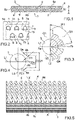
figure 1 is a plan view of a fin not forming part of the present invention; -
figure 2 is a view of a detail in enlarged scale of the fin offigure 1 ; -
figures 3 and 4 respectively illustrate a hole of a fin with indications of the area of installation of a baffle and a partially surrounded hole according to the embodiment offigure 1 ; -
figure 5 is a perspective view of a finned pack with a plurality of fins according tofigure 1 ; -
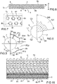
figures 6 to 10 are respectively views similar tofigures 1 to 5 with reference to another embodiment of a fin and finned pack not forming part of the present invention; -
figures 11 to 15 are respectively views similar tofigures 1 to 5 with reference to a further embodiment of a fin and finned pack in accordance with the present invention; -
figure 16 is a view of a finned pack according to the present invention and including a fin in accordance with the present invention; and -
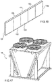
figures 17 to 19 are views of heat exchangers in which a finned pack according to the present invention can be installed. - In the set of drawings, equivalent parts or components are marked by the same reference numbers.
- With reference to
Figures 1 to 5 , a fin 1 for a finned pack for heat exchangers is illustrated, which comprises a plate 2 in which a plurality of throughholes 3 is made for the positioning of tubes 4 intended to convey a first heat exchange fluid, e.g. a liquid. - The plate 2 has an edge 5 as well as two
main faces 6 each intended to be licked or affected by a second heat exchange fluid, such as air, in a crossing direction A-A from aninlet portion 5a to an outlet portion 5b of the edge 5 of the plate 2. For such purpose, the facingmain faces 6 of two adjacent and successive fins 1 delimit, between them, a respective area of passage or crossing of a second fluid which hits respective sections of the tubes 4 engaged in such fins. - The edge 5 actually constitutes an external connection face between the two
main faces 6 and the same can be provided with two main sidesmain sides 5a, 5b, e.g. parallel, which are connected like a bridge by means of secondary orsmaller sides main sides 5a, 5b actually respectively constitute theinlet portion 5a and the outlet portion 5b. - The
holes 3 are delimited by a respective inner delimitingwall 7 of the plate 2, which includes afirst portion 7a facing towards theinlet portion 5a and asecond portion 7b facing towards the outlet portion 5b. The delimitingwall 7 of theholes 3 can be substantially cylindrical. - The fin 1 then comprises one or
more confinement units second portion 7b of thedelimiting wall 7 of ahole 3 of the plurality of holes so as to obtain or define a partially surrounded hole or better yet a respective partially surroundedhole 3. Preferably, aconfinement unit hole 3 of the fin 1 or in any case for most of theholes 3 of the fin itself. Still more preferably, the confinement units do not affect or better yet are not arranged around thefirst portion 7a of the respectivedelimiting wall 7. - More particularly, at least one confinement unit comprises two
first baffles hole 3, as well as each surrounding and spaced from a respective section of thesecond portion 7b of the delimitingwall 7 of the partially surroundedhole 3, so as to confine, during use, on the plate 2 a first flow zone FZ1 of the second fluid between eachbaffle 8 or recess and a respective section of thesecond portion 7b of the delimitingwall 7. - The configuration that will be described with reference to the first baffles is in substance also applied to the second baffles and vice versa, if it is considered that, once a finned pack is assembled, such components (first or second baffles) are intended to carry out the same task in substantially the same manner.
- The first flow zone FZ1 comprises an introduction mouth for the second fluid, delimited between the plate 2, the
first baffles delimiting wall 7 as well as a delivery mouth for the second fluid leading into an area downstream of therespective hole 3, i.e. an area subsequent to thehole 3 in the sense of the crossing direction A-A. The first flow zone FZ1 or better yet the walls thereof are fluid-tight so as to prevent leaks or exits of liquid between the introduction mouth and the delivery mouth. - With regard to the introduction mouth, this is preferably delimited between the plate 2, a
first end first baffles second portion 7b of thedelimiting wall 7. - Advantageously, the
first baffles 8 or the recesses can also be extended beyond a respective hole, i.e. have end sections closer to the outlet portion 5b with respect to a respective hole and hence define a second flow zone FZ2, which actually constitutes a continuation of the first flow zone FZ1, such second flow zone FZ2 being delimited between end sections of thefirst baffles - In such a manner, a confinement of the second fluid is obtained downstream of the partially surrounded
hole 3, with the expression confinement "downstream" indicating a confinement of the second fluid in the area or zone of the fin 1 that such fluid crosses after having affected thehole 3 or better yet hit the tube 4 engaged in thehole 3. - The second flow zone FZ2 has a feeding mouth corresponding to the delivery mouth of the first flow zone FZ1 as well as a mouth for discharging the second fluid towards subsequent holes or parts of the fin with reference to the crossing direction A-A. The second flow zone FZ2 or better yet the walls thereof are fluid-tight so as to prevent leaks or exits of fluid between the delivery mouth and the discharge mouth.
- Advantageously, the
holes 3 are each extended around a respective axis of symmetry x-x, with the axes of symmetry x-x of theholes 3 being substantially parallel to each other, while thefirst baffles confinement unit inlet portion 5a to an outlet portion 5b of the edge 5 and (passing) through the axis of symmetry x-x of the respective at least partially surroundedhole 3. - In addition, the
delimiting wall 7 can have acollar section 7c projecting upward with respect to one of themain faces 6, while thefirst baffles hole 3 withcollar section 7c are extended around at least one part of thecollar section 7c distal from theinlet portion 5a and facing towards the outlet portion 5b, the first or second baffles having height or thickness equal to or less than thecollar section 7c. Thecollar section 7c of the delimitingwalls 7 mainly carries out the function of spacer between two adjacent and successive fins 1 of a finned pack. - Advantageously, the
first baffles more confinement units first end inlet portion 5a as well as asecond end 8b, 9b distal from theinlet portion 5a of the plate 2. Theproximal ends first baffles distal ends 8b, 9b of thefirst baffles inlet portion 5a. In addition, in such case, preferably there are no intermediate sections of thefirst baffles proximal ends - If desired, the distance between the
first baffles 8 could initially decrease going away from theinlet portion 5a and then, once a minimum value is attained at an intermediate portion of the first baffles, once again increase up to thesecond end 8b, 9b, in which case the distance between the first baffles at the respectivesecond end 8b, 9b could also be greater than the distance D1. In such case, the area between the proximal ends and the intermediate portions of the first baffles or of the housing recesses is substantially tapered in the direction going away from theinlet portion 5a, while a second area would be provided between the intermediate portions and the second ends of the first baffles or of the housing recesses with an initial section with decreasing cross section and then an end section with increasing cross section going away from theinlet portion 5a. - In addition, the (first and/or second) baffles can have a flat or slightly curved laminar body with position, preferably, orthogonal or projecting upward with respect to the plate 2. In addition, the (first and/or second) baffles are, preferably, fluid-tight (if desired they are not perforated) so as to prevent the passage of the second fluid through them. In addition, each baffle is preferably formed in a single piece.
- If desired, the first baffles comprise a drawn portion, or sheared and bent portion of the plate 2, i.e. the
baffles collar section 7c is provided, then both thefirst baffles collar sections 7c are obtained by means of drawing of a respective plate 2. - Alternatively, the (first and/or second)
baffles confinement unit baffles - The height or thickness of the (first and/or second)
baffles - In addition, in order to define the position of the baffles, one or
more holes 3 with substantially circular cross section, and thefirst portion 7a and thesecond portion 7b with substantially semi-circular cross section, will be considered. - The following will also be defined in a plane transverse or orthogonal to the axis x-x: first straight line L1, that defined by the crossing direction A-A and passing through the axis of symmetry x-x, and second straight line L2, that orthogonal to the first straight line L1 and always passing through the axis of symmetry x-x.
- Quadrants will then be defined, which are always delimited in a plane transverse or orthogonal to the axis x-x, between the first L1 and the second L2 straight line and , more particularly, first Q1 and second Q2 quadrant are those defined between first L1 and second L2 straight line and enclosing a respective half or part of the
first portion 7a (or within which such portion lies), and third Q3 and fourth Q4 quadrant are those defined between first L1 and second L2 straight line and enclosing a respective half or part of thesecond portion 7b. - On the basis of the considerations and definitions provided up to now, the
baffles - In addition, each
baffle wall 7 and more particularly from a section of thesecond portion 7b of the delimitingwall 7 between about 1 mm and about 10 mm. - A fin like that illustrated in
figures 1 to 5 allows reducing the so-called "dead zone" downstream of the tubes, with reference to the direction A-A of the flow of the second fluid. - The
baffles second portion 7b of therespective delimiting wall 7 and then towards the respective tube 4, which ensures that each portion of the delimitingwall 7 and hence of the respective tube is affected by the second fluid. - With reference now to the embodiment illustrated in
figures 6 to 10 , thebaffles first section 81c, 91c surrounding and spaced from a respective section of thesecond portion 7b of the delimitingwall 7 of a partially surroundedhole 3 as well as asecond section - The
baffles -
Such baffles - On the basis of the considerations and definitions provided above, the
first section 81c, 91c of thebaffles - The
first section 81c, 91c can also be substantially straight or curved or, if desired, with multiple sections that are slightly tilted from one other, but each tilted at an angle between 0° and 80° with respect to the second straight line L2. - In addition, each
baffle first section 81c, 91c of eachbaffle wall 7 and more particularly from a part of thesecond portion 7b of the delimitingwall 7 between about 1 mm and about 15 mm. - The
second section holes 3, wherein by row ofholes 3 or tubes 4 it is intended the set of holes of a fin or of the tubes engaged therein at a same distance from theinlet portion 5a and by successive rows it is intended rows arranged one after the other in the sense of the crossing direction A-A and that thus, during use, are affected by the flow of the second fluid one after the other. - For such purpose, a fin according to the present invention preferably comprises two or more rows of
holes 3 offset with respect to one another with respect to the crossing direction A-A, such that each row ofholes 3 is at a different distance from theinlet portion 5a with respect to the other rows ofholes 3. - The thickness of a baffle, as now described, can vary between 0.1 and 5 mm.
- With reference now to the inventive embodiment illustrated in
figures 11 to 15 , a further embodiment is illustrated of a fin provided withbaffles first section 82c, 92c and asecond section reinforcement section 82e, 92e which is extended at the face of therespective baffle hole 3 and more particularly from an intermediate zone thereof to the free end of thesecond section inlet portion 5a. - According to the inventive embodiment, the
first section 82c, 92c is substantially rectilinear, while thesecond section reinforcement section 82e, 92e, an opening or first opening 11, e.g. with substantially triangular section, if desired extended substantially parallel to the axis of symmetry x-x of therespective hole 3. - Such opening 11 is typically used for the passage through the respective baffle, i.e. in direction substantially parallel to the axis x-x, of a third fluid such to increase the exchange efficiency of the exchanger or for complementary functions such as to the melting of frost in the case of operation of the exchanger as air heater. In addition, the opening 11 could also be fed with the first fluid.
- According to the invention the
baffles respective hole 3. With regard to thebaffles second section - The first opening 11 of one or more baffles could have a section with any suitable shape. e.g. circular, elliptical, rectangular or polygonal.
- In addition, two or more openings or micro-channels 11 could also be provided in each baffle.
- Clearly, an opening 11 as indicated above can in particular be present if the baffles comprise metal sections obtained - via extrusion, molding or shaping - separately with respect to the plates 2 and hence mechanically inserted in the plates 2 themselves.
- Due to
such baffles figures 11 to 15 is capable of making the respective finned pack self-supporting, increasing the heat exchange and increasing the speed of the fluid and the "primary" surface adapted to contain or delimit the passage of the second fluid. - The
baffles - Each
baffle wall 7 and more particularly from a section of thesecond portion 7b of the delimitingwall 7 between about 1 mm and about 15 mm. - Each
baffle - The first flow zone FZ1 between each
baffle second portion 7b can vary between 5 mm2 and the value of the passage section of the tube for the passage of the primary fluid or first fluid. - The thickness of a
baffle - With reference now in particular to the geometry and distribution of the holes in a fin, the following will be defined:
- the line or row of
holes 3 or of tubes 4 is the set of holes of a fin or of the tubes engaged therein at a same distance from theinlet portion 5a; - A is the pitch or distance of the
holes 3 or tubes 4 of a same row of tubes times the number of tubes of such row; and - B is the pitch or distance of the lines times the number of lines.
- Based on such definitions, a fin could have AxB between 10×10 and 100×100.
- Hereinbelow, the table reports several possible geometries and sizes for a fin as well as for the tubes to be engaged therein.
Geometry AxB C D Pitch of fins (mm) φ tube (mm) Arrangement of tubes or holes 25x21.65 11 6.25 1.6-3.6 7.2 Offset 25x21.65 11 6.25 1.6-3.6 7.94 Offset 25x21.65 11 6.25 1.6-5 9.52 Offset 25x25 12.5 12.5 1.6-3.5 9.52 Squared pitch 25x50 25 12.5 1.6-3.2 9.52 Squared pitch 30x26 13 12.5 1.6-5 9.52 Offset 30x26 13 12.5 1.6-5 12 Offset 37.5x32.5 16.25 9.37 4-8 9.52 Offset 37.5x32.5 16.25 9.37 1.6-8 12 Offset 50x25 25 25 2.5-12 12 Offset 50x25 25 25 2.5-12 15.88 Offset 50x25 25 25 2.5-12 12 Squared pitch 50x25 25 25 2.5-12 15.88 Squared pitch 50x50 25 25 2.5-12 12 Squared pitch 50x50 25 25 2.5-12 15.88 Squared pitch 50x50 25 25 2.5-12 12 Offset 50x50 25 25 2.5-12 15.88 Offset 30x30 15 15 1.8-7 15.88 Squared pitch 30x30 15 15 1.8-7 15.88 Offset 60x30 15 15 1.8-7 15.88 Squared pitch 60x30 15 15 1.8-7 15.88 Offset 60x60 15 15 1.8-7 15.88 Squared pitch 60x60 15 15 1.8-7 15.88 Offset - For such purpose, by C and D it is intended the distances between the holes at the edges of the plate 2 and the sides of the edge of the respective plate 2. The above-reported values for C and D are naturally merely given for exemplifying purposes.
- In addition, a fin could also have AxB equal to 48x41.75 or 50x40 with tubes of diameter equal to 12mm or 16 mm, or AxB equal to 20x20 with tubes having 5 mm diameter.
- With regard instead to the definition of "offset" of the tubes or holes: it is intended that the holes of adjacent and successive rows are offset with reference to the crossing direction A-A, while the definition "squared pitch" indicates that the holes or the tubes of adjacent and successive rows are aligned, always with reference to the crossing direction A-A. For such purpose, in a fin each row of
holes 3 comprises at least one hole aligned along the crossing direction A-A with a respective hole of the other rows of holes and/or at least one hole offset with respect to theholes 3 of the other rows ofholes 3, always with reference to the crossing direction A-A. - In substance, a fin comprises two or more lines or rows of
holes 3, i.e. groups of holes substantially at a same distance from theinlet portion 5a. In addition, the holes of adjacent and successive rows can be offset or aligned with reference to the crossing direction A-A. - In addition, in a fin holes for the positioning of heating elements could also be provided (or not provided), e.g. through holes with diameter equal to 9.5 mm.
- The thickness of a fin can vary between 0.1 mm and 0.4 mm.
- The pitch or distance between the fins can vary between 1.2 and 12 mm.
- A fin 1 can then have a smooth surface or so-called "w_vaffle", "pyramid" or "turbulent" surface. Such fin can also have a so-called "jagged" or "smooth" edge.
- The fin 1 could be made of any suitable material, e.g. aluminum, aluminum alloys, copper, copper alloys, steel, stainless steel in different alloys, such as AISI 304, AISI 316, etc..
- In addition, the fin 1 could be finished with surface treatments, e.g. varnishing, cataphoresis or other treatments.
- With reference now to
figure 16 , afinned pack 10 according to the present invention for heat exchangers is illustrated, which comprises a plurality of fins 1 according to the present invention, arranged in succession one after the other or one next to the other and substantially parallel to each other. Each fin 1 also has its throughholes 3 aligned with the throughholes 3 of the other fins 1. - The finned
pack 10 then comprises anintroduction opening 10a for a second fluid between pairs of fins of the plurality of fins, and anoutlet opening 10b for the second fluid between the pairs of fins. The fins 1 have theirinlet portions 5a at the introduction opening 10a and their outlet portions 5b at the outlet opening 5b. - A plurality of tubes 4 inserted in the aligned through holes of the plurality of fins 1 are also provided in the exchanger, the tubes 4 having a first sector 4a facing towards the
inlet opening 10a as well as asecond sector 4b facing towards theoutlet opening 10b, the fins 1 having the confinement unit orunits - As already stated above, the facing
main faces 6 of two adjacent and successive fins 1 delimit, between them, a respective area of passage or crossing of a second fluid which hits respective sections of the tubes 4 engaged in such fins, and such tubes 4 along with the baffles are extended through the passage areas so as to be hit by the flow of the second fluid. - The finned
pack 10 can then comprise anupper tile 10c, alower tile 10d and, additionally, at one side manifolds 10f for the tubes 4 and on the other sidesmall forks 10g for sending the first fluid between two tubes 4. - If desired, each fin has at least one confinement unit with two through recesses for positioning baffles and each through recess of each confinement unit is aligned with a respective recess of the other fins. In such case, the finned pack also comprises two baffles for each confinement unit, each inserted in a respective series of aligned through recesses of the fins 1, preferably of all the fins of the finned
pack 10. - According to such variant, the baffles or bars could constitute a load-bearing mechanical element of the finned
pack 10. This is particularly applied to the embodiments illustrated infigures 6 to 15 . - In addition, if the baffles delimit an opening 11, the finned
pack 10 or better yet the respective heat exchanger could comprise means for feeding a third fluid or the first fluid into the opening 11 of one ormore baffles baffles - The tubes 4 of a
finned pack 10 could for example be made of copper and alloys thereof, stainless steel and alloys thereof, iron and alloys thereof, aluminum and alloys thereof or other suitable materials. - The tubes could also have an internal wall that is smooth, or grooved, e.g. tilted groove, helical grooved or grooved with crossed spirals.
- The tubes could then have a diameter between 4 and 35 mm, advantageously between 5 and 22 mm, preferably 5 mm, 6.35 mm, 7.2 mm, 7.9 mm, 9.5 mm, 12 mm, 14, 16 mm or 22 mm.
- The thickness of the tubes instead preferably varies between 0.15 and 1.50 mm, and, still more preferably, it is equal to 0.25 mm, 0.28 mm, 0.32 mm, 0.35 mm, 0.4 mm or 0.5 mm.
- A finned pack according to the present invention can be integrated or installed in:
- a fluid condenser or cooler 13 (see
figure 17 ), i.e. a machine intended for the heat exchange between a coolant fluid to be cooled and the environment, which can employ liquid, aeriform or gaseous coolant fluids; - in a gas cooler 14 (see
figure 18 ), e.g. with CO2, which is a cooler intended for the heat exchange between a coolant fluid, such as CO2 to be cooled, and the environment; or - in a dry cooler 15 (see
figure 19 ), it too intended for the heat exchange between a coolant fluid to be cooled and the environment which can employ liquid, aeriform or gaseous coolant fluids. - an air evaporator or air cooler, i.e. a machine intended for the heat exchange between a coolant fluid being evaporated/heating and a secondary fluid to be cooled, which can employ liquid, two-phase or gaseous coolant fluids;
- As will be understood, a fin and a finned pack according to the present invention allow conveying the second fluid around the entire surface of the holes and hence of the tubes of the fin, also in the zone of each tube that faces towards the outlet portion.
- For such purpose, in fact, the applicants of the present patent application have been able to establish that with fins and finned packs according to the state of the art, the second fluid correctly and uniformly hits and affects the part of the tubes facing towards the inlet portion of the fins, but in the zone between the tubes of one row and the tubes of a subsequent row, the second fluid is "detached" from the external surface of the tubes, hence not affecting that part of the tubes facing towards the outlet portion of the fins. Naturally, this involves a considerable reduction of the heat exchange efficiency, since most of the external face of the tubes crossed by the first fluid is not in heat exchange contact with the second fluid.
- Due to the confinement units of a fin according to the present invention and of a respective finned pack, the second fluid is instead in fact guided and maintained next to the tubes, even in the zone downstream thereof, so as to affect the second fluid and place it in heat exchange with the entire external face of the tubes, considerably improving the obtainable heat exchange efficiency.
- Modifications and variants of the invention are possible provided they come within the protective scope defined by the claims.
Claims (23)
- Fin (1) for a finned pack (10) for heat exchangers, comprising a plate (2) in which a plurality of through holes (3) is made for the positioning of tubes (4) intended to convey a first heat exchange fluid, said plate (2) having an edge (5) as well as two main faces (6) each intended to be licked by a second heat exchange fluid in a crossing direction (A-A) from an inlet portion (5a) to an outlet portion (5b) of said edge (5) of said plate (2), said holes (3) being delimited by a respective inner delimiting wall (7) of said plate (2) including a first portion (7a) facing towards said inlet portion (5a) and a second portion (7b) facing towards said outlet portion (5b), said fin comprising at least one confinement unit (8, 81, 82, 9, 91, 92) for said second fluid arranged around a hole (3) of said plurality of holes (3) so as to obtain at least one partially surrounded hole (3), said at least one confinement unit comprising two baffles (8, 81, 82, 9, 91, 92) arranged one opposite the other with respect to a respective partially surrounded hole (3) as well as each surrounding and spaced from a respective section of said second portion (7b) of said delimiting wall (7) of said partially surrounded hole (3), so as to confine, during use, on said plate (2) a first flow zone (FZ1) of said second fluid between each baffle (8, 81, 82, 9, 91, 92) and a respective section of said second portion (7b) of said delimiting wall (7), characterized in that said baffles (8, 9, 81, 91, 82, 92) have a substantially tubular structure so as to delimit a first opening (11).
- Fin (1) according to claim 1, wherein the baffles (8, 81, 82, 9, 91, 92) of a respective confinement unit have a first end (8a, 9a) proximal to said inlet portion (5a), a second end (8b, 9b) distal from said inlet portion (5a) of said plate (2) as well as an intermediate portion between said first (8a, 9a) and said second (8b, 9b) end;- said first ends (8a, 9a) being at a first distance (D1) from each other, while said second ends (8b, 9b) or said intermediate portion are at a second distance (D2) from each other that is less than said first distance (D1), such that the baffles (8, 81, 82, 9, 91, 92) delimit between them at least one first area substantially tapered in the direction going away from said inlet portion (5a).
- Fin (1) according to claim 1 or 2, wherein said first flow zone (FZ1) comprises an introduction mouth for the second fluid, delimited between said plate (2), said baffles (8, 81, 82, 9, 91, 92) and a part of said delimiting wall (7) as well as a delivery mouth for the second fluid leading into an area of said plate (2) subsequent to said hole (3) in the direction of said crossing direction (A-A).
- Fin (1) according to any one of the claims 1, 2 or 3, wherein said baffles (8, 81, 82, 9, 91, 92) are extended beyond a respective partially surrounded hole (3), i.e. that said baffles (8, 81, 82, 9, 91, 92) have end sections closer to said outlet portion (5b) with respect to a respective partially surrounded hole (3) and defining a second flow zone (FZ2) constituting a continuation of said first flow zone (FZ1), said second flow zone (FZ2) having a feeding mouth corresponding to said delivery mouth of said first flow zone (FZ1) as well as a discharge mouth of said second fluid towards parts of said fin that follow in the sense of said crossing direction (A-A).
- Fin (1) according to any one of the preceding claims, wherein each one of said holes (3) of said plurality of holes extended around a respective axis of symmetry (x-x), the axes of symmetry (x-x) of said holes (3) being substantially parallel to each other, and wherein said baffles (8, 81, 82, 9, 91, 92) are substantially symmetrical to one another with respect to a plane passing through said crossing direction (A-A) and through the axis of symmetry (x-x) of the respective at least partially surrounded hole (3).
- Fin (1) according to any one of the preceding claims, wherein said delimiting wall (7) of at least one partially surrounded hole (3) has a collar section (7c) projecting upward with respect to one of said main faces (6), while the baffles (8, 81, 82, 9, 91, 92) surrounding said partially surrounded hole (3) with collar section (7c) are extended around at least one part of said collar section (7c) distal from said inlet portion (5a) and facing towards said outlet portion (5b), said baffles (8, 81, 82, 9, 91, 92) having height or thickness equal to or less than said collar section (7c).
- Fin (1) according to any one of the preceding claims, wherein said baffles (8, 81, 82, 9, 91, 92) comprise a drawn portion of said plate (2).
- Fin (1) according to any one of the preceding claims, wherein said baffles (8, 81, 82, 9, 91, 92) comprise a flat or slightly curved laminar body with position orthogonal or projecting upward with respect to said plate (2).
- Fin (1) according to claim 8, wherein said second baffles (8, 81, 82, 9, 91, 92) comprise metal sections obtained via extrusion, molding or shaping and then inserted in said plate (2).
- Fin (1) according to any one of the preceding claims, wherein said baffles are fluid-tight, so as to prevent the passage of the second fluid through them.
- Fin (1) according to any one of the preceding claims, wherein at least one hole (3) of said plurality of holes has a substantially circular cross section, while said first portion (7a) and said second portion (7b) have substantially semi-circular cross section, and wherein said baffles (8, 9) of a confinement unit arranged around said at least one hole (3) with substantially circular cross section are positioned with one in a third quadrant (Q3) and the other in a fourth quadrant (Q4), and each of said baffles (8, 81, 81, 9, 91, 92) of a confinement unit is positioned in a circular-sector shaped area defined by a straight line coming out from said axis of symmetry (x-x) and tilted at a tilt angle (IA1, IA2, IA3) between 0° and 80°, between 10° and 80° or between 0° and 50° with respect to a second straight line (L2),wherein in a plane transverse or orthogonal to an axis of symmetry (x-x) of said hole (3) with substantially circular cross section, first straight line (L1) is defined as a straight line parallel to the crossing direction (A-A) and passing through said axis of symmetry (x-x) and second straight line (L2) is defined as the straight line orthogonal to said first straight line (L1) and passing through said axis of symmetry (x-x), andwherein quadrants (Q1, Q2, Q3, Q4) are those delimited, in a plane transverse or orthogonal to said axis of symmetry (x-x), between said first (L1) and said second (L2) straight line, and wherein a first (Q1) and a second (Q2) quadrant are defined between said first (L1) and said second straight line (L2) and enclose a respective half or part of said first portion (7a), while a third (Q3) and a fourth (Q4) quadrant are those defined between first (L1) and second straight line (L2) and enclosing a respective half or part of said second portion (7b).
- Fin (1) according to any one of the preceding claims, wherein each baffle (8, 9) is at a third distance (D3) from a section of said second portion (7b) of said delimiting wall (7) between about 1 mm and about 10 mm or each baffle (81, 91) is at a fourth distance (D4) from a part of said second portion (7b) of said delimiting wall (7) between about 1 mm and about 15 mm.
- Fin (1) according to any one of the preceding claims, wherein said baffles (81, 91) have a first section (81c, 91c) surrounding and spaced from a respective section of the second portion (7b) of the delimiting wall (7) of a partially surrounded hole (3) as well as a second section (81d, 91d) projecting upward from said first section (8c) and for example substantially parallel to said crossing direction (A-A).
- Fin (1) according to claims 11 and 13, wherein said first section (81c, 91c) is curved or has multiple sections that are slightly tilted from one another, but each tilted at an angle between 0° and 80° with respect to said second straight line (L2).
- Fin (1) according to any one of the preceding claims, wherein said baffles (82, 92) have a first section (82c, 92c), a second section (82d, 92d) as well as a reinforcement section (82e, 92e) which is extended at the face of the respective baffle (82, 92) facing away from the respective partially surrounded hole (3) and is extended from an intermediate zone of said first section (82c, 92c) to the free end of said second section (82d, 92d).
- Fin (1) according to any one of the preceding claims when dependent on claim 5, wherein said first opening (11) is extended substantially parallel to the axis of symmetry (x-x) of the respective hole (3) and is set to allow the passage through the respective baffle and in a direction substantially parallel to said axis of symmetry (x-x) of a third fluid or of said first fluid.
- Fin (1) according to claims 15, wherein said first opening (11) is defined between said second section (82d, 92d) and said reinforcement section (82e, 92e).
- Fin according to any one of the preceding claims, wherein said plurality of through holes (3) comprises two or more rows of holes (3) offset with respect to one another at said crossing direction (A-A), such that each row of holes (3) is at a different distance from said inlet portion (5a) with respect to the other rows of holes (3), and wherein each row of holes (3) comprises at least one hole (3) aligned along said crossing direction (A-A) with a respective hole (3) of the other rows of holes (3) and/or at least one hole (3) offset with respect to the holes (3) of the other rows of holes (3) with reference to said crossing direction (A-A).
- Finned pack (10) for a heat exchanger, comprising:- a plurality of fins (1) according to any one of the preceding claims arranged one after the other in succession and substantially parallel to each other, each fin (1) having its through holes (3) aligned with the through holes (3) of the other fins (1);- an introduction opening (10a) for a second fluid between pairs of fins (1) of said plurality of fins (1), said fins (1) having their inlet portions (5a) at said introduction opening (10a);- an outlet opening (10b) of said second fluid between said pairs of fins (1), said fins (1) having their outlet portions (5b) at said outlet opening (10b);- a plurality of tubes (4) engaged in the aligned through holes (3) of said plurality of fins (1), said tubes (4) having a first sector (4a) facing towards said inlet opening (10a) as well as a second sector (4b) facing towards said outlet opening (10b); andsaid fins (1) having a confinement unit (8, 81, 82, 9, 91, 92) around a portion of a second sector (4b) of at least one of said tubes (4).
- Finned pack (10) for a heat exchanger, comprising a plurality of fins (1) arranged one after the other in succession and substantially parallel to each other, each fin (1) having its through holes (3) aligned with the through holes (3) of the other fins (1),each fin (1) comprising a plate (2) in which a plurality of through holes (3) is made for the positioning of tubes (4) intended to convey a first heat exchange fluid, said plate (2) having an edge (5) as well as two main faces (6) each intended to be licked by a second heat exchange fluid in a crossing direction (A-A) from an inlet portion (5a) to an outlet portion (5b) of said edge (5) of said plate (2), said holes (3) being delimited by a respective inner delimiting wall (7) of said plate (2) including a first portion (7a) facing towards said inlet portion (5a) and a second portion (7b) facing towards said outlet portion (5b), said fin comprising at least one confinement unit (8, 81, 82, 9, 91, 92) for said second fluid arranged around a hole (3) of said plurality of holes (3) so as to obtain at least one partially surrounded hole (3), said at least one confinement unit comprising two through housing recesses for housing second baffles arranged one opposite the other with respect to a respective partially surrounded hole (3) as well as each surrounding and spaced from a respective section of said second portion (7b) of said delimiting wall (7) of said partially surrounded hole (3), so as to confine, during use, on said plate (2) a first flow zone (FZ1) of said second fluid between each recess and a respective section of said second portion (7b) of said delimiting wall (7),said finned pack further comprising:- an introduction opening (10a) for a second fluid between pairs of fins (1) of said plurality of fins (1), said fins (1) having their inlet portions (5a) at said introduction opening (10a);- an outlet opening (10b) of said second fluid between said pairs of fins (1), said fins (1) having their outlet portions (5b) at said outlet opening (10b);- a plurality of tubes (4) engaged in the aligned through holes (3) of said plurality of fins (1), said tubes (4) having a first sector (4a) facing towards said inlet opening (10a) as well as a second sector (4b) facing towards said outlet opening (10b),wherein said fins (1) having a confinement unit (8, 81, 82, 9, 91, 92) around a portion of a second sector (4b) of at least one of said tubes (4),wherein each through housing recess of each confinement unit is aligned with a respective housing recess of the other fins (1), and wherein said finned pack (10) also comprises at least two second baffles, each second baffle being inserted in a respective series of aligned through recesses of said fins (1), andwherein said second baffles have a substantially tubular structure so as to delimit a first opening (11).
- Heat exchanger with finned pack comprising at least one finned pack according to claim 19 or 20.
- Heat exchanger according to claim 21 when comprising fins according to claim 1 to 18, comprising means for feeding a third fluid or the first fluid in said first opening (11) of one or more baffles (8, 9, 81, 91, 82, 92).
- Process for obtaining a fin (1) according to claim 7, comprising a step of arranging said plate (2) and then a step of drawing for obtaining said baffles (8, 81, 82, 9,91,92).
Applications Claiming Priority (2)
| Application Number | Priority Date | Filing Date | Title |
|---|---|---|---|
| ITVR20140284 | 2014-11-14 | ||
| PCT/IB2015/058784 WO2016075666A1 (en) | 2014-11-14 | 2015-11-13 | Fin for a finned pack for heat exchangers, as well as heat exchanger |
Publications (2)
| Publication Number | Publication Date |
|---|---|
| EP3218664A1 EP3218664A1 (en) | 2017-09-20 |
| EP3218664B1 true EP3218664B1 (en) | 2022-06-01 |
Family
ID=52355116
Family Applications (1)
| Application Number | Title | Priority Date | Filing Date |
|---|---|---|---|
| EP15818036.4A Active EP3218664B1 (en) | 2014-11-14 | 2015-11-13 | Fin for a finned pack for heat exchangers, as well as heat exchanger |
Country Status (4)
| Country | Link |
|---|---|
| US (1) | US10948244B2 (en) |
| EP (1) | EP3218664B1 (en) |
| CN (1) | CN107223198B (en) |
| WO (1) | WO2016075666A1 (en) |
Families Citing this family (3)
| Publication number | Priority date | Publication date | Assignee | Title |
|---|---|---|---|---|
| US11781812B2 (en) | 2016-08-31 | 2023-10-10 | Brazeway, Inc. | Fin enhancements for low Reynolds number airflow |
| US10578374B2 (en) | 2016-08-31 | 2020-03-03 | Brazeway, Inc. | Fin enhancements for low Reynolds number airflow |
| US11499747B2 (en) * | 2019-10-04 | 2022-11-15 | Rheem Manufacturing Company | Heat exchanger tubes and tube assembly configurations |
Citations (5)
| Publication number | Priority date | Publication date | Assignee | Title |
|---|---|---|---|---|
| US20040194936A1 (en) * | 2001-08-10 | 2004-10-07 | Kahoru Torii | Heat transfer device |
| EP2072939A1 (en) * | 2006-10-02 | 2009-06-24 | Daikin Industries, Ltd. | Fin tube type heat exchanger |
| WO2011082922A1 (en) * | 2009-12-16 | 2011-07-14 | Behr Gmbh & Co. Kg | Heat exchanger |
| CN102135388A (en) * | 2011-03-25 | 2011-07-27 | 兰州交通大学 | Triangular curved vortex generator type circular tube fin heat exchanger |
| WO2014104576A1 (en) * | 2012-12-26 | 2014-07-03 | 주식회사 경동나비엔 | Pin-tube type heat exchanger |
Family Cites Families (11)
| Publication number | Priority date | Publication date | Assignee | Title |
|---|---|---|---|---|
| US1775041A (en) * | 1925-02-21 | 1930-09-02 | Karmazin John | Radiator |
| DE496733C (en) * | 1928-10-27 | 1930-04-24 | E H Hugo Junkers Dr Ing | Finned tube heat exchange device with ribs made from sheet metal of the same thickness everywhere |
| JPS61110889A (en) * | 1984-11-05 | 1986-05-29 | Matsushita Electric Ind Co Ltd | Finned heat exchanger |
| US4787442A (en) * | 1987-12-04 | 1988-11-29 | Carrier Corporation | Delta wing and ramp wing enhanced plate fin |
| JPH0375498A (en) * | 1989-08-18 | 1991-03-29 | Matsushita Refrig Co Ltd | Fine tube type heat exchanger |
| US4984626A (en) * | 1989-11-24 | 1991-01-15 | Carrier Corporation | Embossed vortex generator enhanced plate fin |
| US6578627B1 (en) * | 2001-12-28 | 2003-06-17 | Industrial Technology Research Institute | Pattern with ribbed vortex generator |
| US20040200608A1 (en) * | 2003-04-11 | 2004-10-14 | Baldassarre Gregg J. | Plate fins with vanes for redirecting airflow |
| JP4982870B2 (en) * | 2005-12-28 | 2012-07-25 | 国立大学法人横浜国立大学 | Heat transfer device |
| CN101523148A (en) * | 2006-10-02 | 2009-09-02 | 大金工业株式会社 | Fin tube type heat exchanger |
| CN201106998Y (en) * | 2007-09-29 | 2008-08-27 | 株洲通达铁路电机厂 | Radiation core for diesel engine intercooler |
-
2015
- 2015-11-13 WO PCT/IB2015/058784 patent/WO2016075666A1/en not_active Ceased
- 2015-11-13 CN CN201580064928.9A patent/CN107223198B/en active Active
- 2015-11-13 EP EP15818036.4A patent/EP3218664B1/en active Active
- 2015-11-13 US US15/526,198 patent/US10948244B2/en active Active
Patent Citations (5)
| Publication number | Priority date | Publication date | Assignee | Title |
|---|---|---|---|---|
| US20040194936A1 (en) * | 2001-08-10 | 2004-10-07 | Kahoru Torii | Heat transfer device |
| EP2072939A1 (en) * | 2006-10-02 | 2009-06-24 | Daikin Industries, Ltd. | Fin tube type heat exchanger |
| WO2011082922A1 (en) * | 2009-12-16 | 2011-07-14 | Behr Gmbh & Co. Kg | Heat exchanger |
| CN102135388A (en) * | 2011-03-25 | 2011-07-27 | 兰州交通大学 | Triangular curved vortex generator type circular tube fin heat exchanger |
| WO2014104576A1 (en) * | 2012-12-26 | 2014-07-03 | 주식회사 경동나비엔 | Pin-tube type heat exchanger |
Also Published As
| Publication number | Publication date |
|---|---|
| US20170321969A1 (en) | 2017-11-09 |
| EP3218664A1 (en) | 2017-09-20 |
| US10948244B2 (en) | 2021-03-16 |
| WO2016075666A1 (en) | 2016-05-19 |
| CN107223198A (en) | 2017-09-29 |
| CN107223198B (en) | 2020-07-17 |
Similar Documents
| Publication | Publication Date | Title |
|---|---|---|
| US8459342B2 (en) | Heat exchanger tube with integral restricting and turbulating structure | |
| US8656986B2 (en) | Fin, heat exchanger and heat exchanger assembly | |
| KR950007282B1 (en) | Capacitors with subdivided flow paths | |
| US20170108279A1 (en) | Heat exchanger with multiple flow tubes for fluid circulation | |
| US10753687B2 (en) | Heat exchanger tube | |
| EP3370019B1 (en) | Heat exchanger | |
| WO2013150818A1 (en) | Heat transfer tube, and heat exchanger using same | |
| US20130299132A1 (en) | Heat exchanger assembly and method of manufacturing therefor | |
| US12320550B2 (en) | Heat-exchange pipe, heat-exchanger unit using same, and condensing boiler using same | |
| US20130240177A1 (en) | Nested heat exchanger | |
| US10948244B2 (en) | Fin for a finned pack for heat exchangers, as well as heat exchanger | |
| US20070169922A1 (en) | Microchannel, flat tube heat exchanger with bent tube configuration | |
| US20190145716A1 (en) | Fin for a finned pack for heat exchangers as well as a heat exchanger | |
| KR102025459B1 (en) | Tubing element for a heat exchanger means | |
| US10267565B1 (en) | Spiral heat exchanger coils | |
| KR102010156B1 (en) | shell in a shell and plate heat exchanger, and shell and plate heat exchanger having the same | |
| EP0654647A1 (en) | A finned tube for a heat exchanger device | |
| KR100530268B1 (en) | Shell and tube type heat exchanger | |
| EP3027996B1 (en) | Fired heat exchanger pipe | |
| EP2926072B1 (en) | Tubing element for heat exchanger means | |
| EP3526536B1 (en) | Flame pipe of a fired heat exchanger |
Legal Events
| Date | Code | Title | Description |
|---|---|---|---|
| STAA | Information on the status of an ep patent application or granted ep patent |
Free format text: STATUS: THE INTERNATIONAL PUBLICATION HAS BEEN MADE |
|
| PUAI | Public reference made under article 153(3) epc to a published international application that has entered the european phase |
Free format text: ORIGINAL CODE: 0009012 |
|
| STAA | Information on the status of an ep patent application or granted ep patent |
Free format text: STATUS: REQUEST FOR EXAMINATION WAS MADE |
|
| 17P | Request for examination filed |
Effective date: 20170609 |
|
| AK | Designated contracting states |
Kind code of ref document: A1 Designated state(s): AL AT BE BG CH CY CZ DE DK EE ES FI FR GB GR HR HU IE IS IT LI LT LU LV MC MK MT NL NO PL PT RO RS SE SI SK SM TR |
|
| AX | Request for extension of the european patent |
Extension state: BA ME |
|
| DAV | Request for validation of the european patent (deleted) | ||
| DAX | Request for extension of the european patent (deleted) | ||
| STAA | Information on the status of an ep patent application or granted ep patent |
Free format text: STATUS: EXAMINATION IS IN PROGRESS |
|
| 17Q | First examination report despatched |
Effective date: 20200901 |
|
| GRAP | Despatch of communication of intention to grant a patent |
Free format text: ORIGINAL CODE: EPIDOSNIGR1 |
|
| STAA | Information on the status of an ep patent application or granted ep patent |
Free format text: STATUS: GRANT OF PATENT IS INTENDED |
|
| INTG | Intention to grant announced |
Effective date: 20211213 |
|
| GRAS | Grant fee paid |
Free format text: ORIGINAL CODE: EPIDOSNIGR3 |
|
| GRAA | (expected) grant |
Free format text: ORIGINAL CODE: 0009210 |
|
| STAA | Information on the status of an ep patent application or granted ep patent |
Free format text: STATUS: THE PATENT HAS BEEN GRANTED |
|
| AK | Designated contracting states |
Kind code of ref document: B1 Designated state(s): AL AT BE BG CH CY CZ DE DK EE ES FI FR GB GR HR HU IE IS IT LI LT LU LV MC MK MT NL NO PL PT RO RS SE SI SK SM TR |
|
| REG | Reference to a national code |
Ref country code: GB Ref legal event code: FG4D |
|
| REG | Reference to a national code |
Ref country code: AT Ref legal event code: REF Ref document number: 1495639 Country of ref document: AT Kind code of ref document: T Effective date: 20220615 Ref country code: CH Ref legal event code: EP Ref country code: DE Ref legal event code: R096 Ref document number: 602015079273 Country of ref document: DE |
|
| REG | Reference to a national code |
Ref country code: IE Ref legal event code: FG4D |
|
| REG | Reference to a national code |
Ref country code: LT Ref legal event code: MG9D |
|
| REG | Reference to a national code |
Ref country code: NL Ref legal event code: MP Effective date: 20220601 |
|
| PG25 | Lapsed in a contracting state [announced via postgrant information from national office to epo] |
Ref country code: SE Free format text: LAPSE BECAUSE OF FAILURE TO SUBMIT A TRANSLATION OF THE DESCRIPTION OR TO PAY THE FEE WITHIN THE PRESCRIBED TIME-LIMIT Effective date: 20220601 Ref country code: NO Free format text: LAPSE BECAUSE OF FAILURE TO SUBMIT A TRANSLATION OF THE DESCRIPTION OR TO PAY THE FEE WITHIN THE PRESCRIBED TIME-LIMIT Effective date: 20220901 Ref country code: LT Free format text: LAPSE BECAUSE OF FAILURE TO SUBMIT A TRANSLATION OF THE DESCRIPTION OR TO PAY THE FEE WITHIN THE PRESCRIBED TIME-LIMIT Effective date: 20220601 Ref country code: HR Free format text: LAPSE BECAUSE OF FAILURE TO SUBMIT A TRANSLATION OF THE DESCRIPTION OR TO PAY THE FEE WITHIN THE PRESCRIBED TIME-LIMIT Effective date: 20220601 Ref country code: GR Free format text: LAPSE BECAUSE OF FAILURE TO SUBMIT A TRANSLATION OF THE DESCRIPTION OR TO PAY THE FEE WITHIN THE PRESCRIBED TIME-LIMIT Effective date: 20220902 Ref country code: FI Free format text: LAPSE BECAUSE OF FAILURE TO SUBMIT A TRANSLATION OF THE DESCRIPTION OR TO PAY THE FEE WITHIN THE PRESCRIBED TIME-LIMIT Effective date: 20220601 Ref country code: ES Free format text: LAPSE BECAUSE OF FAILURE TO SUBMIT A TRANSLATION OF THE DESCRIPTION OR TO PAY THE FEE WITHIN THE PRESCRIBED TIME-LIMIT Effective date: 20220601 Ref country code: BG Free format text: LAPSE BECAUSE OF FAILURE TO SUBMIT A TRANSLATION OF THE DESCRIPTION OR TO PAY THE FEE WITHIN THE PRESCRIBED TIME-LIMIT Effective date: 20220901 |
|
| REG | Reference to a national code |
Ref country code: AT Ref legal event code: MK05 Ref document number: 1495639 Country of ref document: AT Kind code of ref document: T Effective date: 20220601 |
|
| REG | Reference to a national code |
Ref country code: FR Ref legal event code: PLFP Year of fee payment: 8 |
|
| PG25 | Lapsed in a contracting state [announced via postgrant information from national office to epo] |
Ref country code: RS Free format text: LAPSE BECAUSE OF FAILURE TO SUBMIT A TRANSLATION OF THE DESCRIPTION OR TO PAY THE FEE WITHIN THE PRESCRIBED TIME-LIMIT Effective date: 20220601 Ref country code: PL Free format text: LAPSE BECAUSE OF FAILURE TO SUBMIT A TRANSLATION OF THE DESCRIPTION OR TO PAY THE FEE WITHIN THE PRESCRIBED TIME-LIMIT Effective date: 20220601 Ref country code: LV Free format text: LAPSE BECAUSE OF FAILURE TO SUBMIT A TRANSLATION OF THE DESCRIPTION OR TO PAY THE FEE WITHIN THE PRESCRIBED TIME-LIMIT Effective date: 20220601 |
|
| PG25 | Lapsed in a contracting state [announced via postgrant information from national office to epo] |
Ref country code: NL Free format text: LAPSE BECAUSE OF FAILURE TO SUBMIT A TRANSLATION OF THE DESCRIPTION OR TO PAY THE FEE WITHIN THE PRESCRIBED TIME-LIMIT Effective date: 20220601 |
|
| PG25 | Lapsed in a contracting state [announced via postgrant information from national office to epo] |
Ref country code: SM Free format text: LAPSE BECAUSE OF FAILURE TO SUBMIT A TRANSLATION OF THE DESCRIPTION OR TO PAY THE FEE WITHIN THE PRESCRIBED TIME-LIMIT Effective date: 20220601 Ref country code: SK Free format text: LAPSE BECAUSE OF FAILURE TO SUBMIT A TRANSLATION OF THE DESCRIPTION OR TO PAY THE FEE WITHIN THE PRESCRIBED TIME-LIMIT Effective date: 20220601 Ref country code: RO Free format text: LAPSE BECAUSE OF FAILURE TO SUBMIT A TRANSLATION OF THE DESCRIPTION OR TO PAY THE FEE WITHIN THE PRESCRIBED TIME-LIMIT Effective date: 20220601 Ref country code: PT Free format text: LAPSE BECAUSE OF FAILURE TO SUBMIT A TRANSLATION OF THE DESCRIPTION OR TO PAY THE FEE WITHIN THE PRESCRIBED TIME-LIMIT Effective date: 20221003 Ref country code: EE Free format text: LAPSE BECAUSE OF FAILURE TO SUBMIT A TRANSLATION OF THE DESCRIPTION OR TO PAY THE FEE WITHIN THE PRESCRIBED TIME-LIMIT Effective date: 20220601 Ref country code: CZ Free format text: LAPSE BECAUSE OF FAILURE TO SUBMIT A TRANSLATION OF THE DESCRIPTION OR TO PAY THE FEE WITHIN THE PRESCRIBED TIME-LIMIT Effective date: 20220601 Ref country code: AT Free format text: LAPSE BECAUSE OF FAILURE TO SUBMIT A TRANSLATION OF THE DESCRIPTION OR TO PAY THE FEE WITHIN THE PRESCRIBED TIME-LIMIT Effective date: 20220601 |
|
| PG25 | Lapsed in a contracting state [announced via postgrant information from national office to epo] |
Ref country code: IS Free format text: LAPSE BECAUSE OF FAILURE TO SUBMIT A TRANSLATION OF THE DESCRIPTION OR TO PAY THE FEE WITHIN THE PRESCRIBED TIME-LIMIT Effective date: 20221001 |
|
| REG | Reference to a national code |
Ref country code: DE Ref legal event code: R097 Ref document number: 602015079273 Country of ref document: DE |
|
| PG25 | Lapsed in a contracting state [announced via postgrant information from national office to epo] |
Ref country code: AL Free format text: LAPSE BECAUSE OF FAILURE TO SUBMIT A TRANSLATION OF THE DESCRIPTION OR TO PAY THE FEE WITHIN THE PRESCRIBED TIME-LIMIT Effective date: 20220601 |
|
| PLBE | No opposition filed within time limit |
Free format text: ORIGINAL CODE: 0009261 |
|
| STAA | Information on the status of an ep patent application or granted ep patent |
Free format text: STATUS: NO OPPOSITION FILED WITHIN TIME LIMIT |
|
| PG25 | Lapsed in a contracting state [announced via postgrant information from national office to epo] |
Ref country code: DK Free format text: LAPSE BECAUSE OF FAILURE TO SUBMIT A TRANSLATION OF THE DESCRIPTION OR TO PAY THE FEE WITHIN THE PRESCRIBED TIME-LIMIT Effective date: 20220601 |
|
| 26N | No opposition filed |
Effective date: 20230302 |
|
| PG25 | Lapsed in a contracting state [announced via postgrant information from national office to epo] |
Ref country code: SI Free format text: LAPSE BECAUSE OF FAILURE TO SUBMIT A TRANSLATION OF THE DESCRIPTION OR TO PAY THE FEE WITHIN THE PRESCRIBED TIME-LIMIT Effective date: 20220601 |
|
| P01 | Opt-out of the competence of the unified patent court (upc) registered |
Effective date: 20230508 |
|
| PG25 | Lapsed in a contracting state [announced via postgrant information from national office to epo] |
Ref country code: MC Free format text: LAPSE BECAUSE OF FAILURE TO SUBMIT A TRANSLATION OF THE DESCRIPTION OR TO PAY THE FEE WITHIN THE PRESCRIBED TIME-LIMIT Effective date: 20220601 |
|
| REG | Reference to a national code |
Ref country code: CH Ref legal event code: PL |
|
| REG | Reference to a national code |
Ref country code: BE Ref legal event code: MM Effective date: 20221130 |
|
| PG25 | Lapsed in a contracting state [announced via postgrant information from national office to epo] |
Ref country code: LI Free format text: LAPSE BECAUSE OF NON-PAYMENT OF DUE FEES Effective date: 20221130 Ref country code: CH Free format text: LAPSE BECAUSE OF NON-PAYMENT OF DUE FEES Effective date: 20221130 |
|
| PG25 | Lapsed in a contracting state [announced via postgrant information from national office to epo] |
Ref country code: LU Free format text: LAPSE BECAUSE OF NON-PAYMENT OF DUE FEES Effective date: 20221113 |
|
| PG25 | Lapsed in a contracting state [announced via postgrant information from national office to epo] |
Ref country code: IE Free format text: LAPSE BECAUSE OF NON-PAYMENT OF DUE FEES Effective date: 20221113 |
|
| PG25 | Lapsed in a contracting state [announced via postgrant information from national office to epo] |
Ref country code: BE Free format text: LAPSE BECAUSE OF NON-PAYMENT OF DUE FEES Effective date: 20221130 |
|
| PG25 | Lapsed in a contracting state [announced via postgrant information from national office to epo] |
Ref country code: IT Free format text: LAPSE BECAUSE OF FAILURE TO SUBMIT A TRANSLATION OF THE DESCRIPTION OR TO PAY THE FEE WITHIN THE PRESCRIBED TIME-LIMIT Effective date: 20220601 |
|
| PG25 | Lapsed in a contracting state [announced via postgrant information from national office to epo] |
Ref country code: HU Free format text: LAPSE BECAUSE OF FAILURE TO SUBMIT A TRANSLATION OF THE DESCRIPTION OR TO PAY THE FEE WITHIN THE PRESCRIBED TIME-LIMIT; INVALID AB INITIO Effective date: 20151113 |
|
| PG25 | Lapsed in a contracting state [announced via postgrant information from national office to epo] |
Ref country code: CY Free format text: LAPSE BECAUSE OF FAILURE TO SUBMIT A TRANSLATION OF THE DESCRIPTION OR TO PAY THE FEE WITHIN THE PRESCRIBED TIME-LIMIT Effective date: 20220601 |
|
| PG25 | Lapsed in a contracting state [announced via postgrant information from national office to epo] |
Ref country code: MK Free format text: LAPSE BECAUSE OF FAILURE TO SUBMIT A TRANSLATION OF THE DESCRIPTION OR TO PAY THE FEE WITHIN THE PRESCRIBED TIME-LIMIT Effective date: 20220601 |
|
| PG25 | Lapsed in a contracting state [announced via postgrant information from national office to epo] |
Ref country code: TR Free format text: LAPSE BECAUSE OF FAILURE TO SUBMIT A TRANSLATION OF THE DESCRIPTION OR TO PAY THE FEE WITHIN THE PRESCRIBED TIME-LIMIT Effective date: 20220601 |
|
| PG25 | Lapsed in a contracting state [announced via postgrant information from national office to epo] |
Ref country code: MT Free format text: LAPSE BECAUSE OF FAILURE TO SUBMIT A TRANSLATION OF THE DESCRIPTION OR TO PAY THE FEE WITHIN THE PRESCRIBED TIME-LIMIT Effective date: 20220601 |
|
| PG25 | Lapsed in a contracting state [announced via postgrant information from national office to epo] |
Ref country code: BG Free format text: LAPSE BECAUSE OF FAILURE TO SUBMIT A TRANSLATION OF THE DESCRIPTION OR TO PAY THE FEE WITHIN THE PRESCRIBED TIME-LIMIT Effective date: 20220601 |
|
| PG25 | Lapsed in a contracting state [announced via postgrant information from national office to epo] |
Ref country code: BG Free format text: LAPSE BECAUSE OF FAILURE TO SUBMIT A TRANSLATION OF THE DESCRIPTION OR TO PAY THE FEE WITHIN THE PRESCRIBED TIME-LIMIT Effective date: 20220601 |
|
| PGFP | Annual fee paid to national office [announced via postgrant information from national office to epo] |
Ref country code: DE Payment date: 20251128 Year of fee payment: 11 |
|
| PGFP | Annual fee paid to national office [announced via postgrant information from national office to epo] |
Ref country code: GB Payment date: 20251127 Year of fee payment: 11 |
|
| PGFP | Annual fee paid to national office [announced via postgrant information from national office to epo] |
Ref country code: FR Payment date: 20251125 Year of fee payment: 11 |